[utility model content]
Given this, be necessary to take up room at traditional shredder, the problem that inconvenience is taken provides a kind of hangable shredder, can make full use of the space, and convenient the use.
A kind of shredder comprises shredded paper portion and shredded paper container, and described shredded paper portion is provided with the waste paper inlet, and described shredded paper container is connected and holds shredded paper with shredded paper portion, and the lateral wall of described shredded paper container is provided with suspension assembly.
By on the shredded paper container, suspension assembly being set, can easily shredder be hung on wall or desk sidewall, edge etc. are located, not only effectively utilize the space, and be placed on the position that can reach conveniently, conveniently take.
Preferably, described suspension assembly comprise can be fixed on treat on the attachment slip button and stripe board, described stripe board is arranged in that described slip is smashed and is fixing or removably be located on the lateral wall of described shredded paper container.
Preferably, described slip button comprises slidable panels and fixing feet, described slidable panels comprises panel body and the edge of being located at the panel body both sides and giving prominence to perpendicular to panel body, described fixing feet is positioned at different planes with described panel body, described edge connects described fixing feet and described panel body, forms the space that ccontaining described stripe board enters between described fixing feet and the plane, described panel body place.
Preferably, the glide direction of the described stripe board in described slidable panels upper edge is provided with stopper slot, the two ends of described stripe board are provided with T shape projection, the lateral wall of described shredded paper container is provided with connecting hole, described T shape projection embeds connecting hole makes stripe board be connected with the lateral wall of shredded paper container, and described T shape projection snaps in stopper slot and stripe board is buckled in the scope that stopper slot limits along slip slide.
Preferably, the plate body of described stripe board is established smooth projection on the long limit, and described projection is smashed slip along inboard, described edge in slip.
Preferably, but described suspension assembly comprises the travelling carriage and the stripe board of clamping, and described stripe board is fixed or removably is located on the lateral wall of described shredded paper container, and described stripe board is arranged in the travelling carriage.
Preferably, described travelling carriage comprise base plate and with base plate in both sides grip block connected vertically.
Preferably, described base plate is provided with stopper slot along the stripe board glide direction, the two ends of described stripe board are provided with T shape projection, the lateral wall of described shredded paper container is provided with connecting hole, described T shape projection embeds connecting hole makes stripe board be connected with the lateral wall of shredded paper container, and described T shape projection snaps in stopper slot slides stripe board in the scope of stopper slot restriction.
Preferably, described grip block is provided with guide rail, and the long limit of the plate body of described stripe board is provided with roller, and described roller cooperates guide rail that stripe board is slided in travelling carriage.
Preferably, described suspension assembly also comprises trip bolt, and described grip block is provided with screw hole, and described trip bolt is by the auxiliary travelling carriage clamping of screw hole.
Preferably, also comprise rubber blanket, described rubber blanket is located between the object of trip bolt and clamping.
With the shredder increase of hanging mode slidably, can conveniently take and pack up, as shredder being hung on the desk sidewall, when needing to use it is skidded off, finishing using is about to it and pushes back.
[specific embodiment]
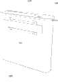
As shown in Figure 1, be the structural representation of shredder.This shredder comprises shredded paper portion 100, shredded paper container 200 and is located at suspension assembly 300 on the lateral wall of shredded paper container 200.Shredded paper portion 100 is provided with waste paper inlet 110, and shredded paper container 200 is connected and holds by shredded paper inlet 110 shredded papers that enter with shredded paper portion 100.
On shredder, increase suspension assembly, can make things convenient for taking at any time and can effectively utilizing the space of shredder.
Embodiment 1
As shown in Figure 2, be the decomposition chart of the suspension assembly 300 of present embodiment.Suspension assembly 300 comprises the slip button 310 and the stripe board 320 that can be attached on the plane.Stripe board 320 is fixed or removably is located on the lateral wall of shredded paper container 300, and stripe board 320 is arranged in the button 310 that slides.
In the present embodiment, slip button 310 comprises slidable panels 311 and fixing feet 312.Slidable panels 311 comprises panel body 311a and the edge 311b that is located at panel body 311a both sides and gives prominence to perpendicular to panel body 311a, fixing feet 312 is located at four jiaos of slidable panels 311 and fixedly connected with outstanding edge 311b, make fixing feet 312 and panel body 311a not at same horizontal plane, and form the activity space that holds stripe board 320 between fixing feet 312 and the plane, panel body 311a place.Fixing feet 312 is used for slip button 310 is connected with outer surface level such as wall, workbench sidewall etc., can adopt multiple connected mode as welding, be spirally connected etc.In the present embodiment, on fixing feet 312, open screw, and attachment screw 313 button 310 that will slide is fixing.
As shown in Figure 2, for making things convenient for stripe board 320 and the relative slip of the button 310 that slides, the long limit of the plate body of stripe board 320 is provided with smooth projection 322, and projection 322 is slided in the button 310 that slides along 311b inboard, edge.
In other embodiment, the button 310 that slides also can have other the form of expression, as the annulus that can hold stripe board 320 or square groove etc., as long as can with stripe board 320 mutual snappings and convenient mobile.With the shredder increase of hanging mode slidably, can conveniently take and pack up, as shredder being hung on the desk sidewall, when needing to use it is skidded off, finishing using is about to it and pushes back.
Further, the direction on long limit, slidable panels 311 upper edges also is provided with two U type stopper slot 311c that are opened on both sides, and the two ends of stripe board 320 are provided with T shape projection 321.T shape projection 321 head dimensions are greater than the width of stopper slot 311c, and neck size is slightly smaller than the width of stopper slot 311c, can slide in stopper slot 311c.The lateral wall of shredded paper container 200 is provided with connecting hole 210.T shape projection 321 embeds connecting hole 210 makes stripe board 320 be connected with the lateral wall of shredded paper container 200, and T shape projection 321 snaps in stopper slot 311c makes stripe board 320 slide in the scope of stopper slot 311c restriction along the button 310 that slides.Connecting hole 210 is the down big little holes of, and T shape projection 321 enters from macropore, and shredded paper container 200 moves down under the gravity effect during suspension, and T shape projection 321 is moved on relatively, and its thinner neck enters the little bore portion of connecting hole 210, can conveniently take off or install.
T shape projection 321 also can replace with screw, and stopper slot 311c also can be the strip slot of closed at both ends.
The connected mode of the lateral wall of stripe board 320 and shredded paper container 200 also is not limited to the mode of present embodiment, can also adopt as modes such as welding, be spirally connected, as long as the stripe board 320 and the lateral wall of shredded paper container 200 are maintained a certain distance, conveniently being arranged in the button 310 that slides and getting final product.
In other embodiment, for ease of sliding, also can make the button 310 that slides be the smooth cambered surface that suits mutually in position contacting, perhaps smooth projection 322 being replaced with the device that pulley etc. is convenient to slide, guide rail also can be set simultaneously in 311b inboard, edge with the cooperation pulley with stripe board 320.
Fig. 3 (a) is the schematic diagram of 300 3 kinds of duties of suspension assembly in the present embodiment to Fig. 3 (c).Illustrate and be in different positions when stripe board 320 is slided in the button 310 that slides.
Embodiment 2
In the foregoing description, the structure of suspension assembly 300 is applicable to wall-hanging.In other occasions, suspension assembly 300 can also be other form, as shredder will being put in the desk limit, but does not want to destroy the sidewall of desk, just can be held on the edge of desk with the structure of clamping.
As shown in Figure 4, be the decomposition chart of the suspension assembly 300 of present embodiment.But this suspension assembly 300 comprises the travelling carriage 330 and the stripe board 340 of clamping.Stripe board 340 is fixed or removably is located on the lateral wall of shredded paper container 200, and stripe board 340 is arranged in the travelling carriage 330.
In the present embodiment, travelling carriage 330 comprise base plate 331 and with base plate 331 in both sides grip block 332 connected vertically.Grip block 332 can be the integral type elastic construction with base plate 331, conveniently is clamped in the desk edge securely.
Further, base plate 331 is provided with the U-shaped stopper slot 332a that is opened on both sides along stripe board 340 glide directions, and the two ends of stripe board 340 are provided with T shape projection 341.T shape projection 341 head dimensions are greater than the width of stopper slot 332a, and neck size is slightly smaller than the width of stopper slot 332a, can slide in stopper slot 332a.
As shown in Figure 4, for making things convenient for the relative slip of stripe board 340 and travelling carriage 330, grip block 332 is provided with guide rail 333, and the long limit of the plate body of stripe board 340 is provided with roller 342, and roller 342 cooperates guide rails 333 that stripe board 340 is slided in travelling carriage 330.
Be auxiliary suspension assembly 300 clamping stably, suspension assembly 300 also comprises trip bolt 350, and grip block 332 is provided with screw hole 334, and trip bolt 350 is by screw hole 334 auxiliary travelling carriage 330 clampings.
For preventing that trip bolt 350 from destroying the surface at edge when clamping, suspension assembly 300 also comprises rubber blanket 360, and rubber blanket 360 pads are located between the object of trip bolt 350 and clamping.
As shown in Figure 5, be held on the schematic diagram at desktop edge for the suspension assembly 300 of present embodiment.Travelling carriage 330 is clamped in the desktop edge, and trip bolt 350 can make clamping more firm by 334 auxiliary travelling carriage 330 clampings of the screw hole on the grip block 332.Stripe board 340 is connected with the lateral wall of shredded paper container 200 simultaneously, and stripe board 340 is slided in travelling carriage 330, and shredded paper container 200 is slided with stripe board 340.
As the schematic diagram of Fig. 6 (a) 300 3 kinds of duties of suspension assembly to Fig. 6 (c) present embodiment, illustrate be in different positions when stripe board 340 is slided in travelling carriage 330.
The above embodiment has only expressed several embodiment of the present utility model, and it describes comparatively concrete and detailed, but can not therefore be interpreted as the restriction to the utility model claim.Should be pointed out that for the person of ordinary skill of the art under the prerequisite that does not break away from the utility model design, can also make some distortion and improvement, these all belong to protection domain of the present utility model.Therefore, the protection domain of the utility model patent should be as the criterion with claims.