[go: up one dir, main page]

CN201323924Y - Shock-absorbing exhaust shoes - Google Patents

Shock-absorbing exhaust shoes Download PDF

Info

Publication number
CN201323924Y
CN201323924Y CNU2008202010826U CN200820201082U CN201323924Y CN 201323924 Y CN201323924 Y CN 201323924Y CN U2008202010826 U CNU2008202010826 U CN U2008202010826U CN 200820201082 U CN200820201082 U CN 200820201082U CN 201323924 Y CN201323924 Y CN 201323924Y
Authority
CN
China
Prior art keywords
sole
spring
shock
absorbing
inner grid
Prior art date
Legal status (The legal status is an assumption and is not a legal conclusion. Google has not performed a legal analysis and makes no representation as to the accuracy of the status listed.)
Expired - Fee Related
Application number
CNU2008202010826U
Other languages
Chinese (zh)
Inventor
方培基
Current Assignee (The listed assignees may be inaccurate. Google has not performed a legal analysis and makes no representation or warranty as to the accuracy of the list.)
Individual
Original Assignee
Individual
Priority date (The priority date is an assumption and is not a legal conclusion. Google has not performed a legal analysis and makes no representation as to the accuracy of the date listed.)
Filing date
Publication date
Application filed by Individual filed Critical Individual
Priority to CNU2008202010826U priority Critical patent/CN201323924Y/en
Application granted granted Critical
Publication of CN201323924Y publication Critical patent/CN201323924Y/en
Anticipated expiration legal-status Critical
Expired - Fee Related legal-status Critical Current

Links

Images

Landscapes

  • Footwear And Its Accessory, Manufacturing Method And Apparatuses (AREA)

Abstract

本实用新型公开了一种减震排气鞋,鞋底内设有弹簧,鞋底上表面设有排气孔,鞋底侧面设有进气孔。本实用新型的有益效果在于:鞋底有密封空间,鞋底侧边设有进气孔,鞋垫设有排气孔,利用鞋底的内置弹簧,受压时排气,不受压时进气,并且弹簧在生产鞋底或鞋垫时已放入模具中与鞋材密不可分地融洽,非常牢固。并且产生强大的减震效果;打开鞋底的连接装置,可以更换弹簧。而且由于鞋底有密封空间,因此不会进水。

Figure 200820201082

The utility model discloses a shock-absorbing and exhaust shoe, wherein a spring is arranged inside the sole, an exhaust hole is arranged on the upper surface of the sole, and an air intake hole is arranged on the side of the sole. The utility model has the beneficial effects that: the sole has a sealed space, the side of the sole has an air intake hole, and the insole has an exhaust hole. The built-in spring of the sole is used to exhaust air when under pressure and to intake air when not under pressure. The spring is put into the mold when the sole or insole is produced, and is inseparably integrated with the shoe material, and is very firm. A strong shock-absorbing effect is produced; the spring can be replaced by opening the connection device of the sole. Moreover, since the sole has a sealed space, water will not enter.

Figure 200820201082

Description

The damping air exhausting shoes
Technical field
The utility model relates to a kind of footwear, is specifically related to a kind of footwear with damping degassing function.
Background technology
Present damping footwear generally all are that its shortcoming is that cushioning ability is limited with modes such as the ends in the air cushion, pu elastic force post, eva, pu, the screen resilience deficiency, elastic force transfer the too soft fastness that just lost, will make the elastic force deficiency too firmly.And elastic force apparatus is non-exchange.Having the footwear of degassing function, be easy to entry, all is passive exhaust ventilation.
The utility model content
The purpose of this utility model is to overcome the deficiencies in the prior art, and a kind of damping air exhausting shoes is provided, and screen resilience is enough and firmly, elastic force apparatus can be changed, and also has good degassing function, is difficult for water inlet.
The technical solution adopted in the utility model is as follows:
The damping air exhausting shoes is provided with spring in the sole, sole upper surface is provided with steam vent, and the sole side is provided with air admission hole.
As the improvement to such scheme, sole is provided with interior lattice, and interior lattice are shaped as circular or square, and Nei Genei is fixed with the spring that adapts with its size; Between interior lattice and the interior lattice, be connected between Nei Ge and air admission hole, steam vent.
As improvement to such scheme, be provided with the elastic force post in the sole, spring housing is outside the elastic force post.
As improvement to such scheme, be provided with the elastic force post in the sole, spring merges in material for sole of shoe.Its elastic force post and footwear sole construction are when producing sole spring to be put into die for shoe-sole, and filler for fluid footwear material forms footwear material sole, shoe-pad, the elastic force rod structure inseparable with spring again.Material for sole of shoe can be PU, EVA, TPU, TPR, PVC, RB or other liquid footwear material.
As the improvement to such scheme, sole is made up of upper base and going to the bottom, and the upper base upper surface is provided with steam vent, upper base and go to the bottom between leave the room, empty place is equipped with the spring that adapts with its size; Upper base with go to the bottom between by slide fastener, shoestring, VELCRO, button, shoe buckle, magnet buckle, four-part button or rubber root band be connected.
As the improvement to such scheme, rear end, sole bottom is provided with heel, and spring housing is embedded in the heel outside heel or with the fusion of heel material.
The beneficial effects of the utility model are, sole has seal cavity, the sole side is provided with air admission hole, shoe-pad is provided with steam vent, utilizes the built-in spring of sole, exhaust during pressurized, not air inlet during pressurized, and spring has been put into mould and has been merged with material for sole of shoe inseparablely when producing sole, very firm, and produces powerful damping effect; Open the jockey of sole, can change spring.And, therefore can not intake because sole has seal cavity.
Description of drawings
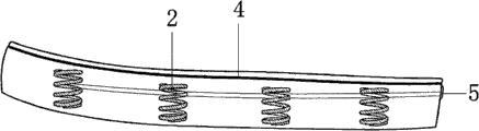
Fig. 1, Fig. 2, Fig. 3 are the schematic diagram of sole side, upper surface and the lower surface of the utility model embodiment one.
Fig. 4, Fig. 5, be sole side schematic view and the reference diagram of spring under the sole different conditions of the utility model embodiment two.
Fig. 6, Fig. 7 are the sole construction profile of the utility model embodiment three.
Fig. 8, Fig. 9 are the footwear sole construction schematic diagram of the utility model embodiment four.
The specific embodiment
The operation principle of damping air exhausting shoes is the seal cavity at sole, utilizes the elastic force of built-in spring, the pressurized exhaust when landing by walking, and decompression air inlet during starting produces damping effect.
In order to reach above-mentioned effect, we must cooperatively interact in the selection of the design of sole and spring.In the selection of spring, to reach 2-4cm with diameter in the main so stressed place of heel, tensile strength is enough to support the spring of the general weight of human body, diameter, the less spring of elastic force can be used in sole the place ahead.
The design of main emphasis of the present utility model and sole specifically has several designs:
Embodiment one: sole is made of whole rubber-sole, is provided with lattice in several in sole, fixed in position spring 2 in the interior lattice 1, and interior lattice size adapts with the spring size.Shoe-pad above the sole is provided with steam vent 3, and guy hook 4 has been made in the sole top.Be provided with a unidirectional air inlet 5 in the downward a little position of the backguy ditch at sole rear.The sole side is provided with steam vent, and these steam vents all communicate with the space of air admission hole, interior lattice.The exhaust when footwear of making like this will pressurized, not air inlet during pressurized, and produce powerful damping effect.Sole also can be made transparent color, has better ornamental.Because in the sole is confined space, also can not intake.
Embodiment two: spring 2 is put into the mould of sole, be fed into the liquid material for sole of shoe again, for example PU, EVA, TPU, TPR, PVC, RB or other liquid footwear material.Just can produce sole, shoe-pad or the elastic force post of band spring.Be provided with some hollow elastic force posts 6 in the sole, spring can be enclosed within outside the elastic force post, in the time of also can producing sole at the beginning spring is put into mould, is fed into liquid footwear material again, forms spring and sole as the cement fusion structure inseparable with reinforcing bar.As long as elastic force post or sole, shoe-pad adopt softer material, sole just can remain with the elasticity of spring, and be connected firmly, lifting surface area is big.The center of spring is all made hollow, forms the confined space of sole, cooperate again with embodiment one in the intake and exhaust structure of identical sole, exhaust in the time of just can realizing pressurized, not air inlet during pressurized.
Embodiment three: sole by upper base 7, go to the bottom 8 and egative film form, upper base and go to the bottom between leave the room of spring size, place some springs.Upper base has steam vent, on put into spring in the middle of going to the bottom, lump together again.Wrap the middle skin material bar 9 that has a slide fastener of one deck more in the above.The Position Control of slide fastener is fitted in the upper base inboard in the top of middle leather strap, fits with vamp.The leather strap below is ploughed under the inboard and the egative film of going to the bottom and is fitted.The footwear of this structure, sole have the slide fastener jockey, as long as the jockey at the end is opened, just can separate upper base with going to the bottom.The spring of the inside is taken out replacing, to adapt to different motion needs.Such sole design can be joined multiple sole by a footwear, as at the bottom of flat, the snowfield, climb the mountain at the end etc., change in different occasions.Also can join a plurality of vamps by a kind of sole,, meet the different needs as different styles such as high tube, low tubes.The leather strap that connects between slide fastener preferably will be made by resilient material, prevents that pressurized is wrinkling.On jockey between going to the bottom except that slide fastener, can also use that shoestring, VELCRO, button, shoe buckle, magnet are buckled, four-part button or rubber root band connect, as long as reach detachable effect.
Embodiment four: on the heel of spring application and high-heeled shoes, heel can be put into spring and pour into material again directly by pu or tpu or the production of eva material for sole of shoe in heel mould during production, and such heel was both flexible, and was firmly enough again.Heel is preferably made transparent, and ornamental is stronger like this.For the another kind design of heel, can be at heel 10 outer casing springs 2.The footwear holder 11 of one radius greater than the spring radius arranged at the heel bottom, and spring is withstood.Earlier spring is inserted in heel during production, heel and footwear holder are fitted then.Above-mentioned these two kinds of structures, if heel hollow, and be provided with air inlet, steam vent, also can realize air intake-exhaust.High-heeled shoes with this spline structure are worn comfortablely especially, can not feel well because of heel is high.

Claims (9)

1、减震排气鞋,其特征在于:鞋底内设有弹簧,鞋底上表面设有排气孔,鞋底侧面设有进气孔。1. Shock-absorbing exhaust shoes, characterized in that: springs are arranged in the sole, exhaust holes are arranged on the upper surface of the sole, and air inlet holes are arranged on the side of the sole. 2、如权利要求1所述的减震排气鞋,其特征在于:鞋底上设有内格,内格形状为圆形或方形,内格内固定设有与其大小相适应的弹簧或鞋底材料与弹簧融合的弹力柱;内格与内格之间,内格与进气孔、排气孔间相连通。2. The shock-absorbing and exhausting shoes as claimed in claim 1, characterized in that: there is an inner grid on the sole, the shape of the inner grid is round or square, and the inner grid is fixed with a spring or sole material suitable for its size. The elastic column integrated with the spring; the inner grid is connected with the inner grid, and the inner grid is connected with the air intake hole and the exhaust hole. 3、如权利要求1所述的减震排气鞋,其特征在于:鞋底上设有内格,内格形状为圆形或方形,内格内固定设有与其大小相适应的鞋底材料与弹簧融合而成的弹力柱;内格与内格之间,内格与进气孔、排气孔间相连通。3. The shock-absorbing and exhausting shoes according to claim 1, characterized in that: there is an inner grid on the sole, the shape of the inner grid is round or square, and the inner grid is fixed with a sole material and a spring suitable for its size. The elastic column formed by fusion; the inner grid is connected with the inner grid, and the inner grid is connected with the air intake hole and the exhaust hole. 4、如权利要求1所述的减震排气鞋,其特征在于:鞋底内设有弹力柱,弹簧套在弹力柱外,或与鞋底材料融合在弹力柱内。4. The shock-absorbing and exhausting shoes according to claim 1, characterized in that: elastic columns are arranged inside the soles, and the springs are sheathed outside the elastic columns, or are fused with the sole material in the elastic columns. 5、如权利要求1所述的减震排气鞋,其特征在于:鞋底内设有弹力柱,弹簧与鞋底材料融合在弹力柱内。5. The shock-absorbing exhaust shoe according to claim 1, characterized in that: there is an elastic column inside the sole, and the spring and the material of the sole are fused in the elastic column. 6、如权利要求1所述的减震排气鞋,其特征在于:鞋底或鞋垫内设有弹力柱,弹簧融合在弹力柱内,其弹力柱与鞋底或鞋垫结构是生产鞋底或鞋垫时把弹簧放入鞋底或鞋垫模具中,再灌注流质鞋材,形成鞋材与弹簧密不可分的鞋底、鞋垫、弹力柱结构。6. The shock-absorbing and exhausting shoes according to claim 1, characterized in that: the sole or the insole is provided with an elastic column, and the spring is fused in the elastic column, and the structure of the elastic column and the sole or the insole is the same as when the sole or the insole is produced. The spring is put into the sole or insole mold, and then the fluid shoe material is perfused to form a shoe sole, insole, and elastic column structure in which the shoe material and the spring are inseparable. 7、如权利要求1所述的减震排气鞋,其特征在于:鞋底由上底和下底组成,上底上表面设有排气孔,上底与下底间留有空位,空位处容置有与其大小相适应的弹簧;上底与下底之间通过拉链、鞋带、魔术贴、纽扣、鞋扣、磁铁扣、四合扣或橡根带连接。7. The shock-absorbing and exhausting shoes according to claim 1, characterized in that: the sole is composed of an upper bottom and a lower bottom, the upper surface of the upper bottom is provided with vent holes, and there is a space between the upper bottom and the lower bottom, and the space in the space is A spring suitable for its size is accommodated; the upper bottom and the lower bottom are connected by zippers, shoelaces, Velcro, buttons, shoe buckles, magnet buckles, snap buttons or elastic bands. 8、如权利要求1所述的减震排气鞋,其特征在于:鞋底底部后端设有鞋跟,弹簧套在鞋跟外。8. The shock-absorbing exhaust shoe according to claim 1, characterized in that: a heel is provided at the rear end of the bottom of the sole, and the spring is covered outside the heel. 9、如权利要求1所述的减震排气鞋,其特征在于:鞋底底部后端设有鞋跟,弹簧与鞋底材料融合嵌在鞋跟内。9. The shock-absorbing and venting shoe according to claim 1, characterized in that: a heel is provided at the rear end of the bottom of the sole, and the spring is fused with the material of the sole and embedded in the heel.
CNU2008202010826U 2008-09-26 2008-09-26 Shock-absorbing exhaust shoes Expired - Fee Related CN201323924Y (en)

Priority Applications (1)

Application Number Priority Date Filing Date Title
CNU2008202010826U CN201323924Y (en) 2008-09-26 2008-09-26 Shock-absorbing exhaust shoes

Applications Claiming Priority (1)

Application Number Priority Date Filing Date Title
CNU2008202010826U CN201323924Y (en) 2008-09-26 2008-09-26 Shock-absorbing exhaust shoes

Publications (1)

Publication Number Publication Date
CN201323924Y true CN201323924Y (en) 2009-10-14

Family

ID=41175904

Family Applications (1)

Application Number Title Priority Date Filing Date
CNU2008202010826U Expired - Fee Related CN201323924Y (en) 2008-09-26 2008-09-26 Shock-absorbing exhaust shoes

Country Status (1)

Country Link
CN (1) CN201323924Y (en)

Cited By (2)

* Cited by examiner, † Cited by third party
Publication number Priority date Publication date Assignee Title
CN104257005A (en) * 2014-09-30 2015-01-07 瞿德成 Damping spring sole or insole machining method
CN104510078A (en) * 2014-12-19 2015-04-15 方柏明 Soles shock absorber and manufacturing die and method, shock absorbing soles and manufacturing method thereof

Similar Documents

Publication Publication Date Title
US6009637A (en) Helium footwear sole
CN103734985A (en) Air cushion type inner circulation shoe sole
CN105411090A (en) Integrally-formed shoe sole article with dual density and manufacturing method thereof
CN201323924Y (en) Shock-absorbing exhaust shoes
CN102665465A (en) Shoes and method of making the same
CN206603320U (en) Adjustable foot pressure shoe structure
CN201831033U (en) Breathable shoes
CN210276085U (en) Shock-absorbing comfortable shoes
CN203952604U (en) At the bottom of the interior circulation shoe of air-cushion type
CN2919937Y (en) Breathable shoe structure for shock resistance and pressure relief
CN201911393U (en) Casual health-caring sneaker
CN201204985Y (en) Inflatable elastic shock-absorbing sole
CN203575745U (en) Air cushion
CN201491799U (en) Novel sports shoe air cushion
CN209610004U (en) A kind of health care sneaker
CN219813324U (en) A kind of elastic casual shoes
CN201571572U (en) Massage sole
CN209694204U (en) self-inflating sole
CN221769438U (en) A cowhide women's short boots with good air permeability
CN204157780U (en) Laborsaving rubber boots
CN205143642U (en) Leather shoes for men
CN106723638B (en) Shock absorption breathable shoes
CN216293185U (en) Sole with shock-absorbing function
CN203244005U (en) Air circulation healthcare shoe
CN205058462U (en) A mould for making dual density integrated into one piece's sole article

Legal Events

Date Code Title Description
C14 Grant of patent or utility model
GR01 Patent grant
CF01 Termination of patent right due to non-payment of annual fee

Granted publication date: 20091014

Termination date: 20150926

EXPY Termination of patent right or utility model