CN201323594Y - Network device for switching between two network groups - Google Patents
Network device for switching between two network groups Download PDFInfo
- Publication number
- CN201323594Y CN201323594Y CNU200820072768XU CN200820072768U CN201323594Y CN 201323594 Y CN201323594 Y CN 201323594Y CN U200820072768X U CNU200820072768X U CN U200820072768XU CN 200820072768 U CN200820072768 U CN 200820072768U CN 201323594 Y CN201323594 Y CN 201323594Y
- Authority
- CN
- China
- Prior art keywords
- network
- chip
- switching
- switch
- microprocessor
- Prior art date
- Legal status (The legal status is an assumption and is not a legal conclusion. Google has not performed a legal analysis and makes no representation as to the accuracy of the status listed.)
- Expired - Lifetime
Links
Images
Landscapes
- Data Exchanges In Wide-Area Networks (AREA)
Abstract
The utility model discloses a network device for switching between two network groups, which aims to establish a network channel between a computer terminal and an internal network or external network, in which the computer terminal is connected with a network switching chip through a network isolation transformer, and the switching behavior of the network switching chip is controlled by a control signal of a control unit. The control unit inputs the control signal into a microprocessor through a switching button and a toggle switch so as to induce the latch chip of the microprocessor to send out a control signal for the network switching chip to change working state. By applying a physical layer chip and the switching chip instead of a relay, and incorporating the single board computer control technology, the utility model is presented with a digital circuit design scheme which mainly depends upon an integrated circuit chip, thereby avoiding frequent jumper connection between network cables during teaching experiment, and ensuring efficiency and accuracy of experiment.
Description
Technical field
The utility model provides a kind of network equipment of realizing that two kinds of network packet are switched, is implemented in to divide into groups between two kinds of network configurations or network equipment that group switches, belongs to the computer network communication technology field.
Background technology
Conventional method is carried out jumper connection with the network cable at inside and outside LA Management Room, take plug netting twine and network equipment auto-negotiation time, frequent jumper connection netting twine easily produces instant high-voltage, easily puncture the network equipment, network equipment network interface unit produces wearing and tearing, and situation all can influence network equipment useful life and service behaviour.
Each network device manufacturers is at the network topology handoff technique at present, mainly to two kinds of switch modes: (1). based on single desktop computer is applying unit, need take a peripheral parts interconnected slot (PCI) on the computer motherboard, a network switch card is installed, corresponding integrated driving and function software are installed under computer Windows operating system platform, and every operation realizes that once inside and outside 2 kinds of networks switch.Application operating is loaded down with trivial details, and driving and function software are subject to the conventional version of Windows.Not manageability is used in teaching, and maintenance workload is big, can't accurately guarantee to test quality.
Portable computer can't be implemented the network switching by adopting said method owing to be subjected to volume and machine intimate limited space; (2). based on the relay technology, realize network centralized management and control be need not peripheral software and drives and control operation, realize that substantially centralization, automated network switch.It is knife switch work switch mode that the deficiency that has product mainly embodies a concentrated expression of relay framework principle, and equipment switches noise and power consumption, owing to use electronic devices and components to be mechanical realization, product whole service life and product life cycle are shorter relatively;
According to above-mentioned two types of products, in realizing application, there are many deficiencies, especially should consider in Web-based instruction experimentation to provide multiple teaching platform system coexistence mechanism, realizes demands such as simple to operate, environmental protection, low-power consumption, utility model network packet switching device shifter.According to development requirement, guaranteeing under the normal communication state, support 4 groups independently between two kinds of network configurations, to carry out group mode switching or group mode switching, every group supports that 6 computers (are that each switch unit is supported 2 computers, number per 3 switch units in a left side are 1 group), totally 4 groups (24 computers), moment dynamically switches between 2 kinds of networks, quick characteristics of response time.
The utility model content
The utility model discloses a kind of network equipment of realizing that two kinds of network packet are switched, be implemented in and carry out group mode or group's switching between two kinds of network configurations, when having solved the switching of conventional method network packet, frequent jumper connection netting twine easily punctures the network equipment, it is bigger to wear and tear, and influences network equipment useful life and service behaviour problem.
Two kinds of network packet switching device shifters of realization of the present utility model, it is characterized in that: form by N switch unit and 1 control unit, in each switch unit, terminal switches chip by network isolation transformer and network and is connected, and network switching chip connects and composes network channel by network isolation transformer and internal network or external network respectively;
Control unit by microprocessor, switching key, toggle switch, latch chip and topological indicator light constitutes, switching key, toggle switch connect the signal input part of microprocessor, the microprocessor signals output transmits control signal to the trigger end that latchs chip, latching the chip signal output is connected with the network switching chip controls end and the control unit topology indicator light interface of switch unit respectively, export its synchronous control signal, control each cell operation state.
Described packet switching device, its network interface is characterised in that: switch unit physical chip input switches chip with network and adopts control bus to be connected, the output of physical chip is connected with the network interface lamp of internal network, external network and terminal respectively, receive network and switch the chip data message signals, carry out the signal winding and handle, be sent to each network interface lamp respectively.
Described packet switching device, its grouping handoff features is: device realizes that 4 groups switch at two kinds of network channels independently of one another, and every group supports 6 computers, totally 24 computers.Control unit group switching key is to the microprocessor input control signal, and triggering is latched chip and sent control signal to switch unit network switching chip.Network switches chip and connects and composes network channel by network isolation transformer and internal network or external network respectively.
Described packet switching device, its group mode or group mode are characterised in that: the control unit toggle switch is to microprocessor input service mode state signal.
The group mode state: the switching key triggering of control unit group is latched chip and is sent control signal to switch unit network switching chip, and network switches chip and passes through respectively with internal network or external network isolating transformer formation network channel, and realization divides into groups to switch;
The group mode state: any switching key triggering of control unit is latched chip and is sent control signal to switch unit network switching chip, network switches chip respectively by constituting network channel with internal network or external network isolating transformer, realizes that each switch unit switches synchronously.
The concrete course of work
(1). network connects operating state:
Network switches the response of the high and low level signal in the controlled unit of chip 3 control interfaces, and each group's switch unit is in internal network or external network communication state.
Terminal adopts the netting twine medium to be connected with network interface 1, network isolation transformer 2 receives network signal, carry out the noise Filtering Processing and be sent to network switching chip 3, network switches chip reception network signal to be handled, be forwarded to the network isolation transformer of internal network 4 or external network 14, synchronously network signal be sent to physical chip 6.
Network isolation transformer 4 14 connect network signal, export internal network 5 to or external network connects 13 communication equipment by network interface;
The physical chip input receives network and switches the network signal that chip sends, and network signal is carried out winding handle, and the output indicator control signal is sent to the network interface flow lamp of internal network 7 or external network 15 and terminal 8 respectively.
Internal network or external network interface send network signal to the terminal interface, and be in like manner described.
(2). grouping switch operating state:
Control unit group switching key 9 is to the P1 of microprocessor 10 group pin input control signal, microprocessor P0 or P2 group pin are organized the pin sending controling instruction to the D that latchs chip 11 respectively, and triggering is latched chip Q group pin and sent the topological indicator light 12 that corresponding switch unit network switching chip and corresponding switch unit are given in instruction respectively.
The switch unit network switches the response that the chip controls interface is subjected to high and low level signal, and handover network is in internal network or external network communication state.It is described with above-mentioned (1) network connection operating state that network signal is transmitted processing.
Each group's topology indicator light of control unit is latched the response of the high and low level signal of chip Q group pin, and on behalf of group's switch unit, indicator light be in internal network with redness, or represents group's switch unit to be in external network with green.
(3). device group switch operating state:
Device is realized the function that group mode or group mode dynamically switch.Toggle switch 16 set group modes, to the microprocessor input control signal, the operation of microprocessor wait switching key, switch unit group switching key operation signal are handled with above-mentioned (2) grouping switch operating state, and it is described that network signal forwarding processing connects operating state with above-mentioned (1) network.
Toggle switch set group mode, to the microprocessor input control signal, microprocessor is waited for any switching key operation, the control unit switching key is to the microprocessor input control signal, microprocessor receives switch-over control signal, handle the internal network or the external network communication state of each switch unit group, with switch-over control signal topological structure unanimity, microprocessor P0 and P2 group pin send with a kind of control command to respectively latching chip D group pin respectively, respectively latch chip Q group pin and send instruction respectively, promptly realize group's switch operating state to each switch unit network switching chip.It is described with above-mentioned (1) network connection operating state that network signal is transmitted processing.
The utility model is compared with the existing network switching device shifter and had the following advantages: the utility model does not adopt the relay technology, Applied Physics layer chip, switching chip, in conjunction with the single board computer control technology, formation is based on the digitizer design of integrated circuit (IC) chip, frequent jumper connection netting twine in education experiment has guaranteed conventional efficient and accuracy rate.Each experiment group independently switches or has the synchronous group of a unitary device handoff functionality, satisfy information security function needs, intelligent network is isolated, and reduce network equipment wearing and tearing, be laboratory structure multiple network teaching platform, convenient with the many demand of study group situation establishment teaching experiment environment to network topology structure automation, grouping switching, group synchronization handoff functionality.
The network packet switching device shifter is guaranteeing under the normal communication state, support 4 groups of independent between two kinds of network configurations, divide into groups switching or group's switchings, every group supports that 6 computers (are that each switch unit is supported 2 computers, number per 3 switch units in a left side are 1 group), totally 4 groups (24 computers), moment dynamically switches between 2 kinds of networks, quick characteristics of response time.
Description of drawings
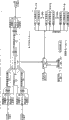
Fig. 1 is the utility model theory diagram.
Embodiment
According to shown in Figure 1, form by 12 switch units and 1 control unit, in each switch unit, terminal switches chip 3 (model MAX4892ETX) by network isolation transformer 2 (model 13F-2003NL) and network and is connected, and network switches chip 3 and connects and composes network channel by network isolation transformer 4,14 (model 13F-2003NL) and internal network or external network respectively;
The input of physical chip 6 (model RTL8208BF) switches chip 3 with network and adopts control bus to be connected, the output of physical chip 6 is connected with internal network, external network and terminal mouth lamp respectively, receive network and switch chip 3 data message triggering signals, carry out the signal winding and handle, be sent to each network port lamp respectively.
Control unit by microprocessor (model AT89LS52), switching key, toggle switch, latch chip (model 74HC574N) and topological indicator light 12 and constitute, switching key 9, toggle switch 16 connect the signal input part of microprocessor, input control signal, the signal output part of microprocessor connects the trigger end that latchs chip, the signal output part that latchs chip switches the chip signal control end with the network of switch unit and is connected, and controls its operating state.
Toggle switch connects the microprocessor control interface by control bus, and microprocessor receives the toggle switch closure signal, sends command adapted thereto to latching chip, realizes Packet State mode of operation or group's state mode of operation.
Group mode: every group supports that 6 computers (are that each switch unit is supported 2 computers, number per 3 switch units in a left side are 1 group), totally 4 groups (24 computers) operate by the other switching key of corresponding group respectively, and moment dynamically switches between 2 kinds of networks;
Group mode: carry out inside and outside switching synchronously by any switch key operation implement device;
By to the toggle switch position operation, which kind of control model the real-time Dynamic Recognition device of microprocessor is in, and is convenient to the switching key operation is realized inside and outside switching;
Claims (4)
1, two kinds of network packet switching device shifters of a kind of realization, it is characterized in that: form by N switch unit and 1 control unit, in each switch unit, terminal switches chip by network isolation transformer and network and is connected, and network switching chip connects and composes network channel by network isolation transformer and internal network or external network respectively;
Control unit by microprocessor, switching key, toggle switch, latch chip and topological indicator light constitutes, switching key, toggle switch connect the signal input part of microprocessor, the microprocessor signals output transmits control signal to the trigger end that latchs chip, latching the chip signal output is connected with the network switching chip controls end and the control unit topology indicator light interface of switch unit respectively, export its synchronous control signal, control each cell operation state.
2, two kinds of network packet switching device shifters according to claim 1, it is characterized in that: switch unit physical chip input switches chip with network and adopts control bus to be connected, the output of physical chip is connected with the network interface lamp of internal network, external network and terminal respectively, receive network and switch the chip data message signals, carry out the signal winding and handle, be sent to each network interface lamp respectively.
3, two kinds of network packet switching device shifters according to claim 1 is characterized in that: device realizes that 4 groups switch at two kinds of network channels independently of one another, and every group supports 6 computers, totally 24 computers; Control unit group switching key is to the microprocessor input control signal, and triggering is latched chip and sent control signal to switch unit network switching chip; Network switches chip and connects and composes network channel by network isolation transformer and internal network or external network respectively.
4, two kinds of network packet switching device shifters according to claim 1 is characterized in that: the control unit toggle switch is to microprocessor input service mode state signal;
The group mode state: the switching key triggering of control unit group is latched chip and is sent control signal to switch unit network switching chip, and network switches chip and passes through respectively with internal network or external network isolating transformer formation network channel, and realization divides into groups to switch;
The group mode state: any switching key triggering of control unit is latched chip and is sent control signal to switch unit network switching chip, network switches chip respectively by constituting network channel with internal network or external network isolating transformer, realizes that each switch unit switches synchronously.
Priority Applications (1)
| Application Number | Priority Date | Filing Date | Title |
|---|---|---|---|
| CNU200820072768XU CN201323594Y (en) | 2008-11-19 | 2008-11-19 | Network device for switching between two network groups |
Applications Claiming Priority (1)
| Application Number | Priority Date | Filing Date | Title |
|---|---|---|---|
| CNU200820072768XU CN201323594Y (en) | 2008-11-19 | 2008-11-19 | Network device for switching between two network groups |
Publications (1)
| Publication Number | Publication Date |
|---|---|
| CN201323594Y true CN201323594Y (en) | 2009-10-07 |
Family
ID=41160965
Family Applications (1)
| Application Number | Title | Priority Date | Filing Date |
|---|---|---|---|
| CNU200820072768XU Expired - Lifetime CN201323594Y (en) | 2008-11-19 | 2008-11-19 | Network device for switching between two network groups |
Country Status (1)
| Country | Link |
|---|---|
| CN (1) | CN201323594Y (en) |
Cited By (2)
| Publication number | Priority date | Publication date | Assignee | Title |
|---|---|---|---|---|
| CN101420373B (en) * | 2008-11-19 | 2011-11-09 | 吉林中软吉大信息技术有限公司 | Method for switching between two types of network packets and network apparatus therefor |
| CN114415811A (en) * | 2022-03-28 | 2022-04-29 | 成都前锋信息技术股份有限公司 | A high-compatibility computer motherboard |
-
2008
- 2008-11-19 CN CNU200820072768XU patent/CN201323594Y/en not_active Expired - Lifetime
Cited By (3)
| Publication number | Priority date | Publication date | Assignee | Title |
|---|---|---|---|---|
| CN101420373B (en) * | 2008-11-19 | 2011-11-09 | 吉林中软吉大信息技术有限公司 | Method for switching between two types of network packets and network apparatus therefor |
| CN114415811A (en) * | 2022-03-28 | 2022-04-29 | 成都前锋信息技术股份有限公司 | A high-compatibility computer motherboard |
| CN114415811B (en) * | 2022-03-28 | 2022-05-31 | 成都前锋信息技术股份有限公司 | A high-compatibility computer motherboard |
Similar Documents
| Publication | Publication Date | Title |
|---|---|---|
| CN101867221B (en) | Single board and method for power monitoring in board | |
| CN101141263A (en) | Method, control cell and system for controlling ethernet power supply | |
| CN108255754B (en) | A kind of I3C main equipment of compatible I2C, I3C master-slave equipment communication system and method | |
| CN202486575U (en) | Numerical control machine tool control interface device using EtherCAT bus | |
| CN102012877B (en) | Flushbonading stored program control exchange for expanding embedded processor GPIO by using CPLD | |
| CN102141833A (en) | USB power management system and method thereof | |
| CN101420373B (en) | Method for switching between two types of network packets and network apparatus therefor | |
| CN201323594Y (en) | Network device for switching between two network groups | |
| CN113433838A (en) | Communication processing method of digital simulation system and intelligent simulation interface device | |
| CN109407574B (en) | Multi-bus selectable output control device and method thereof | |
| CN201876698U (en) | Multi-path isolated programmable controller | |
| CN206422791U (en) | A kind of pattern fast switch over type network switch | |
| CN203277915U (en) | Multifunctional communication conjunction box | |
| CN202334547U (en) | Dual-network access physical isolation online switch device based on USB bus | |
| CN201821378U (en) | Novel router | |
| CN202935897U (en) | Sudden-stop lock switch position recognition device of belt conveyor | |
| CN203277916U (en) | A junction box | |
| CN207516414U (en) | A kind of high pressure program controlled matrix switch | |
| CN208752611U (en) | A kind of protocol controller of serial protocol | |
| CN208386539U (en) | A kind of co-located filter of multichannel cavity | |
| CN201663653U (en) | Hybrid module type high-definition matrix system | |
| CN2921985Y (en) | Old elevator reforming switching device | |
| CN212992045U (en) | Isolated operation power distribution room system | |
| CN110798390A (en) | A communication system and communication method for power supply and distribution system of submarine observation network | |
| CN114567671B (en) | ARM server and data transmission method |
Legal Events
| Date | Code | Title | Description |
|---|---|---|---|
| C14 | Grant of patent or utility model | ||
| GR01 | Patent grant | ||
| AV01 | Patent right actively abandoned |
Granted publication date: 20091007 Effective date of abandoning: 20081119 |