CN201318354Y - Inclined plane buckle - Google Patents
Inclined plane buckle Download PDFInfo
- Publication number
- CN201318354Y CN201318354Y CNU2008203028780U CN200820302878U CN201318354Y CN 201318354 Y CN201318354 Y CN 201318354Y CN U2008203028780 U CNU2008203028780 U CN U2008203028780U CN 200820302878 U CN200820302878 U CN 200820302878U CN 201318354 Y CN201318354 Y CN 201318354Y
- Authority
- CN
- China
- Prior art keywords
- buckle
- hook
- hole
- elastic arm
- snap
- Prior art date
- Legal status (The legal status is an assumption and is not a legal conclusion. Google has not performed a legal analysis and makes no representation as to the accuracy of the status listed.)
- Expired - Fee Related
Links
Images


Landscapes
- Buckles (AREA)
Abstract
本实用新型提供一种斜面卡扣,包括一卡入部和一扣止部。卡入部包括一弹性臂和一位于弹性臂一端的卡钩。扣止部包括一用于容纳卡入部的通孔和一用于和卡钩配合、防止卡入部退出通孔的止动件。卡钩和止动件分别包括一用于彼此接触的斜面。卡钩的斜面和弹性臂之间的夹角大于90°。由于斜面的导引作用,在卡入部和扣止部被分开时,卡扣不会受到损坏。
The utility model provides a buckle on an inclined plane, which comprises a snap-in part and a buckle-stop part. The engaging part includes an elastic arm and a hook at one end of the elastic arm. The locking part includes a through hole for accommodating the engaging part and a stopper for cooperating with the hook and preventing the engaging part from withdrawing from the through hole. The hook and the stopper respectively include a slope for contacting each other. The angle between the slope of the hook and the elastic arm is greater than 90°. Due to the guiding effect of the inclined surface, when the snap-in part and the buckle part are separated, the buckle will not be damaged.
Description
技术领域 technical field
本实用新型涉及一种固定件,特别涉及一种卡扣。The utility model relates to a fixing part, in particular to a buckle.
背景技术 Background technique
卡扣是常用的固定件,其一般包括分别位于两物件上的一卡入部及一扣止部,使用时,将卡入部插入扣止部中使二者配合,即可将该两物件固定在一起。Buckles are commonly used fixing parts, which generally include a snap-in part and a buckle part respectively located on the two objects. Together.
传统的卡扣当卡入部插入扣止部后,需要很大的力才能使它们分开,而且在分开过程中还容易破坏卡入部或扣止部。因此,有必要对传统的卡扣做出改进。In traditional buckles, when the snap-in part is inserted into the buckle part, a large force is required to separate them, and the snap-in part or the buckle part is easily damaged during the separation process. Therefore, it is necessary to improve the traditional buckle.
实用新型内容 Utility model content
本实用新型提供一种斜面卡扣,其在被分开时不会受到损坏。The utility model provides an inclined surface buckle, which will not be damaged when it is separated.
所述斜面卡扣,包括一卡入部和一扣止部。卡入部包括一弹性臂和一位于弹性臂一端的卡钩。扣止部包括一用于容纳卡入部的通孔和一用于和卡钩配合、防止卡入部退出通孔的止动件。卡钩和止动件分别包括一用于彼此接触的斜面。卡钩的斜面和弹性臂之间的夹角大于90°。The inclined buckle includes a locking part and a locking part. The engaging part includes an elastic arm and a hook at one end of the elastic arm. The locking part includes a through hole for accommodating the engaging part and a stopper for cooperating with the hook and preventing the engaging part from withdrawing from the through hole. The hook and the stopper respectively include a slope for contacting each other. The angle between the slope of the hook and the elastic arm is greater than 90°.
由于斜面的导引作用,在卡入部和扣止部被分开时,卡扣不会受到损坏。Due to the guiding effect of the inclined surface, when the snap-in part and the buckle part are separated, the buckle will not be damaged.
附图说明 Description of drawings
图1是一电子装置的前视示意图,其包括本实用新型一优选实施方式的卡扣。FIG. 1 is a schematic front view of an electronic device, which includes a buckle according to a preferred embodiment of the present invention.
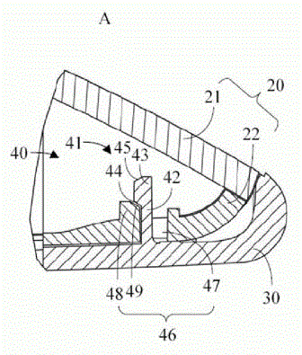
图2是图1中A部分的放大图。Fig. 2 is an enlarged view of part A in Fig. 1 .
具体实施方式 Detailed ways
请参考图1,其揭示了一电子装置10。该电子装置10包括一壳体20及一可更换地安装于壳体20上的前面板30。通过更换前面板30,可以方便的改变电子装置10的外形,从而满足消费者个性化的需求。壳体20和前面板30通过多个斜面卡扣40连接。Please refer to FIG. 1 , which discloses an
请参考图2,壳体20由前盖22和后盖21组成,前面板30安装于前盖22上。Please refer to FIG. 2 , the
在前面板30上形成有斜面卡扣40的卡入部41,卡入部41包括一从前面板30延伸的弹性臂42和位于弹性臂42远离前面板30一端的卡钩43,卡钩43包括一靠近弹性臂42的斜面44和一远离弹性臂42的第二斜面45,且斜面44和弹性臂42之间的夹角大于90°。On the
在前盖22上形成有斜面卡扣40的扣止部46,扣止部46包括一用于容纳卡入部41的通孔47和一用于和卡钩43配合、防止卡入部41退出通孔47的止动件48,止动件48上形成有用于和卡钩43上斜面44接触的斜面49。在本实施方式中,止动件48形成于通孔47外,在其他实施方式中,止动件48也可形成于通孔47内的壁上。On the
当需要将前面板30安装到壳体20上时,首先,将前面板30和壳体20彼此接触,每个卡入部41和扣止部46彼此对应,卡钩43的第二斜面45和通孔47的壁接触。然后,用力驱使前面板30和壳体20彼此贴紧,卡钩43向通孔47内运动,通孔47的壁顶触卡钩43,使得和卡钩43相连的弹性臂42变形,卡钩43因此可通过通孔47。当卡钩43通过通孔47后,弹性臂42恢复原状,卡钩43的斜面44和扣止部46的斜面49配合,限制卡钩43从通孔47中退出。从而,壳体20和前面板30即被连接在一起。When it is necessary to install the
当需要从壳体20上拆下前面板30时,用力驱使前面板30和壳体20分开。由于斜面44、49的导引,卡钩43会在拆卸力的作用下沿斜面49向通孔47方向运动,并继而退出通孔47,从而无需太大的力就可将前面板30和壳体20分开,并且在拆卸的过程中避免破坏卡钩43或止动件48。When the
Claims (4)
Priority Applications (1)
| Application Number | Priority Date | Filing Date | Title |
|---|---|---|---|
| CNU2008203028780U CN201318354Y (en) | 2008-11-21 | 2008-11-21 | Inclined plane buckle |
Applications Claiming Priority (1)
| Application Number | Priority Date | Filing Date | Title |
|---|---|---|---|
| CNU2008203028780U CN201318354Y (en) | 2008-11-21 | 2008-11-21 | Inclined plane buckle |
Publications (1)
| Publication Number | Publication Date |
|---|---|
| CN201318354Y true CN201318354Y (en) | 2009-09-30 |
Family
ID=41197119
Family Applications (1)
| Application Number | Title | Priority Date | Filing Date |
|---|---|---|---|
| CNU2008203028780U Expired - Fee Related CN201318354Y (en) | 2008-11-21 | 2008-11-21 | Inclined plane buckle |
Country Status (1)
| Country | Link |
|---|---|
| CN (1) | CN201318354Y (en) |
Cited By (2)
| Publication number | Priority date | Publication date | Assignee | Title |
|---|---|---|---|---|
| CN102128193A (en) * | 2011-03-28 | 2011-07-20 | 鸿富锦精密工业(深圳)有限公司 | Fastener |
| CN103507167A (en) * | 2012-06-29 | 2014-01-15 | 三星钻石工业股份有限公司 | Tip holder storage body |
-
2008
- 2008-11-21 CN CNU2008203028780U patent/CN201318354Y/en not_active Expired - Fee Related
Cited By (4)
| Publication number | Priority date | Publication date | Assignee | Title |
|---|---|---|---|---|
| CN102128193A (en) * | 2011-03-28 | 2011-07-20 | 鸿富锦精密工业(深圳)有限公司 | Fastener |
| CN102128193B (en) * | 2011-03-28 | 2013-05-08 | 鸿富锦精密工业(深圳)有限公司 | Fastener |
| TWI414686B (en) * | 2011-03-28 | 2013-11-11 | Hon Hai Prec Ind Co Ltd | Fastener |
| CN103507167A (en) * | 2012-06-29 | 2014-01-15 | 三星钻石工业股份有限公司 | Tip holder storage body |
Similar Documents
| Publication | Publication Date | Title |
|---|---|---|
| US7081020B1 (en) | Slide-out electronic card connector | |
| US20190350093A1 (en) | Electronic box fastening mechanism | |
| CN103809688A (en) | Assembling and disassembling mechanism, installing device, and electronic device | |
| CN113038778B (en) | Lifting device | |
| CN201318354Y (en) | Inclined plane buckle | |
| CN101964481A (en) | Electrical connector | |
| CN204028764U (en) | Fixing mechanism and electronic device with fixing mechanism | |
| US8585104B2 (en) | Electronic device | |
| CN203404198U (en) | Clamping connection assembly | |
| CN105517382B (en) | Automatic locking mechanism and the electronic device with the automatic locking mechanism | |
| TW200638841A (en) | Fastening device for interface card | |
| CN101162399A (en) | Laptop snap-in device | |
| JP2013103594A (en) | On-vehicle electronic equipment | |
| CN204632821U (en) | Battery box cover structure | |
| CN102610955A (en) | Slot protection device | |
| CN201246378Y (en) | Fastener | |
| CN204424587U (en) | Electronic card coupler | |
| CN106298312A (en) | A kind of air switch fixing device | |
| CN218499385U (en) | Electronic device | |
| KR200475304Y1 (en) | Apparatus for Attaching and Detaching of PCB | |
| CN205142461U (en) | Headphone | |
| CN214203529U (en) | Button fixing parts and electronic equipment | |
| CN204333464U (en) | Crystal head connection buckle device | |
| CN203759610U (en) | Anti-dismantling locking mechanism and electronic device | |
| RU2485647C1 (en) | Electric slot |
Legal Events
| Date | Code | Title | Description |
|---|---|---|---|
| C14 | Grant of patent or utility model | ||
| GR01 | Patent grant | ||
| C17 | Cessation of patent right | ||
| CF01 | Termination of patent right due to non-payment of annual fee |
Granted publication date: 20090930 Termination date: 20091221 |