CN201303054Y - Electronic terminal device and near-field communication antenna thereof - Google Patents
Electronic terminal device and near-field communication antenna thereof Download PDFInfo
- Publication number
- CN201303054Y CN201303054Y CNU200820147017XU CN200820147017U CN201303054Y CN 201303054 Y CN201303054 Y CN 201303054Y CN U200820147017X U CNU200820147017X U CN U200820147017XU CN 200820147017 U CN200820147017 U CN 200820147017U CN 201303054 Y CN201303054 Y CN 201303054Y
- Authority
- CN
- China
- Prior art keywords
- coil
- field communication
- communication antenna
- electronic terminal
- antenna
- Prior art date
- Legal status (The legal status is an assumption and is not a legal conclusion. Google has not performed a legal analysis and makes no representation as to the accuracy of the status listed.)
- Expired - Fee Related
Links
Images


Landscapes
- Near-Field Transmission Systems (AREA)
- Support Of Aerials (AREA)
- Telephone Set Structure (AREA)
Abstract
本实用新型公开了一种电子终端设备及其近场通信天线,所述近场通信天线包含天线底板、底板正面电感线圈及底板背面电感线圈,所述底板正面电感线圈及底板背面电感线圈两者的中心都贴覆有磁芯。本实用新型通过双面线圈的设置及在线圈中心贴覆磁芯,从而既能减小天线尺寸以便不影响NFC电子终端产品的体积,而又能保证其足够的工作距离。
The utility model discloses an electronic terminal device and its near-field communication antenna. The near-field communication antenna includes an antenna bottom plate, an inductance coil on the front of the bottom plate, and an inductance coil on the back of the bottom plate. The center is covered with a magnetic core. The utility model not only reduces the size of the antenna so as not to affect the volume of the NFC electronic terminal product, but also ensures a sufficient working distance through the arrangement of the double-sided coil and the coating of the magnetic core at the center of the coil.
Description
技术领域 technical field
本实用新型涉及电子终端设备领域,具体的说涉及一种电子终端设备及其近场通信(NFC,Near Field Communication)天线。The utility model relates to the field of electronic terminal equipment, in particular to an electronic terminal equipment and its near field communication (NFC, Near Field Communication) antenna.
背景技术 Background technique
NFC技术是工作于13.56MHz的一种近距离无线通信技术,它是由射频识别(RFID,Radio Frequency Identification)技术及互连技术融合演变而来。电子终端设备采用NFC方案后,可以支持非接触式IC卡模拟、非接触式IC卡阅读器模拟和近距离点对点通信功能,从而扩大了电子终端设备的应用范围。NFC technology is a short-range wireless communication technology that works at 13.56MHz. It is evolved from the fusion of radio frequency identification (RFID, Radio Frequency Identification) technology and interconnection technology. After the electronic terminal equipment adopts the NFC solution, it can support non-contact IC card simulation, non-contact IC card reader simulation and short-distance point-to-point communication functions, thereby expanding the application range of electronic terminal equipment.
采用NFC技术的电子终端设备中,NFC天线的发射和接收性能决定着NFC电子终端设备的通信距离以及NFC电子终端设备的整体EMC(ElectroMagnetic Compatibility,电磁兼容性)、EMI(电磁干扰)性能。目前,NFC电子终端设备的NFC天线绝大多数都是单面的FPC(Flexible PrintedCircuit,柔性电路板)线圈天线,天线尺寸都比较大,不符合电子终端产品体积日益减小的要求;尽管也有尺寸较小的NFC天线,但由于其通信距离较近,仅仅在0~4cm之间,而按照国际NFC通信协议要求,近场通信应用要求在0~10cm的距离范围内能正常工作。因而,如何既保证NFC天线不影响NFC电子终端产品的体积,又能保证其足够的工作距离是一个亟待解决的问题。In the electronic terminal equipment using NFC technology, the transmitting and receiving performance of the NFC antenna determines the communication distance of the NFC electronic terminal equipment and the overall EMC (ElectroMagnetic Compatibility, electromagnetic compatibility) and EMI (electromagnetic interference) performance of the NFC electronic terminal equipment. At present, most of the NFC antennas of NFC electronic terminal equipment are single-sided FPC (Flexible Printed Circuit, flexible circuit board) coil antennas. Smaller NFC antennas, but due to their relatively short communication distances, are only between 0 and 4cm. According to the requirements of the international NFC communication protocol, near-field communication applications require normal operation within a distance of 0 to 10cm. Therefore, how to ensure that the NFC antenna does not affect the size of the NFC electronic terminal product, and how to ensure its sufficient working distance is an urgent problem to be solved.
实用新型内容 Utility model content
有鉴于此,本实用新型提供了一种电子终端设备及其近场通信天线,既能保证NFC天线不影响NFC电子终端产品的体积,又能保证其足够的工作距离。In view of this, the utility model provides an electronic terminal device and its near-field communication antenna, which can not only ensure that the NFC antenna does not affect the volume of the NFC electronic terminal product, but also ensure its sufficient working distance.
为了解决上述技术问题,本实用新型采用了如下技术方案:In order to solve the above technical problems, the utility model adopts the following technical solutions:
一种电子终端设备的近场通信天线,包含天线底板、底板正面电感线圈及底板背面电感线圈,所述底板正面电感线圈及底板背面电感线圈两者的中心都贴覆有磁芯。A near-field communication antenna for electronic terminal equipment, comprising an antenna base plate, an inductance coil on the front of the base plate, and an inductance coil on the back of the base plate.
所述磁芯可以为柔性铁氧体磁芯。The magnetic core may be a flexible ferrite core.
所述底板正面电感线圈与底板背面电感线圈可以是直接馈电;也可以是不直接馈电。The inductance coil on the front side of the base plate and the inductance coil on the back side of the base plate may be fed directly or not.
所述天线底板为PCB板或FPC板。The antenna base plate is a PCB board or an FPC board.
所述底板正面电感线圈与所述底板背面电感线圈的绕制方式可以为镜像关系;也可以采用相同的绕制方式。The winding manner of the inductance coil on the front of the base plate and the inductance coil on the back of the base plate may be a mirror image; the same winding manner may also be adopted.
所述底板正面电感线圈和底板背面电感线圈的形状可以为矩形、圆形或螺旋形。The shape of the inductance coil on the front side of the bottom plate and the inductance coil on the back side of the bottom plate may be rectangular, circular or spiral.
本实用新型还公开了一种包含上述近场通信天线的电子终端设备。The utility model also discloses an electronic terminal device including the above-mentioned near-field communication antenna.
所述电子终端设备可以为移动终端或个人数字助理设备。The electronic terminal device may be a mobile terminal or a personal digital assistant device.
本实用新型通过双面线圈的设置及在线圈中心贴覆磁芯,从而既能减小天线尺寸以便不影响NFC电子终端产品的体积,而又能保证其足够的工作距离。The utility model not only reduces the size of the antenna so as not to affect the volume of the NFC electronic terminal product, but also ensures a sufficient working distance through the arrangement of the double-sided coil and the coating of the magnetic core at the center of the coil.
附图说明 Description of drawings
图1-a是本实用新型具体实施方式的正面电感线圈对背面电感线圈不直接馈电的双面电感线圈天线(正面线圈与背面线圈绕制方式相同)的示意图;Fig. 1-a is the schematic diagram of the double-sided inductive coil antenna (the front coil and the back coil are wound in the same way) that the front inductive coil does not directly feed power to the back inductive coil according to the specific embodiment of the utility model;
图1-b是本实用新型具体实施方式的正面电感线圈对背面电感线圈不直接馈电的双面电感线圈天线(正面线圈与背面线圈绕制方式为镜像关系)的示意图;Fig. 1-b is a schematic diagram of a double-sided inductive coil antenna in which the front inductive coil does not directly feed power to the back inductive coil (the winding mode of the front coil and the back coil is a mirror image relationship) according to the specific embodiment of the utility model;
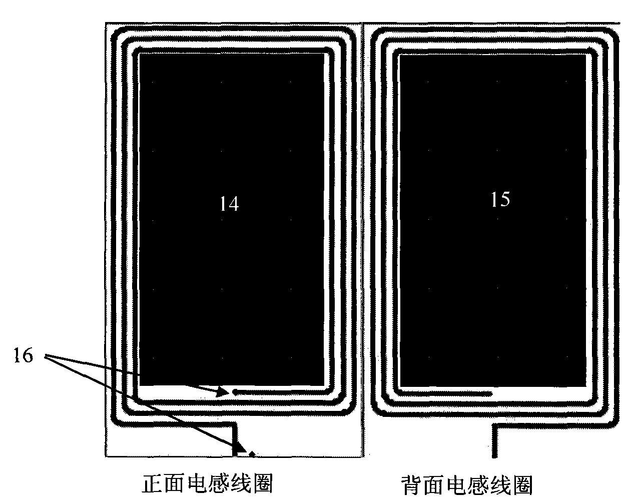
图2是本实用新型具体实施方式的正面电感线圈对背面电感线圈直接馈电的双面电感线圈天线的示意图。Fig. 2 is a schematic diagram of a double-sided inductive coil antenna in which the front inductive coil directly feeds power to the rear inductive coil according to a specific embodiment of the present invention.
具体实施方式 Detailed ways
下面对照附图并结合具体实施方式对本实用新型作一详细说明。The utility model will be described in detail below with reference to the accompanying drawings and in conjunction with specific embodiments.
参见图1-a、图1-b及图2,本实用新型具体实施方式的近场通信天线,在天线底板的正面和背面都设置有电感线圈,采用这种双面电感线圈来减小天线尺寸,而通过在正面线圈和背面线圈的中心都贴覆高磁导率的柔性铁氧体磁芯10、11、12、13、14、15来进一步增强线圈的Q值。Referring to Fig. 1-a, Fig. 1-b and Fig. 2, the near-field communication antenna according to the specific embodiment of the present invention is provided with an inductance coil on the front and back of the antenna base plate, and the double-sided inductance coil is used to reduce the size of the antenna. Size, and the Q value of the coil is further enhanced by pasting high-permeability
双面电感线圈包括有正面线圈对背面线圈直接馈电和不馈电两种形式。以矩形电感线圈为例,图1是正面电感线圈对背面电感线圈不直接馈电形式的双面电感线圈天线的示例图,在图1-a中,正面线圈与背面线圈的绕制方式相同,是正反两面线圈叠加,这种双面电感线圈天线比单面线圈天线在0~10cm的距离内信号增强10%以上。图1-b中,正面线圈与背面线圈的绕制方式是镜像关系,这种双面电感线圈天线比单面线圈天线在0~10cm的距离内信号增强15%以上。Double-sided inductive coils include two forms: the front coil feeds directly to the back coil and does not feed. Taking the rectangular inductance coil as an example, Fig. 1 is an example diagram of a double-sided inductance coil antenna in which the front inductance coil does not directly feed the back inductance coil. In Fig. 1-a, the front coil and the back coil are wound in the same way. The positive and negative coils are superimposed, and the signal of this double-sided inductive coil antenna is more than 10% stronger than that of the single-sided coil antenna within a distance of 0-10cm. In Figure 1-b, the winding method of the front coil and the back coil is a mirror image relationship. Compared with the single-sided coil antenna, the signal of this double-sided inductive coil antenna is increased by more than 15% within a distance of 0-10cm.
图2是正面电感线圈与背面电感线圈通过两个馈电点16直接馈电的双面电感线圈天线的示例图,在本例中,正面线圈与背面线圈绕制方式是镜像关系,这种直接馈电形式的双面电感线圈天线比图1所示不直接馈电形式的天线信号更强,更能进一步减小线圈天线的尺寸。Fig. 2 is the example diagram of the double-sided induction coil antenna that front side induction coil and back side induction coil are directly fed by two
NFC天线包含PCB(印刷电路板)电感线圈天线和FPC电感线圈天线,即天线底板可以是PCB板或者FPC板。线圈天线可以绕制成矩形、圆形、螺旋形等形状。The NFC antenna includes a PCB (printed circuit board) inductive coil antenna and an FPC inductive coil antenna, that is, the antenna bottom plate can be a PCB board or an FPC board. Coil antennas can be wound into rectangular, circular, helical and other shapes.
本实用新型采用双面电感线圈和贴覆高磁导率的柔性铁氧体磁芯的形式来增加线圈天线的电感值和Q值,增大线圈的互感,从而补偿了线圈的小横截面尺寸,因而能够在减小线圈尺寸的基础上,不减小电感和Q值,保证了近场通信距离不会被缩短。The utility model adopts the form of a double-sided inductance coil and a flexible ferrite core covered with high magnetic permeability to increase the inductance value and Q value of the coil antenna, increase the mutual inductance of the coil, and thus compensate the small cross-sectional size of the coil , so the coil size can be reduced without reducing the inductance and Q value, ensuring that the near field communication distance will not be shortened.
本实用新型对于移动终端(手机)、个人数字助理设备(PDA,PersonalDigital Assistant)等安装NFC天线的电子终端设备均适用。The utility model is suitable for electronic terminal equipment installed with NFC antennas such as mobile terminals (mobile phones), personal digital assistant equipment (PDA, Personal Digital Assistant).
以上内容是结合具体的优选实施方式对本实用新型所作的进一步详细说明,不能认定本实用新型的具体实施只局限于这些说明。对于本实用新型所属技术领域的普通技术人员来说,在不脱离本实用新型构思的前提下,还可以做出若干简单推演或替换,都应当视为属于本实用新型的保护范围。The above content is a further detailed description of the utility model in combination with specific preferred embodiments, and it cannot be assumed that the specific implementation of the utility model is only limited to these descriptions. For a person of ordinary skill in the technical field to which the utility model belongs, without departing from the concept of the utility model, some simple deduction or substitutions can also be made, which should be regarded as belonging to the protection scope of the utility model.
Claims (10)
Priority Applications (1)
| Application Number | Priority Date | Filing Date | Title |
|---|---|---|---|
| CNU200820147017XU CN201303054Y (en) | 2008-08-27 | 2008-08-27 | Electronic terminal device and near-field communication antenna thereof |
Applications Claiming Priority (1)
| Application Number | Priority Date | Filing Date | Title |
|---|---|---|---|
| CNU200820147017XU CN201303054Y (en) | 2008-08-27 | 2008-08-27 | Electronic terminal device and near-field communication antenna thereof |
Publications (1)
| Publication Number | Publication Date |
|---|---|
| CN201303054Y true CN201303054Y (en) | 2009-09-02 |
Family
ID=41086684
Family Applications (1)
| Application Number | Title | Priority Date | Filing Date |
|---|---|---|---|
| CNU200820147017XU Expired - Fee Related CN201303054Y (en) | 2008-08-27 | 2008-08-27 | Electronic terminal device and near-field communication antenna thereof |
Country Status (1)
| Country | Link |
|---|---|
| CN (1) | CN201303054Y (en) |
Cited By (21)
| Publication number | Priority date | Publication date | Assignee | Title |
|---|---|---|---|---|
| WO2012088805A1 (en) * | 2010-12-27 | 2012-07-05 | 中兴通讯股份有限公司 | Terminal with near field communication (nfc) antenna |
| CN102646866A (en) * | 2012-04-17 | 2012-08-22 | 中兴通讯股份有限公司 | Near field communication (NFC) antenna and terminal equipment |
| WO2012122743A1 (en) * | 2011-03-11 | 2012-09-20 | 中兴通讯股份有限公司 | Mobile terminal with radio frequency identification function |
| CN102709686A (en) * | 2012-05-14 | 2012-10-03 | 中兴通讯股份有限公司 | Antenna module and mobile terminal equipment |
| CN102820533A (en) * | 2011-06-09 | 2012-12-12 | 上海中京电子标签集成技术有限公司 | Etching antenna |
| CN103208675A (en) * | 2013-03-28 | 2013-07-17 | 华东师范大学 | Near-field coupling-based miniaturized circular multilayer planar helical antenna system |
| CN103762424A (en) * | 2014-01-08 | 2014-04-30 | 深圳顺络电子股份有限公司 | Nfc antenna |
| CN104394267A (en) * | 2014-11-12 | 2015-03-04 | 四川神琥科技有限公司 | A contact-type cell phone evidence collecting and recovering device |
| CN104681990A (en) * | 2013-11-29 | 2015-06-03 | 惠州比亚迪实业有限公司 | NFC (near field communication) antenna and mobile terminal |
| CN105742783A (en) * | 2011-05-31 | 2016-07-06 | 比亚迪股份有限公司 | Near field communication antenna |
| CN105826688A (en) * | 2016-04-26 | 2016-08-03 | 深圳市中天迅通信技术有限公司 | Near field communication antenna device using metal shell |
| CN106025558A (en) * | 2016-07-08 | 2016-10-12 | 上海安费诺永亿通讯电子有限公司 | Stereoscopic NFC structure and electronic equipment with NFC function |
| CN107612578A (en) * | 2017-10-24 | 2018-01-19 | 深圳市前海胜马科技有限公司 | Near-field communication equipment |
| CN112310603A (en) * | 2019-07-30 | 2021-02-02 | Oppo广东移动通信有限公司 | smart watch |
| US11670835B2 (en) | 2008-12-23 | 2023-06-06 | J.J Mackay Canada Limited | Single space wireless parking with improved antenna placements |
| US11699321B2 (en) | 2011-03-03 | 2023-07-11 | J.J Mackay Canada Limited | Parking meter with contactless payment |
| US11762479B2 (en) | 2019-01-30 | 2023-09-19 | J.J. Mackay Canada Limited | SPI keyboard module for a parking meter and a parking meter having an SPI keyboard module |
| US11922756B2 (en) | 2019-01-30 | 2024-03-05 | J.J. Mackay Canada Limited | Parking meter having touchscreen display |
| US11972654B2 (en) | 2015-08-11 | 2024-04-30 | J.J. Mackay Canada Limited | Lightweight vandal resistant parking meter |
| US11978952B2 (en) | 2019-09-04 | 2024-05-07 | Guangdong Oppo Mobile Telecommunications Corp., Ltd. | NFC antenna and NFC communication apparatus for mobile terminal |
| US12417669B2 (en) | 2015-08-08 | 2025-09-16 | J.J. Mackay Canada Limited | Lighweight vandal resistent parking meter |
-
2008
- 2008-08-27 CN CNU200820147017XU patent/CN201303054Y/en not_active Expired - Fee Related
Cited By (26)
| Publication number | Priority date | Publication date | Assignee | Title |
|---|---|---|---|---|
| US12368227B2 (en) | 2008-12-23 | 2025-07-22 | J.J. Mackay Canada Limited | Single space wireless parking with improved antenna placements |
| US11670835B2 (en) | 2008-12-23 | 2023-06-06 | J.J Mackay Canada Limited | Single space wireless parking with improved antenna placements |
| WO2012088805A1 (en) * | 2010-12-27 | 2012-07-05 | 中兴通讯股份有限公司 | Terminal with near field communication (nfc) antenna |
| US12008856B2 (en) | 2011-03-03 | 2024-06-11 | J.J. Mackay Canada Limited | Single space parking meter and removable single space parking meter mechanism |
| US11699321B2 (en) | 2011-03-03 | 2023-07-11 | J.J Mackay Canada Limited | Parking meter with contactless payment |
| US12430978B2 (en) | 2011-03-03 | 2025-09-30 | J.J. Mackay Canada Limited | Parking meter with contactless payment |
| WO2012122743A1 (en) * | 2011-03-11 | 2012-09-20 | 中兴通讯股份有限公司 | Mobile terminal with radio frequency identification function |
| CN105742783A (en) * | 2011-05-31 | 2016-07-06 | 比亚迪股份有限公司 | Near field communication antenna |
| CN102820533A (en) * | 2011-06-09 | 2012-12-12 | 上海中京电子标签集成技术有限公司 | Etching antenna |
| CN102646866A (en) * | 2012-04-17 | 2012-08-22 | 中兴通讯股份有限公司 | Near field communication (NFC) antenna and terminal equipment |
| CN102709686A (en) * | 2012-05-14 | 2012-10-03 | 中兴通讯股份有限公司 | Antenna module and mobile terminal equipment |
| US10014577B2 (en) | 2012-05-14 | 2018-07-03 | Zte Corporation | Aerial module and mobile terminal device |
| CN103208675A (en) * | 2013-03-28 | 2013-07-17 | 华东师范大学 | Near-field coupling-based miniaturized circular multilayer planar helical antenna system |
| CN104681990A (en) * | 2013-11-29 | 2015-06-03 | 惠州比亚迪实业有限公司 | NFC (near field communication) antenna and mobile terminal |
| CN103762424A (en) * | 2014-01-08 | 2014-04-30 | 深圳顺络电子股份有限公司 | Nfc antenna |
| CN104394267A (en) * | 2014-11-12 | 2015-03-04 | 四川神琥科技有限公司 | A contact-type cell phone evidence collecting and recovering device |
| US12417669B2 (en) | 2015-08-08 | 2025-09-16 | J.J. Mackay Canada Limited | Lighweight vandal resistent parking meter |
| US11972654B2 (en) | 2015-08-11 | 2024-04-30 | J.J. Mackay Canada Limited | Lightweight vandal resistant parking meter |
| US11978300B2 (en) | 2015-08-11 | 2024-05-07 | J.J. Mackay Canada Limited | Single space parking meter |
| CN105826688A (en) * | 2016-04-26 | 2016-08-03 | 深圳市中天迅通信技术有限公司 | Near field communication antenna device using metal shell |
| CN106025558A (en) * | 2016-07-08 | 2016-10-12 | 上海安费诺永亿通讯电子有限公司 | Stereoscopic NFC structure and electronic equipment with NFC function |
| CN107612578A (en) * | 2017-10-24 | 2018-01-19 | 深圳市前海胜马科技有限公司 | Near-field communication equipment |
| US11922756B2 (en) | 2019-01-30 | 2024-03-05 | J.J. Mackay Canada Limited | Parking meter having touchscreen display |
| US11762479B2 (en) | 2019-01-30 | 2023-09-19 | J.J. Mackay Canada Limited | SPI keyboard module for a parking meter and a parking meter having an SPI keyboard module |
| CN112310603A (en) * | 2019-07-30 | 2021-02-02 | Oppo广东移动通信有限公司 | smart watch |
| US11978952B2 (en) | 2019-09-04 | 2024-05-07 | Guangdong Oppo Mobile Telecommunications Corp., Ltd. | NFC antenna and NFC communication apparatus for mobile terminal |
Similar Documents
| Publication | Publication Date | Title |
|---|---|---|
| CN201303054Y (en) | Electronic terminal device and near-field communication antenna thereof | |
| US10658870B2 (en) | Combo antenna unit and wireless power receiving module comprising same | |
| CN204442449U (en) | Be applicable to NFC device and the mobile terminal of the mobile terminal with metal edge frame | |
| CN103199333B (en) | A kind of Anneta module supporting NFC and WPC multiplexing | |
| CN105490004B (en) | A kind of mobile terminal antenna system and mobile terminal | |
| CN204441452U (en) | For NFC antenna structure and the intelligent watch of wearable device | |
| US20140306656A1 (en) | Non-contact charging module and portable terminal provided with same | |
| JP2012200136A (en) | Power reception device, and non-contact power supply system and radio communication system having the same | |
| CN102074788A (en) | NFC (Near Field Communication) antenna and mobile phone using same | |
| JP2013146050A (en) | Antenna device and electronic apparatus | |
| CN106898883A (en) | Near-field communication NFC antenna and mobile terminal | |
| CN202617115U (en) | NFC (Near Field Communication) communication module | |
| CN204947083U (en) | A kind of NFC antenna structure of metal back cover | |
| CN206532876U (en) | Antenna based on coil-type | |
| WO2021140692A1 (en) | Wireless power reception device with short-range wireless communication function | |
| CN202217780U (en) | Antenna and mobile terminal for short-distance wireless communication | |
| CN204614924U (en) | Near Field Communication Antenna Assembly and Wireless Terminal | |
| JP2011066759A (en) | Antenna device and communication device | |
| CN205355239U (en) | Three -dimensional NFC antenna under fluting metallic structure environment | |
| CN203423688U (en) | Device having functions of near and far field wireless communication and wireless charging | |
| CN201663226U (en) | Near-field wireless communication antenna device and mobile terminal | |
| CN103886359A (en) | Mobile phone card with radio frequency identification function | |
| CN203103494U (en) | Antenna for NFC (near field communication) smart electric meter | |
| CN202059452U (en) | Mobile terminal possessing radio frequency identification function | |
| CN206341257U (en) | Intelligent mobile terminal and its multi-functional back splint |
Legal Events
| Date | Code | Title | Description |
|---|---|---|---|
| C14 | Grant of patent or utility model | ||
| GR01 | Patent grant | ||
| CF01 | Termination of patent right due to non-payment of annual fee | ||
| CF01 | Termination of patent right due to non-payment of annual fee |
Granted publication date: 20090902 Termination date: 20170827 |