CN201175391Y - knee prosthesis - Google Patents
knee prosthesis Download PDFInfo
- Publication number
- CN201175391Y CN201175391Y CNU2008200618339U CN200820061833U CN201175391Y CN 201175391 Y CN201175391 Y CN 201175391Y CN U2008200618339 U CNU2008200618339 U CN U2008200618339U CN 200820061833 U CN200820061833 U CN 200820061833U CN 201175391 Y CN201175391 Y CN 201175391Y
- Authority
- CN
- China
- Prior art keywords
- tibial
- condyle
- knee
- intercondylar
- femoral prosthesis
- Prior art date
- Legal status (The legal status is an assumption and is not a legal conclusion. Google has not performed a legal analysis and makes no representation as to the accuracy of the status listed.)
- Expired - Fee Related
Links
- 210000003127 knee Anatomy 0.000 title abstract description 39
- 210000000629 knee joint Anatomy 0.000 claims abstract description 46
- 210000002303 tibia Anatomy 0.000 claims abstract description 14
- 210000000689 upper leg Anatomy 0.000 claims abstract description 6
- 230000002093 peripheral effect Effects 0.000 claims description 8
- 238000012856 packing Methods 0.000 claims 1
- 238000005452 bending Methods 0.000 abstract description 7
- 238000005096 rolling process Methods 0.000 abstract description 2
- 210000000988 bone and bone Anatomy 0.000 description 4
- 239000007769 metal material Substances 0.000 description 4
- 210000003041 ligament Anatomy 0.000 description 3
- 239000000463 material Substances 0.000 description 3
- 238000000034 method Methods 0.000 description 3
- 210000004872 soft tissue Anatomy 0.000 description 3
- 208000027418 Wounds and injury Diseases 0.000 description 2
- 230000006378 damage Effects 0.000 description 2
- 208000014674 injury Diseases 0.000 description 2
- 239000000602 vitallium Substances 0.000 description 2
- 241001669060 Astyanax anterior Species 0.000 description 1
- 239000004699 Ultra-high molecular weight polyethylene Substances 0.000 description 1
- 230000015572 biosynthetic process Effects 0.000 description 1
- 230000007812 deficiency Effects 0.000 description 1
- 238000010586 diagram Methods 0.000 description 1
- 201000010099 disease Diseases 0.000 description 1
- 208000037265 diseases, disorders, signs and symptoms Diseases 0.000 description 1
- 238000005516 engineering process Methods 0.000 description 1
- 239000000203 mixture Substances 0.000 description 1
- 230000036285 pathological change Effects 0.000 description 1
- 231100000915 pathological change Toxicity 0.000 description 1
- 229920000785 ultra high molecular weight polyethylene Polymers 0.000 description 1
Images


Landscapes
- Prostheses (AREA)
Abstract
本实用新型提供一种膝关节内用假体,该假体包括:与股骨远端连接的股骨假体1,固定在胫骨支座5上的胫骨衬垫4,与胫骨近端连接的胫骨支座5,装入胫骨衬垫4髁间孔4c内和胫骨支座5凸台5f孔内的胫骨髁间嵴3,保证胫骨髁间嵴3与胫骨衬垫4和胫骨支座5相对位置的螺钉2。胫骨衬垫4的内骨髁4a和外骨髁4b关节面分别与股骨假体1的内骨髁1a和外骨髁1b关节面对应,以保证股骨假体1可以在胫骨衬垫4上实现伸屈和滚后动作。胫骨髁间嵴3伸入股骨假体的髁间区域1d内,以保证膝关节的伸膝稳定性,胫骨髁间嵴3靠近于股骨假体1外骨髁1b的部份被切除,以保证股骨假体1在屈膝位时有更大的外旋角度,从而实现膝关节深度屈曲。
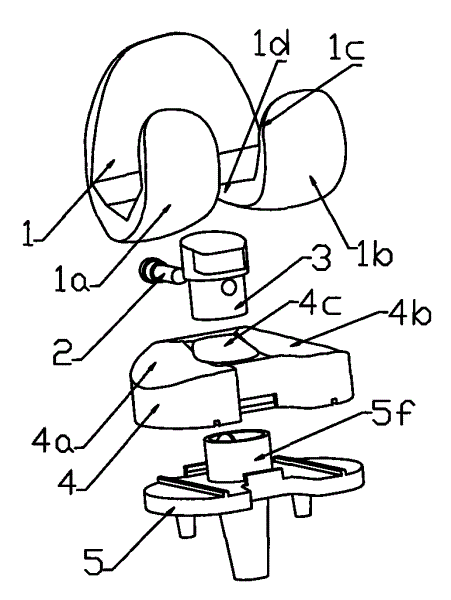
The utility model provides an internal prosthesis for the knee joint, which comprises: a femoral prosthesis 1 connected with the distal end of the femur, a tibial liner 4 fixed on the tibial bearing 5, and a tibial ramus connected with the proximal end of the tibia Seat 5 is packed into tibial intercondylar crest 3 in tibial pad 4 intercondylar hole 4c and tibial bearing 5 boss 5f hole to ensure the relative position of tibial intercondylar crest 3 and tibial pad 4 and tibial bearing 5 screw 2. The inner condyle 4a of the tibial pad 4 and the articular surface of the outer condyle 4b correspond to the articular surface of the inner condyle 1a and the outer condyle 1b of the femoral prosthesis 1 respectively, to ensure that the femoral prosthesis 1 can be stretched on the tibial pad 4. After bending and rolling. The tibial intercondylar ridge 3 extends into the intercondylar area 1d of the femoral prosthesis to ensure the stability of the knee joint. Prosthesis 1 has a greater angle of external rotation in knee flexion, thereby achieving deep knee flexion.
Description
技术领域 technical field
本实用新型涉及一种医用人工关节,尤其涉及一种应用于人体的膝关节内用假体,在膝关节成形中,用来替换由于病变或损伤等原因造成全部或部分功能丧失的人体自然膝关节。The utility model relates to a medical artificial joint, in particular to a knee prosthesis applied to the human body, which is used to replace the human body's natural knee which has lost all or part of its function due to pathological changes or injuries during the formation of the knee joint. joint.
背景技术 Background technique
人工膝关节的发展距今已有40余年的历史,当人体自然膝关节由于病变或损伤等原因造成全部或部分功能丧失时,就需要用人工膝关节予以替换,以重建膝关节,减轻病人的病痛。The development of artificial knee joints has a history of more than 40 years. When the natural knee joint of the human body loses all or part of its function due to disease or injury, it needs to be replaced with an artificial knee joint to reconstruct the knee joint and reduce the patient's pain. illness.
通常所说的膝关节内用假体包括股骨假体和胫骨假体两大部分。其中,股骨假体通过股骨安装茎或螺钉与股骨远端连接,具有内骨髁和外骨髁。胫骨假体分为胫骨衬垫和胫骨支座两部分,胫骨支座固定在胫骨近端,胫骨衬垫位于股骨假体和胫骨支座之间,固定在胫骨支座上,其内外骨髁关节面分别与股骨假体内外骨髁关节面相匹配,以模拟正常的人体自然膝关节运动过程。The so-called internal prosthesis of the knee joint includes two parts: the femoral prosthesis and the tibial prosthesis. Among them, the femoral prosthesis is connected to the distal end of the femur through a femoral mounting stem or screws, and has inner and outer condyles. The tibial prosthesis is divided into two parts, the tibial bearing and the tibial bearing. The tibial bearing is fixed at the proximal end of the tibia. The tibial lining is located between the femoral prosthesis and the tibial bearing and is fixed on the tibial bearing. The surfaces are respectively matched with the articular surfaces of the inner and outer condyles of the femoral prosthesis to simulate the normal natural knee joint movement process of the human body.
对于人体自然膝关节而言,当膝关节从处于伸膝位时,胫骨髁间嵴伸入股骨髁间凹槽内,与周围韧带和软组织共同实现了膝关节的稳定性,当膝关节从伸膝位开始逐渐屈膝时,股骨相对胫骨的外旋角度逐渐增加。于是,在膝关节内用假体中,设计胫骨髁间嵴以实现膝关节的伸膝位稳定性,同时,胫骨髁间嵴可以增加股骨假体相对胫骨假体的外旋角度,以增加膝关节的弯曲角度。在美国专利US6793680中,提出了胫骨髁间嵴的一种新型式,其胫骨髁间嵴在膝关节前侧部分凸出,以实现膝关节的伸膝位稳定性,在后侧部分凹下,以增加屈膝时股骨假体相对胫骨假体的外旋角度。在美国专利US7066963,US6902582中,胫骨髁间嵴前侧部分高于后侧部分,一方面实现膝关节的伸膝位稳定性,另一方面增加屈膝时股骨假体相对胫骨假体的外旋角度。但这些专利中的胫骨髁间嵴与胫骨衬垫都是一个整体,当胫骨髁间嵴的磨损增加时,整个胫骨衬垫的寿命就会降低,从而影响膝关节内用假体的运动稳定性。For the human natural knee joint, when the knee joint is in the knee extension position, the tibial intercondylar ridge extends into the femoral intercondylar groove, and together with the surrounding ligaments and soft tissues, it realizes the stability of the knee joint. As the knee begins to gradually flex, the external rotation angle of the femur relative to the tibia gradually increases. Therefore, in the internal prosthesis of the knee joint, the tibial intercondylar crest is designed to achieve the stability of the knee joint in extensor position. The bending angle of the joint. In U.S. Patent US6793680, a new type of tibial intercondylar ridge is proposed, the tibial intercondylar ridge protrudes on the front side of the knee joint to achieve the stability of the knee joint in extension, and is concave on the back side. To increase the external rotation of the femoral component relative to the tibial component during knee flexion. In U.S. Patent No. 7,066,963 and U.S. Pat. No. 6,902,582, the anterior part of the tibial intercondylar ridge is higher than the posterior part, on the one hand, the stability of the knee joint can be achieved, and on the other hand, the external rotation angle of the femoral prosthesis relative to the tibial prosthesis can be increased when the knee is flexed . However, the tibial intercondylar ridge and the tibial liner in these patents are integrated. When the wear of the tibial intercondylar ridge increases, the life of the entire tibial liner will be reduced, thereby affecting the stability of the knee prosthesis. .
发明内容 Contents of the invention
针对以上技术和专利的不足,本实用新型提出一种新的人体膝关节内用假体,目的在于:首先,当膝关节从处于伸膝位时,胫骨髁间嵴伸入股骨髁间凹槽内,与周围韧带和软组织共同实现膝关节的稳定性。其次,胫骨髁间嵴可以增加股骨假体相对胫骨假体的外旋角度,以增加膝关节的弯曲角度,并实现膝关节深度屈曲。最后,胫骨髁间嵴与胫骨衬垫分离设计,胫骨髁间嵴采用耐磨金属材料制成,以提高胫骨假体髁间嵴的耐磨性能,进而保证膝关节内用假体的运动稳定性。Aiming at the deficiencies of the above technologies and patents, the utility model proposes a new human knee prosthesis for internal use. The purpose is: firstly, when the knee joint is in the knee extension position, the tibial intercondylar ridge extends into the femoral intercondylar groove Inside, it works with the surrounding ligaments and soft tissues to stabilize the knee joint. Secondly, the tibial intercondylar ridge can increase the external rotation angle of the femoral component relative to the tibial component, so as to increase the bending angle of the knee joint and achieve deep knee flexion. Finally, the tibial intercondylar crest and the tibial pad are designed separately, and the tibial intercondylar crest is made of wear-resistant metal materials to improve the wear resistance of the tibial prosthetic intercondylar crest, thereby ensuring the stability of the knee prosthesis .
本实用新型中所述的膝关节内用假体适用于膝关节周围韧带和软组织功能完好的病人。The knee prosthesis described in the utility model is suitable for patients with intact ligaments and soft tissues around the knee joint.
该装置的具体构成:The specific composition of the device:
股骨假体1,该假体与股骨远端连接,具有内骨髁1a、外骨髁1b和髁间区域1d;Femoral prosthesis 1, this prosthesis is connected with femur distal end, has inner bone condyle 1a,
胫骨支座5,该支座与胫骨近端连接;Tibial bearing 5, which is connected with the proximal end of the tibia;
胫骨衬垫4,该衬垫固定在胫骨支座5上,具有内骨髁4a和外骨髁4b;The
胫骨髁间嵴3,装入胫骨衬垫4髁间孔4c内和胫骨支座5凸台5f孔内,顶部周界由面3a、3b、3c、3d、3e组成,,其中3e为斜面;The tibial intercondylar ridge 3 is put into the
螺钉2,与胫骨衬垫4的髁间孔4c和胫骨支座5的凸台5f相连。The
该装置实施的技术方案:The technical scheme implemented by the device:
当膝关节由屈膝位逐渐到伸膝位时,胫骨髁间嵴3逐渐伸入股骨假体的髁间区域1a内,其顶部周界面3a、3b、3c、3d与股骨假体髁间区域1d相配合,以保证膝关节的伸膝稳定性。When the knee joint is gradually extended from the knee flexion position to the knee extension position, the tibial intercondylar ridge 3 gradually extends into the intercondylar area 1a of the femoral prosthesis, and its top peripheral interfaces 3a, 3b, 3c, 3d are in contact with the intercondylar area 1d of the femoral prosthesis. Cooperate with each other to ensure the stability of knee extension.
当膝关节的弯曲角度逐渐增加时,股骨假体1的外旋角度逐渐增加,胫骨髁间嵴3靠近于股骨假体1外骨髁1b的部份被切除,即胫骨髁间嵴3的顶部周界面3e为斜面,且3e与竖直线T的逆时针夹角为B,此时,股骨假体1外骨髁1b的后侧部分1c不会与胫骨髁间嵴3干涉,从而保证股骨假体1在屈膝位时有更大的外旋角度,以增加膝关节的弯曲角度,并最终实现膝关节深度屈曲。When the bending angle of the knee joint increases gradually, the external rotation angle of the femoral prosthesis 1 gradually increases, and the part of the tibial intercondylar ridge 3 close to the
本实用新型的优点是:首先,可实现膝关节的伸膝稳定性。其次,股骨假体相对胫骨假体的外旋角度增加,可增加膝关节的弯曲角度并实现膝关节深度屈曲。最后,胫骨髁间嵴采用耐磨金属材料制成,这不仅可提高膝关节内用假体的整体寿命,而且可保证膝关节内用假体的运动稳定性。The utility model has the advantages that: firstly, the knee extension stability of the knee joint can be realized. Second, the increased external rotation of the femoral component relative to the tibial component increases the knee flexion angle and enables deep knee flexion. Finally, the tibial intercondylar ridge is made of wear-resistant metal material, which not only improves the overall lifespan of the knee endoprosthesis, but also ensures the stability of the knee endoprosthesis in motion.
附图说明 Description of drawings
图1膝关节内用假体分解透视图Fig.1 Exploded perspective view of internal prosthesis of knee joint
图2胫骨假体主视图Figure 2 Front view of the tibial prosthesis
图3关于图2中剖面线K-K的剖视图Fig. 3 is a cross-sectional view about section line K-K in Fig. 2
图4关于图2中剖面线H-H的剖视图Figure 4 is a cross-sectional view of the section line H-H in Figure 2
图5关于胫骨髁间嵴的对称实例图Figure 5 Symmetry example diagram about tibial intercondylar ridge
图中序号,1.股骨假体,2.螺钉,3.胫骨髁间嵴,4.胫骨衬垫,5.胫骨支座A.膝关节前侧,P.膝关节后侧,M.膝关节内侧,L.膝关节外侧Serial number in the picture, 1. Femoral prosthesis, 2. Screw, 3. Tibial intercondylar ridge, 4. Tibial liner, 5. Tibial bearing A. Anterior side of knee joint, P. Posterior side of knee joint, M. Knee joint Medial, L. Lateral of the knee joint
具体实施方式 Detailed ways
在图1、图2、图3和图4中,股骨假体1由钴-铬-钼合金材料制成,通过股骨安装茎或螺钉与股骨远端连接,具有内骨髁1a和外骨髁1b。胫骨支座5由钴-铬-钼合金材料制成,通过胫骨安装茎5c和固定柱5b、5d与胫骨近端连接,其中,胫骨安装茎5c压入胫骨髓腔,起主要固定作用,固定柱5b、5d压入胫骨近端切骨面,起防转和辅助固定作用。胫骨衬垫4由超高分子量聚乙烯材料制成,位于股骨假体1和胫骨支座5之间,具有内骨髁4a和外骨髁4b,通过沿胫骨支座A-P方向(前-后方向)的凸起5a和5e实现胫骨衬垫4沿M-L方向(内-外方向)的定位,通过胫骨衬垫4上沿A-P方向(前-后方向)卡口面4c、4d与胫骨支座5沿A-P方向(前-后方向)卡口面5h、5j的配合实现胫骨衬垫4沿A-P方向(前-后方向)的定位和同定,同时,可防止胫骨衬垫4向上脱位。胫骨髁间嵴3由耐磨金属材料制成,装入胫骨衬垫4髁间孔4c内和胫骨支座5凸台5f孔内。螺钉2的2b部分伸入胫骨髁间嵴3的相应孔,实现髁间嵴3和胫骨衬垫4与胫骨支座5的相对位置定位,螺钉2的2a部分为外螺纹,与胫骨衬垫4的相应螺纹孔连接,实现髁间嵴3和胫骨衬垫4与胫骨支座5的相对位置固定。In Fig. 1, Fig. 2, Fig. 3 and Fig. 4, the femoral prosthesis 1 is made of cobalt-chromium-molybdenum alloy material, connected with the distal end of the femur through femoral mounting stems or screws, and has inner condyle 1a and
在图1中,当膝关节由屈膝位逐渐到伸膝位,或由伸膝位逐渐到屈膝位时,股骨假体1的内骨髁1a关节面和外骨髁1b关节面分别与胫骨衬垫4的内骨髁4a关节面和外骨髁4b关节面相匹配,以实现股骨假体1在胫骨衬垫4上的弯曲、滑动和滚后等动作,从而模拟正常的人体自然膝关节运动过程In Fig. 1, when the knee joint gradually moves from the knee flexion position to the knee extension position, or from the knee extension position to the knee flexion position gradually, the articular surface of the medial condyle 1a and the articular surface of the
在图1和图2中,当膝关节由屈膝位逐渐到伸膝位时,胫骨髁间嵴3逐渐伸入股骨假体的髁间区域1d内,其顶部周界面3a、3b、3c、3d与股骨假体髁间区域1d相配合,以保证膝关节的伸膝稳定性。In Figures 1 and 2, when the knee joint gradually moves from the knee flexion position to the knee extension position, the tibial intercondylar ridge 3 gradually extends into the intercondylar region 1d of the femoral prosthesis, and its top peripheral surfaces 3a, 3b, 3c, 3d It cooperates with the intercondylar area 1d of the femoral prosthesis to ensure the stability of the knee joint in extension.
在图1和图2中,当膝关节由伸膝位逐渐屈膝,并随着弯曲角度逐渐增加时,股骨假体1沿着图2中所示R方向相对胫骨衬垫4进行外旋,且外旋角度逐渐增加,胫骨髁间嵴3靠近于股骨假体1外骨髁1b的部份被切除,即胫骨髁间嵴3的顶部周界面3e为斜面,且3e与竖直线T的逆时针夹角为B,此时,股骨假体1外骨髁1b的后侧部分1c不会与胫骨髁间嵴3干涉,从而保证股骨假体1在屈膝位时有更大的外旋角度,以增加膝关节的弯曲角度,并最终实现膝关节深度屈曲。夹角B的大小可以进行选择,从而可根据病人的实际情况置入最合适的胫骨髁间嵴3。In Fig. 1 and Fig. 2, when the knee joint gradually bends from the knee extension position, and gradually increases with the bending angle, the femoral prosthesis 1 is externally rotated relative to the
胫骨髁间嵴3或3’采用耐磨金属材料制成,于是,在膝关节由屈膝位逐渐到伸膝位,或由伸膝位逐渐到屈膝位时,胫骨髁间嵴3或3’相对于股骨假体1的磨损量大大降低,这不仅可提高膝关节内用假体的整体寿命,而且可保证膝关节内用假体的运动稳定性。The tibial intercondylar crest 3 or 3' is made of wear-resistant metal material, so when the knee joint gradually moves from the knee flexion position to the knee extension position, or gradually from the knee extension position to the knee flexion position, the tibial intercondylar crest 3 or 3' is relatively The wear amount of the femoral prosthesis 1 is greatly reduced, which can not only improve the overall lifespan of the knee joint internal prosthesis, but also ensure the motion stability of the knee joint internal prosthesis.
图1、图2、图3和图4中所示膝关节内用假体适用于右侧膝关节。The knee prosthesis shown in Figure 1, Figure 2, Figure 3 and Figure 4 is suitable for the right knee joint.
在图2中,把胫骨髁间嵴3换为图5所示的胫骨髁间嵴对称实例3’,本文所述的膝关节内用假体同样也可适用于左侧膝关节。In Fig. 2, the tibial intercondylar crest 3 is replaced by the tibial intercondylar crest symmetry example 3' shown in Fig. 5, and the knee prosthesis described herein is also applicable to the left knee joint.
Claims (3)
Priority Applications (1)
| Application Number | Priority Date | Filing Date | Title |
|---|---|---|---|
| CNU2008200618339U CN201175391Y (en) | 2008-01-17 | 2008-01-17 | knee prosthesis |
Applications Claiming Priority (1)
| Application Number | Priority Date | Filing Date | Title |
|---|---|---|---|
| CNU2008200618339U CN201175391Y (en) | 2008-01-17 | 2008-01-17 | knee prosthesis |
Publications (1)
| Publication Number | Publication Date |
|---|---|
| CN201175391Y true CN201175391Y (en) | 2009-01-07 |
Family
ID=40215404
Family Applications (1)
| Application Number | Title | Priority Date | Filing Date |
|---|---|---|---|
| CNU2008200618339U Expired - Fee Related CN201175391Y (en) | 2008-01-17 | 2008-01-17 | knee prosthesis |
Country Status (1)
| Country | Link |
|---|---|
| CN (1) | CN201175391Y (en) |
Cited By (24)
| Publication number | Priority date | Publication date | Assignee | Title |
|---|---|---|---|---|
| WO2010096960A1 (en) * | 2009-02-25 | 2010-09-02 | 北京纳通投资有限公司 | Artificial knee replacement prostheses with anterior cruciate ligament reserved or reconstructed |
| CN102497837A (en) * | 2009-07-27 | 2012-06-13 | 托马斯·P·安瑞尔基 | Knee replacement system and method for enabling natural knee movement |
| CN102860887A (en) * | 2012-09-17 | 2013-01-09 | 青岛城阳古镇正骨医院 | Movable joint spacer for infection after total knee replacement |
| CN103565559A (en) * | 2012-08-03 | 2014-02-12 | 北京大学人民医院 | Double-acting type artificial knee joint prosthesis |
| CN104093380A (en) * | 2011-11-21 | 2014-10-08 | 捷迈有限公司 | Tibial baseplate with asymmetrically placed fixation structures |
| CN105246432A (en) * | 2013-05-30 | 2016-01-13 | 优罗斯公司 | Improvement of total knee prosthesis and its assembly method |
| US9295557B2 (en) | 2010-07-24 | 2016-03-29 | Zimmer, Inc. | Asymmetric tibial components for a knee prosthesis |
| US9314343B2 (en) | 2010-09-10 | 2016-04-19 | Zimmer, Inc. | Motion facilitating tibial components for a knee prosthesis |
| US9381090B2 (en) | 2010-07-24 | 2016-07-05 | Zimmer, Inc. | Asymmetric tibial components for a knee prosthesis |
| US9763794B2 (en) | 2010-07-24 | 2017-09-19 | Zimmer, Inc. | Tibial prosthesis |
| CN107518965A (en) * | 2016-11-30 | 2017-12-29 | 嘉思特华剑医疗器材(天津)有限公司 | Radially constrain rotatable platform articular surface knee-joint prosthesis |
| CN109199647A (en) * | 2017-07-03 | 2019-01-15 | 天津富华医疗科技有限公司 | Half condyle formula artificial knee joint |
| US10188530B2 (en) | 2010-12-17 | 2019-01-29 | Zimmer, Inc. | Provisional tibial prosthesis system |
| US10278827B2 (en) | 2015-09-21 | 2019-05-07 | Zimmer, Inc. | Prosthesis system including tibial bearing component |
| CN110051456A (en) * | 2018-01-19 | 2019-07-26 | 苏州微创关节医疗科技有限公司 | Modularization bends and stretches clearance checking scale/tibial prosthesis die trial |
| CN110680570A (en) * | 2019-10-21 | 2020-01-14 | 北京安颂科技有限公司 | Tibial prosthesis locking component and artificial knee joint prosthesis |
| CN111214313A (en) * | 2018-11-27 | 2020-06-02 | 南京埃利莎生物技术有限公司 | Bionic buffer system of artificial joint and bionic artificial joint adopting bionic buffer system |
| US10675153B2 (en) | 2017-03-10 | 2020-06-09 | Zimmer, Inc. | Tibial prosthesis with tibial bearing component securing feature |
| US10835380B2 (en) | 2018-04-30 | 2020-11-17 | Zimmer, Inc. | Posterior stabilized prosthesis system |
| US10898337B2 (en) | 2011-11-18 | 2021-01-26 | Zimmer, Inc. | Tibial bearing component for a knee prosthesis with improved articular characteristics |
| CN112741713A (en) * | 2019-10-31 | 2021-05-04 | 苏州微创关节医疗科技有限公司 | Tibial prosthesis and knee joint prosthesis |
| US11324598B2 (en) | 2013-08-30 | 2022-05-10 | Zimmer, Inc. | Method for optimizing implant designs |
| US11324599B2 (en) | 2017-05-12 | 2022-05-10 | Zimmer, Inc. | Femoral prostheses with upsizing and downsizing capabilities |
| US11426282B2 (en) | 2017-11-16 | 2022-08-30 | Zimmer, Inc. | Implants for adding joint inclination to a knee arthroplasty |
-
2008
- 2008-01-17 CN CNU2008200618339U patent/CN201175391Y/en not_active Expired - Fee Related
Cited By (48)
| Publication number | Priority date | Publication date | Assignee | Title |
|---|---|---|---|---|
| WO2010096960A1 (en) * | 2009-02-25 | 2010-09-02 | 北京纳通投资有限公司 | Artificial knee replacement prostheses with anterior cruciate ligament reserved or reconstructed |
| CN102497837B (en) * | 2009-07-27 | 2015-12-02 | 托马斯·P·安瑞尔基 | knee replacement system |
| CN102497837A (en) * | 2009-07-27 | 2012-06-13 | 托马斯·P·安瑞尔基 | Knee replacement system and method for enabling natural knee movement |
| US10307256B2 (en) | 2009-07-27 | 2019-06-04 | Biomet Manufacturing, Llc | Knee replacement system and method for enabling natural knee movement |
| US9314342B2 (en) | 2009-07-27 | 2016-04-19 | Biomet Manufacturing, Llc | Knee replacement system and method for enabling natural knee movement |
| US9295557B2 (en) | 2010-07-24 | 2016-03-29 | Zimmer, Inc. | Asymmetric tibial components for a knee prosthesis |
| US9861490B2 (en) | 2010-07-24 | 2018-01-09 | Zimmer, Inc. | Asymmetric tibial components for a knee prosthesis |
| US11224519B2 (en) | 2010-07-24 | 2022-01-18 | Zimmer, Inc. | Asymmetric tibial components for a knee prosthesis |
| US10195041B2 (en) | 2010-07-24 | 2019-02-05 | Zimmer, Inc. | Asymmetric tibial components for a knee prosthesis |
| US10543099B2 (en) | 2010-07-24 | 2020-01-28 | Zimmer, Inc. | Tibial prosthesis |
| US12239540B2 (en) | 2010-07-24 | 2025-03-04 | Zimmer, Inc. | Asymmetric tibial components for a knee prosthesis |
| US9381090B2 (en) | 2010-07-24 | 2016-07-05 | Zimmer, Inc. | Asymmetric tibial components for a knee prosthesis |
| US10470889B2 (en) | 2010-07-24 | 2019-11-12 | Zimmer, Inc. | Asymmetric tibial components for a knee prosthesis |
| US9918844B2 (en) | 2010-07-24 | 2018-03-20 | Zimmer, Inc. | Tibial prosthesis with a fixed bearing component |
| US9763796B2 (en) | 2010-07-24 | 2017-09-19 | Zimmer, Inc. | Asymmetric tibial components for a knee prosthesis |
| US9763794B2 (en) | 2010-07-24 | 2017-09-19 | Zimmer, Inc. | Tibial prosthesis |
| US9763795B2 (en) | 2010-09-10 | 2017-09-19 | Zimmer, Inc. | Motion facilitating tibial components for a knee prosthesis |
| US11471288B2 (en) | 2010-09-10 | 2022-10-18 | Zimmer, Inc. | Motion facilitating tibial components for a knee prosthesis |
| US10413415B2 (en) | 2010-09-10 | 2019-09-17 | Zimmer, Inc. | Motion facilitating tibial components for a knee prosthesis |
| US9314343B2 (en) | 2010-09-10 | 2016-04-19 | Zimmer, Inc. | Motion facilitating tibial components for a knee prosthesis |
| US10188530B2 (en) | 2010-12-17 | 2019-01-29 | Zimmer, Inc. | Provisional tibial prosthesis system |
| US12383407B2 (en) | 2011-11-18 | 2025-08-12 | Zimmer, Inc. | Tibial bearing component for a knee prosthesis with improved articular characteristics |
| US10898337B2 (en) | 2011-11-18 | 2021-01-26 | Zimmer, Inc. | Tibial bearing component for a knee prosthesis with improved articular characteristics |
| CN104093380B (en) * | 2011-11-21 | 2016-08-31 | 捷迈有限公司 | Tibial baseplate with asymmetrically placed fixation structures |
| US10265181B2 (en) | 2011-11-21 | 2019-04-23 | Zimmer, Inc. | Tibial baseplate with asymmetric placement of fixation structures |
| US9707089B2 (en) | 2011-11-21 | 2017-07-18 | Zimmer, Inc. | Tibial baseplate with asymmetric placement of fixation structures |
| CN104093380A (en) * | 2011-11-21 | 2014-10-08 | 捷迈有限公司 | Tibial baseplate with asymmetrically placed fixation structures |
| CN103565559A (en) * | 2012-08-03 | 2014-02-12 | 北京大学人民医院 | Double-acting type artificial knee joint prosthesis |
| CN103565559B (en) * | 2012-08-03 | 2015-08-26 | 北京大学人民医院 | A kind of two ejector half artificial knee joint prosthesis |
| CN102860887A (en) * | 2012-09-17 | 2013-01-09 | 青岛城阳古镇正骨医院 | Movable joint spacer for infection after total knee replacement |
| CN105246432A (en) * | 2013-05-30 | 2016-01-13 | 优罗斯公司 | Improvement of total knee prosthesis and its assembly method |
| US11324598B2 (en) | 2013-08-30 | 2022-05-10 | Zimmer, Inc. | Method for optimizing implant designs |
| US10278827B2 (en) | 2015-09-21 | 2019-05-07 | Zimmer, Inc. | Prosthesis system including tibial bearing component |
| US11160659B2 (en) | 2015-09-21 | 2021-11-02 | Zimmer, Inc. | Prosthesis system including tibial bearing component |
| CN107518965A (en) * | 2016-11-30 | 2017-12-29 | 嘉思特华剑医疗器材(天津)有限公司 | Radially constrain rotatable platform articular surface knee-joint prosthesis |
| US11547571B2 (en) | 2017-03-10 | 2023-01-10 | Zimmer, Inc. | Tibial prosthesis with tibial bearing component securing feature |
| US10675153B2 (en) | 2017-03-10 | 2020-06-09 | Zimmer, Inc. | Tibial prosthesis with tibial bearing component securing feature |
| US12458502B2 (en) | 2017-03-10 | 2025-11-04 | Zimmer, Inc. | Tibial prosthesis with tibial bearing component securing feature |
| US11324599B2 (en) | 2017-05-12 | 2022-05-10 | Zimmer, Inc. | Femoral prostheses with upsizing and downsizing capabilities |
| CN109199647A (en) * | 2017-07-03 | 2019-01-15 | 天津富华医疗科技有限公司 | Half condyle formula artificial knee joint |
| US11426282B2 (en) | 2017-11-16 | 2022-08-30 | Zimmer, Inc. | Implants for adding joint inclination to a knee arthroplasty |
| CN110051456A (en) * | 2018-01-19 | 2019-07-26 | 苏州微创关节医疗科技有限公司 | Modularization bends and stretches clearance checking scale/tibial prosthesis die trial |
| CN110051456B (en) * | 2018-01-19 | 2024-01-19 | 苏州微创关节医疗科技有限公司 | Modularized flexion-extension clearance measurer/tibia prosthesis test mould |
| US10835380B2 (en) | 2018-04-30 | 2020-11-17 | Zimmer, Inc. | Posterior stabilized prosthesis system |
| US11911279B2 (en) | 2018-04-30 | 2024-02-27 | Zimmer, Inc. | Posterior stabilized prosthesis system |
| CN111214313A (en) * | 2018-11-27 | 2020-06-02 | 南京埃利莎生物技术有限公司 | Bionic buffer system of artificial joint and bionic artificial joint adopting bionic buffer system |
| CN110680570A (en) * | 2019-10-21 | 2020-01-14 | 北京安颂科技有限公司 | Tibial prosthesis locking component and artificial knee joint prosthesis |
| CN112741713A (en) * | 2019-10-31 | 2021-05-04 | 苏州微创关节医疗科技有限公司 | Tibial prosthesis and knee joint prosthesis |
Similar Documents
| Publication | Publication Date | Title |
|---|---|---|
| CN201175391Y (en) | knee prosthesis | |
| CN101214175A (en) | knee prosthesis | |
| US6893467B1 (en) | Knee prosthesis | |
| JP4559061B2 (en) | Femoral component for knee prosthesis | |
| US7387644B2 (en) | Knee joint prosthesis with a femoral component which links the tibiofemoral axis of rotation with the patellofemoral axis of rotation | |
| US7413577B1 (en) | Total stabilized knee prosthesis with constraint | |
| US11219529B2 (en) | Stabilized total ankle prosthesis | |
| US7922770B2 (en) | Total knee arthroplasty endoprosthesis with third condyle and rotating polyethylene insert | |
| JP5512178B2 (en) | Knee joint prosthesis with improved kinematics | |
| JP5399989B2 (en) | High performance knee prosthesis | |
| US10433970B2 (en) | Prosthetic ankle | |
| JP5410181B2 (en) | Front and rear placement of rotating shaft for rotating platform | |
| EP1696835B1 (en) | Tibial knee prosthesis | |
| EP1974693B1 (en) | Mobile tibial bearing assembly | |
| US3798679A (en) | Joint prostheses | |
| JP4681931B2 (en) | Hinged knee prosthesis | |
| US20090210066A1 (en) | Anterior cruciate ligament substituting knee replacement prosthesis | |
| US20240173138A1 (en) | Cruciate replacing artificial knee | |
| KR102568088B1 (en) | Total knee prosthesis with ceramic on ceramic friction torque and mobile ceramic plate | |
| AU2018279260B2 (en) | Modular knee prosthesis | |
| Ash et al. | Design of a surface replacement prosthesis for the proximal interphalangeal joint | |
| JP2018523497A (en) | Talar implant for changing joint kinematics | |
| Wyss | i, United States Patent (10) Patent No.: US 7.981. 159 B2 |
Legal Events
| Date | Code | Title | Description |
|---|---|---|---|
| C14 | Grant of patent or utility model | ||
| GR01 | Patent grant | ||
| C17 | Cessation of patent right | ||
| CF01 | Termination of patent right due to non-payment of annual fee |
Granted publication date: 20090107 Termination date: 20120117 |