CN201113096Y - electrical connector - Google Patents
electrical connector Download PDFInfo
- Publication number
- CN201113096Y CN201113096Y CNU200720183072XU CN200720183072U CN201113096Y CN 201113096 Y CN201113096 Y CN 201113096Y CN U200720183072X U CNU200720183072X U CN U200720183072XU CN 200720183072 U CN200720183072 U CN 200720183072U CN 201113096 Y CN201113096 Y CN 201113096Y
- Authority
- CN
- China
- Prior art keywords
- terminal
- connector
- upper wall
- electric connector
- terminals
- Prior art date
- Legal status (The legal status is an assumption and is not a legal conclusion. Google has not performed a legal analysis and makes no representation as to the accuracy of the status listed.)
- Expired - Fee Related
Links
Images


Classifications
-
- H—ELECTRICITY
- H01—ELECTRIC ELEMENTS
- H01R—ELECTRICALLY-CONDUCTIVE CONNECTIONS; STRUCTURAL ASSOCIATIONS OF A PLURALITY OF MUTUALLY-INSULATED ELECTRICAL CONNECTING ELEMENTS; COUPLING DEVICES; CURRENT COLLECTORS
- H01R27/00—Coupling parts adapted for co-operation with two or more dissimilar counterparts
-
- H—ELECTRICITY
- H01—ELECTRIC ELEMENTS
- H01R—ELECTRICALLY-CONDUCTIVE CONNECTIONS; STRUCTURAL ASSOCIATIONS OF A PLURALITY OF MUTUALLY-INSULATED ELECTRICAL CONNECTING ELEMENTS; COUPLING DEVICES; CURRENT COLLECTORS
- H01R13/00—Details of coupling devices of the kinds covered by groups H01R12/70 or H01R24/00 - H01R33/00
- H01R13/648—Protective earth or shield arrangements on coupling devices, e.g. anti-static shielding
- H01R13/658—High frequency shielding arrangements, e.g. against EMI [Electro-Magnetic Interference] or EMP [Electro-Magnetic Pulse]
- H01R13/6581—Shield structure
- H01R13/6582—Shield structure with resilient means for engaging mating connector
-
- H—ELECTRICITY
- H01—ELECTRIC ELEMENTS
- H01R—ELECTRICALLY-CONDUCTIVE CONNECTIONS; STRUCTURAL ASSOCIATIONS OF A PLURALITY OF MUTUALLY-INSULATED ELECTRICAL CONNECTING ELEMENTS; COUPLING DEVICES; CURRENT COLLECTORS
- H01R2201/00—Connectors or connections adapted for particular applications
- H01R2201/06—Connectors or connections adapted for particular applications for computer periphery
Landscapes
- Details Of Connecting Devices For Male And Female Coupling (AREA)
- Connector Housings Or Holding Contact Members (AREA)
- Coupling Device And Connection With Printed Circuit (AREA)
Abstract
本实用新型提供一种电连接器,该电连接器包括:本体、若干第一端子和一组第二端子,所述本体包括上壁、与上壁相对的下壁及连接上壁与下壁的一对侧壁,所述上壁、下壁及侧壁围成一收容空间;若干第一端子组装于本体的上壁;第二端子组装于本体上;每一第一端子或第二端子包括对接部、固定第一端子或第二端子于本体的中间部及适于与所述电气元件电性连接的尾部;其中所述第一端子的对接部延伸出上壁的内表面并暴露于所述收容空间可用以与第二对接连接器相配接,所述第二端子的对接部延伸出本体的外表面而与所述第一端子一起可用以与第一对接连接器相配接。

The utility model provides an electrical connector, which comprises: a body, a plurality of first terminals and a group of second terminals, the body includes an upper wall, a lower wall opposite to the upper wall, and A pair of side walls, the upper wall, the lower wall and the side walls enclose a receiving space; a number of first terminals are assembled on the upper wall of the body; the second terminals are assembled on the body; each first terminal or second terminal It includes a docking part, a middle part for fixing the first terminal or the second terminal to the body, and a tail part suitable for electrical connection with the electrical component; wherein the docking part of the first terminal extends out of the inner surface of the upper wall and is exposed to the The accommodating space can be used for mating with the second butt connector, and the mating portion of the second terminal extends out of the outer surface of the body and can be used for mating with the first butt connector together with the first terminal.
Description
【技术领域】 【Technical field】
本实用新型是关于一种电连接器,尤其是指一种与不同应用的连接器连接的具有兼容性的电连接器。The utility model relates to an electrical connector, in particular to a compatible electrical connector connected with connectors of different applications.
【背景技术】 【Background technique】
符合Serial ATA标准的Seria ATA连接器普遍广泛应用在桌上型计算机,比如:主板向HDD传输信号、从计算机的电源部供应器向HDD传输电源或外置HDD与计算机间的电源和信号传输。当Serial ATA连接器作为外部连接应用时,通常被设计为具有用于传输信号的信号端子和接地端子,或者用于不同电压电源传输的电源端子。但是,在一些传输信号的应用中需要与电源端子结合使用,但是没有满足这种使用的连接器。所以,需要提供这种兼容电源端子的电连接器。The Seria ATA connector that complies with the Serial ATA standard is widely used in desktop computers, such as: motherboard to HDD transmission, power supply from the computer's power supply to the HDD, or power and signal transmission between the external HDD and the computer. When the Serial ATA connector is used as an external connection, it is usually designed to have signal terminals and ground terminals for transmitting signals, or power terminals for power transmission of different voltages. However, in some signal transmission applications, it needs to be used in combination with power terminals, but there is no connector that meets this use. Therefore, there is a need to provide such an electrical connector compatible with power terminals.
因此,有必要对现有技术进行改良,以适应发展需求。Therefore, it is necessary to improve the existing technology to meet the development needs.
【实用新型内容】【Content of utility model】
本实用新型的目的在于提供一种可兼容不同配对连接器的电连接器。The purpose of the utility model is to provide an electrical connector compatible with different mating connectors.
为了实现所述目的,本实用新型采用如下技术方案:一种电连接器包括:本体、若干第一端子和一组第二端子,所述本体包括上壁、与上壁相对的下壁及连接上壁与下壁的一对侧壁,所述上壁、下壁及侧壁围成一收容空间;若干第一端子组装于本体的上壁;第二端子组装于本体上;每一第一端子或第二端子包括对接部、固定第一端子或第二端子于本体的中间部及适于与所述电气元件电性连接的尾部;其中所述第一端子的对接部延伸出上壁的内表面并暴露于所述收容空间可用以与第二对接连接器相配接,所述第二端子的对接部延伸出本体的外表面而与所述第一端子一起可用以与第一对接连接器相配接。In order to achieve the above purpose, the utility model adopts the following technical solution: an electrical connector includes: a body, a plurality of first terminals and a group of second terminals, the body includes an upper wall, a lower wall opposite to the upper wall, and a connection A pair of side walls of the upper wall and the lower wall, the upper wall, the lower wall and the side walls enclose a receiving space; a number of first terminals are assembled on the upper wall of the body; the second terminals are assembled on the body; each first The terminal or the second terminal includes a butt joint part, a middle part for fixing the first terminal or the second terminal to the body, and a tail part suitable for electrical connection with the electrical component; wherein the butt joint part of the first terminal extends out of the upper wall The inner surface exposed to the receiving space can be used for mating with the second butt connector, and the butt portion of the second terminal extends out of the outer surface of the body and can be used together with the first terminal for mating with the first butt connector match up.
与现有技术相比,本实用新型具有如下功效:另外加设一组电源端子具有与不同应用的连接器连接的兼容性。Compared with the prior art, the utility model has the following effects: an additional set of power terminals is provided to be compatible with connectors of different applications.
下面结合附图及较佳实施例对本实用新型作进一步说明。Below in conjunction with accompanying drawing and preferred embodiment the utility model is described further.
【附图说明】 【Description of drawings】
图1是本实用新型电连接器组合的立体组合图。Fig. 1 is a three-dimensional assembly diagram of the electrical connector assembly of the present invention.
图2至图3是图1所示电连接器组合的另一视角的视图。2 to 3 are views from another perspective of the electrical connector assembly shown in FIG. 1 .
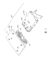
图4至图5是本实用新型未显示印刷电路板的电连接器组合的立体分解图。4 to 5 are three-dimensional exploded views of the electric connector assembly without the printed circuit board of the present invention.
图6至图7是图1示板端连接器沿A-A线和B-B线的剖视图。6 to 7 are cross-sectional views of the board connector shown in FIG. 1 along the lines A-A and B-B.
图8至图12是插头电连接器沿图1和图2中C-C线至G-G线方向的剖视图。8 to 12 are cross-sectional views of the electrical plug connector along the line C-C to line G-G in FIG. 1 and FIG. 2 .
图13是图1所示电连接器组合沿H-H线的剖视图。Fig. 13 is a cross-sectional view of the electrical connector assembly shown in Fig. 1 along line H-H.
【具体实施方式】 【Detailed ways】
请参照图1至图4,在本实施例中,本实用新型电连接器为电连接器组合300中的插头连接器100,该电连接器组合300还包括与插头连接器100配合的对接板端连接器200(第一对接连接器)。Please refer to FIG. 1 to FIG. 4 , in this embodiment, the electrical connector of the present invention is a
请参照图4至图5,插头连接器100包括第一本体2、组装至第一本体2的若干端子4、安装至第一本体2并为端子4的尾部提供支撑的隔板5、与端子4在隔板5上焊接的线缆(未图示),及将第一本体2、端子4与隔板5遮盖的导电壳体3。板端连接器200包括第二本体6、组装至第二本体6且与印刷电路板9焊接的若干端子7,及遮盖第二本体6和端子7的遮蔽壳体8。4 to 5, the
请参照图4至图5,并结合图8至图12,插头连接器100的第一本体2形成有上壁21、与上壁21相对设置的下壁22及连接上壁21与下壁22的一对侧壁23。侧壁23上设置有一对前端突然变细的导引柱230用以引导插头连接器100插入板端连接器200。每一导引柱230与上壁21的上表面共面,并且与下壁22的底面间隔一段距离。上壁21、下壁22与侧壁23共同围设形成一矩形收容空间20。Please refer to FIG. 4 to FIG. 5 , and in combination with FIG. 8 to FIG. 12 , the
上壁21设有若干自内表面向上凹进形成并与收容空间20连通的第一通道218,及自上表面向下凹进形成并与第一通道218相对设置的一对第二通道214。该对第二通道214分别部分凹入一对侧壁23,且不与收容空间20连通。上壁21上形成有一块长方形平台211,平台211比上壁21上表面高并超出上壁21的后边缘一段距离以形成一伸长部216。伸长部216开设有与第一通道218对齐排列的槽以形成若干个肋条2160。平台211的外侧边缘在横向方向(即端子4排列方向)与第二通道214相距一段距离。平台211的前端上表面向下凹进形成第一凹口210。一对第一凸块212设置于第一凹口210的相对的两侧。平台211中部设有一对与外侧相连通的第一槽2110。平台211的后方并邻近上壁21的后缘形成了第一突起217。上壁21的后部设有两对狭缝215,其中一对邻近平台211的后缘,另一对由第二通道214凹陷形成。下壁22设有与上壁21的第一凹口210和第一凸块212相对应的第二凹口220和第二凸块222。下壁22对应设有一对第二槽2210、一对第三槽2212及第二突起227。The
插头连接器100的端子4由若干第一端子41及位于第一端子41外侧用以传输电源的第二端子42组成。第一端子41由传输信号的两对差分对端子与位于每对差分对端子侧的三个接地端子组成。每一端子4包括弯曲的对接部40、尾部44及连接对接部40与尾部44的中间部43。每一中间部43设有一对第一倒刺45及与第一倒刺45间隔设置的第二倒刺46。第一端子41之间的间距相等,第二端子42与其邻近的第一端子41间的间距大于第一端子41间的间距。此外,第一端子41与第二端子42的对接部40弯曲的方向相反,也就是说,第一端子41的对接部40向下弯曲,而第二端子42向下弯曲。The
当组装至第一本体2时,第一、第二端子41、42分别插入第一、第二通道218、214,第一端子41的对接部40暴露于收容空间20,而第二端子42的对接部40暴露于第二通道214外并超出上壁21的上表面。中间部43的第一倒刺45与第一、第二通道218、214相干涉以固定端子4于第一本体2。尾部44延伸出第一本体2的后表面。此外,第二端子的工作电压为5伏。在其它实施例中,第二端子的工作电压也可以为其它值。When assembled to the
隔板5包括基部50、自基部50向后延伸的板部53及自基部50向前延伸的一对臂部52。若干第一通孔500贯穿基部50并与第一通道218呈直线排列,若干第二通孔502贯穿基部50并与第一本体的第二通道214呈直线排列。板部53的一面设有与第一、第二通孔500、502相连通的若干第一、第二通道531、532。每一臂部52包括面积较大并具有导引肋5210的第一臂部521及竖直方向上与第一臂部521对齐的第二臂部522。The
当隔板5组装于第一本体2时,臂部52的导引肋5210沿狭缝215滑动,第一本体2的后端夹置于隔板5的一对臂部52之间。第一、第二端子41、42的尾部44对应插入第一、第二通孔500、502,第二倒刺46与第一、第二通孔500、502干涉配合,以提高端子4与隔板5之间配合的稳定性。隔板5组装于第一本体2后,第一、第二端子41、42的尾部44位于隔板5的板部53的对应的第一、第二通道531、532。在板部53区域,线缆的导线(未图示)焊接于端子4。因而,隔板5具有整理并排列端子4的尾部44,以方便其后的焊接的功用。为提高隔板5与第一本体2之间结合的稳定性,隔板5设有若干槽道54以收容对应的肋条2160(请参照图12与图13)。When the
插头连接器100的导电壳体3包括第一壳体31及与第一壳体31啮合以共同屏蔽插头连接器100的第二壳体32。第一、第二壳体31、32包括U型的第一、第二前部310、320及较第一、第二前部310、320宽长的U型第一、第二后部312、322。第一、第二前部310、320设有与第一本体2的第一、第二槽2110、2210相对应的第一、第二切口311、321及从前面一部分裂开、收容于第一本体2的第一、第二凹口210、220并由第一、二凸块212、222定位的第一、第二弹性片313、323。第一前部310的一对竖直侧缘317分别遮盖平台211的侧缘,竖直侧缘317的后端插入狭缝215以保持第一壳体31于第一本体2。第二前部320的一对竖直侧缘327分别遮盖第一本体2的侧壁23。第一、第二后部312、322设有矩形第一、第二窗部318用以收容第一本体2的第一、第二突起217、227,以定位第一、第二壳体31、32于第一本体2。第一后部312的每一竖直侧缘314形成一对楔316,第二后部322的每一竖直侧缘324形成一对切口326用以收容楔316,以于第一、第二壳体31、32之间形成可靠接触。第二壳体32于第二后部322后端形成应力释放装置325用以紧抓线缆,以转移线缆所受应力。The
请参照图4、图5并结合图6与图7,板端连接器200的第二本体6包括主体部60、自主体部60向前延伸的舌部62及连接于主体部60的两侧并位于舌部62的相对两侧的一对侧部64。每一侧部64设有超越主体部60的前表面的第一U型部641、连接主体部60的中间部643及延伸出主体部60的后表面的第二L型部642。所述第一U型部641内侧形成板端连接器200的对接滑道,可方便插头连接器100的第二端子42插入。若干第一通道600贯穿主体部60,一对第二通道640贯穿侧部64的中间部643。舌部62设有若干具有不同长度的第一收容通道620。一对第二收容通道644设于侧部64的第一U型部641的上部。也就是说,第一、第二收容通道620、644于竖直方向被安排于不同的平面内。一对矩形凸块6420分别形成侧部64的第二L型部642的上表面。每一侧部64的外周设有一槽645。数个凸肋65自侧部64的中间部643的底缘向前延伸并与第一U型部641形成位于两者间的缺口650。Referring to FIG. 4 and FIG. 5 together with FIG. 6 and FIG. 7 , the
板端连接器200的端子7由若干第一端子71与一对第二端子72组成。第一端子71具有结构相同、用于传输信号的两对差分对端子及位于每对差分对端子两侧的三个接地端子。第二端子72位于第一端子71外侧,具相对第一端子71较大的尺寸并用以传输电源,并位于相对第一端子71较高的水平面内。每一端子7包括对接部70、自对接部70延伸的干涉部73及自干涉部73向下弯曲而后水平延伸的焊接部74以焊接于印刷电路板9。The terminals 7 of the
当端子7组装至第二本体6时,端子7插入第一、第二通道600、640,对接部70对应放置于第一、二收容通道620、644,干涉部73与第一、第二通道600、640相啮合以固定端子7于第二本体6。组装后,第一端子71的接地端子放置于较差分对端子靠前的舌部62处以提供可靠的信号传输。When the terminal 7 is assembled to the
板端连接器200的遮蔽壳体8呈U型,包括顶壁80、与顶壁80相对的底壁81及自顶壁80向下延伸的一对侧壁82。顶壁80设有一对第一弹性指800与用以收容凸块6420以定位遮蔽壳体8于第二本体6。底壁81对应第一弹性指800处设有一对第二弹性指810,底壁81的后缘插入第二本体6的缺口650。每一侧壁82形成一压片820用以锁入侧部64的槽645内以固定遮蔽壳体8。每一侧壁82设有固持脚822以定位遮蔽壳体8于印刷电路板9。若干弹片83由顶壁80、底壁81及侧壁82的前边缘竖直向外弯折形成,每一弹片83形成有隆起830以在板端连接器200安装于面板时增加弹片83抵压面板的弹性力。The shielding
请参照图1至图3并结合图13,当插头连接器100与板端连接器200配接时,插头连接器100的导引柱230沿板端连接器200的侧部64的第一U型部641滑动以导引插头连接器100进入板端连接器200。插头连接器100的收容空间20会收容板端连接器200,板端连接器200的第一端子71的对接部70与暴露于收容空间的插头连接器100的第一端子41的弯曲状对接部40相配接,板端连接器200的第二端子72的对接部70与延伸出上壁21的上表面的插头连接器100的第二端子42的弯曲状对接部40相配接。第一和第二前部310、320会对应插入遮蔽体8的顶壁80和底壁81与舌部62之间形成的空间内,第一和第二弹性指800、810压入第一与第二切口311、321及第一本体2的第一与第二槽2110、2210。同时,第一与第二弹性片313、323抵压顶壁80和底壁81的内表面以增加导电壳体3与遮蔽壳体8之间的固持力。1 to 3 in combination with FIG. 13 , when the
当插头连接器100与另一板端连接器(未图示,第二对接连接器),该板端连接器具有与板端连接器200相同的尺寸却不具有第二端子72,配接时,插头连接器100的第二端子42会闲置(即不与任何元件电性配接)。亦即,插头连接器100可以兼容两种不同的板端连接器。When the
当然,板端连接器200亦可兼容具相同尺寸带有第二端子或不具第二端子两种不同的插头连接器。Of course, the
Claims (10)
Applications Claiming Priority (2)
| Application Number | Priority Date | Filing Date | Title |
|---|---|---|---|
| US11/633,815 US7255607B1 (en) | 2006-12-05 | 2006-12-05 | Compatible electrical connector |
| US11/633815 | 2006-12-05 |
Publications (1)
| Publication Number | Publication Date |
|---|---|
| CN201113096Y true CN201113096Y (en) | 2008-09-10 |
Family
ID=38336982
Family Applications (2)
| Application Number | Title | Priority Date | Filing Date |
|---|---|---|---|
| CNU200720183072XU Expired - Fee Related CN201113096Y (en) | 2006-12-05 | 2007-10-23 | electrical connector |
| CNA200710166619XA Pending CN101197483A (en) | 2006-12-05 | 2007-10-23 | electrical connector |
Family Applications After (1)
| Application Number | Title | Priority Date | Filing Date |
|---|---|---|---|
| CNA200710166619XA Pending CN101197483A (en) | 2006-12-05 | 2007-10-23 | electrical connector |
Country Status (3)
| Country | Link |
|---|---|
| US (2) | US7255607B1 (en) |
| CN (2) | CN201113096Y (en) |
| TW (1) | TWM335045U (en) |
Cited By (2)
| Publication number | Priority date | Publication date | Assignee | Title |
|---|---|---|---|---|
| CN107134692A (en) * | 2016-12-15 | 2017-09-05 | 番禺得意精密电子工业有限公司 | Electric connector |
| CN109411958A (en) * | 2018-06-05 | 2019-03-01 | 温州意华接插件股份有限公司 | High speed interconnecting assembly |
Families Citing this family (36)
| Publication number | Priority date | Publication date | Assignee | Title |
|---|---|---|---|---|
| US7255607B1 (en) * | 2006-12-05 | 2007-08-14 | Hon Hai Precision Ind. Co., Ltd. | Compatible electrical connector |
| CN201018053Y (en) * | 2007-01-22 | 2008-02-06 | 富士康(昆山)电脑接插件有限公司 | Electric connector assembly |
| US7708600B2 (en) * | 2007-08-14 | 2010-05-04 | Hon Hai Precision Ind. Co., Ltd. | Compatible electrical connector |
| US20090186529A1 (en) * | 2007-09-04 | 2009-07-23 | Taiwin Electronics Co., Ltd | Powered external serial advanced technology attachment plug |
| US20090061665A1 (en) * | 2007-09-04 | 2009-03-05 | Taiwan Electronics Co., Ltd. | Powered external serial advancement technology attachment socket |
| CN201130767Y (en) * | 2007-10-12 | 2008-10-08 | 富士康(昆山)电脑接插件有限公司 | electrical connector |
| US8137127B2 (en) * | 2007-12-13 | 2012-03-20 | Ati Technologies Ulc | Electronic devices using divided multi-connector element differential bus connector |
| US7850490B2 (en) * | 2007-12-13 | 2010-12-14 | Ati Technologies Ulc | Electrical connector, cable and apparatus utilizing same |
| US7861013B2 (en) * | 2007-12-13 | 2010-12-28 | Ati Technologies Ulc | Display system with frame reuse using divided multi-connector element differential bus connector |
| US7963809B2 (en) * | 2008-01-06 | 2011-06-21 | Apple Inc. | Microdvi connector |
| US20090181578A1 (en) * | 2008-01-13 | 2009-07-16 | T-Conn Precision Corp. | Connector assembly |
| CN101499568B (en) * | 2008-02-01 | 2013-03-13 | 富士康(昆山)电脑接插件有限公司 | Cable connector assembly and method of making same |
| US7611386B1 (en) | 2008-06-12 | 2009-11-03 | Hon Hai Precision Ind. Co., Ltd | Electrical connector with power contacts designed to handle instantaneous inrush current |
| US7611387B1 (en) | 2008-06-12 | 2009-11-03 | Hon Hai Precision Ind. Co., Ltd. | Electrical connector provided with power terminals adapted to carry different voltages |
| TWM350153U (en) * | 2008-08-22 | 2009-02-01 | Taiwin Electronics Co Ltd | |
| WO2010046735A1 (en) * | 2008-10-22 | 2010-04-29 | Fci | Shielded connector |
| TW201021328A (en) | 2008-11-21 | 2010-06-01 | Apacer Technology Inc | SATA connector capable of directly transmitting power supply |
| JP4887393B2 (en) * | 2009-03-24 | 2012-02-29 | ホシデン株式会社 | connector |
| US8070526B2 (en) * | 2009-08-19 | 2011-12-06 | Hon Hai Precision Ind. Co., Ltd. | Electrical connector with improved terminals assembled to insulative housing from top to bottom |
| CN201708323U (en) * | 2010-04-19 | 2011-01-12 | 富士康(昆山)电脑接插件有限公司 | Cable connector assembly |
| US20120071027A1 (en) * | 2010-09-21 | 2012-03-22 | Cheng Uei Precision Industry Co., Ltd. | Electrical connector |
| US8753150B2 (en) * | 2011-06-23 | 2014-06-17 | Apple Inc. | Simplified connector receptacles |
| KR20130059111A (en) * | 2011-11-28 | 2013-06-05 | 타이코에이엠피(유) | Connecting plug for portable terminal |
| US8684769B2 (en) * | 2012-05-24 | 2014-04-01 | Hon Hai Precision Industry Co., Ltd. | Electrical connector having terminal portions in specific arrangement and a grounding plate for excellent high-frequency characteristics |
| CN203288840U (en) * | 2012-12-27 | 2013-11-13 | 富士康(昆山)电脑接插件有限公司 | Cable connector assembly |
| JP6039494B2 (en) * | 2013-04-25 | 2016-12-07 | 日本航空電子工業株式会社 | Electrical connector |
| TWI556525B (en) * | 2014-07-14 | 2016-11-01 | Advanced Connectek Inc | Electrical connector plug |
| CN105490089B (en) * | 2014-09-15 | 2018-01-05 | 富士康(昆山)电脑接插件有限公司 | Electric connector combination |
| CN204464650U (en) * | 2015-02-11 | 2015-07-08 | 富士康(昆山)电脑接插件有限公司 | Cable Connector Assembly |
| US9728898B1 (en) * | 2016-02-01 | 2017-08-08 | Microsoft Technology Licensing, Llc | Conductive shell for a cable assembly |
| CN109546424B (en) * | 2017-09-22 | 2021-04-09 | 上海莫仕连接器有限公司 | Electric connector assembly and electric connector |
| TWI642237B (en) * | 2017-10-06 | 2018-11-21 | 唐虞企業股份有限公司 | Electrical connector assembly and its board end connector and cable end connector |
| CN109921213B (en) * | 2017-12-13 | 2021-06-22 | 唐虞企业股份有限公司 | Electric connector assembly and plate end connector and wire end connector thereof |
| TWM607153U (en) * | 2020-09-16 | 2021-02-01 | 宏碁股份有限公司 | Plug electrical connector and receptacle electrical connector |
| DE102020133318B4 (en) * | 2020-12-14 | 2022-11-10 | Lear Corporation | Electrical data link device |
| CN214754366U (en) * | 2021-06-18 | 2021-11-16 | 立讯精密工业股份有限公司 | Metal shell and connector |
Family Cites Families (9)
| Publication number | Priority date | Publication date | Assignee | Title |
|---|---|---|---|---|
| US4867690A (en) * | 1988-06-17 | 1989-09-19 | Amp Incorporated | Electrical connector system |
| US5356300A (en) * | 1993-09-16 | 1994-10-18 | The Whitaker Corporation | Blind mating guides with ground contacts |
| US5697799A (en) * | 1996-07-31 | 1997-12-16 | The Whitaker Corporation | Board-mountable shielded electrical connector |
| TWM244615U (en) | 2003-10-15 | 2004-09-21 | Comax Technology Inc | External high-frequency connector |
| US6832934B1 (en) * | 2004-03-18 | 2004-12-21 | Hon Hai Precision Ind. Co., Ltd | High speed electrical connector |
| US6910914B1 (en) | 2004-08-11 | 2005-06-28 | Hon Hai Precision Ind. Co., Ltd. | Shielded cable end connector assembly |
| US7097507B1 (en) | 2005-06-02 | 2006-08-29 | Hon Hai Precision Ind. Co., Ltd. | Electrical connector with improved shell |
| US7247058B2 (en) * | 2005-08-25 | 2007-07-24 | Tyco Electronics Corporation | Vertical docking connector |
| US7255607B1 (en) * | 2006-12-05 | 2007-08-14 | Hon Hai Precision Ind. Co., Ltd. | Compatible electrical connector |
-
2006
- 2006-12-05 US US11/633,815 patent/US7255607B1/en not_active Expired - Fee Related
-
2007
- 2007-08-14 US US11/893,074 patent/US7402084B2/en not_active Expired - Fee Related
- 2007-10-08 TW TW096216777U patent/TWM335045U/en unknown
- 2007-10-23 CN CNU200720183072XU patent/CN201113096Y/en not_active Expired - Fee Related
- 2007-10-23 CN CNA200710166619XA patent/CN101197483A/en active Pending
Cited By (3)
| Publication number | Priority date | Publication date | Assignee | Title |
|---|---|---|---|---|
| CN107134692A (en) * | 2016-12-15 | 2017-09-05 | 番禺得意精密电子工业有限公司 | Electric connector |
| CN109411958A (en) * | 2018-06-05 | 2019-03-01 | 温州意华接插件股份有限公司 | High speed interconnecting assembly |
| CN109411958B (en) * | 2018-06-05 | 2023-11-14 | 温州意华接插件股份有限公司 | high speed interconnect components |
Also Published As
| Publication number | Publication date |
|---|---|
| TWM335045U (en) | 2008-06-21 |
| US7402084B2 (en) | 2008-07-22 |
| CN101197483A (en) | 2008-06-11 |
| US20080132116A1 (en) | 2008-06-05 |
| US7255607B1 (en) | 2007-08-14 |
Similar Documents
| Publication | Publication Date | Title |
|---|---|---|
| CN201113096Y (en) | electrical connector | |
| US7708600B2 (en) | Compatible electrical connector | |
| CN102420366B (en) | Electrical connectors and combination therefrom | |
| CN101640333B (en) | Connector | |
| CN201252288Y (en) | Electrical connector | |
| US8834185B2 (en) | Electrical connector assembly with compact configuration | |
| CN201229997Y (en) | Combination of electric connector | |
| CN201054403Y (en) | Cable connector | |
| CN2665975Y (en) | Electric connector | |
| CN102790314B (en) | Cable connector assembly | |
| US8011961B2 (en) | Cable assembly with grounding pieces | |
| CN201355711Y (en) | electrical connector | |
| CN2699530Y (en) | Electric connector | |
| US20100291801A1 (en) | Electrical connector with improved contacts | |
| CN102931522B (en) | Cable connector component | |
| CN106252992A (en) | First adapter of docking and the second adapter | |
| CN103166022A (en) | electrical connector | |
| CN101667695A (en) | Connector device having shielding function | |
| US20100151743A1 (en) | Electrical adapter | |
| CN101609945A (en) | Electric connector | |
| CN102324656A (en) | Electrical connectors and combinations thereof | |
| CN2850038Y (en) | Electric connector assembly | |
| US6863546B2 (en) | Cable connector assembly having positioning structure | |
| CN103972730A (en) | Electrical connector | |
| CN100466392C (en) | Electrical Connector Assembly |
Legal Events
| Date | Code | Title | Description |
|---|---|---|---|
| C14 | Grant of patent or utility model | ||
| GR01 | Patent grant | ||
| C17 | Cessation of patent right | ||
| CF01 | Termination of patent right due to non-payment of annual fee |
Granted publication date: 20080910 Termination date: 20121023 |