CN1993913A - Peak power suppressing apparatus and peak power suppressing method - Google Patents
Peak power suppressing apparatus and peak power suppressing method Download PDFInfo
- Publication number
- CN1993913A CN1993913A CNA2005800266451A CN200580026645A CN1993913A CN 1993913 A CN1993913 A CN 1993913A CN A2005800266451 A CNA2005800266451 A CN A2005800266451A CN 200580026645 A CN200580026645 A CN 200580026645A CN 1993913 A CN1993913 A CN 1993913A
- Authority
- CN
- China
- Prior art keywords
- signal
- power
- distortion component
- unit
- peak power
- Prior art date
- Legal status (The legal status is an assumption and is not a legal conclusion. Google has not performed a legal analysis and makes no representation as to the accuracy of the status listed.)
- Pending
Links
Images


Classifications
-
- H—ELECTRICITY
- H04—ELECTRIC COMMUNICATION TECHNIQUE
- H04B—TRANSMISSION
- H04B1/00—Details of transmission systems, not covered by a single one of groups H04B3/00 - H04B13/00; Details of transmission systems not characterised by the medium used for transmission
- H04B1/02—Transmitters
- H04B1/04—Circuits
- H04B1/0475—Circuits with means for limiting noise, interference or distortion
-
- H—ELECTRICITY
- H04—ELECTRIC COMMUNICATION TECHNIQUE
- H04L—TRANSMISSION OF DIGITAL INFORMATION, e.g. TELEGRAPHIC COMMUNICATION
- H04L27/00—Modulated-carrier systems
- H04L27/26—Systems using multi-frequency codes
- H04L27/2601—Multicarrier modulation systems
- H04L27/2614—Peak power aspects
- H04L27/2623—Reduction thereof by clipping
-
- H—ELECTRICITY
- H03—ELECTRONIC CIRCUITRY
- H03G—CONTROL OF AMPLIFICATION
- H03G11/00—Limiting amplitude; Limiting rate of change of amplitude
-
- H—ELECTRICITY
- H04—ELECTRIC COMMUNICATION TECHNIQUE
- H04B—TRANSMISSION
- H04B2201/00—Indexing scheme relating to details of transmission systems not covered by a single group of H04B3/00 - H04B13/00
- H04B2201/69—Orthogonal indexing scheme relating to spread spectrum techniques in general
- H04B2201/707—Orthogonal indexing scheme relating to spread spectrum techniques in general relating to direct sequence modulation
- H04B2201/70706—Orthogonal indexing scheme relating to spread spectrum techniques in general relating to direct sequence modulation with means for reducing the peak-to-average power ratio
Landscapes
- Engineering & Computer Science (AREA)
- Computer Networks & Wireless Communication (AREA)
- Signal Processing (AREA)
- Transmitters (AREA)
- Tone Control, Compression And Expansion, Limiting Amplitude (AREA)
- Geophysics And Detection Of Objects (AREA)
Abstract
提供峰值功率抑制装置,它能够提高接收端装置的接收差错率特性。在该装置中,消波单元(102)通过对所输入的信号进行消波处理而抑制信号的峰值功率。减法电路(104)提取峰值功率被抑制的信号中的频带内失真分量。减法电路(111)通过从峰值功率被抑制的信号中减去所提取出的频带内失真分量,从而除去在峰值功率被抑制的信号的频带内残留的失真分量。
A peak power suppression device is provided, which improves the reception error rate characteristics of the receiving device. In this device, the cancellation unit (102) suppresses the peak power of the signal by performing cancellation processing on the input signal. The subtraction circuit (104) extracts the in-band distortion component from the signal with suppressed peak power. The subtraction circuit (111) removes the residual distortion component in the frequency band of the signal with suppressed peak power by subtracting the extracted in-band distortion component from the signal with suppressed peak power.
Description
技术领域technical field
本发明涉及峰值功率抑制装置和峰值功率抑制方法,特别涉及在OFDM(Orthogonal Frequency Division Multiplex:正交频分复用)方式的无线发送装置中所使用的峰值功率抑制装置和峰值功率抑制方法。The present invention relates to a peak power suppressing device and a peak power suppressing method, in particular to a peak power suppressing device and a peak power suppressing method used in an OFDM (Orthogonal Frequency Division Multiplex: Orthogonal Frequency Division Multiplex) wireless transmission device.
背景技术Background technique
近年来,在移动通信中,对高速大容量通信的需求日益增高,因此,例如OFDM方式作为实现它的调制方式备受瞩目。在OFDM方式中,使用在频率轴上正交配置多个副载波的多载波信号。多载波信号是通过合成多个载波而获得的,因此有时出现较高的峰值功率。作为表示峰值功率的大小的指标,例如使用PAPR(Peak to Average Power Ratio:峰均功率比)值,在OFDM方式中,副载波数越多PAPR值也越大。In recent years, in mobile communication, the demand for high-speed and large-capacity communication has been increasing, and therefore, for example, the OFDM method has attracted attention as a modulation method for realizing it. In the OFDM scheme, a multicarrier signal in which a plurality of subcarriers are arranged orthogonally on the frequency axis is used. A multi-carrier signal is obtained by combining multiple carriers and therefore sometimes has higher peak power. As an index indicating the magnitude of the peak power, for example, PAPR (Peak to Average Power Ratio: peak-to-average power ratio) value is used. In the OFDM method, the greater the number of subcarriers, the greater the PAPR value.
以往的抑制峰值功率的方式例如有专利文献1所记载的所谓消波滤波(Clipping and Filtering)法。参照附图说明消波滤波法的动作。图1是表示以往的实现消波滤波法的峰值功率抑制装置的结构的一个例子的方框图。如图2所示,在发送信号的振幅值为大于事先设定的阈值时,该振幅值因消波单元11的消波处理而被限制。从频率轴上看该处理时,如图3B所示,对具有图3A所示的频谱的发送信号进行消波处理时,在发送信号的频带内和频带外出现失真分量。由滤波单元12除去有可能对相邻信道造成干扰的频带外失真分量,而获得具有如图3C所示的频谱的发送信号。A conventional method for suppressing peak power includes, for example, the so-called clipping and filtering method described in Patent Document 1. The operation of the clipping filter method will be described with reference to the drawings. FIG. 1 is a block diagram showing an example of the configuration of a conventional peak power suppressing device for realizing a clipping filter method. As shown in FIG. 2 , when the amplitude value of the transmission signal is greater than a preset threshold value, the amplitude value is limited by the clipping processing of the clipping unit 11 . When this processing is viewed on the frequency axis, as shown in FIG. 3B , when clipping processing is performed on a transmission signal having the frequency spectrum shown in FIG. 3A , distortion components appear within and outside the frequency band of the transmission signal. The out-of-band distortion components that may interfere with adjacent channels are removed by the filtering unit 12 to obtain a transmission signal having a frequency spectrum as shown in FIG. 3C.
[专利文献1]特开2002-185432号公报[Patent Document 1] JP-A-2002-185432
发明内容Contents of the invention
本发明需要解决的问题The problem that the present invention needs to solve
然而,在上述以往的峰值功率抑制装置中,虽然能够由滤波处理除去发送信号的频带外失真,但无法通过滤波处理除去发送信号的频带内失真,所以频带内失真依然残留在发送信号中。因此有如下问题,即,向通信对方装置发送在频带内残留着失真分量的信号时,使通信对方装置的接收差错率特性恶化。However, in the conventional peak power suppression device described above, although out-of-band distortion of the transmission signal can be removed by filtering, in-band distortion of the transmission signal cannot be removed by filtering, so in-band distortion still remains in the transmission signal. Therefore, there is a problem that, when a signal in which a distortion component remains in a frequency band is transmitted to a communication partner device, the reception error rate characteristic of the communication partner device deteriorates.
本发明的目的为提供一种峰值功率抑制装置和峰值功率抑制方法,它能够提高接收端装置的接收差错率特性。An object of the present invention is to provide a peak power suppressing device and a peak power suppressing method capable of improving the reception error rate characteristic of a receiving end device.
解决问题的方案solution to the problem
本发明的峰值功率抑制装置所采用的结构包括:抑制单元,抑制信号的峰值功率;提取单元,提取峰值功率被抑制的信号中的频带内失真分量;以及除去单元,从峰值功率被抑制的信号中,除去所提取出的频带内失真分量。The structure adopted by the peak power suppression device of the present invention includes: a suppression unit, which suppresses the peak power of the signal; an extraction unit, which extracts the in-band distortion component in the signal whose peak power is suppressed; and a removal unit, which extracts the signal from the peak power suppressed signal , remove the extracted in-band distortion components.
本发明的峰值功率抑制方法包括:抑制步骤,抑制信号的峰值功率;提取步骤,提取峰值功率被抑制的信号中的频带内失真分量;以及除去步骤,从峰值功率被抑制的信号中,除去所提取出的频带内失真分量。The peak power suppressing method of the present invention includes: a suppressing step, suppressing the peak power of the signal; an extracting step, extracting the in-band distortion component in the signal whose peak power is suppressed; and a removing step, removing all The extracted in-band distortion components.
发明的效果The effect of the invention
根据本发明,能够提高接收端装置的接收差错率特性。According to the present invention, it is possible to improve the reception error rate characteristic of the receiving end device.
附图说明Description of drawings
图1是表示以往的峰值功率抑制装置的结构的一个例子的方框图。FIG. 1 is a block diagram showing an example of the configuration of a conventional peak power suppression device.
图2是表示发送信号的振幅值的例子的图。FIG. 2 is a diagram showing an example of an amplitude value of a transmission signal.
图3是表示以往的峰值功率抑制装置的发送信号的频谱的图。FIG. 3 is a diagram showing a frequency spectrum of a transmission signal of a conventional peak power suppressing device.
图4是表示本发明实施方式1的无线发送装置的结构的方框图。Fig. 4 is a block diagram showing the configuration of a wireless transmission device according to Embodiment 1 of the present invention.
图5是表示本发明实施方式1的发送信号的频谱的图。FIG. 5 is a diagram showing a frequency spectrum of a transmission signal according to Embodiment 1 of the present invention.
图6是表示本发明实施方式2的无线发送装置的结构的方框图。Fig. 6 is a block diagram showing the configuration of a wireless transmission device according to Embodiment 2 of the present invention.
图7是表示本发明实施方式3的无线发送装置的结构的方框图。Fig. 7 is a block diagram showing the configuration of a radio transmission device according to Embodiment 3 of the present invention.
图8是表示本发明实施方式3的无线发送装置的动作的流程图。Fig. 8 is a flowchart showing the operation of the wireless transmission device according to Embodiment 3 of the present invention.
具体实施方式Detailed ways
下面,使用附图详细地说明本发明的实施方式。Hereinafter, embodiments of the present invention will be described in detail using the drawings.
(实施方式1)(Embodiment 1)
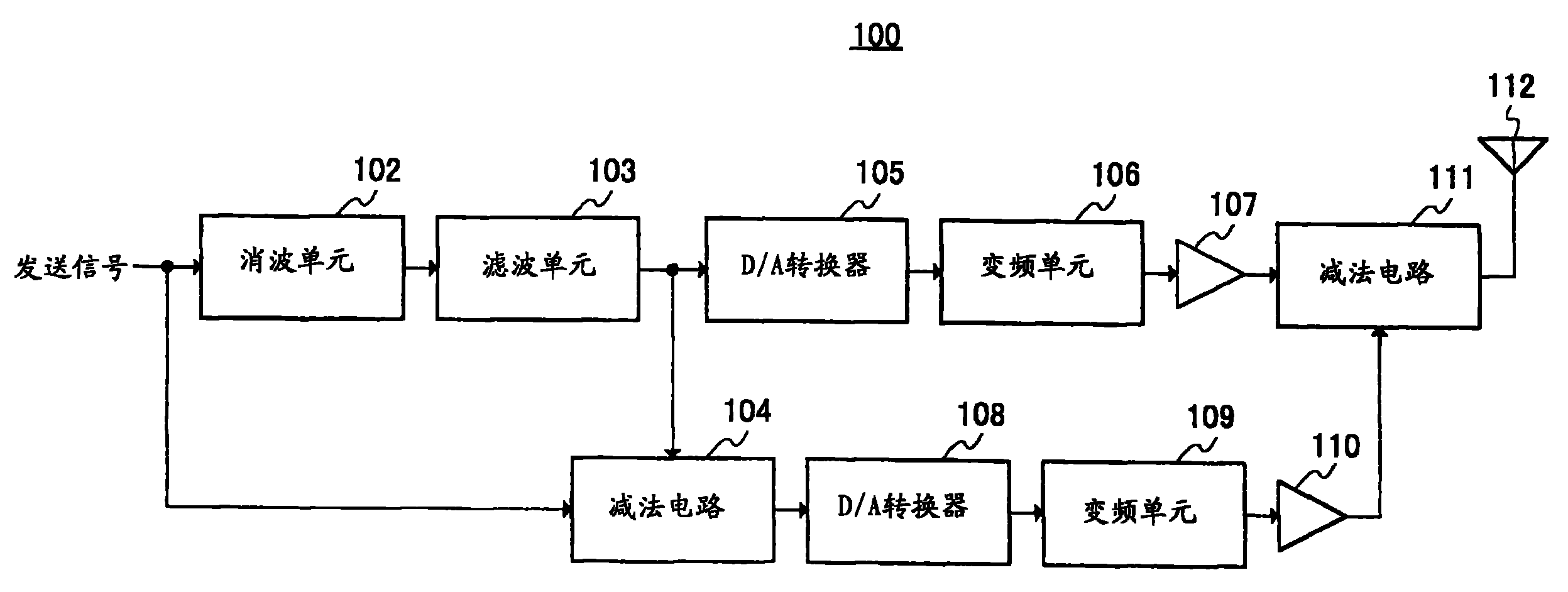
图4是表示本发明实施方式1的适用峰值功率抑制装置的无线发送装置的结构的方框图。4 is a block diagram showing the configuration of a wireless transmission device to which the peak power suppressing device according to Embodiment 1 of the present invention is applied.
图4的无线发送装置100包括:消波单元102、滤波单元103、减法电路104、D/A转换器105、变频单元106、功率放大器107、D/A转换器108、变频单元109、功率放大器110、减法电路111以及天线112。The
在消波单元102,作为抑制手段,对发送信号中的阈值以上的振幅分量进行消波处理。由此抑制发送信号的峰值功率。在滤波单元103,对消波单元102的输出信号进行滤波处理,以除去发送信号中的频带外失真分量。在D/A转换器105将滤波单元103的输出信号从数字信号转换到模拟信号。在变频单元106对D/A转换器105的输出信号进行频率变换,从基带信号变换到RF(Radio Frequency)频带信号。在功率放大器107,作为属于主发送系统的第一放大单元,对变频单元106的输出信号进行放大处理。在减法电路104,作为提取单元,从滤波单元103的输出信号减去原本的发送信号,即进行消波处理之前的发送信号,以提取发送信号的频带内失真分量。在D/A转换器108,将减法电路104的输出信号即频带内失真分量,从数字信号转换到模拟信号。在变频单元109,对从D/A转换器108输出的信号进行频率变换,从基带信号变换到RF频带信号。在功率放大器110,作为属于副发送系统的第二放大单元,对变频单元109的输出信号进行放大处理。在减法电路111,作为除去单元,从功率放大器107的输出信号减去功率放大器110的输出信号,由此从发送信号除去频带内失真分量。将已除去频带内失真分量的发送信号从天线112无线发送出去。In the
接着,使用图5A~图5E说明包括上述结构的无线发送装置100的动作。Next, the operation of
被输入到消波单元102的发送信号具有例如图5A所示的频谱。因而发送信号在消波单元102被施以消波处理。通过该处理,规定的阈值以上的振幅分量受到限制,从而抑制峰值功率。这里,基于设计上决定的PAPR值而决定上述阈值。例如,PAPR值为6dB时,将比平均信号功率高6dB的值设定为阈值。由此,如图5B所示,就被消波的发送信号而言,在频带内和频带外分别包含失真分量。The transmission signal input to clipping
被消波的发送信号在滤波单元103受到滤波处理。如图5C所示,通过该处理只除去了频带外失真分量。在此时,发送信号中还残留着频带内失真分量。The clipped transmission signal is subjected to filtering processing in
对从滤波单元103输出的发送信号,在D/A转换器105和变频单元106分别进行D/A转换处理和频率变换处理,然后在功率放大器107进行放大。The transmission signal output from
另一方面,在减法电路104中,从滤波单元103的输出信号中减去原本的发送信号。其结果,如图5D所示,提取了发送信号中的频带内失真分量。将所提取出的频带内失真分量在功率放大器110放大。另外,副发送系统中的功率放大器110仅用于放大频带内失真分量,因此与主发送系统的功率放大器107相比,输出特性较小的放大器就可以。On the other hand, in
然后,在减法电路111,从作为功率放大器107的输出信号的发送信号减去作为功率放大器110的输出信号的频带内失真分量。由此,从发送信号除去了频带内失真分量。其结果,所获得的发送信号具有例如图5E所示的频谱。Then, in the
这样,根据本实施方式,由于从被抑制峰值功率的发送信号中除去频带内失真分量,因此能够提高接收端装置的接收差错率特性。As described above, according to the present embodiment, since the in-band distortion component is removed from the transmission signal whose peak power is suppressed, it is possible to improve the reception error rate characteristic of the receiving side apparatus.
另外,根据本实施方式,因为从经放大的发送信号中除去频带内失真分量,所以有时因频带内失真分量的除去,在时间轴上重新出现峰值功率而使得PAPR值增大。但是,PAPR值在功率放大器107的输入级被抑制为设定值以下即可。因此,即使PAPR值在功率放大器107的后级增大,也能够防止对功率放大器107的补偿设定造成影响,该补偿设定是指为了保持功率放大器107的线性而设定表示最大振幅电平和饱和电平的差的补偿值。Also, according to the present embodiment, since the in-band distortion component is removed from the amplified transmission signal, the removal of the in-band distortion component may cause the peak power to reappear on the time axis and increase the PAPR value. However, it is sufficient that the PAPR value is suppressed below a set value at the input stage of the
(实施方式2)(Embodiment 2)
图6是表示本发明实施方式2的适用峰值功率抑制装置的无线发送装置的结构的方框图。另外,图6的无线发送装置200与在实施方式1说明的无线发送装置100具有相同的基本结构,因此对相同的结构元素赋予相同的参照标号,并省略其详细说明。6 is a block diagram showing the configuration of a wireless transmission device to which a peak power suppressing device according to Embodiment 2 of the present invention is applied. Note that radio transmission device 200 in FIG. 6 has the same basic configuration as
无线发送装置200包括:D/A转换器201、变频单元202、减法电路203以及功率放大器204,以代替在实施方式1说明的减法电路104、D/A转换器108、变频单元109以及功率放大器110,还添加有衰减电路205。The radio transmission device 200 includes a D/A converter 201, a frequency conversion unit 202, a subtraction circuit 203, and a power amplifier 204, instead of the
在D/A转换器201,原本的发送信号被从数字信号转换到模拟信号。在变频单元202,将D/A转换器201的输出信号从基带信号变换到RF频带信号。In the D/A converter 201, the original transmission signal is converted from a digital signal to an analog signal. In the frequency conversion unit 202, the output signal of the D/A converter 201 is converted from a baseband signal to an RF band signal.
在衰减电路205,使功率放大器107的输出信号衰减。在作为提取单元的减法电路203,,从功率放大器107的输出信号减去变频单元202的输出信号,从而提取出发送信号中的频带内失真分量。这时,也提取出功率放大器107的非线性失真分量。在功率放大器204,作为属于副发送系统的第二放大单元,放大减法电路203的输出信号。In the attenuation circuit 205, the output signal of the
也就是说,在实施方式1在基带进行频带内失真分量的提取处理,相对于此,在本实施方式,在RF频带进行该处理。That is, whereas in Embodiment 1, the extraction processing of in-band distortion components is performed in the baseband, in this embodiment, this processing is performed in the RF band.
接着,说明具有上述结构的无线发送装置200的动作。Next, the operation of radio transmission device 200 having the above configuration will be described.
在衰减电路205,使功率放大器107的输出信号衰减。从衰减的信号中,减去分别在D/A转换器201和变频单元202进行了D/A转换处理和频率变换处理的发送信号。其结果,提取出发送信号的频带内失真分量。并且,这时也提取出在主发送系统的功率放大器107所发生的非线性失真。In the attenuation circuit 205, the output signal of the
在功率放大器204中,将所提取的频带内失真分量和非线性失真分量放大。副发送系统中的功率放大器204仅用于放大对频带内失真分量和非线性失真分量,因此与主发送系统的功率放大器107相比,输出特性较小的放大器就可以。In the power amplifier 204, the extracted in-band distortion components and nonlinear distortion components are amplified. The power amplifier 204 in the sub-transmission system is only used to amplify in-band distortion components and nonlinear distortion components, so an amplifier with smaller output characteristics than the
然后在减法电路111,从作为功率放大器107的输出信号的发送信号,减去作为功率放大器204的输出信号的频带内失真分量和非线性失真分量。由此,从发送信号除了频带内失真分量之外还除去了非线性失真分量。Then, in the
这样,根据本实施方式,由于提取放大的发送信号的频带内失真分量,因此不仅能够提取因峰值功率的抑制而发生的频带内失真分量,还能够提取因功率放大器107的放大而发生的非线性失真分量,并且能够除去提取出的两种失真分量,从而能够进一步提高接收端装置的接收差错率特性。Thus, according to the present embodiment, since the in-band distortion components of the amplified transmission signal are extracted, not only the in-band distortion components generated by suppression of the peak power but also the nonlinear components generated by the amplification of the
(实施方式3)(Embodiment 3)
图7是表示本发明实施方式3的无线发送装置的结构的方框图。另外,图7的无线发送装置300与在实施方式1说明的无线发送装置100具有相同的基本结构,因此对相同的结构元素赋予相同的参照标号,并省略其详细说明。Fig. 7 is a block diagram showing the configuration of a radio transmission device according to Embodiment 3 of the present invention. Note that radio transmission device 300 in FIG. 7 has the same basic configuration as
无线发送装置300除了无线发送装置100的结构之外,还包括功率计算单元301、判定单元302以及电源控制单元303。Wireless transmission device 300 includes power calculation unit 301 , determination unit 302 , and power control unit 303 in addition to the configuration of
在作为测定单元的功率计算单元301,,测定频带内失真分量的功率。在判定单元302判定测定出的功率是否超过阈值。In the power calculation unit 301' as a measurement unit, the power of the in-band distortion component is measured. Judging section 302 judges whether or not the measured power exceeds a threshold value.
在作为控制单元的电源控制单元303,,功率放大器110的电源基于判定单元302的判定结果而被控制。更具体地说,基于因消波而发生的频带内失真分量的功率量,进行或停止副发送系统的功率放大器110的动作。在频带内失真分量的功率量大于以满足规定的差错率的方式而设定的阈值时,使功率放大器110进行放大动作,小于阈值则使其停止放大动作。In a power supply control unit 303′ as a control unit, the power supply of the
接着,使用图8说明包括上述结构的无线发送装置300的动作。Next, the operation of radio transmission device 300 including the above configuration will be described with reference to FIG. 8 .
首先,将原本的发送信号和滤波单元103的输出信号输入到减法电路104,并提取频带内失真分量(步骤S501)。然后,将从减法电路104输出的频带内失真分量输入到功率计算单元301。在功率计算单元301计算频带内失真分量的功率量(步骤S502)。功率量的计算方法例如有对1OFDM码元时间的失真分量信号进行积分的方法。First, the original transmission signal and the output signal of the
从功率计算单元301输出的功率量被输入到判定单元302。在判定单元302判定功率量是否大于阈值(步骤S503)。这里,例如基于事先由仿真测试获得的失真分量功率量对差错率特性而设定该阈值以使差错率为一定的水平以下。判定单元302的判定结果被输入到电源控制电源303。在功率量大于阈值时(S503:“是”),电源控制单元303接通功率放大器110的电源,以使功率放大器110执行放大动作(步骤S504)。相反地,在功率量为阈值以下时(S503:“否”),电源控制单元303关断功率放大器110的电源,以使功率放大器110停止放大动作(步骤S505)。通过该操作,在能够保持提高接收端装置的接收差错率特性的效果的同时,与常时动作功率放大器110的情况相比能够削减无线发送装置300的消耗功率。The power amount output from the power calculation unit 301 is input to the determination unit 302 . It is determined at the determination unit 302 whether the power amount is greater than a threshold (step S503). Here, the threshold is set so that the error rate is equal to or lower than a certain level based on, for example, the distortion component power versus error rate characteristic obtained in advance by a simulation test. The determination result of the determination unit 302 is input to the power control power supply 303 . When the power amount is greater than the threshold (S503: "Yes"), the power control unit 303 turns on the power of the
另外,用于上述各实施方式的说明中的各功能块通常可实现为LSI,它是一种集成电路。这些块既可是每个块分别集成到一个芯片,或者可以是一部分或所有块集成到一个芯片。In addition, each functional block used in the description of each of the above-mentioned embodiments can generally be realized as an LSI, which is a type of integrated circuit. Each of these blocks may be individually integrated into one chip, or a part or all of the blocks may be integrated into one chip.
虽然此处称为LSI,但根据集成程度,可以被称为IC、系统LSI、超级LSI(Super LSI)、或特大LSI(Ultra LSI)。Although it is called LSI here, it may be called IC, system LSI, super LSI (Super LSI), or super LSI (Ultra LSI) depending on the degree of integration.
另外,实现集成电路化的方法不仅限于LSI,也可使用专用电路或通用处理器实现之。在LSI制造后可利用可编程的FPGA(Field Programmable GateArray),或者可以使用可重构LSI内部的电路单元的连接和设定的可重构处理器。In addition, the method of realizing the integrated circuit is not limited to LSI, and it can also be realized using a dedicated circuit or a general-purpose processor. After the LSI is manufactured, a programmable FPGA (Field Programmable Gate Array) can be used, or a reconfigurable processor that can reconfigure the connection and settings of the circuit units inside the LSI can be used.
再者,随着半导体的技术进步或随之派生的其它技术的出现,如果能够出现替代LSI集成电路化的新技术,当然可利用新技术进行功能块的集成化。存在着适用生物技术等的可能性。Furthermore, with the advancement of semiconductor technology or the emergence of other derived technologies, if a new technology that replaces LSI integrated circuits can emerge, of course the new technology can be used for the integration of functional blocks. There is a possibility of applying biotechnology and the like.
本说明书是根据2004年8月30日申请的日本专利申请第2004-250523号。其内容全部包含于此。This specification is based on Japanese Patent Application No. 2004-250523 filed on August 30, 2004. Its contents are contained herein in its entirety.
工业实用性Industrial Applicability
本发明的峰值功率抑制装置和峰值功率抑制方法可适用于在便携电话和无线LAN等中所使用的OFDM方式的无线发送装置等。The peak power suppression device and peak power suppression method of the present invention can be applied to OFDM-based wireless transmission devices and the like used in mobile phones, wireless LANs, and the like.
Claims (6)
Applications Claiming Priority (2)
| Application Number | Priority Date | Filing Date | Title |
|---|---|---|---|
| JP250523/2004 | 2004-08-30 | ||
| JP2004250523 | 2004-08-30 |
Publications (1)
| Publication Number | Publication Date |
|---|---|
| CN1993913A true CN1993913A (en) | 2007-07-04 |
Family
ID=35999871
Family Applications (1)
| Application Number | Title | Priority Date | Filing Date |
|---|---|---|---|
| CNA2005800266451A Pending CN1993913A (en) | 2004-08-30 | 2005-08-16 | Peak power suppressing apparatus and peak power suppressing method |
Country Status (7)
| Country | Link |
|---|---|
| US (1) | US20080031380A1 (en) |
| EP (1) | EP1786128A1 (en) |
| JP (1) | JPWO2006025213A1 (en) |
| KR (1) | KR20070049160A (en) |
| CN (1) | CN1993913A (en) |
| BR (1) | BRPI0515126A (en) |
| WO (1) | WO2006025213A1 (en) |
Cited By (1)
| Publication number | Priority date | Publication date | Assignee | Title |
|---|---|---|---|---|
| CN113836855A (en) * | 2021-08-30 | 2021-12-24 | 北京钛方科技有限责任公司 | Saturated signal characteristic correction method, saturated signal characteristic correction device, electronic equipment and storage medium |
Families Citing this family (21)
| Publication number | Priority date | Publication date | Assignee | Title |
|---|---|---|---|---|
| US8811917B2 (en) | 2002-05-01 | 2014-08-19 | Dali Systems Co. Ltd. | Digital hybrid mode power amplifier system |
| US8380143B2 (en) | 2002-05-01 | 2013-02-19 | Dali Systems Co. Ltd | Power amplifier time-delay invariant predistortion methods and apparatus |
| US8452316B2 (en) * | 2004-06-18 | 2013-05-28 | Qualcomm Incorporated | Power control for a wireless communication system utilizing orthogonal multiplexing |
| US7197692B2 (en) | 2004-06-18 | 2007-03-27 | Qualcomm Incorporated | Robust erasure detection and erasure-rate-based closed loop power control |
| US7594151B2 (en) * | 2004-06-18 | 2009-09-22 | Qualcomm, Incorporated | Reverse link power control in an orthogonal system |
| US8848574B2 (en) | 2005-03-15 | 2014-09-30 | Qualcomm Incorporated | Interference control in a wireless communication system |
| US8942639B2 (en) | 2005-03-15 | 2015-01-27 | Qualcomm Incorporated | Interference control in a wireless communication system |
| US7512412B2 (en) * | 2005-03-15 | 2009-03-31 | Qualcomm, Incorporated | Power control and overlapping control for a quasi-orthogonal communication system |
| CN101331698B (en) * | 2005-10-27 | 2012-07-18 | 高通股份有限公司 | Method and apparatus for estimating reverse link loading in a wireless communication system |
| US7664472B2 (en) * | 2006-02-23 | 2010-02-16 | Raytheon Company | Reducing the peak-to-average power ratio of a signal |
| JP4932389B2 (en) * | 2006-08-30 | 2012-05-16 | 株式会社エヌ・ティ・ティ・ドコモ | Signal transmission apparatus and signal transmission method |
| US8442572B2 (en) * | 2006-09-08 | 2013-05-14 | Qualcomm Incorporated | Method and apparatus for adjustments for delta-based power control in wireless communication systems |
| US8670777B2 (en) * | 2006-09-08 | 2014-03-11 | Qualcomm Incorporated | Method and apparatus for fast other sector interference (OSI) adjustment |
| JP4755069B2 (en) * | 2006-11-07 | 2011-08-24 | 三菱電機株式会社 | Transmitter |
| JP4653724B2 (en) * | 2006-11-30 | 2011-03-16 | 富士通株式会社 | Transmitter that suppresses signal out-of-band power |
| CN102017553B (en) | 2006-12-26 | 2014-10-15 | 大力系统有限公司 | Method and system for baseband predistortion linearization in a multi-channel broadband communication system |
| US9026067B2 (en) | 2007-04-23 | 2015-05-05 | Dali Systems Co. Ltd. | Remotely reconfigurable power amplifier system and method |
| US8271842B2 (en) * | 2008-06-13 | 2012-09-18 | Qualcomm Incorporated | Reducing harq retransmissions using peak power management techniques |
| US8682338B2 (en) | 2010-09-14 | 2014-03-25 | Dali Systems Co., Ltd. | Remotely reconfigurable distributed antenna system and methods |
| KR20130106489A (en) * | 2012-03-20 | 2013-09-30 | 한국전자통신연구원 | Device and method for controlling distortion signal and system by using the same |
| US9154168B2 (en) * | 2013-05-14 | 2015-10-06 | Intel IP Corporation | Signal peak-to-average power ratio (PAR) reduction |
Family Cites Families (7)
| Publication number | Priority date | Publication date | Assignee | Title |
|---|---|---|---|---|
| EP1195892B1 (en) * | 2000-10-06 | 2009-04-22 | Alcatel Lucent | Method and corresponding transmitter for predistorting a wideband radio signal to avoid clipping |
| JP3693331B2 (en) * | 2002-10-23 | 2005-09-07 | 株式会社日立国際電気 | Multi-carrier signal generator |
| US6888393B2 (en) * | 2002-09-04 | 2005-05-03 | Hitachi Kokusai Electric, Inc. | Amplitude limiting apparatus and multi-carrier signal generating apparatus |
| JP3654526B2 (en) * | 2002-09-04 | 2005-06-02 | 株式会社日立国際電気 | Amplitude limiter |
| US7129778B2 (en) * | 2003-07-23 | 2006-10-31 | Northrop Grumman Corporation | Digital cross cancellation system |
| US7042287B2 (en) * | 2003-07-23 | 2006-05-09 | Northrop Grumman Corporation | System and method for reducing dynamic range and improving linearity in an amplication system |
| JP2005142824A (en) * | 2003-11-06 | 2005-06-02 | Anritsu Corp | Base-band signal amplitude limiting device and orthogonal modulation signal generating device using same |
-
2005
- 2005-08-16 CN CNA2005800266451A patent/CN1993913A/en active Pending
- 2005-08-16 WO PCT/JP2005/014955 patent/WO2006025213A1/en not_active Ceased
- 2005-08-16 JP JP2006531806A patent/JPWO2006025213A1/en active Pending
- 2005-08-16 BR BRPI0515126-0A patent/BRPI0515126A/en not_active Application Discontinuation
- 2005-08-16 KR KR1020077003124A patent/KR20070049160A/en not_active Withdrawn
- 2005-08-16 EP EP05772709A patent/EP1786128A1/en not_active Withdrawn
- 2005-08-16 US US11/574,174 patent/US20080031380A1/en not_active Abandoned
Cited By (2)
| Publication number | Priority date | Publication date | Assignee | Title |
|---|---|---|---|---|
| CN113836855A (en) * | 2021-08-30 | 2021-12-24 | 北京钛方科技有限责任公司 | Saturated signal characteristic correction method, saturated signal characteristic correction device, electronic equipment and storage medium |
| CN113836855B (en) * | 2021-08-30 | 2023-08-25 | 北京钛方科技有限责任公司 | Saturated signal characteristic correction method, device, electronic equipment and storage medium |
Also Published As
| Publication number | Publication date |
|---|---|
| EP1786128A1 (en) | 2007-05-16 |
| KR20070049160A (en) | 2007-05-10 |
| WO2006025213A1 (en) | 2006-03-09 |
| JPWO2006025213A1 (en) | 2008-05-08 |
| US20080031380A1 (en) | 2008-02-07 |
| BRPI0515126A (en) | 2008-07-08 |
Similar Documents
| Publication | Publication Date | Title |
|---|---|---|
| CN1993913A (en) | Peak power suppressing apparatus and peak power suppressing method | |
| KR102616755B1 (en) | Ultra-high data rate digital millimeter-wave transmitter with energy-efficient spectral filtering | |
| EP2319174B1 (en) | Joint time-frequency automatic gain control for wireless communication | |
| CN1647395A (en) | Method and apparatus using base band transformation to improve transmitter performance | |
| CN102160349B (en) | Technique for transmitting on multiple frequency resources in telecommunication system | |
| CN1414714A (en) | Orthogonal frequency division multiplex receiving system and its method | |
| CN101035105A (en) | Method and device for reserving the sub-carrier to reduce the peak average power ratio of the OFDM system based on IFFT/FFT | |
| US8406113B2 (en) | Peak-to-average reduction of SC-FDMA signals with frequency mask | |
| CN1503586A (en) | crest factor reduction device | |
| CN107438044B (en) | Noise shaping Crest Factor Reduction (CFR) method and apparatus | |
| CN1389035A (en) | Multicarrier transmitter and multicarrier transmission method | |
| CN1643786A (en) | Method and apparatus for reducing transmitter peak power requirements | |
| US20210226835A1 (en) | Transmission apparatus, reception apparatus, and communication method | |
| EP3226502B1 (en) | Signal processing circuits | |
| WO2013095261A2 (en) | Automatic gain control of a received signal using a power target | |
| CN1600008A (en) | Power amplifier transient compensation in OFDM systems | |
| CN108462559A (en) | The method that out-of-band radiation is reduced based on IA-PFT in GFDM systems | |
| CN1826744A (en) | Peak electric power suppressing apparatus and peak electric power suppressing method | |
| JP5958336B2 (en) | Transmission signal power control device and communication device | |
| CN101686220B (en) | Data processing method and system, wireless device, wireless communication device and transmission equipment | |
| KR100970688B1 (en) | Remote optical unit of digital optical repeater | |
| KR100689170B1 (en) | Methods and Means for Reducing Peak-to-Average Power Ratio in Mobile Phones | |
| JP2010199923A (en) | Wireless communication device | |
| US8699591B2 (en) | Method and device for reducing quantification noise for transmitting a multi-carrier signal | |
| CN1512662A (en) | Linearization of Amplified Feedback Distortion |
Legal Events
| Date | Code | Title | Description |
|---|---|---|---|
| C06 | Publication | ||
| PB01 | Publication | ||
| C10 | Entry into substantive examination | ||
| SE01 | Entry into force of request for substantive examination | ||
| C02 | Deemed withdrawal of patent application after publication (patent law 2001) | ||
| WD01 | Invention patent application deemed withdrawn after publication |
Open date: 20070704 |