CN1947387A - Integrated circuit and method for time slot allocation - Google Patents
Integrated circuit and method for time slot allocation Download PDFInfo
- Publication number
- CN1947387A CN1947387A CNA2005800121325A CN200580012132A CN1947387A CN 1947387 A CN1947387 A CN 1947387A CN A2005800121325 A CNA2005800121325 A CN A2005800121325A CN 200580012132 A CN200580012132 A CN 200580012132A CN 1947387 A CN1947387 A CN 1947387A
- Authority
- CN
- China
- Prior art keywords
- time slot
- network
- link
- access path
- weight factor
- Prior art date
- Legal status (The legal status is an assumption and is not a legal conclusion. Google has not performed a legal analysis and makes no representation as to the accuracy of the status listed.)
- Granted
Links
Images


Classifications
-
- H—ELECTRICITY
- H04—ELECTRIC COMMUNICATION TECHNIQUE
- H04L—TRANSMISSION OF DIGITAL INFORMATION, e.g. TELEGRAPHIC COMMUNICATION
- H04L45/00—Routing or path finding of packets in data switching networks
-
- H—ELECTRICITY
- H04—ELECTRIC COMMUNICATION TECHNIQUE
- H04L—TRANSMISSION OF DIGITAL INFORMATION, e.g. TELEGRAPHIC COMMUNICATION
- H04L45/00—Routing or path finding of packets in data switching networks
- H04L45/12—Shortest path evaluation
-
- H—ELECTRICITY
- H04—ELECTRIC COMMUNICATION TECHNIQUE
- H04L—TRANSMISSION OF DIGITAL INFORMATION, e.g. TELEGRAPHIC COMMUNICATION
- H04L45/00—Routing or path finding of packets in data switching networks
- H04L45/22—Alternate routing
-
- H—ELECTRICITY
- H04—ELECTRIC COMMUNICATION TECHNIQUE
- H04L—TRANSMISSION OF DIGITAL INFORMATION, e.g. TELEGRAPHIC COMMUNICATION
- H04L45/00—Routing or path finding of packets in data switching networks
- H04L45/30—Routing of multiclass traffic
-
- H—ELECTRICITY
- H04—ELECTRIC COMMUNICATION TECHNIQUE
- H04L—TRANSMISSION OF DIGITAL INFORMATION, e.g. TELEGRAPHIC COMMUNICATION
- H04L47/00—Traffic control in data switching networks
- H04L47/70—Admission control; Resource allocation
Landscapes
- Engineering & Computer Science (AREA)
- Computer Networks & Wireless Communication (AREA)
- Signal Processing (AREA)
- Data Exchanges In Wide-Area Networks (AREA)
- Time-Division Multiplex Systems (AREA)
Abstract
Description
技术领域technical field
本发明涉及一种集成电路,该电路具有多个处理模块和设置成耦合这些处理模块的网络,此外,本发明还涉及一种在此类集成电路中分配时隙的方法和一种数据处理系统。The invention relates to an integrated circuit having a plurality of processing modules and a network arranged to couple the processing modules, and furthermore to a method for allocating time slots in such an integrated circuit and a data processing system .
背景技术Background technique
对硅上系统来说,由于不断需要实现新的功能和改进现有功能,因此,系统复杂性也在不断提高。这种提高可以通过增大集成电路上集成的组件的密度来实现。与此同时,电路工作的时钟速度也在趋于增大。与增大的组件密度相结合的较高时钟速度将会减小可在同一时钟域内部同时工作的区域。由此产生了对于模块化方法的需要。根据该方法,处理系统包含了多个相对独立的复杂组件。在常规处理系统中,系统模块相互之间通常是经由总线来进行通信的。然而,随着模块数量的增多,这种通信方法会因为下列问题而变得不切合实际。一方面,大量的模块将会形成过高总线负载,总线则只允许一个设备向总线发送数据,由此总线将会构成通信瓶颈。For systems-on-silicon, system complexity continues to increase due to the constant need to implement new functions and improve existing functions. This improvement can be achieved by increasing the density of components integrated on an integrated circuit. At the same time, the clock speeds at which circuits operate tend to increase. Higher clock speeds combined with increased component density will reduce the area that can be operated simultaneously within the same clock domain. From this arises the need for a modular approach. According to this approach, the processing system consists of several relatively independent complex components. In a conventional processing system, system modules usually communicate with each other via a bus. However, as the number of modules increases, this communication method becomes impractical due to the following problems. On the one hand, a large number of modules will form an excessively high bus load, and the bus only allows one device to send data to the bus, so the bus will constitute a communication bottleneck.
一种用于克服这些缺陷的有效方法是由通信网络构成的。最近,作为一种用于解决高复杂性芯片中的互连问题的解决方案,芯片上网络(NoC)得到了相当多的关注。这其中有两方面的原因。首先,由于NoC构造和管理了全局线路,因此,NoC有助于解决全新的深亚微米技术中的电学问题。与此同时,NoC还通过共享线路而减少了线路数量并提升了其使用率。另外,与总线相比,NoC不但能量效率较高,可靠性较高,而且是可以扩缩的。其次,NoC将计算过程从通信过程中分离了出来,这在管理具有数亿晶体管的芯片设计过程中是非常重要的。NoC可以实现这种分离的原因在于,所述NoC通常是使用协议栈设计的,并且这些协议栈提供了用于分离通信服务应用和服务实施方式的恰当定义的接口。An effective method for overcoming these drawbacks is constituted by a communication network. Recently, Network-on-Chip (NoC) has received considerable attention as a solution for solving the interconnection problem in chips of high complexity. There are two reasons for this. First, because NoCs structure and manage global circuits, NoCs help solve electrical problems in new deep submicron technologies. At the same time, the NoC has also reduced the number of lines and increased their utilization by sharing lines. In addition, compared with the bus, NoC not only has higher energy efficiency and reliability, but also is scalable. Second, NoCs separate the computation process from the communication process, which is very important in managing the design process of chips with hundreds of millions of transistors. The reason why a NoC can achieve this separation is that the NoC is usually designed using protocol stacks and these protocol stacks provide well-defined interfaces for separating communication service application and service implementation.
对作为芯片上互连的网络来说,与总线或开关之类的直接互连方式相比,这种网络的引入从根本上改变了通信过程。这其中的原因在于网络具有多跳跃特性,其中通信模块并非直接连接,而是由一个或多个网络节点远端分隔的。这与目前普遍采用的直接连接模块所具有的现有互连方式(也就是总线)形成了对比。这种变化隐含在必须由知识产权部件(IP)或网络来处理的仲裁(该处理必须从集中式变成分布式)和通信属性(例如排序或流控制)中。The introduction of networks as on-chip interconnects fundamentally changes the communication process compared to direct interconnects such as buses or switches. The reason for this is the multi-hop nature of the network, where communication modules are not directly connected, but are separated remotely by one or more network nodes. This is in contrast to the existing interconnection (ie, bus) with direct-connect modules that are commonly used today. This change is implicit in the arbitration (the processing must change from centralized to distributed) and communication properties (such as ordering or flow control) that must be handled by the Intellectual Property (IP) or network.
目前,这其中的大多数论题已经成为局域网和广域网(计算机网络)领域中的研究主题,并且已被用作了并行设备互连网络的互连方式。这两种网络都与芯片上网络非常相关,并且这些领域中的很多成果在芯片上都是适用的。然而,NoC的前提与芯片外(off-chip)系统存在差别,因此必须重新评估大多数的网络设计选择。由于片上网络具有不同的属性(例如较为紧密的链路同步)和约束条件(例如较高的存储器成本),因此将会产生不同的设计选择,而这最终将会影响网络服务。Currently, most of these topics have been the subject of research in the field of local area networks and wide area networks (computer networks), and have been used as interconnection methods for parallel device interconnection networks. Both types of networks are very related to on-chip networks, and many of the results in these fields are applicable on chips. However, the premise of a NoC differs from that of an off-chip system, so most network design choices must be re-evaluated. Due to the different properties (such as tighter link synchronization) and constraints (such as higher memory cost) of the network on chip, different design choices will be made, which will ultimately affect the network service.
NoC与芯片外网络的主要区别在于其约束条件以及同步处理。通常,与芯片外网络相比,芯片上网络的资源约束条件相对严格。与芯片外网络相比,芯片上网络的存储(也就是存储器)和计算资源相对昂贵,而其点到点链路的数量则相对较多。存储成本较高是因为诸如RAM之类的通用芯片上存储器将会占用很大的面积。由于存储器中的开销区域相当大,因此,如果将存储器分布在尺寸较小的网络组件中,那么情况甚至会更糟。The main difference between a NoC and an off-chip network is its constraints and synchronization. Generally, the resource constraints of on-chip networks are relatively strict compared with off-chip networks. Compared with the off-chip network, the storage (ie, memory) and computing resources of the on-chip network are relatively expensive, and the number of point-to-point links is relatively large. Storage costs are higher because general-purpose on-chip memory such as RAM will occupy a large area. Since the overhead area in the memory is quite large, the situation is even worse if the memory is distributed among the smaller network components.
芯片外系统通常使用的是分组交换技术,并且提供的是尽力而为的服务。在每一个网络节点上有可能会出现争用,由此很难提供等待时间保证。此外,吞吐量保证可以使用基于速率的切换技术或是基于最终期限的分组交换技术来提供,但这需要很高的缓存成本。目前,一种用于提供这种时间相关保证的替换方法是使用时分多路(TDMA)电路,其中每一个电路都被专门用于一个网络连接。这些电路是以相对较低的存储器和计算成本来提供保证的。当网络架构留出了可供尽力而为的通信所使用的剩余保证带宽时,网络资源的使用率将会提升。Off-chip systems typically use packet switching and provide best-effort services. There may be contention on every network node, making it difficult to provide latency guarantees. In addition, throughput guarantees can be provided using rate-based switching techniques or deadline-based packet switching techniques, but this requires high buffering costs. An alternative approach currently used to provide this time-correlation guarantee is to use time-division multiple access (TDMA) circuits, each of which is dedicated to one network connection. These circuits are guaranteed at relatively low memory and computational cost. Utilization of network resources increases when the network architecture leaves a remaining guaranteed bandwidth available for best-effort traffic.
芯片上网络通常包括多个路由器以及网络接口。路由器是作为网络节点来服务的,并且该路由器可以用于在以静态(也就是说,路由是预先确定并且不会改变的)或动态方式(也就是说,路由有可能会因为NoC负载之类的因素而发生变化,从而避免热点)连至目的地的正确路径上传递数据,由此将数据从源网络接口传送到目的地网络接口。此外,路由器还可以实现时间保证(例如基于速率、基于最后期限或是使用TDMA方式的流水线电路)。关于路由器架构的更多细节可以在Edwin Rijpkema、Kees Goossens以及Paul Wielage于2001年10月发表于IN PROGRESS的“A router architecture for network onsilicon”一文中找到。A network on a chip typically includes multiple routers and network interfaces. A router serves as a network node, and the router can be used in a static (that is, the route is predetermined and does not change) or dynamic (that is, the route may change due to NoC load, etc. , so as to avoid hotspots) to pass the data on the correct path to the destination, thereby transferring the data from the source network interface to the destination network interface. In addition, routers can implement time guarantees (eg, rate-based, deadline-based, or pipelined using TDMA). More details on router architecture can be found in "A router architecture for network onsilicon" by Edwin Rijpkema, Kees Goossens, and Paul Wielage, IN PROGRESS, October 2001.
网络接口与IP部件(知识产权)相连,该部件可以代表任何类型的数据处理单元或存储器、桥接器等等。特别地,网络接口在IP部件与网络之间构成一个通信接口。该接口通常与现有总线接口是兼容的。相应的,网络接口被设计成处理数据序列化处理(将所提供的命令、标记、地址和数据装配到固定宽度(例如32比特)的信号群组中)以和分组化处理。此外,该网络接口还可以执行分组调度,这其中包括定时保证以及许可控制。The network interface is connected to an IP component (intellectual property), which can represent any type of data processing unit or memory, bridge, etc. In particular, the network interface constitutes a communication interface between the IP component and the network. This interface is generally compatible with existing bus interfaces. Accordingly, the network interface is designed to handle data serialization (assembly of supplied commands, tags, addresses and data into fixed width (
芯片上系统通常需要用于其互连通信的定时保证。而通信分类则正是为此提出的,在这种通信分类中,吞吐量、等待时间以及抖动都是基于全局时间概念来保证的(也就是路由器和网络接口这类网络组件之间的同步概念),其中基本时间单元被称为时间槽或时隙。所有的网络组件通常都包含了用于网络组件中的每一个输出端口的同等大小的时隙表,在该时隙表中为不同连接预备了时隙,并且该时隙表将会预先同步(也就是说,所有网络部件在同一时间都处于相同时隙中)。而连接则被用于识别不同的业务量类别并为其分配属性。A system on a chip typically requires timing guarantees for its interconnect communications. A classification of communications is proposed for this purpose, in which throughput, latency, and jitter are guaranteed based on the notion of global time (that is, the notion of synchronization between network components such as routers and network interfaces). ), where the basic unit of time is called a time slot or time slot. All network components usually contain a slot table of equal size for each output port in the network component, in which time slots are prepared for different connections, and the slot table will be pre-synchronized ( That is, all network elements are in the same time slot at the same time). Connections are used to identify different traffic classes and assign attributes to them.
一种用于提供时间相关保证(也就是吞吐量、等待时间以及抖动)的效能成本合算的方法是使用采用了TDMA(时分多路)方式的流水线电路,与芯片上系统(SoC)中基于速率和基于最后期限并具有严格同步的方案相比,这种方法的优势是只需要较少的缓存空间。A cost-effective way to provide time-dependent guarantees (that is, throughput, latency, and jitter) is to use pipelined circuits using TDMA (time-division multiplexing) in conjunction with rate-based This approach has the advantage of requiring less cache space than a deadline-based approach with strict synchronization.
在每一个时隙,数据项会从一个网络组件移动到下一个网络组件,也就是说,数据项会在路由器之间或是路由器与网络接口之间移动。因此,当在输出端口保留了某个时隙时,在在沿着主模块与从模块之间路径的后续输出端口上必须保留下一个时隙,依此类推。At each time slot, data items move from one network component to the next, that is, data items move between routers or between routers and network interfaces. Thus, when a certain time slot is reserved on an output port, the next time slot must be reserved on subsequent output ports along the path between the master and slave modules, and so on.
当建立了具有定时保证的多个连接时,这时必须通过执行时隙分配来避免出现冲突(也就是不将一个时隙分配给一个以上的连接)。对指定的网络拓扑、也就是指定数量的路由器和网络接口以及介于IP部件之间的连接集合来说,为这个指定网络拓扑寻找最佳时隙分配的任务是一个计算强度很大的问题(NP完全(NP complete)),因为该任务包括寻找最优的解决方案,而这需要耗费大量的计算时间。When multiple connections with timing guarantees are established, then time slot allocation must be performed to avoid collisions (ie not assigning a time slot to more than one connection). The task of finding the optimal slot allocation for a given network topology, i.e., a given number of routers and network interfaces and a set of connections between IP components, is a computationally intensive problem ( NP complete), because the task involves finding the optimal solution, which is computationally expensive.
发明内容Contents of the invention
因此,本发明的一个目的是在芯片上网络环境中提供改进的时隙分配。It is therefore an object of the present invention to provide improved time slot allocation in a network-on-chip environment.
这个目的是借助根据权利要求1的集成电路、根据权利要求16的时隙分配方法以及根据权利要求17的数据处理系统实现的。This object is achieved by means of an integrated circuit according to
由此,在这里提供了一种集成电路,其包括多个处理模块以及设置成耦合所述模块的网络。所述集成电路还包括多个网络接口,每一个网络接口都耦合在所述处理模块之一与所述网络之间。所述网络包括多个路由器,这些路由器经由网络链路耦合到相邻路由器。所述处理模块经由使用了穿过该网络的连接路径的连接进行相互通信,其中对于所需数量的时隙,每一个所述连接路径使用至少一个网络链路。此外,提供至少一个时隙分配单元,用于:为所述连接路径中的至少一个网络链路计算链路权重因数,作为所述至少一个网络链路的至少一个连接要求的函数计算该权重因数;为至少一个连接路径计算连接路径权重因数,作为所述连接路径中的至少一个网络链路的计算所得链路权重因数的函数计算该权重因数;以及根据计算所得连接路径权重因数将时隙分配给所述网络链路。Thus, there is provided herein an integrated circuit comprising a plurality of processing modules and a network arranged to couple the modules. The integrated circuit also includes a plurality of network interfaces, each network interface coupled between one of the processing modules and the network. The network includes a plurality of routers coupled to adjacent routers via network links. The processing modules communicate with each other via connections using connection paths through the network, wherein each of the connection paths uses at least one network link for a required number of time slots. Furthermore, at least one time slot allocation unit is provided for calculating a link weighting factor for at least one network link in said connection path as a function of at least one connection requirement of said at least one network link ; calculating a connection path weight factor for at least one connection path as a function of the calculated link weight factor of at least one network link in the connection path; and assigning time slots according to the calculated connection path weight factor to the network link.
相应的,可以执行基于实际连接要求的时隙分配。Accordingly, time slot allocation based on actual connection requirements can be performed.
根据本发明的一个方面,所述连接要求包括带宽、等待时间、抖动、优先级和/或连接路径的时隙分配要求。时隙分配则可以根据具体连接要求之一被实施和优化。According to an aspect of the present invention, the connection requirements include bandwidth, latency, jitter, priority and/or time slot allocation requirements of the connection path. The time slot allocation can then be implemented and optimized according to one of the specific connection requirements.
根据本发明的一个方面,所述至少一个时隙分配单元适于按照连接路径权重因数的降序将时隙分配给所述网络链路。因此,在时隙分配过程中,首先考虑的是那些需要更多时隙的网络链路,这是因为这些连接具有更多的约束条件,如果将其留到最后,那么为其找到空闲时隙的机会将会减小。与之相反,对那些经过较少使用的链路的较短信道而言,这些信道在寻找时隙时具有更多自由度,由此可以将其留到时隙分配末尾。According to an aspect of the invention, said at least one time slot allocating unit is adapted to allocate time slots to said network links in descending order of connection path weight factors. Therefore, in the time slot allocation process, those network links that need more time slots are considered first, because these connections have more constraints, and if left to the last, free time slots are found for them chances will be reduced. In contrast, shorter channels that go through less-used links have more freedom in finding slots, which can thus be left at the end of the slot allocation.
根据本发明的一个方面,所述至少一个时隙分配单元适于基于所述计算所得链路权重因数、所述链路路径长度以及带宽、等待时间、抖动和/或所述连接路径所需要的时隙数量来计算所述连接路径权重因数。因此,在计算连接路径权重因数的时候也可以考虑连接路径长度以及所需要的时隙量。According to an aspect of the present invention, said at least one time slot allocating unit is adapted to be based on said calculated link weighting factor, said link path length and bandwidth, latency, jitter and/or required The number of slots is used to calculate the connection path weight factor. Therefore, the length of the connection path and the required amount of time slots may also be considered when calculating the weight factor of the connection path.
根据本发明的另一个方面,所述至少一个时隙分配单元适于基于所述计算得到的链路权重因数、所述连接链路长度以及带宽、等待时间、抖动和/或分别由第一、第二和第三权重因数加权的所述连接路径所需要的时隙数量,来计算连接路径权重因数。通过调整相应的权重因数,可以改变连接路径的长度以及所需要的带宽、等待时间、抖动和/或时隙以及链路权重因数的贡献。According to another aspect of the present invention, the at least one time slot allocating unit is adapted to be based on the calculated link weight factor, the connection link length and bandwidth, waiting time, jitter and/or respectively determined by the first, The number of time slots required for the connection path weighted by the second and third weight factors is used to calculate the connection path weight factor. By adjusting the corresponding weighting factors, the length of the connection path and the contribution of the required bandwidth, latency, jitter and/or time slot and link weighting factors can be changed.
根据本发明的一个方面,至少一个时隙分配单元设置在所述多个网络接口中的至少一个中,并且包括第一时隙表,其中该时隙表的条目规定分配了时隙的连接。此外,所述路由器还可以包括第二时隙表,该时隙表的条目表示时隙保留而不指定连接。由于与时隙相关联的信息不必保存在这些时隙表中,因此,路由器中的时隙表可以相对较小。虽然每一个时隙的信息有可能较小,但是时隙表很可能是在较大的情况下结束的,这是因为一个路由器存在多个端口,(时隙表的大小可以是#端口*#时隙*信息/时隙)。According to an aspect of the invention, at least one time slot allocation unit is arranged in at least one of said plurality of network interfaces and comprises a first time slot table, wherein entries of the time slot table specify connections to which time slots are allocated. In addition, the router may also include a second slot table whose entries indicate that slots are reserved without specifying connections. The slot tables in the router can be relatively small since the information associated with the slots does not have to be kept in these slot tables. Although the information of each time slot may be smaller, the time slot table is likely to end in a larger case, this is because there are multiple ports in a router, (the size of the time slot table can be #port*# slot*message/slot).
根据本发明的一个方面,至少一个时隙分配单元设置在所述多个网络接口中的至少一个中,并包括第一时隙表,该时隙表的条目规定分配了时隙的连接,所述路由器则包括第二时隙表,该时隙表的条目包含用于在所述网络中路由数据的信息。相应的,由于路由信息是保存在路由器中的,因此,可以省略分组报头,由此可以得到更高的吞吐量。According to an aspect of the invention, at least one time slot allocation unit is arranged in at least one of said plurality of network interfaces and comprises a first time slot table, entries of which specify the connections to which time slots are allocated, so The router then includes a second slot table whose entries contain information for routing data in the network. Correspondingly, since the routing information is stored in the router, the packet header can be omitted, thereby obtaining higher throughput.
本发明还涉及一种在集成电路中分配时隙的方法,其中该电路具有多个处理模块,设置成耦合所述模块的网络,以及,每一个耦合在所述处理模块之一之间的多个网络接口。所述网络包括多个路由器,这些路由器经由网络链路耦合到相邻的路由器。处理模块之间的通信经由使用穿过该网络的连接路径的连接执行,其中对于所需数量的时隙,每一个所述连接都使用至少一个网络链路。所述连接路径中至少一个网络链路的链路权重因数是作为所述网络链路的连接要求的函数计算的。至少一个连接路径的连接路径权重因数则是作为计算得到的连接路径中至少一个网络链路的链路权重因数以及所述连接路径的连接要求的函数计算的。根据计算得到的连接路径权重因数将时隙分配给所述链路。The invention also relates to a method of allocating time slots in an integrated circuit, wherein the circuit has a plurality of processing modules, a network arranged to couple said modules, and a plurality of processing modules each coupled between one of said processing modules network interface. The network includes a plurality of routers coupled to adjacent routers via network links. Communication between the processing modules is performed via connections using connection paths through the network, wherein each of said connections uses at least one network link for the required number of time slots. A link weighting factor for at least one network link in the connection path is calculated as a function of a connection requirement of the network link. The connection path weight factor of at least one connection path is calculated as a function of the calculated link weight factor of at least one network link in the connection path and the connection requirement of said connection path. Time slots are allocated to the links according to the calculated connection path weight factors.
本发明还涉及一种数据处理系统,该系统包括多个处理模块和设置成耦合所述模块的网络。所述集成电路还包括多个网络接口,其中每一个网络接口都耦合在所述处理模块之一与所述网络之间。所述网络包括多个路由器,这些路由器经由网络链路耦合到相邻的路由器。所述处理模块经由使用穿过该网络的连接路径的连接进行相互通信,其中对于所需数量的时隙,每一个所述连接路径都使用至少一个网络链路。提供至少一个时隙分配单元,用于:为所述连接路径中的至少一个网络链路计算链路权重因数,作为所述至少一个网络链路的连接要求的函数计算该权重因数;为至少一个连接路径计算连接路径权重因数,作为计算所得所述连接路径中的至少一个网络链路的链路权重因数以及所述连接路径的连接要求的函数计算该权重因数;以及根据计算所得连接路径权重因数将时隙分配给所述网络链路。The invention also relates to a data processing system comprising a plurality of processing modules and a network arranged to couple said modules. The integrated circuit also includes a plurality of network interfaces, each network interface coupled between one of the processing modules and the network. The network includes a plurality of routers coupled to adjacent routers via network links. The processing modules communicate with each other via connections using connection paths through the network, wherein each of the connection paths uses at least one network link for a required number of time slots. At least one time slot allocation unit is provided for: calculating a link weight factor for at least one network link in the connection path, calculating the weight factor as a function of the connection requirements of the at least one network link; for at least one The connection path calculates a connection path weight factor as a function of the calculated link weight factor of at least one network link in the connection path and the connection requirements of the connection path; and according to the calculated connection path weight factor Time slots are allocated to the network links.
相应的,时隙分配也可以在多芯片网络或是具有若干个独立集成电路的系统或网络上执行。Correspondingly, time slot allocation can also be performed on a multi-chip network or a system or network with several independent integrated circuits.
本发明基于这样一种思想,那就是通过作为带宽、等待时间、抖动和/或使用该链路的每一个信道(也就是每一个连接路径)所请求的时隙数量的函数计算链路权重,以及通过将信道权重计算为由该信道使用的链路权重之和,来执行时隙分配。The invention is based on the idea that by calculating the link weight as a function of bandwidth, latency, jitter and/or the number of time slots requested for each channel (i.e. each connection path) using the link, And performing slot allocation by calculating the channel weight as the sum of the link weights used by that channel.
本发明的其他方面在从属权利要求中限定。Further aspects of the invention are defined in the dependent claims.
附图说明Description of drawings
现在将参考附图来对本发明进行更详细的描述。The invention will now be described in more detail with reference to the accompanying drawings.
图1显示的是根据本发明的芯片上网络的基本结构;What Fig. 1 shows is the basic structure of the network on a chip according to the present invention;
图2显示的是根据本发明来为网络中的连接分配时隙的基本时隙分配;Figure 2 shows the basic time slot allocation for allocating time slots to connections in the network according to the invention;
图3更详细地显示了根据图1的网络中的时隙分配;Figure 3 shows in more detail the allocation of time slots in the network according to Figure 1;
图4显示的是根据第一实施例的更详细的时隙分配;Figure 4 shows a more detailed time slot allocation according to the first embodiment;
图5显示的是根据第二实施例的更详细的时隙分配;Figure 5 shows a more detailed time slot allocation according to the second embodiment;
图6显示的是根据第三实施例的更详细的时隙分配;Figure 6 shows a more detailed time slot allocation according to the third embodiment;
图7显示的是寻找空闲时隙的方法的图示;Figure 7 shows a schematic diagram of a method for finding free time slots;
图8显示的是寻找空闲时隙的备选方法;Figure 8 shows an alternative method of finding free slots;
图9显示的是具有若干连接的芯片上网络;Figure 9 shows an on-chip network with several connections;
图10显示的是具有计算所得链路权重的根据图9的芯片上网络;FIG. 10 shows the network on chip according to FIG. 9 with calculated link weights;
图11显示的是具有计算所得链路权重的根据图10的芯片上网络;FIG. 11 shows the network on chip according to FIG. 10 with calculated link weights;
图12~23分别显示的是为根据图9-11的连接进行的详细的时隙分配。Figures 12-23 show the detailed time slot allocation for the connections according to Figures 9-11, respectively.
具体实施方式Detailed ways
下列实施例涉及的是芯片上系统,也就是处于同一芯片之上的多个模块通过某种互连相互通信。这种互连方式是作为芯片上网络NOC来实现的。该芯片上网络可以包括网络内部的线路、总线、时分复用、开关和/或路由器。在所述网络的传输层,模块之间的通信是在连接上执行的。连接则被视为是第一模块与至少一个第二模块之间的信道集合,并且其中每一个信道都具有一组连接属性。对第一模块与单个第二模块之间的连接来说,该连接可以包括两个信道,即,从第一模块到第二模块的一条信道,即请求信道,以及从第二模块到第一模块的第二信道,即响应信道。请求信道是为从第一到第二模块的数据和消息保留的,响应信道则是为从第二到第一模块的数据和消息保留的。如果不需要响应,那么该连接可以只包括一条信道。然而,如果连接包括一个第一模块以及N个第二模块,那么可以提供2*N条信道。因此,穿过网络的连接或是连接的路径,也就是连接路径,包含至少一个信道。换句话说,如果只使用一条信道,那么该信道对应于该连接的连接路径。如果像上文所描述的那样使用了两条信道,那么举例来说,其中一条信道将会提供主设备到从设备的连接路径,而第二信道则会提供从设备到主设备的连接路径。相应的,对一个典型连接而言,连接路径通常包含了两条信道。连接属性可以包括排序(按照顺序进行数据传送)、流控制(为连接保留远端缓存器,只有在确保具有可用于所产生的数据的空间的时候才允许数据产生器发送数据)、吞吐量(保证吞吐量的下限)、等待时间(保证等待时间的上限)、损失度(数据丢弃)、传输终止、事务完成、数据正确性、优先级或数据传送。The following embodiments relate to a system on a chip, that is, multiple modules on the same chip communicate with each other through some kind of interconnection. This interconnection is implemented as a network on a chip (NOC). The network-on-chip may include wires, buses, time division multiplexes, switches and/or routers within the network. At the transport layer of the network, communication between modules is performed over connections. A connection is considered to be a collection of channels between a first module and at least one second module, and each channel has a set of connection properties. For a connection between a first module and a single second module, the connection may include two channels, namely, a channel from the first module to the second module, the request channel, and a channel from the second module to the first The second channel of the module, namely the response channel. The request channel is reserved for data and messages from the first to the second module, and the response channel is reserved for data and messages from the second to the first module. If no response is required, the connection may consist of only one channel. However, if the connection includes one first module and N second modules, then 2*N channels can be provided. Thus, a connection or a path of a connection through a network, ie a connection path, comprises at least one channel. In other words, if only one channel is used, that channel corresponds to the connection path of the connection. If two channels are used as described above, then for example one of the channels will provide the connection path from the master to the slave and the second channel will provide the connection path from the slave to the master. Correspondingly, for a typical connection, the connection path usually includes two channels. Connection properties can include ordering (transfer data in order), flow control (reserve remote buffers for the connection, and allow data producers to send data only when they are guaranteed to have space available for the generated data), throughput ( Lower bound on guaranteed throughput), latency (upper bound on guaranteed latency), lossiness (data discarded), transmission termination, transaction completion, data correctness, priority, or data delivery.
图1显示的是根据本发明的芯片上网络。该系统包括若干个所谓的知识产权块IP(计算元件、存储器或是可以在内部包含互连模块的子系统),这些IP每一个都经由网络接口NI连接到网络N。网络N包括多个路由器R,这些路由器经由相应链路连接到相邻路由器R。Figure 1 shows a network on chip according to the invention. The system comprises several so-called intellectual property blocks IP (computing elements, memories or subsystems that may contain interconnected modules inside), each of which is connected to a network N via a network interface NI. The network N comprises a plurality of routers R connected to neighboring routers R via respective links.
网络接口NI用作IP块与网络N之间的接口。通过提供网络接口NI,可以对相应IP块与网络N之间的通信进行管理,以使IP块能执行其专门操作,而不必处理其与网络N或其他IP块的通信。这些IP块既可以充当发起请求的主设备,也可以充当接收来自主设备的请求并对该请求进行相应处理的从设备。The network interface NI serves as an interface between the IP block and the network N. By providing a network interface NI, the communication between the corresponding IP block and the network N can be managed so that the IP block can perform its specialized operations without having to deal with its communication with the network N or other IP blocks. These IP blocks can act both as a master device that initiates a request, and as a slave device that receives a request from the master device and processes the request accordingly.
图2显示的是根据图1的芯片上网络中的连接以及基本时隙分配的框图。特别地,在这里显示的是主设备M与从设备S之间的连接。这个连接是由关联于主设备M的网络接口NI、两个路由器以及关联于从设备S的网络接口NI实现的。与主设备M相关联的网络接口NI包括时隙分配单元SA。或者,与从设备S相关联的网络接口NI也可以包括时隙分配单元SA。第一链路L1存在于与主设备M相关联的网络接口NI以及第一路由器R之间,第二链路L2存在于两个路由器R之间,而第三链路L3则存在路由器以及与从设备S相关联的网络接口NI之间。此外,在这里还显示了用于相应网络组件的输出端口的三个时隙表ST1~ST3。优选的,这些时隙表在网络接口和路由器之类的网络部件的输出端,即数据生成端实施。对于每一个被请求的时隙,在沿连接路径的链路的每个时隙表中保留一个时隙。所有这些时隙都必须是空闲的,也就是说,这些时隙并未被其他信道所预定。由于数据在从时隙s=1开始的每一个时隙从一个网络组件前进到另一个网络组件,因此,必须在时隙s=2保留沿着该连接的下一个时隙,随后在时隙s=3保留接下来的时隙。FIG. 2 shows a block diagram of the connections and the basic time slot allocation in the network on chip according to FIG. 1 . In particular, a connection between a master M and a slave S is shown here. This connection is made by the network interface NI associated with the master M, the two routers and the network interface NI associated with the slave S. The network interface NI associated with the master M comprises a time slot allocation unit SA. Alternatively, the network interface NI associated with the slave device S may also comprise a time slot allocation unit SA. A first link L1 exists between the network interface NI associated with the master M and the first router R, a second link L2 exists between the two routers R, and a third link L3 exists between the router and the router R. between the network interfaces NI associated with the slave device S. Furthermore, three time slot tables ST1 - ST3 for the output ports of the respective network components are shown here. Preferably, these slot tables are implemented at the output of network elements such as network interfaces and routers, ie at the data generation end. For each requested time slot, a time slot is reserved in each time slot table of the links along the connection path. All these time slots must be free, that is, they must not be reserved by other channels. Since data proceeds from one network component to another at each time slot starting at time slot s=1, the next time slot along the connection must be reserved at time slot s=2, followed by time slot s=3 reserves the next slot.
时隙分配单元SA所执行的时隙分配确定的输入,是网络拓扑,类似网络组件及其互连、以及时隙表大小和连接集合。对每一个连接,它的路径以及它的带宽、等待时间、抖动和/或时隙要求都是给定的。一个连接包括至少两条信道或连接路径(主设备到从设备的请求信道以及从设备到主设备的响应信道)。这些信道中的每一条都是在单个路径上设置的,并且可以包括具有不同带宽、等待时间、抖动和/或时隙要求的不同链路。为了提供与时间相关的保证,有必要为这些链路保留时隙。可以借助TDMA来为不同的连接保留不同的时隙。然后,在连续时隙中经由沿着一连接的连续链路传送用于该连接的数据。The inputs for the slot allocation determination performed by the slot allocation unit SA are the network topology, like network components and their interconnections, as well as the slot table size and the set of connections. For each connection, its path and its bandwidth, latency, jitter and/or slot requirements are given. A connection consists of at least two channels or connection paths (request channel from master to slave and response channel from slave to master). Each of these channels is set up on a single path and may include different links with different bandwidth, latency, jitter and/or time slot requirements. In order to provide time-related guarantees, it is necessary to reserve time slots for these links. Different time slots can be reserved for different connections by means of TDMA. Data for a connection is then transmitted in successive time slots via successive links along that connection.
图3更详细地显示了图2中表格的实施。在这里显示了两个网络接口NI1、NI2,两个路由器R1、R2,以及分别介于网络接口NI1与路由器R1之间、路由器R1与路由器R2之间及路由器R1与网络接口NI2之间的三条链路L1~L3。IP块则未被显示。在这里显示了用于所标记的每一条链路L1~L3的时隙表ST1~ST3。这些链路都是双向的,因此,对每一个链路来说,两个方向中的每一个方向都具有一个时隙表;但是在这里只显示了用于一个方向的时隙表ST1~ST3。此外,在这里还描述了三个连接c1~c3。除了上述三个时隙表ST1~ST3之外,在这里还显示了其他时隙表ST4~ST6。现在,在这里显示了与三个连接c1~c3相关联的所有时隙表ST1~ST6。第一连接c1从网络接口NI1经由路由器R1和R2延伸到网络接口NI2。第二连接c2从网络接口NI1延伸到路由器R1,然后则通过使用时隙表ST4延伸到另一个网络组件(未显示)。第三连接c3可以起源于一个未显示的网络组件,并且经过路由器R1到达路由器R2,并且通过使用时隙表ST6进一步到达另一个未显示的网络组件。连接c1在其使用的三个链路L1~L3(NI1到R1,R1到R2以及R2到NI2)之中的每一个链路中都保留了一个时隙。这些链路中的时隙必须是连续的(分别是时隙2、时隙3和时隙4)。从路由器的角度来看,在一个时隙中,路由器会在为其保留链路L1~L3的连接c1~c3上接收来自输入链路的数据。数据存储在路由器中。与此同时,路由器将其在先前时隙接收的数据发送到输出链路。根据该模型,由于数据在路由器中至多存储一个时隙,因此,一个连接的时隙必须是被连续保留的。Figure 3 shows the implementation of the table in Figure 2 in more detail. Here, two network interfaces NI1 and NI2, two routers R1 and R2, and three lines respectively between network interface NI1 and router R1, between router R1 and router R2, and between router R1 and network interface NI2 are shown. Links L1-L3. IP blocks are not displayed. Here the time slot table ST1-ST3 for each of the marked links L1-L3 is shown. The links are bi-directional, so for each link there is one slot table for each of the two directions; but here only the slot tables ST1-ST3 for one direction are shown . In addition, three connections c1-c3 are described here. In addition to the above three slot tables ST1-ST3, other slot tables ST4-ST6 are also shown here. Now, all slot tables ST1-ST6 associated with the three connections c1-c3 are shown here. A first connection c1 extends from network interface NI1 to network interface NI2 via routers R1 and R2. The second connection c2 extends from the network interface NI1 to the router R1 and then to another network component (not shown) by using the slot table ST4. The third connection c3 can originate from a not-shown network component and pass through the router R1 to the router R2 and further to another not-shown network component by using the slot table ST6. Connection c1 reserves one time slot in each of the three links L1-L3 (NI1 to R1, R1 to R2 and R2 to NI2) it uses. The slots in these links must be consecutive (
时隙分配问题的一种可能概括原则或备选,是允许数据在路由器中缓存一个以上时隙的持续时间。这样一来,时隙分配将会更为灵活,而这将会产生更好的链路使用,其代价则是缓存更多,有可能等待时间更长。One possible generalization principle or alternative to the slot allocation problem is to allow data to be buffered in the router for more than one slot duration. This way, slot allocation will be more flexible, which will result in better link usage, at the cost of more buffering and potentially longer wait times.
时隙必须保留成在链路上不存在冲突。也就是说,不会出现保留相同链路的相同时隙的两个连接。这样一来,C1为NI1与R1之间的链路保留了时隙2。由此,C2无法将时隙2用于相同链路。Timeslots must be reserved such that there are no collisions on the link. That is, two connections that reserve the same time slot for the same link cannot occur. Thus, C1 reserves
寻找最优(也就是使用最少数量的时隙)的有效时隙分配(也就是具有连续时隙且没有冲突)问题是NP完全。The problem of finding an optimal (that is, uses the fewest number of slots) efficient slot allocation (that is, has consecutive slots and no collisions) is NP-complete.
图4显示的是根据第一实施例的简单时隙表实施,为第一、第二、第三链路L1~L3中的每一个链路实施一个规定了为哪个连接保留哪个时隙的表格。特别地,在这里只显示了时隙表ST1~ST3,对于三条链路L1~L3,这些时隙表是三个连接c1~c3所需的。由于路由器/网络接口必须了解何时保留或者不保留链路,以便产生用于该链路的数据,因此,用于存储该表格的优选位置是为该链路产生数据的路由器/网络接口,即输出端口。该表格也可以是时隙分配单元SA的一部分。图5显示了根据第二实施例的更有效的时隙分配编码。该图中同样仅显示三个连接c1~c3所需要的、用于三条链路L1~L3的时隙表ST1~ST3。时隙属于哪一个连接的信息保存在网络接口NI中,尤其保存在时隙分配单元SA中,而路由器中的时隙表ST1~ST3则仅仅标记是否为这些链路保留了时隙。路由器无需了解与时隙相关联的连接,这是因为它们仅仅是基于分组报头(包含目的地地址或是通往目的地的路径)将数据从一个网络元件移动到另一个网络元件,并且最终将数据移动到正确的输出。Fig. 4 shows a simple time slot table implementation according to the first embodiment, implementing a table for each of the first, second and third links L1-L3 specifying which time slot is reserved for which connection . In particular, only the slot tables ST1-ST3 are shown here, which are required for the three connections c1-c3 for the three links L1-L3. Since a router/network interface must know when a link is reserved or not reserved in order to generate data for that link, the preferred location for storing this table is the router/network interface that generated data for that link, i.e. output port. This table can also be part of the slot allocation unit SA. Fig. 5 shows a more efficient slot allocation coding according to a second embodiment. The figure likewise shows only the time slot tables ST1-ST3 required for the three links L1-L3 for the three connections c1-c3. The information of which connection the time slot belongs to is stored in the network interface NI, especially in the time slot allocation unit SA, while the time slot tables ST1-ST3 in the router only mark whether time slots are reserved for these links. Routers do not need to know about the connections associated with the slots because they simply move data from one network element to another based on the packet headers (containing the destination address or path to the destination) and ultimately the Data is moved to the correct output.
在图6中显示的是根据第三实施例的图4和图5中的编码的一种可能变化。在这里,路由信息存储于路由器自身(而不是分组报头中)。在输出端口时隙表ST1~ST3中,时隙指示从哪个输入消耗了数据。这样一来,分组报头是可以省略的,由此将会带来更高的吞吐量,其代价则是路由器中的时隙表更大。Shown in FIG. 6 is a possible variation of the coding in FIGS. 4 and 5 according to a third embodiment. Here, routing information is stored in the router itself (rather than in packet headers). In the output port slot tables ST1~ST3, a slot indicates from which input data is consumed. In this way, the packet header can be omitted, resulting in higher throughput at the expense of a larger slot table in the router.
现在对可以在时隙分配单元SA中实施的实际时隙分配功能进行描述。其结果是产生了一种与时隙要求相对应的时隙分配。对于连接路径中的每一个链路,权重是作为带宽、等待时间、抖动优先级和/或使用该链路的连接路径中的每个信道chi所请求的时隙数量的函数计算的:The actual slot allocation function that can be implemented in the slot allocation unit SA is now described. The result is a time slot allocation corresponding to the time slot requirements. For each link in the connection path, the weight is computed as a function of bandwidth, latency, jitter priority, and/or the number of requested slots for each channel ch i in the connection path using that link:
weight(link)=f(bandwidth(chi),latency(chi),jitter(chi),priority(chi),slots(chi))weight(link)=f(bandwidth(ch i ), latency(ch i ), jitter(ch i ), priority(ch i ), slots(ch i ))
chi such that link∈chi ch i such that link∈ch i
作为选择,对连接路径的所述至少一个信道中的每一个链路而言,权重是作为每一个连接路径、也就是使用该链路的每一个信道所请求或需要的时隙数量总和来计算的:Alternatively, for each link in said at least one channel of the connection path, the weight is calculated as the sum of the number of time slots requested or required for each connection path, i.e. each channel using the link of:
然后,对于连接路径中的每个信道,权重是作为信道路径(作为连接路径的一部分)中的链路的权重以及可能信道其他属性(例如带宽、等待时间、优先级)的函数(例如总和)来计算的:Then, for each channel in the connection path, the weight is a function (e.g. sum) of the weight of the link in the channel path (as part of the connection path) and possibly other properties of the channel (e.g. bandwidth, latency, priority) to calculate:
weight(ch)=f(weight(linki),bandwidth(ch),latency(ch),jitter(ch),priority(ch),slots(ch))weight(ch)=f(weight(link i ), bandwidth(ch), latency(ch), jitter(ch), priority(ch), slots(ch))
linki∈ch link i ∈ ch
或者,作为选择,对每一个信道(也就是每一个连接路径)来说,权重是作为信道路径中的链路的权重总和来计算的:Or, alternatively, for each channel (that is, each connection path), the weight is computed as the sum of the weights of the links in the channel path:
对于上述简单函数替代形式,For the above simple function alternative,
该算法可以借助以下伪码来实施:The algorithm can be implemented with the help of the following pseudocode:
-计算链路权重- Calculate link weight
FOR all channels C DOFOR all channels C DO
FOR all link L∈path(C)DOFOR all link L∈path(C)DO
weight[L]+=slots[C]weight[L]+=slots[C]
END FOREND FOR
END FOREND FOR
-计算信道权重- Compute channel weights
FOR all channels C DOFOR all channels C DO
FOR all link L∈path(C)DOFOR all link L∈path(C)DO
weight[C]+=weight[L]weight[C]+=weight[L]
END FOREND FOR
END FOREND FOR
-执行时隙分配- Perform slot allocation
BEGINBEGIN
FOR all channels C sorted decreasingly by weight(C)DOFOR all channels C sorted decreasingly by weight(C)DO
Find slots[C]free slots and allocated them to CFind slots[C]free slots and allocated them to C
END FOREND FOR
时隙按照信道的计算所得权重的递减顺序分配给信道。对于被请求的每个时隙,在沿着该信道路径的链路的每一个时隙表中都保留了一个时隙。所有这些时隙必须是空闲的,也就是说,这些时隙先前并未被其他信道保留。这些时隙可以用一种反复试验的方式分配:从某一个时隙开始,检查多个时隙,直至在沿着该路径的所有链路中找到空闲时隙。Slots are assigned to channels in descending order of their calculated weights. For each time slot requested, a time slot is reserved in each time slot table for links along the channel path. All these time slots must be free, that is, they have not previously been reserved by other channels. These slots can be assigned in a trial-and-error fashion: starting with a certain slot, check multiple slots until a free slot is found in all links along the path.
时隙也可以尝试使用不同的策略来分配。例子有连续时隙或是均匀分布的时隙。需要多种策略的原因在于可以借助不同的策略来优化不同的属性。例如,连续的时隙可以减小报头开销,而均匀分布的时隙则可以减小等待时间。Slots can also try to allocate using different strategies. Examples are consecutive time slots or evenly distributed time slots. The reason for the need for multiple strategies is that different properties can be optimized with different strategies. For example, consecutive slots can reduce header overhead, while evenly distributed slots can reduce latency.
所提出技术具有很低的复杂性O(C×L×S),其中C是信道数量,L是链路数量,S是时隙表大小。借助这种算法所获取的时隙分配可以与最优时隙分配(以高出很多的复杂性O(Sc))获得)相媲美,并且比贪婪算法好一倍(用于信道分配的顺序是随机的)。The proposed technique has very low complexity O(C×L×S), where C is the number of channels, L is the number of links, and S is the slot table size. The slot allocation obtained with the help of this algorithm is comparable to the optimal slot allocation (obtained with a much higher complexity O( Sc )) and twice as good as the greedy algorithm (for channel allocation of the order is random).
现在将对一种备选示例算法进行描述。同样,对每一个链路来说,权重是作为为使用该链路的每个信道所请求的时隙数量总和计算的:An alternative example algorithm will now be described. Likewise, for each link, the weight is calculated as the sum of the number of slots requested for each channel using that link:
然后,对每一个信道来说,权重是作为信道路径链路权重的总和计算的:Then, for each channel, the weight is computed as the sum of channel path link weights:
其中a1、a2、a3是常数(这只是权重公式的一个实例,其他公式也是可行的)。Where a 1 , a 2 , and a 3 are constants (this is just an example of the weight formula, and other formulas are also feasible).
这个例示算法可以借助下列伪码来实施:This instantiated algorithm can be implemented with the following pseudocode:
-计算链路权重- Calculate link weight
FOR all channels C DOFOR all channels C DO
FOR all link L∈path(C)DOFOR all link L∈path(C)DO
weight[L]+=slots[C]weight[L]+=slots[C]
END FOREND FOR
END FOREND FOR
-计算信道权重- Compute channel weights
FOR all channels C DOFOR all channels C DO
FOR all link L∈path(C)DOFOR all link L∈path(C)DO
weight[C]+=weight[L]weight[C]+=weight[L]
END FOREND FOR
weight[C]=a1×weight[C]+a2×length[C]+a3×slots[C]weight[C]=a 1 ×weight[C]+a 2 ×length[C]+a 3 ×slots[C]
END FOREND FOR
-执行时隙分配- Perform slot allocation
BEGINBEGIN
FOR all channels C sorted decreasingly by weight(C)DOFOR all channels C sorted decreasingly by weight(C)DO
Find slots[C]free slots and allocate them to CFind slots[C]free slots and allocate them to C
END FOREND FOR
根据第二实施例的链路权重计算与第一代码中的描述是相同的,但是信道权重则是以不同方式计算的。这种信道权重公式所基于的思想是:从需要更多时隙的信道(因为经过频繁使用的链路、也就是经过热点(具有高负载并且由此要保留大量时隙的链路))以及具有长路径的信道开始执行调度,通过赋予更高的权重,使得它们首先被调度。原因在于这些连接具有更多的约束条件,因此,如果将其留到最后,那么发现空闲时隙的机会将会减小。与之相反,经过较少使用的链路的较短信道在寻找时隙时有更多自由度,由此可以将其留到时隙分配末尾。The link weight calculation according to the second embodiment is the same as described in the first code, but the channel weight is calculated in a different way. The idea behind this channel weighting formula is: from channels that require more time slots (because via frequently used links, i.e. via hotspots (links with high load and thus a large number of time slots to be reserved)) and Channels with long paths start to be scheduled by assigning higher weights so that they are scheduled first. The reason is that these connections are more constrained, so if you leave them last, you will have less chance of finding a free slot. In contrast, shorter channels via less used links have more freedom in finding slots and thus can be left at the end of the slot allocation.
时隙可以按照计算所得信道权重的递减顺序分配给信道(也就是每一个连接路径)。如图2所示,对于被请求的每个时隙,在沿着信道路径的链路的每一个时隙表中都保留了一个时隙。所有这些时隙都必须是空闲的,也就是说,这些时隙先前未被其他信道(也就是每一个连接路径)所保留。这些时隙是以一种反复试验的方式分配的:从一特定时隙开始对时隙进行检查,直至在沿着该路径的所有链路中找到所需数量的时隙。在以下部分给出了一个示例的算法线索(trace)。Timeslots may be allocated to channels (ie each connection path) in descending order of calculated channel weights. As shown in Figure 2, for each time slot requested, a time slot is reserved in each time slot table for links along the channel path. All these time slots must be free, that is to say they have not been previously reserved by other channels (ie each connection path). The time slots are allocated in a trial-and-error manner: starting with a particular time slot, the time slots are checked until the required number of time slots is found in all links along the path. An example algorithm trace is given in the following section.
图7显示的是一种用于寻找空闲时隙的方法。在这里举例描述了一个大小为16的时隙表。时隙寻找处理可以采用不同方式执行。其中一个实例是以贪婪(greedy)方式来寻找时隙,也就是前N个空闲时隙。另一个实例是寻找距离相等的时隙,以便将缓存空间减至最小。该处理可以采用如下方式执行:寻找第一空闲时隙ffs,然后计算时隙表中距离相等的位置,之后则在计算得到的位置周围执行局部搜索,以便找到最近的空闲位置。在图7中,已被保留的时隙是用十字交叉标记的。第一个空闲时隙ffs是时隙2。由于存在16个时隙,因此对其他两个时隙来说,理想位置分别是时隙7和13(以便在其间得到相等距离)。由于已经保留了时隙7,因此在时隙7的相邻位置中搜索空闲时隙。在这里发现的最近空闲时隙是时隙5。由于时隙13是空闲的,该时隙也可以保留。因此,在这里保留的三个时隙是2、5和13,并且这些时隙是用黑球标记的。Figure 7 shows a method for finding free time slots. A time slot table with a size of 16 is described as an example here. The slot finding process can be performed in different ways. One example is to find slots in a greedy manner, that is, the first N free slots. Another example is to find time slots that are equidistant in order to minimize buffer space. This process can be performed by looking for the first free time slot ffs, then calculating the equally distanced positions in the slot table, and then performing a local search around the calculated positions in order to find the closest free position. In Figure 7, time slots that have been reserved are marked with a cross. The first free slot ffs is
应该指出的是,用于一连接的空闲时隙是那些沿完整路径空闲的时隙,也就是说,连续的时隙在沿着该路径的连续链路中应当是空闲的。因此,必须检查沿一连接路径的所有时隙表,以便找出用于一特定连接的空闲时隙。一种用于为连接搜索空闲时隙的简单方法是从该连接的第一条链路开始的,并且尝试沿着该路径的所有后续时隙表,跳过那些被保留的时隙。为了将搜索时间减至最小,搜索也可以从负荷最重的链路开始。It should be noted that free slots for a connection are those free along a complete path, that is, consecutive time slots should be free in consecutive links along the path. Therefore, all slot tables along a connection path must be checked in order to find free slots for a particular connection. A simple method for searching for free slots for a connection is to start from the first link of the connection, and try all subsequent slot tables along the path, skipping those that are reserved. In order to minimize the search time, the search can also start from the most heavily loaded link.
图8显示的是在图5所显示的仅仅存储时隙保留(使用1比特)的情况下,另一种加速空闲时隙搜索的技术。该技术是以并行检查多个时隙为基础的。这种技术既可以在硬件(用于检查任何固定数量比特的单元,也就是时隙分配单元SA)中执行,也可以在软件(CPU数据字可以同时存储例如16或32个时隙保留)中实施。在图8的左侧举例显示了用于链路L1~L4的时隙表1st。其右侧显示的是用于确定沿路径的空闲时隙的空闲时隙字fsw。空闲时隙是通过遍历时隙表、过滤保留时隙以及在每一个链路上(与所需要的时隙对准相对应)将已搜索时隙移动(>>(1))一个位置而被发现的。首先,路径中的第一链路L1被选择,该链路包括保留的时隙0、1、6、9、11、12和14。在空闲时隙字中使用例如“X”来将这些时隙标记成保留。此后,空闲时隙字fsw向右移动一个位置,以便反映时隙对准,此外通过对其执行OR操作,即执行OR运算来添加第二链路的保留时隙(时隙3、6、10和12)。为第三和第四链路L3、L4重复这些步骤,由此将在沿该路径的所有链路中产生空闲时隙的矢量。为了将其与第一链路L1对准,将其向左移动三个位置。其结果则是第一链路L1的时隙4、8、10和13在沿着给定路径的所有链路L1~L4中都是空闲的。特别地,对链路L1来说,时隙4是空闲的,而对链路L2、L3和L4来说,时隙5、6和7分别是空闲的。时隙8在链路L1中是空闲的,而对链路L2、L3和L4来说,时隙9、10和11分别是空闲的。此外,时隙10在链路L1中是空闲的,而对链路L2、L3和L4来说,时隙11、12和13分别是空闲的。时隙13在链路L1中是空闲的,而对链路L2、L3和L4来说,时隙14、15和1分别是空闲的。Figure 8 shows another technique to speed up the search for free slots in the case shown in Figure 5 where only slot reservations are stored (using 1 bit). The technique is based on examining multiple time slots in parallel. This technique can be performed both in hardware (the unit used to check any fixed number of bits, i.e. the slot allocation unit SA), and in software (the CPU data word can store e.g. 16 or 32 slot reservations simultaneously) implement. The slot table 1st for the links L1-L4 is shown as an example on the left side of FIG. 8 . Shown to the right is the free slot word fsw used to determine the free slots along the path. Free slots are identified by traversing the slot table, filtering reserved slots, and shifting (>>(1)) the searched slots by one position on each link (corresponding to the desired slot alignment). found. First, the first link L1 in the path is selected, which link includes reserved
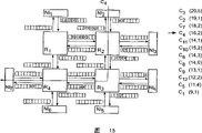
图9显示的是包含4个路由器R1~R4以及7个网络接口NI(NI1~NI7)的芯片上网络实例。在这里并未显示与网络接口相连的IP块。作为实例,选择了12个连接C1~C12。这些连接用于在与网络接口NI相连的IP模块(未显示)之间传输数据,由此,这些连接始终设置在两个网络接口NI之间。为了简单起见,我们假设所有连接都是单向的(包括一个信道),但在实践中同样可以存在双向连接(两个信道)。例如,连接C1始于NI1,并且经过R1和R4到达NI6。类似,连接C2经过NI1、R1、R2、R3和NI4。连接C3经过NI1、R1、R2和NI2。连接C4经过NI2、R2、R3和NI7。连接C5经过NI2、R2以及NI3。连接C6经过NI3、R2、R1以及NI1。连接C7经过NI3、R2、R3以及NI5、连接C8经过NI4、R3以及NI5。连接C9经过NI5、R3、R4、R1以及NI1。连接C10经过NI6、R4、R3、R2以及NI2。连接C11经过NI7、R4、R3、R2以及NI3。连接C12经过NI7、R4、R1以及NI1。必须为每一个连接保留多个时隙。在图9的右侧列出了这些数量,也就是说,连接C1~C12分别需要1、1、5、2、4、3、2、6、1、2、1和2个时隙。FIG. 9 shows an example of a network on chip including 4 routers R1-R4 and 7 network interfaces NI (NI1-NI7). The IP blocks connected to the network interfaces are not shown here. As an example, 12 connections C1-C12 are selected. These connections are used to transfer data between IP modules (not shown) connected to the network interfaces NI, whereby these connections are always arranged between two network interfaces NI. For simplicity, we assume that all connections are unidirectional (including one channel), but in practice bidirectional connections (two channels) can exist as well. For example, connection C1 starts at NI1 and goes through R1 and R4 to NI6. Similarly, connection C2 goes through NI1, R1, R2, R3 and NI4. Connection C3 goes through NI1, R1, R2 and NI2. Connection C4 goes through NI2, R2, R3 and NI7. Connection C5 goes through NI2, R2 and NI3. Connection C6 goes through NI3, R2, R1 and NI1. Connection C7 passes through NI3, R2, R3 and NI5, and connection C8 passes through NI4, R3 and NI5. Connection C9 goes through NI5, R3, R4, R1 and NI1. Connection C10 goes through NI6, R4, R3, R2 and NI2. Connection C11 goes through NI7, R4, R3, R2 and NI3. Connection C12 goes through NI7, R4, R1 and NI1. Multiple slots must be reserved for each connection. These quantities are listed on the right side of Fig. 9, that is to say, connections C1-C12 require 1, 1, 5, 2, 4, 3, 2, 6, 1, 2, 1 and 2 time slots respectively.
图10显示的是根据图9的芯片上网络。该算法以计算链路权重开始。这通过为每一条链路计算使用该链路的所有连接所请求的时隙数量之和来进行。此外,单独为每一个方向执行该操作。这些链路由圆圈所环绕,其链路权重结果则是紧临该圆圈显示的。例如,对从R2到R3的链路来说,将连接C2、C4和C7请求的时隙相加。由此得到的结果是链路权重1(C2)+2(C4)+2(C7)=5。NI1与R1之间的链路需要7个时隙,R1与NI1之间的链路则需要6个时隙,依此类推。FIG. 10 shows the network on chip according to FIG. 9 . The algorithm starts by calculating link weights. This is done by calculating for each link the sum of the number of timeslots requested by all connections using that link. Also, do this for each orientation separately. These links are surrounded by a circle, and their link weight results are displayed next to the circle. For example, for the link from R2 to R3, the time slots requested by connections C2, C4 and C7 are summed. The result thus obtained is link weight 1(C2)+2(C4)+2(C7)=5. The link between NI1 and R1 needs 7 time slots, the link between R1 and NI1 needs 6 time slots, and so on.
图11显示的是根据图10的芯片上网络。该算法计算的是连接权重。在连接权重公式中,a1=1、a2=0并且a3=0(也就是对链路权重求和)。作为选择,可以选择不同的值。在图11的右侧显示了连接权重的结果。例如,连接C1的权重是链路NI1到R1、R1到R4以及R4到NI10的权重总和,其结果是7+1+1=9。然后,关于计算得到的权重因数,以降序对这些连接进行分类,并且将会根据该顺序来进行调度。FIG. 11 shows the network on chip according to FIG. 10 . The algorithm calculates the connection weights. In the connection weight formula, a1 = 1, a2 = 0 and a3 = 0 (ie summing the link weights). Alternatively, different values can be chosen. The results for the connection weights are shown on the right side of Figure 11. For example, the weight of connection C1 is the sum of the weights of links NI1 to R1, R1 to R4 and R4 to NI10, which results in 7+1+1=9. These connections are then sorted in descending order with respect to the calculated weighting factors and will be scheduled according to this order.
在图12~23中,显示了所有连接C1~C12的时隙分配。假设首先分配的是所需的空闲时隙。时隙表的大小可以是例如9个时隙。时隙表中描述的数量与分配了这些时隙的相应连接C1~C12是对应的。In Figures 12-23, the time slot allocations for all connections C1-C12 are shown. It is assumed that the required free slots are allocated first. The size of the slot table may be eg 9 slots. The numbers described in the time slot table correspond to the corresponding connections C1-C12 to which these time slots are allocated.
图12、13、14、15、16、17、18、19、20、21、22、23分别显示的是连接C3、C2、C7、C4、C11、C10、C6、C8、C9、C12、C5和C1的分配。Figures 12, 13, 14, 15, 16, 17, 18, 19, 20, 21, 22, and 23 respectively show connections C3, C2, C7, C4, C11, C10, C6, C8, C9, C12, and C5 and assignment of C1.
根据图12,对需要5个时隙的连接C3来说,所有时隙都是空闲的,因此,为其分配的是链路NI1到R1的时隙1~5,链路R1到R2的时隙2~6以及链路R2到NI2的时隙3~8。根据图13,对需要一个时隙的连接C2来说,在第一链路中已经保留了前5个时隙,因此,在沿着该路径的相应时隙表中其保留时隙6、7、8和9。根据图14,需要2个时隙的连接C7在前两个时隙中并未出现冲突,由此分配这些时隙。根据图15,由于在第二链路(R2到R3)中为C7保留了前两个时隙,因此,需要2个时隙的连接C4只能保留时隙3和4。根据图16,C11同样也是没有冲突,并且在网络接口NI7和路由器R4的链路的时隙表中保留第一个时隙,以及在其他的链路的时隙表中保留连续的时隙。According to Fig. 12, for the connection C3 which needs 5 time slots, all the time slots are free, therefore, it is assigned the time slots 1-5 of the link NI1 to R1, and the time slots of the link R1 to R2. slots 2-6 and slots 3-8 of link R2 to NI2. According to Fig. 13, for the connection C2 requiring a time slot, the first 5 time slots have been reserved in the first link, therefore, it reserves
然而,对根据图17需要2个时隙的连接C10来说,前4个时隙与链路R2到NI2中为C3保留的时隙相冲突,因此,最先的空闲时隙是5和6。如图18所示,连接C6在网络接口NI3以及路由器R2的链路中分配了三个时隙,即时隙3~5;在路由器R2和路由器R1的链路的时隙表中分配了时隙4~6;此外还在路由器R1和网络接口NI1的链路的时隙表中分配了时隙5~7。根据图19,因此,连接C8在网络接口NI4和路由器R3的链路中分配了6个时隙,即时隙1、4~8;而在路由器R3和网络接口NI5的链路的时隙表中则分配了时隙2、5~9,因为在路由器R3和网络接口NI5的链路的时隙表中,时隙3~4已被分配或是预留给连接7。However, for connection C10 which requires 2 slots according to Figure 17, the first 4 slots collide with the slots reserved for C3 in link R2 to NI2, so the first free slots are 5 and 6 . As shown in Figure 18, connection C6 allocates three time slots in the network interface NI3 and the link of router R2, that is,
如图20所示,连接C9在网络接口NI5和路由器R3的链路中分配了一个时隙,即时隙1;在路由器R3和路由器R4的链路的时隙表中分配了时隙2;在路由器R4和路由器R5的链路的时隙表中分配了时隙3;并且在路由器R1和网络接口NI1的链路的时隙表中分配了时隙4。根据图21,连接C12在网络接口NI7和路由器R4的链路中分配了两个时隙,即时隙6~7;在路由器R4和路由器R1的链路中分配了时隙7~8;而在路由器R1和网络接口NI1的链路的时隙表中则分配了时隙8~9,因为在路由器R1和网络接口NI1的链路的时隙表中,时隙4以及时隙5~7已经分别被分配给了连接C9和C6。As shown in Figure 20, connection C9 allocates a time slot in the link between network interface NI5 and router R3, that is,
如图22所示,连接C5在网络接口NI2和路由器R2的链路的时隙表中分配了4个时隙,即时隙1~2和5~6;并且在路由器R2和网络接口NI3的链路的时隙表中分配了时隙2~3和6~7,因为在网络接口NI2和路由器R2的链路的时隙表中,时隙3-4已被分配给连接C4。As shown in Figure 22, connection C5 allocates 4 time slots in the time slot table of the link between network interface NI2 and router R2, that is, slots 1-2 and 5-6; and the link between router R2 and network interface NI3 The time slots 2-3 and 6-7 are allocated in the slot table of the link of the network interface NI2 and the router R2, because the time slots 3-4 have been allocated to the connection C4 in the slot table of the link of the network interface NI2 and the router R2.
最后,在图23中,连接C1在网络接口NI1和路由器R1的链路的时隙表中分配了一个时隙,即时隙7;在路由器R1和路由器R4的链路的时隙表中分配了时隙8;在路由器R4和网络接口NI6的链路的时隙表中分配了时隙9。相应的,在图23中显示的是时隙分配的最终结果。Finally, in Figure 23, connection C1 is assigned a slot, namely
虽然在上文中将时隙分配单元描述成是安装在网络接口中的,但是所述时隙分配单元也可以安装在网络内部的路由器中。Although the time slot allocating unit has been described above as being installed in a network interface, the time slot allocating unit may also be installed in a router inside the network.
上述时隙分配单元不但适用于单个芯片上的网络,而且还适用于包含了若干个单独的集成电路的任何数据处理设备或多芯片网络。The time slot allocation unit described above is applicable not only to a network on a single chip, but also to any data processing device or multi-chip network comprising several individual integrated circuits.
应该指出的是,上述实施例是说明性而不是限制性的,并且本领域技术人员能够在不脱离附加权利要求范围的情况下设计出很多替换实施例。在权利要求中,放置在圆括号之间的任何参考符号不应解释成是对权利要求进行限制。单词“包括”并不排除存在权利要求所列举的部件或步骤之外的其他部件或步骤。部件之前的单词“一”或“一个”并不排除存在多个此类部件。在列举了若干个装置的设备权利要求中,其中若干个装置可以借助同一个硬件项来实现。虽然某些措施是在互不相同的从属权利要求中叙述的,但这并不代表不能有效使用这些措施的组合。It should be noted that the above-mentioned embodiments illustrate rather than limit, and that those skilled in the art will be able to design many alternative embodiments without departing from the scope of the appended claims. In the claims, any reference signs placed between parentheses shall not be construed as limiting the claim. The word "comprising" does not exclude the presence of other elements or steps than those listed in a claim. The word "a" or "an" preceding an element does not exclude the presence of a plurality of such elements. In a device claim enumerating several means, several of these means can be embodied by one and the same item of hardware. The mere fact that certain measures are recited in mutually different dependent claims does not indicate that a combination of these measures cannot be used to advantage.
此外,权利要求中的任何参考符号都不应被解释成是对权利要求的范围进行限制。Furthermore, any reference signs in the claims shall not be construed as limiting the scope of the claims.
Claims (17)
Applications Claiming Priority (3)
| Application Number | Priority Date | Filing Date | Title |
|---|---|---|---|
| EP04101400 | 2004-04-05 | ||
| EP04101400.2 | 2004-04-05 | ||
| PCT/IB2005/050999 WO2005099187A1 (en) | 2004-04-05 | 2005-03-23 | Integrated circuit and method for time slot allocation |
Publications (2)
| Publication Number | Publication Date |
|---|---|
| CN1947387A true CN1947387A (en) | 2007-04-11 |
| CN1947387B CN1947387B (en) | 2010-04-14 |
Family
ID=34962008
Family Applications (1)
| Application Number | Title | Priority Date | Filing Date |
|---|---|---|---|
| CN2005800121325A Expired - Lifetime CN1947387B (en) | 2004-04-05 | 2005-03-23 | Integrated circuit and method for time slot allocation |
Country Status (8)
| Country | Link |
|---|---|
| US (1) | US7564865B2 (en) |
| EP (1) | EP1735966B1 (en) |
| JP (1) | JP4686539B2 (en) |
| KR (1) | KR101125647B1 (en) |
| CN (1) | CN1947387B (en) |
| AT (1) | ATE403314T1 (en) |
| DE (1) | DE602005008573D1 (en) |
| WO (1) | WO2005099187A1 (en) |
Families Citing this family (53)
| Publication number | Priority date | Publication date | Assignee | Title |
|---|---|---|---|---|
| US20080043757A1 (en) * | 2004-08-12 | 2008-02-21 | Koninklijke Philips Electronics, N.V. | Integrated Circuit And Method For Packet Switching Control |
| JP2008536391A (en) * | 2005-04-07 | 2008-09-04 | コーニンクレッカ フィリップス エレクトロニクス エヌ ヴィ | Network-on-chip environment and method for reducing latency |
| US20090122703A1 (en) * | 2005-04-13 | 2009-05-14 | Koninklijke Philips Electronics, N.V. | Electronic Device and Method for Flow Control |
| JP4756158B2 (en) * | 2005-05-26 | 2011-08-24 | エスティー‐エリクソン、ソシエテ、アノニム | Communication resource allocation electronic device and method |
| US20080232387A1 (en) * | 2005-07-19 | 2008-09-25 | Koninklijke Philips Electronics N.V. | Electronic Device and Method of Communication Resource Allocation |
| US8301885B2 (en) * | 2006-01-27 | 2012-10-30 | Fts Computertechnik Gmbh | Time-controlled secure communication |
| WO2008004187A2 (en) * | 2006-07-05 | 2008-01-10 | Nxp B.V. | Electronic device, system on chip and method of monitoring data traffic |
| US9003292B2 (en) * | 2006-07-06 | 2015-04-07 | LiveAction, Inc. | System and method for network topology and flow visualization |
| KR100737943B1 (en) * | 2006-09-13 | 2007-07-13 | 삼성전자주식회사 | Network-on-chip response signal control device and method |
| WO2008038235A2 (en) * | 2006-09-27 | 2008-04-03 | Ecole Polytechnique Federale De Lausanne (Epfl) | Method to manage the load of peripheral elements within a multicore system |
| US20090307408A1 (en) * | 2008-06-09 | 2009-12-10 | Rowan Nigel Naylor | Peer-to-Peer Embedded System Communication Method and Apparatus |
| US8108908B2 (en) * | 2008-10-22 | 2012-01-31 | International Business Machines Corporation | Security methodology to prevent user from compromising throughput in a highly threaded network on a chip processor |
| JP5163462B2 (en) * | 2008-12-09 | 2013-03-13 | 富士通株式会社 | Network device, edge router and packet communication system |
| US7957410B2 (en) * | 2008-12-10 | 2011-06-07 | Palo Alto Research Center Incorporated | Proportionally fair-share time slot reservations with a fast increase, slow decrease rate controller |
| FR2948840B1 (en) * | 2009-07-29 | 2011-09-16 | Kalray | CHIP COMMUNICATION NETWORK WITH SERVICE WARRANTY |
| JP5397167B2 (en) * | 2009-11-05 | 2014-01-22 | 富士通株式会社 | Time slot allocation method, program, and apparatus |
| JP4820466B2 (en) * | 2010-01-25 | 2011-11-24 | パナソニック株式会社 | Semiconductor system, repeater and chip circuit |
| JP5375661B2 (en) * | 2010-02-24 | 2013-12-25 | 富士通株式会社 | Route assignment apparatus and route assignment method |
| US9304782B2 (en) * | 2010-05-03 | 2016-04-05 | Pluribus Networks, Inc. | Network switch, systems, and servers implementing boot image delivery |
| US8885510B2 (en) | 2012-10-09 | 2014-11-11 | Netspeed Systems | Heterogeneous channel capacities in an interconnect |
| US9007920B2 (en) * | 2013-01-18 | 2015-04-14 | Netspeed Systems | QoS in heterogeneous NoC by assigning weights to NoC node channels and using weighted arbitration at NoC nodes |
| US9571402B2 (en) * | 2013-05-03 | 2017-02-14 | Netspeed Systems | Congestion control and QoS in NoC by regulating the injection traffic |
| US9320036B2 (en) * | 2013-07-17 | 2016-04-19 | Cisco Technology, Inc. | Installation of time slots for sending a packet through an ARC chain topology network |
| US9471726B2 (en) | 2013-07-25 | 2016-10-18 | Netspeed Systems | System level simulation in network on chip architecture |
| US9473388B2 (en) | 2013-08-07 | 2016-10-18 | Netspeed Systems | Supporting multicast in NOC interconnect |
| US9699079B2 (en) | 2013-12-30 | 2017-07-04 | Netspeed Systems | Streaming bridge design with host interfaces and network on chip (NoC) layers |
| US9473415B2 (en) | 2014-02-20 | 2016-10-18 | Netspeed Systems | QoS in a system with end-to-end flow control and QoS aware buffer allocation |
| US9742630B2 (en) | 2014-09-22 | 2017-08-22 | Netspeed Systems | Configurable router for a network on chip (NoC) |
| US9571341B1 (en) | 2014-10-01 | 2017-02-14 | Netspeed Systems | Clock gating for system-on-chip elements |
| US9660942B2 (en) | 2015-02-03 | 2017-05-23 | Netspeed Systems | Automatic buffer sizing for optimal network-on-chip design |
| US9444702B1 (en) | 2015-02-06 | 2016-09-13 | Netspeed Systems | System and method for visualization of NoC performance based on simulation output |
| US9928204B2 (en) | 2015-02-12 | 2018-03-27 | Netspeed Systems, Inc. | Transaction expansion for NoC simulation and NoC design |
| US9568970B1 (en) | 2015-02-12 | 2017-02-14 | Netspeed Systems, Inc. | Hardware and software enabled implementation of power profile management instructions in system on chip |
| US10348563B2 (en) | 2015-02-18 | 2019-07-09 | Netspeed Systems, Inc. | System-on-chip (SoC) optimization through transformation and generation of a network-on-chip (NoC) topology |
| US10050843B2 (en) | 2015-02-18 | 2018-08-14 | Netspeed Systems | Generation of network-on-chip layout based on user specified topological constraints |
| US9825809B2 (en) | 2015-05-29 | 2017-11-21 | Netspeed Systems | Dynamically configuring store-and-forward channels and cut-through channels in a network-on-chip |
| US9864728B2 (en) | 2015-05-29 | 2018-01-09 | Netspeed Systems, Inc. | Automatic generation of physically aware aggregation/distribution networks |
| US10218580B2 (en) | 2015-06-18 | 2019-02-26 | Netspeed Systems | Generating physically aware network-on-chip design from a physical system-on-chip specification |
| US10666578B2 (en) * | 2016-09-06 | 2020-05-26 | Taiwan Semiconductor Manufacturing Company Limited | Network-on-chip system and a method of generating the same |
| US10452124B2 (en) | 2016-09-12 | 2019-10-22 | Netspeed Systems, Inc. | Systems and methods for facilitating low power on a network-on-chip |
| US20180159786A1 (en) | 2016-12-02 | 2018-06-07 | Netspeed Systems, Inc. | Interface virtualization and fast path for network on chip |
| US10313269B2 (en) | 2016-12-26 | 2019-06-04 | Netspeed Systems, Inc. | System and method for network on chip construction through machine learning |
| US10063496B2 (en) | 2017-01-10 | 2018-08-28 | Netspeed Systems Inc. | Buffer sizing of a NoC through machine learning |
| US10084725B2 (en) | 2017-01-11 | 2018-09-25 | Netspeed Systems, Inc. | Extracting features from a NoC for machine learning construction |
| US10469337B2 (en) | 2017-02-01 | 2019-11-05 | Netspeed Systems, Inc. | Cost management against requirements for the generation of a NoC |
| US10298485B2 (en) | 2017-02-06 | 2019-05-21 | Netspeed Systems, Inc. | Systems and methods for NoC construction |
| US11144457B2 (en) | 2018-02-22 | 2021-10-12 | Netspeed Systems, Inc. | Enhanced page locality in network-on-chip (NoC) architectures |
| US10983910B2 (en) * | 2018-02-22 | 2021-04-20 | Netspeed Systems, Inc. | Bandwidth weighting mechanism based network-on-chip (NoC) configuration |
| US10896476B2 (en) | 2018-02-22 | 2021-01-19 | Netspeed Systems, Inc. | Repository of integration description of hardware intellectual property for NoC construction and SoC integration |
| US10547514B2 (en) | 2018-02-22 | 2020-01-28 | Netspeed Systems, Inc. | Automatic crossbar generation and router connections for network-on-chip (NOC) topology generation |
| US11176302B2 (en) | 2018-02-23 | 2021-11-16 | Netspeed Systems, Inc. | System on chip (SoC) builder |
| US11023377B2 (en) | 2018-02-23 | 2021-06-01 | Netspeed Systems, Inc. | Application mapping on hardened network-on-chip (NoC) of field-programmable gate array (FPGA) |
| JP7710957B2 (en) * | 2021-10-14 | 2025-07-22 | 株式会社東芝 | COMMUNICATION DEVICE, COMMUNICATION METHOD, PROGRAM, AND COMMUNICATION SYSTEM |
Family Cites Families (9)
| Publication number | Priority date | Publication date | Assignee | Title |
|---|---|---|---|---|
| US5519836A (en) * | 1994-03-25 | 1996-05-21 | At&T Corp. | Method of on-line permanent virtual circuit routing |
| CN1164303A (en) * | 1994-07-15 | 1997-11-05 | 艾利森电话股份有限公司 | Channel hopping in radio communications system |
| JP2960365B2 (en) * | 1997-02-26 | 1999-10-06 | 株式会社ワイ・アール・ピー移動通信基盤技術研究所 | Handoff method and mobile communication network with handoff function |
| CN1218543C (en) * | 2000-10-10 | 2005-09-07 | 辐射网络公司 | communication grid |
| EP1286268A1 (en) * | 2001-08-21 | 2003-02-26 | Alcatel | Integrated circuit with allocation of address ranges |
| US6958986B2 (en) * | 2002-01-10 | 2005-10-25 | Harris Corporation | Wireless communication system with enhanced time slot allocation and interference avoidance/mitigation features and related methods |
| WO2006051471A1 (en) * | 2004-11-09 | 2006-05-18 | Koninklijke Philips Electronics N.V. | Electronic device and method of communication resource allocation |
| EP1869844A1 (en) * | 2005-04-06 | 2007-12-26 | Koninklijke Philips Electronics N.V. | Network-on-chip environment and method for reduction of latency |
| JP2008536391A (en) * | 2005-04-07 | 2008-09-04 | コーニンクレッカ フィリップス エレクトロニクス エヌ ヴィ | Network-on-chip environment and method for reducing latency |
-
2005
- 2005-03-23 KR KR1020067020792A patent/KR101125647B1/en not_active Expired - Fee Related
- 2005-03-23 US US10/599,561 patent/US7564865B2/en not_active Expired - Lifetime
- 2005-03-23 DE DE602005008573T patent/DE602005008573D1/en not_active Expired - Lifetime
- 2005-03-23 AT AT05709078T patent/ATE403314T1/en not_active IP Right Cessation
- 2005-03-23 EP EP05709078A patent/EP1735966B1/en not_active Expired - Lifetime
- 2005-03-23 CN CN2005800121325A patent/CN1947387B/en not_active Expired - Lifetime
- 2005-03-23 JP JP2007506873A patent/JP4686539B2/en not_active Expired - Lifetime
- 2005-03-23 WO PCT/IB2005/050999 patent/WO2005099187A1/en not_active Ceased
Also Published As
| Publication number | Publication date |
|---|---|
| EP1735966A1 (en) | 2006-12-27 |
| DE602005008573D1 (en) | 2008-09-11 |
| US20070195748A1 (en) | 2007-08-23 |
| KR101125647B1 (en) | 2012-03-27 |
| WO2005099187A1 (en) | 2005-10-20 |
| ATE403314T1 (en) | 2008-08-15 |
| EP1735966B1 (en) | 2008-07-30 |
| JP2007532075A (en) | 2007-11-08 |
| US7564865B2 (en) | 2009-07-21 |
| JP4686539B2 (en) | 2011-05-25 |
| KR20070023678A (en) | 2007-02-28 |
| CN1947387B (en) | 2010-04-14 |
Similar Documents
| Publication | Publication Date | Title |
|---|---|---|
| CN1947387A (en) | Integrated circuit and method for time slot allocation | |
| CN100342370C (en) | Integrated circuit and method for exchanging data | |
| CN103348640B (en) | Relay | |
| CN101223745A (en) | Electronic device and method for communication resource allocation | |
| JP2008535435A (en) | Network-on-chip environment and delay reduction method | |
| US20080181115A1 (en) | System for transmitting data within a network between nodes of the network and flow control process for transmitting the data | |
| CN102523764A (en) | Relay device | |
| CN1497911A (en) | packet communication device | |
| CN1929688A (en) | Method of setting a network path and wireless station | |
| CN1606291A (en) | Network-processor accelerator | |
| CN112291791B (en) | Power communication mesh bandwidth resource allocation method based on 5G slice | |
| CN1965606B (en) | Integrated circuit and method for time slot allocation | |
| JP4756158B2 (en) | Communication resource allocation electronic device and method | |
| CN101053225A (en) | Electronic device and method of communication resource allocation | |
| CN1179214C (en) | Scalable apparatus and method for increasing throughput in a multi-layer minimal logical network using multiple control lines | |
| CN1442012A (en) | Communication control method and device | |
| CN102640462B (en) | Integrated circuit for Buffering Service request is arranged | |
| CN1703876A (en) | Distribution compartments for an efficient and failsafe traffic distribution in a packet-switched network | |
| CN1905426A (en) | Method of light plate lower branch time slot time division optimizing configuration of SDH system |
Legal Events
| Date | Code | Title | Description |
|---|---|---|---|
| C06 | Publication | ||
| PB01 | Publication | ||
| C10 | Entry into substantive examination | ||
| SE01 | Entry into force of request for substantive examination | ||
| C14 | Grant of patent or utility model | ||
| GR01 | Patent grant | ||
| CP03 | Change of name, title or address |
Address after: 52 high-tech park, 5656AG, Edelhofen, Netherlands Patentee after: KONINKLIJKE PHILIPS N.V. Address before: Holland Ian Deho Finn Patentee before: KONINKLIJKE PHILIPS ELECTRONICS N.V. |
|
| CP03 | Change of name, title or address | ||
| TR01 | Transfer of patent right |
Effective date of registration: 20230425 Address after: Maine Patentee after: Network System Technology Co.,Ltd. Address before: 52 high-tech park, 5656AG, Edelhofen, Netherlands Patentee before: KONINKLIJKE PHILIPS N.V. |
|
| TR01 | Transfer of patent right | ||
| CX01 | Expiry of patent term |
Granted publication date: 20100414 |
|
| CX01 | Expiry of patent term |