CN1916930A - Information-recorded medium containing a holographically-recorded bar code and associated methods - Google Patents
Information-recorded medium containing a holographically-recorded bar code and associated methods Download PDFInfo
- Publication number
- CN1916930A CN1916930A CN 200610121524 CN200610121524A CN1916930A CN 1916930 A CN1916930 A CN 1916930A CN 200610121524 CN200610121524 CN 200610121524 CN 200610121524 A CN200610121524 A CN 200610121524A CN 1916930 A CN1916930 A CN 1916930A
- Authority
- CN
- China
- Prior art keywords
- bar code
- photosensitive layer
- hologram
- holographic recording
- image
- Prior art date
- Legal status (The legal status is an assumption and is not a legal conclusion. Google has not performed a legal analysis and makes no representation as to the accuracy of the status listed.)
- Pending
Links
- 238000000034 method Methods 0.000 title claims abstract description 56
- 230000001427 coherent effect Effects 0.000 claims description 25
- 230000005855 radiation Effects 0.000 claims description 9
- 230000008520 organization Effects 0.000 claims description 8
- 238000004519 manufacturing process Methods 0.000 claims description 6
- 230000002452 interceptive effect Effects 0.000 claims description 2
- 238000001228 spectrum Methods 0.000 abstract description 6
- 230000005670 electromagnetic radiation Effects 0.000 abstract description 2
- 239000010410 layer Substances 0.000 description 18
- 239000000463 material Substances 0.000 description 15
- 230000005540 biological transmission Effects 0.000 description 13
- 108010010803 Gelatin Proteins 0.000 description 10
- 229920000159 gelatin Polymers 0.000 description 10
- 239000008273 gelatin Substances 0.000 description 10
- 235000019322 gelatine Nutrition 0.000 description 10
- 235000011852 gelatine desserts Nutrition 0.000 description 10
- 230000003287 optical effect Effects 0.000 description 9
- 238000007639 printing Methods 0.000 description 9
- 239000000839 emulsion Substances 0.000 description 8
- 238000003384 imaging method Methods 0.000 description 7
- 239000011159 matrix material Substances 0.000 description 7
- KFZMGEQAYNKOFK-UHFFFAOYSA-N Isopropanol Chemical compound CC(C)O KFZMGEQAYNKOFK-UHFFFAOYSA-N 0.000 description 6
- 239000002131 composite material Substances 0.000 description 6
- 238000001093 holography Methods 0.000 description 6
- 230000008569 process Effects 0.000 description 6
- LFQSCWFLJHTTHZ-UHFFFAOYSA-N Ethanol Chemical compound CCO LFQSCWFLJHTTHZ-UHFFFAOYSA-N 0.000 description 5
- 239000011521 glass Substances 0.000 description 5
- 230000003068 static effect Effects 0.000 description 5
- 239000000126 substance Substances 0.000 description 5
- 238000012360 testing method Methods 0.000 description 5
- XLYOFNOQVPJJNP-UHFFFAOYSA-N water Substances O XLYOFNOQVPJJNP-UHFFFAOYSA-N 0.000 description 5
- 238000005516 engineering process Methods 0.000 description 4
- 239000005337 ground glass Substances 0.000 description 4
- 238000010998 test method Methods 0.000 description 4
- 238000009792 diffusion process Methods 0.000 description 3
- 238000003475 lamination Methods 0.000 description 3
- 238000004806 packaging method and process Methods 0.000 description 3
- 230000000007 visual effect Effects 0.000 description 3
- 241001479434 Agfa Species 0.000 description 2
- 230000008901 benefit Effects 0.000 description 2
- 230000015572 biosynthetic process Effects 0.000 description 2
- 230000008859 change Effects 0.000 description 2
- 239000003086 colorant Substances 0.000 description 2
- 238000001035 drying Methods 0.000 description 2
- 230000014509 gene expression Effects 0.000 description 2
- 238000005286 illumination Methods 0.000 description 2
- 230000001678 irradiating effect Effects 0.000 description 2
- 238000002955 isolation Methods 0.000 description 2
- 238000005259 measurement Methods 0.000 description 2
- 230000007246 mechanism Effects 0.000 description 2
- 229910052709 silver Inorganic materials 0.000 description 2
- 239000004332 silver Substances 0.000 description 2
- 230000008961 swelling Effects 0.000 description 2
- 238000012546 transfer Methods 0.000 description 2
- 208000035126 Facies Diseases 0.000 description 1
- 241001274660 Modulus Species 0.000 description 1
- 206010034972 Photosensitivity reaction Diseases 0.000 description 1
- BQCADISMDOOEFD-UHFFFAOYSA-N Silver Chemical compound [Ag] BQCADISMDOOEFD-UHFFFAOYSA-N 0.000 description 1
- FNYLWPVRPXGIIP-UHFFFAOYSA-N Triamterene Chemical compound NC1=NC2=NC(N)=NC(N)=C2N=C1C1=CC=CC=C1 FNYLWPVRPXGIIP-UHFFFAOYSA-N 0.000 description 1
- XKRFYHLGVUSROY-UHFFFAOYSA-N argon Substances [Ar] XKRFYHLGVUSROY-UHFFFAOYSA-N 0.000 description 1
- 229910052786 argon Inorganic materials 0.000 description 1
- QVQLCTNNEUAWMS-UHFFFAOYSA-N barium oxide Chemical compound [Ba]=O QVQLCTNNEUAWMS-UHFFFAOYSA-N 0.000 description 1
- 229910001864 baryta Inorganic materials 0.000 description 1
- 239000008280 blood Substances 0.000 description 1
- 210000004369 blood Anatomy 0.000 description 1
- 239000007767 bonding agent Substances 0.000 description 1
- 239000000969 carrier Substances 0.000 description 1
- 239000011248 coating agent Substances 0.000 description 1
- 238000000576 coating method Methods 0.000 description 1
- 150000001875 compounds Chemical class 0.000 description 1
- 238000012790 confirmation Methods 0.000 description 1
- 230000021615 conjugation Effects 0.000 description 1
- 238000010276 construction Methods 0.000 description 1
- 230000008602 contraction Effects 0.000 description 1
- 238000013461 design Methods 0.000 description 1
- 238000011161 development Methods 0.000 description 1
- 230000009365 direct transmission Effects 0.000 description 1
- 238000009826 distribution Methods 0.000 description 1
- 230000000694 effects Effects 0.000 description 1
- 239000005357 flat glass Substances 0.000 description 1
- 230000006870 function Effects 0.000 description 1
- 230000003760 hair shine Effects 0.000 description 1
- 230000036541 health Effects 0.000 description 1
- CPLXHLVBOLITMK-UHFFFAOYSA-N magnesium oxide Inorganic materials [Mg]=O CPLXHLVBOLITMK-UHFFFAOYSA-N 0.000 description 1
- 239000000395 magnesium oxide Substances 0.000 description 1
- AXZKOIWUVFPNLO-UHFFFAOYSA-N magnesium;oxygen(2-) Chemical compound [O-2].[Mg+2] AXZKOIWUVFPNLO-UHFFFAOYSA-N 0.000 description 1
- 229910052751 metal Inorganic materials 0.000 description 1
- 239000002184 metal Substances 0.000 description 1
- 239000000203 mixture Substances 0.000 description 1
- 238000012856 packing Methods 0.000 description 1
- 239000002245 particle Substances 0.000 description 1
- 230000036211 photosensitivity Effects 0.000 description 1
- 238000012545 processing Methods 0.000 description 1
- 238000003908 quality control method Methods 0.000 description 1
- 239000012925 reference material Substances 0.000 description 1
- 238000001028 reflection method Methods 0.000 description 1
- 230000011514 reflex Effects 0.000 description 1
- 230000001105 regulatory effect Effects 0.000 description 1
- 230000010076 replication Effects 0.000 description 1
- 238000011160 research Methods 0.000 description 1
- 230000035945 sensitivity Effects 0.000 description 1
- -1 silver halide Chemical class 0.000 description 1
- 239000002356 single layer Substances 0.000 description 1
- 238000003860 storage Methods 0.000 description 1
- 230000002747 voluntary effect Effects 0.000 description 1
Images


Landscapes
- Holo Graphy (AREA)
Abstract
An information-recorded medium that contains a holographically-recorded bar code and a method for using this medium to achieve enhanced security and authentication of bar code readings in commerce are described. The holographically-recorded bar code is virtually impossible to copy by non-holographic means and is readable using conventional bar code scanners that are currently in use. The holographically-recorded bar code can be made either visible or invisible to the human eye and can be made responsive to electromagnetic radiation in the visible, ultraviolet, and infrared regions of the spectrum.
Description
Technical field
The present invention relates to a kind of information recording carrier that comprises the holographic recording bar code, described bar code can be read and be difficult to and forge with conventional bar code reader/scanner.The invention still further relates to relevant method.Described medium and correlation technique especially can be used as safety equipment, and can be used to identify the purpose of all business type bar codes.
Background technology
Holography and hologram
Holographic photography is a kind of optical information file layout.Its general principle is in many documents, and for example E.N.Leith and J.Upatnieks be at SCIENTIFIC AMERICAN, and 212, No.6 describes in 24-35 (June, 1965) " taking a picture by laser " to some extent.In brief, being used for the collimated light of laser freely illuminates and waits to take a picture or the object of imaging, places a photosensitive recording medium such as photographic negative and accepts from the light of this object reflection.On the object each light of naming a person for a particular job reflexes to whole recording medium, and each point on this record is accepted the light from whole object.This catoptrical light beam is called object beam.Simultaneously, the part of collimated light is directly launched by this object to this medium by mirror.This light beam is called reference beams.Being recorded in record on the benchmark is by shining the interference image that reference beams on the medium and object beam interact and produce.When shining treated recording medium and suitable method subsequently and observe, from the light of radiation source by the hologram diffraction, and produced originally wave front when object arrives medium again, like this, hologram is similar to a window, can observe (comprising parallax) virtual image of this object with the form of complete three-dimensional by this window.
Form hologram and be called transmission hologram, light beam hologram before being also referred to as by making reference beams and object beam enter recording medium from the same side.Object beam and reference beams interact in recording medium and have formed the material interference striped with different refractivity, and these interference fringes and recording medium plane are orthogonal thereto or near quadrature.When with the playback of viewed in transmitted light hologram, these interference fringes have produced observed virtual image with optical diffraction.Such transmission hologram can produce with method well known in the art, as United States Patent (USP) 3,506,327; Disclosed method in 3,838,903 and 3,894,787, these documents are all included this paper in as a reference.
Enter recording medium by reference beams and object beam are advanced from relative side, so they are with opposite substantially direction motion, the hologram of formation is called reflection hologram, is also referred to as bundle hologram backlight.Object beam and reference beams interact in recording medium and have formed the material interference striped with different refractivity, plane and recording medium plane almost parallel that these interference fringes form.When the hologram playback, these interference fringes play the mirror image effect, and incident light is turned back to the observer.Therefore, hologram is in the reflection mode but not transmission mode is viewed.Because the wavelength sensitivity of this type of hologram is very high, therefore available white light comes reconstruct.United States Patent (USP) 3,532 discloses in 406 and has used the reflection hologram that produces from the axle method, and the document is included this paper in as a reference.
Bar code
Since first bar code appears in nineteen fifty generation, developed the symbolism or the language of many different bar codes.Add up the known symbolism that about 250 kinds of bar codes are arranged at last; But having only seldom in these symbolisms, amount is used at present.Linear 1D (one dimension of conduct of discussing below and bidimensional opposition) symbolism is widely used bar code type always.Prevailing 1D symbolism is a code 39, is introduced by defence and auto industry; Universial Product Code (Universal Product Code) (U.P.C.), is at first used by the supermarket in the 1970's; Codabar uses in blood bank in early days, Interleaved 2-of 5 (interweave five in get two ITF), and code 28.
Each symbolism all have its oneself character (as, letter, numeral, other character) and coding rule, and to the rule of others as printing and bug check.The mode difference that various bar code symbologies adopt to the data coding.For example, some is only to numerical coding, other to numeral, letter and the coding of punctuation mark seldom; Also have some that 128-is provided character, in addition the 256-character, the coding of ASCII collection.
Bar code scanner is the electrical-optical system, comprises symbol is shone the device of measuring then from the light of symbol reflected.Change reflected light data into digital form from analog form,, be transferred to computing machine then, analyze with bar code applications software so that handle by demoder.The conventional sweep device can be handed or fixedly mount.
The handheld scanner that three kinds of main types are arranged: contact rod, CCD (charge-coupled image sensor) and laser instrument.Described contact rod is the pen-shaped device that tip, a light aperture is arranged, and the user streaks bar code with it.The CCDE scanner utilizes stable state floodlight (normally light emitting diode (LED)), and glyph image is reflexed to the photosensor array; These scanners do not have moving-member.The light beam that laser scanner utilizes laser diode to produce becomes horizontal arc light by rapid mobile mirror with beam spread.
The advantage of laser scans comprises the bigger visual field and the good depth of field, this visual field average out to 6-12 inch, but can reach 35 feet distances (specific reflexible long range flags is arranged).
Hard-wired scanner uses mobile beam laser instrument or CCD technology.Hard-wired laser scans device uses (as the grocery store, also can be widely used in manufacturing application and warehouse storage not according to Zhang Jiagong (WIP)) in many shops usually, and distribution and shipping are used.
Some bar code symbologies provides the coding that has only numerical data (for example, U.P.C. and ITF).Other symbolism provides the coding of wider character, for example, is used for all or part of of American National Standard code (ASCII) character group (as code 39 and 128) of message exchange.This character code is undertaken by the width of bar, and most applications also can be undertaken by the width of spacing.When moving inswept symbol, pattern on the bar width and spacing are analyzed, extracted original coded data with scanning device.
The narrowest bar or the width of spacing are called the X yardstick.The X yardstick represents all other and the width of spacing, and the length of final bar code.The X yardstick is big more, easy more scanning bar code; But, for being easy to the compromise of scan capability for using the required big mark of big bar code label to be higher cost.
For suitably scanning, most of bar codes have static zones (quiet) at its arbitrary end, promptly blank spacing.The static zones width should be at least 10 times of bar code X yardstick.
Accurately read the wavelength that bar code obviously depends on light aperture size and operation of scanner with scanner, this wavelength obviously influences the reading grade result of acquisition.In these ISO (ISO/IEC 15416-bar code printing quality test standard-linearity), ANSI (ANSI X3.182-bar code printing quality guideline) and CEN (EN 1635-bar code symbol test specification) document, key criterion and standard have been provided.Further data can obtain from following document:
Standardized international organization (ISO)
1,rue de Varembe,Case postale 56
CH-1211 Geneva 20,Switzerland
Phone:+41 22 749 01 11
Fax:+41 22 733 34 30
E-mail:
central@iso.org
Web:
http://www.iso.org
American National Standard mechanism (ANSI)
New York.NY 10036
Phone:212-642-4900
Fax:212-398-0023
Web:
http://www.ansi.org
The european norm council (CEN)
Avenue Herrmann-Debroux 40-42 B-1160
Brussels,Belguim
Phone:+32 2 661 1951
Web:
http://www.cen.be
Above-cited ISO, ANSI and CEN file basis have provided the bore dia of the selection of recommending to the X yardstick of the bar code of the best affirmation and scanning result confirmation.Bore dia recommendation with respect to the X yardstick is listed in the table below:
| Bore dia (mil) | Bore dia (mm) | X yardstick (inch) | X yardstick (mm) |
| 3 5 10 20 | 0.075 0.125 0.250 0.500 | 0.004-0.007 0.0071-0.013 0.0131-0.025 0.0251 ﹠ is bigger | 0.100-0.180 0.180-0.330 0.330-0.635 0.635 ﹠ is bigger |
Usually in commercial Application standard applicatory, specify the recommendation wavelength of scanner.But, if do not list, described wavelength should be as far as possible near the optical source wavelength of scanning device.If the aperture of appointment and/or wavelength are in the commercial Application standard that is suitable for, these recommendations in application standard preferably are taken at those recommendations in ISO, ANSI and the CEN file, even the recommendation of the scope of some X yardstick and ISO, ANSI and CEN is inconsistent.
In addition, the EAN.UCC general specification recommend to use 6-mil aperture (0.150mm), is used for confirming to have the EAN/UPC symbol at the X yardstick of 10-26 mil (0.264-0.660mm) scope.
Above referenced ISO, ANSI and CEN file are recommended in and use circular port in the scanning device.
Other details that relates to above-cited ISO, ANSI and CEN file can be at AIM, the Inc. publication " TheLayman ' s Guide to ANSI, CEN and ISO bar code printing quality document " the middle discovery, and can obtain from its website.Other details of AIM is as follows:
AIM Inc.
634 Alpha Drive
Pittsburgh,PA 15238-2802
Phone:412-963-8588
Fax:412-963-8753
Web:
www.aimglobal.org
In order accurately to read bar code by current scanning device, described bar code must have the X yardstick of certain minimum value or high value.According to 2001 case study (Case Study-Alcon Laboratories, Reduced Space Symbology for Small Healthcare Items from Print to Bedside, Published in 2001 by the Uniform Code Council, Inc. obtain from the UCC website), this minimum value is 6.7 mils.Be the 2nd page of 3.3 part quoting this paper as proof below: " after more dialogues, being defined as 6.7 mils (1 mil equals 0.001 inch) is minimum " X " size that current top equipment can accurately be read between health care manufacturer, scanner manufacturer and the printer manufacturer ".
Bar code uses specific character at its each end, and these specific characters are called beginning character and final character.These character recognition symbolisms can also make two-way this symbol of reading of scanner.Bar code also often comprises a check digit in its end, according to algorithm, determine this numeral according to the character of front.All characters that this check digit checking has been correctly decoded.
In the linear barcode symbology at least some independent character form by many and spacing.For example, the bar code symbologies of alphabetical q and numeral 9 is made up of 19 bars and spacing.If bar code also comprises the check digit code to these character symbols, then the quantity of bar and spacing is 25, and these other 6 is because the check digit code needs.Therefore, to the bar code (vide infra) that minimum X yardstick is 0.1mm, the length that this 1 character adds the bar code of check digit code is 25 * 0.1mm=2.5mm.There is the bar code of additional character longer.For example, the bar code to 12 has 25 lines and spacing, and the bar code to 123456 has 31 lines and spacing.
The X yardstick can both be looked by human eye by the bar in the bar code of 0.1mm.For the accuracy of this statement is described, the diameter that the people sends out is about 1 mil, i.e. 0.001 inch or 0.0254cm.Therefore, the gross thickness of sending out about 4 people placed side by side is about 0.1mm, and one is looked not by people's eye surely.
Most of bar codes comprise a decodable code line-directly below this symbol as the coded data in the character that can read.
Other details of bar code can be found in the website below:
Http:// www.ocr.ca/barcode/barcode.asp and http://www.aimglobal.org
Press for than the safer reading bar code of above-mentioned prior art systems and set up the system of bar code authenticity.The invention provides solution to this demand.
Summary of the invention
The present invention relates to a kind of information recording carrier of the background that has the bar code of holographic recording and in the sensitive single-layer of exposure, find, described bar code is made up of many parallel strips and spacing, and has a reconstruct wavelength X, wherein, the photosensitive layer of exposure is exposed to coherent actinic radiation with this photosensitive layer and obtains, and, produce the photosensitive layer of the exposure that contains the holographic recording bar code because image is recorded this photosensitive layer with interfering.
The invention still further relates to a kind of information recording carrier with holographic recording bar code and above-mentioned background, wherein, described bar code meets all the specified standards of at least a professional industrial organization relevant with bar codes technique that comprise UCC, AIM, ANSI, CEN and ISO that are selected from.
The invention still further relates to a kind of information recording carrier with holographic recording bar code and above-mentioned background, this medium can scan with conventional sweep equipment.
The invention still further relates to and a kind of the reconstructed image that comprises the holographic recording bar code in the above-mentioned information recording carrier is carried out method for scanning, wherein, described bar code is scanned and reads with scanner.In one embodiment, described scanner is a laser scanner, and employed laser beam was operated when the mirror that this scanner moves with a machinery came motion scan.
The invention still further relates to a kind of manufacturing and comprise the method for the master hologram of at least one holographic recording bar code, this method may further comprise the steps:
A. obtaining will be at the model of all elements in the master hologram, and described element comprises at least one bar code;
First photosensitive film that b. will be suitable for holographic recording places between this model and the coherent source, and described first photosensitive film has a surface;
C. first photosensitive film uses the light from coherent source to expose, and with first hologram image (H1) of record physical model, this first hologram image comprises the bar code of at least one holographic recording of first hologram image;
D. first hologram image is reversed with respect to coherent source, and remove this physical model;
Second photosensitive film that e. will be suitable for holographic recording places between the coherent source and first hologram image, and second photosensitive film is near first hologram image; With
F. second photosensitive film uses the light from coherent source to expose, and to write down second hologram image (H2) as the master hologram, this second hologram image comprises the bar code as at least one holographic recording of second hologram of standard picture.
Brief Description Of Drawings
Fig. 1 illustrates an embodiment that produces reflection (back is to light beam (back-beam)) hologram.
Fig. 2 A and 2B illustrate the xsect enlarged drawing of photocopy, and the example that interference fringe is arranged in the emulsion of transmission (forward direction light beam (front-beam)) hologram and reflection (back is to light beam) hologram is described.
Fig. 3 illustrates from the reconstructed image of reflection (back is to light beam) hologram.
Fig. 4 illustrates and is used for making up transmission (forward direction light beam) or the surperficial arrangement that the three-dimensional hologram (surface reliefhologram) of fluctuating is arranged.
Fig. 5 illustrates the arrangement architecture that is used for from the true orthoscopic image of transmission (forward direction light beam) hologram reconstruction object.
Fig. 6 A-6D is four different examples of linear (one dimension) bar code
Fig. 7 illustrates that holographic imaging forms the H1 hologram of bar code.
Fig. 8 explanation is carried out the H2 hologram that holographic imaging forms bar code by the hologram of H1.
Fig. 9 illustrates and uses photopolymer copy continuous compound rate on the coiled material of master hologram.
Figure 10 explanation is carried out holographic imaging below two look gelatin (DCG) egative films, form the hologram of bar code a step.
Embodiment
The present invention utilizes the inborn confidentiality of hologram recording material, makes to be difficult to be replicated and to have kept the appearance that holographic material has and the bar code of quality.But, do not need special reader simultaneously.Can use great majority or all common bar code scanners to come reading code and its implication is delivered to the appropriate software of computing machine.
Holographic imaging
Embodiments more of the present invention have been utilized the holographic industrial hologram that is used for producing hologram and is produced from the volume reflection method of this hologram reconstruction 3-D view, this method is included in the pattern that forms interference fringe on the photocopy, wherein carrying the light beam (object-bearing beam) and the reference beams of object collides at the back side of photocopy, use the light source irradiation hologram that collimates to small part to come reconstructed image then, to observe the image of reconstruct.The light source of part collimation is such light source, the radiation laser beam that at least some of its generation are only parallel.The image of reconstruct can be used as the privacy device of confirming authenticity.Light source can be light or other monochromatic collimated light source of laser instrument.Reflection in this embodiment (back to light beam) hologram is reflecting filter optionally, reconstructs the image that is monochromatic demonstration in narrowband wavelength.Visual specific bands of a spectrum depend on the geometry of construction to a great extent in reconstruct.Because the distortion of emulsion or contraction have changed the interference fringe pattern spacing, the reconstruct color is tended to short wavelength shift.Yet, during developing,, can control the side-play amount of spectrum by regulating treatment variable.In addition, can store the image that a plurality of images and employing have the radiation of a plurality of wavelength in the hologram.By observing in the white light internal reflection, can be from the back to light beam hologram reconstruction multicolor image, every kind of color optionally reflects from hologram, and makes up in image, has produced the colored image that is true three-dimension.
In addition, referring to Fig. 1, with suitable device (as spectroscope 15) in the future the light beam 11 of autocollimatic coherent source 13 be divided into reference beams 17 and incident beam 19.Incident beam 19 irradiating objects 21.Pass to photocopy 25 from the reflected light of object 21 or the light beam 23 that carries object.Penetrate 17 with reference to light and pass on the photocopy 25 by suitable device (as mirror 27), but the relative side of plate that its bump is shone by the light beam 23 that carries object 25.So just produced interference figure, and be recorded in the photocopy 25.From the reference beams 17 of spectroscope 15 beginning and the path of carrying the light beam (19 and 23) of object better is about equally, if but when light was suitable coherent light, this was optional.There are two or more sets to have the ripple of thickness facies relationship in the electromagnetic radiation that coherent source produces.Usually, coherent source only is concerned with in a certain distance.
Certainly, can do sizable variation to the arrangement architecture that makes two light beams (carrying the light beam and the reference beams of object) be delivered to the pen recorder opposite side.Even can use two light sources that separate, as long as their " phase place locks " (that is, they are relevant mutually); Certainly, be used to guide the optical devices of each light beam also can be selected easily.
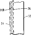
Fig. 2 a and Fig. 2 b are the comparisons of interference fringe pattern (20A, the 20B) example that produces in the emulsion to two photocopies.Fig. 2 a is the example of transmission (forward direction light beam) hologram, and Fig. 2 b is the example of reflection (back is to light beam) hologram.Produce these holograms, get its cross section then, with the difference in the interference figure of determining two kinds of methods.Know that the maximal value and the minimum value of waveform produced when interference figure was intersected by two light beams.In Fig. 2 a, emulsion 31 is positioned on the transparent base 33 (as glass).After with the exposure of forward direction Beam Technique, get the cross section of the plate after the development and at test under microscope.The light beam of object and the interference maximal value between the reference beams, the i.e. antinode of standing wave are carried in dark silver-colored particle or interference fringe 35 expressions in the emulsion 31.These interference fringes 35 are about 30-40 degree inclination with the photocopy surface normal, but in principle the angle of inclination in about 0-45 degree scope; The angle of inclination depend on to a great extent two between the light beam angle and the angle during their bump photocopy planes.This angle is basically parallel to the binary line of angle that will carry between object beam and the reference beams.The maximum angle that the forward direction Beam Technique is allowed is subjected to the restriction of the refractive index of emulsion 31, thereby is subjected to the critical angle restriction of total internal reflection, and this critical angle is about 40 degree for silver halide magenta-sensitive emulsion.In Fig. 2 B, photocopy is used for record reflection (back is to light beam) hologram, interference fringe 36 from the photocopy outside surface parallel error several years, and with light beam 23 that will carry object and reference beams 17 between the binary line of angle that forms substantially parallel.Two holograms of this of Fig. 2 a and Fig. 2 b all can be described as specific diffraction grating, but obviously their diffractive features has a great difference.Therefore, reflection (back to light beam) hologram can reconstruct in the incoherent light of reflection, and this character is that transmission (forward direction light beam) hologram is unexistent.
Fig. 3 has shown from the holographic Figure 46 reconstructed image of reflection (back is to light beam).Shine holographic Figure 46 with incoherent light 41 (daylight or incandescence) reflection, though what observer 43 saw is the image of reflection, but he still can see the 3-D view 45 of object 41 by " hologram window ", just as this object in holographic Figure 46 back.If emulsion does not shrink during plate is handled, this image has and is used for forming the color that hologram is used up.This method is at United States Patent (USP) 3,532, further description arranged in 406, and this patent documentation is included this paper in as a reference.
Another embodiment is transmission hologram and correlation technique.Another embodiment is the conventional surface relief method (surface reliefmethod) that adopts in the holography industry.A common scheme can vide infra.Fig. 4 shows a kind of arrangement, and it has formed transmission automobile figure or conventional surface relief hologram.Beam splitter 14 will be divided into two component 12A and 12B from the collimation coherent light 12 of laser instrument 10.Component 12A transmits through the mounting of telescope of camera lens 16 and 18 is arranged, to increase the xsect of light beam 12a.Its irradiating object 20.Object 20 reflections and scattering are from the light of illumination beam 12A.Wave front 22 is by the part of the light of object 20 reflections and scattering.The form of wave front 22 is relevant with object 20 on function.It incides photochromics 24 as on the photocopy.Wave front 22 contains the optical information relevant for object 20.Wherein have all required information of 3 dimensional drawing of seeing object 20.
The component 12B of collimation coherent light 12 is through a telescope that comprises camera lens 26 and 28, to increase its xsect and to provide previously selected shape for its waveform.With light beam 12B with chosen in advance waveform as reference.The waveform of light beam 12B should repeat to produce.For this reason, it is assembled at a P place.Reference beams 12B also is incident on the photochromics surface 24.Interference between the light of reference beams 12B and the wave front 22 forms the diffraction pattern with the unique relevant complexity of object 22 on photosensitivity surface 24.This pattern is the hologram of object 20.
Fig. 5 has shown and has been fit to be used for shining holographic Figure 54 that produces previously and the method that forms real orthoscopic image 58.Laser instrument 50 emission coherent lights 52.Camera lens 53 direct light 52 form pointolite by focus P at this place, give its predetermined waveform 55 then.Select the direction and the waveform 55 of illumination beam 52, so it has represented the time reversal (time reverse) of the reference beams 12B of the hologram that is used for forming Fig. 4.The time reversal light beam is a kind of like this light beam, and it has direction relevant with hologram image and waveform, so it looks it is that the point that original reference beams converged from having same waveform as comes out.Specifically, if reference beams 12B converges in photosurface 24 " p " point at a distance, then the time reversal of reference beams 12B is a kind of like this light beam, and it is relevant with hologram image 54, looks it is the P that sends with reference beams 12B same waveform as.Holographic Figure 54 adopts method shown in Figure 4 to obtain.When the time, reverse irradiates light 55 was incident on holographic Figure 54, the hologram image of holographic Figure 54 was diffracted into wave front 56 with a part of light 55.In diffraction process, wave front 56 has formed the waveform identical with wave front 22 by hologram image, but wave front 56 is to propagate with relative direction.Formed real image 58 by wave front 56.This true picture 58 is pseudoscopic images,, looks to have opposite fluctuating that is.Can write down it by placing photographic material in this space, image place.Have object 20 initial all optical information of in wave front 22, transmitting and incide on the photosurface 24 in the image 58.
Be recorded as the bar code of hologram image
Bar code of the present invention or other machine-readable code can enough routines and/or current scanning device readings.Herein, term " conventional sweep equipment " refers to introduce the scanning device of buying in market, and/or utilizes the at first scanning device for the time bar codes technique of Gong the commercialization of developing so far in nineteen fifty.Herein, term " current scanning device " refers in the front and back in January 1 calendar year 2001 in 2 years (embodiment), in the front and back 5 years in (another embodiment) and the front and back 10 years (another embodiment) sell the scanning device that uses for commercial by at least one manufacturer.Be explanation the application's purpose, word " at present " refers to the application's the applying date.
The invention provides the method and relevant element that machine readable code (as bar code) are added hologram, it also is very difficult that this method makes described code promptly enable to be duplicated by the outer any way of holography.In addition, according to the present invention, at the conventional bar code of the other placement of holographic bar code image.Result provided by the invention is the bar code (element) of enough conventional bar code scanners of a kind of energy (embodiment) and/or current bar code scanner (in another embodiment) scanning, but this bar code can not duplicate with the non-holographic mode such as the electrostatic reprography of routine.Bar code of the present invention can also be placed on position enough dark in the hologram, makes to be not easy identifiedly under general room light, and needs secondary light source to read.Bar code of the present invention is recorded as the full images of bar code in the photosensitive layer thickness (i.e. individual layer) of information recording carrier.More specifically, in the individual layer photosensitive layer that all bars of bar code and spacing are recorded in information recording carrier; Can not obtain bar code by the independent holographic bar shaped element of parallel placement side by side, the composite bar code with a plurality of holographic element is provided.Holographic bar code of the present invention can be independent (stand-alone) mark that does not have other image section, perhaps can be a part with many-sided mark of other parts such as design element.
The bar code of holographic recording of the present invention can comprise the bar code of any kind, and the characteristics of its non-limitative example are to have linearity (one dimension) bar code symbologies, bidimensional (2D) bar code symbologies and composite bar code symbolism.In one embodiment, the bar code of holographic recording has linearity (one dimension) bar code symbologies.
As noted, an embodiment of the invention are a kind of information recording carriers, and this medium comprises the bar code of the holographic recording with background in the photosensitive layer of exposure, and described bar code is made up of many parallel strips and many parallel distances; A plurality of parallel strips and a plurality of parallel distance comprise the fillet or the spacing of the width that is called the X yardstick; With the bar code with reconstruct wavelength X, wherein, the photosensitive layer of exposure is exposed to coherent actinic radiation with this photosensitive layer and obtains, and because the image interference is recorded this photosensitive layer, contains the photosensitive layer of the exposure of holographic recording bar code with generation;
Bar code wherein meets all the specified standards of at least a professional industrial organization relevant with bar codes technique that comprise UCC, AIM, ANSI, CEN and ISO that are selected from.
In a specific implementations, bar code is according to described in the preceding paragraph and meet all standards of UCC appointment.
In the embodiment, the X yardstick of bar code is in the 0.10-3.0mm scope.
In other embodiment, below information recording carrier recited above has to one of in the X yardstick explanation of the bar code of holographic recording:
A) the X yardstick is in 0.1mm (0.004 inch)-0.18mm (0.07 inch) scope.
B) the X yardstick is in 0.18mm (0.0071 inch)-0.33mm (0.013 inch) scope.
C) the X yardstick is in 0.33mm (0.013 inch)-0.635mm (0.025 inch) scope.
D) the X yardstick is in 0.635mm (0.025 inch)-1.0mm (0.0398 inch) scope.
E) the X yardstick is in 0.264mm (0.01 inch)-0.66mm (0.026 inch) scope.
In one embodiment, bar code can be read by the people and see.
In one embodiment, each bar of many parallel strips has the diffraction property identical with other all bars in the medium of the present invention.
In the medium of the present invention, the summation of a plurality of parallel strips and a plurality of parallel distances is equal to or greater than 10.In other different embodiment, one of numeral below the summation of a plurality of parallel strips and a plurality of parallel distances is equal to or greater than: 19,25,30,35,40,45 and 50.
In the medium of the present invention, the width of bar code is at least 2.5mm.In other different embodiments, bar code width is at least one of following width value: 4.5mm, 8mm, 12mm, 20mm, 25.4mm (1.0 inches), 38.1mm (1.5 inches), 50.8mm (2.0 inches), 63.5mm (2.5 inches) and 76.2mm (3.0 inches).
Do not limit the composition of the photosensitive layer of described medium especially.The non-limitative example that is suitable for the material of photosensitive layer is photopolymer, two look gelatin and photographic film (as silver hailde film).
In the embodiment, the feature of medium is to make the bar code of holographic recording have identical color with background.In another embodiment, the feature of medium is to make the bar code of holographic recording have different colors with background.In another embodiment, the feature of medium is to make the tone intensity of bar code of holographic recording greater than the tone intensity of background.
The present invention has some embodiments about the reconstruct wavelength X of the bar code of holographic recording.In one embodiment, the reconstruct wavelength X of the bar code of holographic recording is identical or basic identical with the reconstruct wavelength X of background.In another embodiment, the reconstruct wavelength X of the bar code of holographic recording is at the visible region of electromagnetic spectrum.In a specific implementations, at least a portion of the reconstruct wavelength X of the bar code of holographic recording is corresponding to ruddiness (in the visible region).In two other embodiments, the reconstruct wavelength X of the bar code of holographic recording is in one embodiment in the infrared light district of electromagnetic spectrum, in another embodiment at the ultraviolet region of electromagnetic spectrum.
In an embodiment of the invention, the medium recording that contains bar code is the body phase hologram, and this hologram can be reflection hologram or transmission hologram.In the another embodiment of the invention, the medium recording that contains bar code has the three-dimensional hologram of fluctuating for the surface.
All claim to a method that scan about the reconstructed image to the bar code of holographic recording of the present invention, those of the respective media claim that all parameters of these claim to a method, value, element etc. and scanning are provided are identical.A notable feature of recording method of the present invention is the full images that given bar code is recorded as the bar code in the individual layer photosensitive layer of information recording carrier.This is the advantage of this method just, promptly compares with art methods, and this method is simple, only needs the short time, and the bar code of higher correctness and precision can be provided.
About the method for above-mentioned manufacturing master hologram, in linear (one dimension) situation, model can be to comprise by the slide of the bar code of holographic recording.
Can adopt conventional holographic recording technology, constitute the hologram of information recording carrier of the present invention; These technology include but not limited to: two light beam transmission hologram methods and two beam reflection hologram methods.
Nomenclature
AIM-Automatic Identification Manufacturers, Inc., a tame U.S. trade association, general headquarters are positioned at Pittsburgh, PA.
ANSI-American National Standards Institute (ANSI) is responsible for voluntary barcode quality Study on standards.
The hole-be the physically opening of light path part in the device (as camera).The hole can be circle, rectangle, ellipse.
The character group and the code ANSI X3.4-1977 that are used for information exchange described in the ACII-American National code.
The ratio of aspect ratio-bar height and symbol lengths
The light color part of background-bar code symbol comprises the zone around the symbol of spacing, static zones and printing between the bar.
The dark color of bar-bar code symbol (low reflection) rectangle element.
Bar code-on width, change and represent the parallel line (bar) of data and the accurate arrangement of spacing.
One group of bar of bar code character-expression letter, numeral or out of Memory and spacing.
Bar code density-denotable character quantity in the linear unit of a measurement.
The size of bar height-measure from top to the bottom of bar (line).
The thickness of bar width-measure to another side from one side of bar (line).
Successfully read if two-way-bar code symbol can be independent of the direction of scanning, this bar code symbol is two-way.
Check digit-by the numeral of other digital computation in the bar code is used for checking data correctly to be constituted.
Codabar-Codabar is a kind of digital code with special character and four kinds of different beginning/final characters.
The high density code of a code 11-numeral.
Code 39 (39 code)-by the full word alphameric bar code that nine moduluses are formed, wherein three is wide.
Code 93-can be to the numeric-alphabetic bar code of the full word that the 128ASCII character is encoded.
The numeric-alphabetic bar code of full word that code 128--can encode to whole 128ASCII characters.
The number of characters of CPI-per inch.The character quantity that can in the linear unit of one inch measurement, represent.
Decoding-bar in the bar code symbol and spacing are converted into its corresponding data.
EAN-international commodity numbering system (being the European Article Number (EAN) system in the past).The international standard bar code that is used for the retail packaging for foodstuff.
EAN international organizations-based on Brussels, the EAN international organizations of Belguim is one and Uniform Code Council, a mechanism of the international member organization of the EAN of Inc. (UCC ) managed together EAN.UCC System and GlobalStandards Management Process.Referring to UniformCode Council, Inc. (UCC)
Single bar or spacing in element-a bar code symbol, or the part of a matrix notation.
Platform scanner device-fixed scanner (usually supermarket check out counters use) can be at any angle, be parallel to or near the plane that is parallel to the scanner window in read bar code system.
He-Ne (He-Ne) laser instrument-be used for one type laser instrument of bar code scanner.Can launch the relevant ruddiness of 633nm wavelength.
The people can read-be equivalent to the text of the coded message in the bar code symbol, be printed on usually the following of bar code symbol or above.
ISO (ISO (International Standards Organization))-this is a world rally from the national standard entity of 100 countries, is the process that promotes global standardsization from each its mission of national entity.More data can referring to
Http:// www.iso.ch
Laser scans device-a kind of barcode reading device that uses low energy laser to read bar code.
Mil-measuring unit, equal 1 inch 1/1000.
Nanometer-measuring unit is used for defining light wavelength, equals 10
-9Rice.
The spacing space of the blank of static zones-any mark is in before the beginning character of bar code, after final character.
Reflectance-from the amount of the light of the specific wavelength of test surfaces reflection or a series of wavelength and ratio from the amount of the light of baryta or the reflection of magnesium oxide reference material.
Resolution-can be distinguished or with the narrowest element size of certain device or method printing by the particular reader part.
Scanning reflection is than the record (0-100%) of the reflectance value of the single line bar mensuration of distribution-edge on the whole width of bar code symbol.
Scanner-reading bar code symbol also is converted into symbol the electric signal that can be understood by computer equipment.
From-verification-utilized the bar code or the symbol of checking algorithm, they can be applied independently in each character, prevent nd mistake.
Solid-state laser scanner-a kind of laser instrument of launching the light of 670nm and 780nm wavelength.
Lamination code-a kind of code, feature are that a bar code symbol has been divided several parts and one " stacked " on another, to improve the information density in this bar code symbol.
Standard-illustrate one group of rule, standard, indication and guidance how suitably using bar code.Usually send by a tissue such as UCC etc.
Beginning character-special bar code character is used for informing that scanner begins to read bar code symbol.Beginning character can find in the left side of bar code symbol usually.
Final character-special bar code character is used for informing that scanner stops to read bar code symbol.Final character can find on the right side of bar code symbol usually.
Symbol-by special symbol system required sign character and combination of features, comprise static zones, beginning and final character, data character and other auxiliary patterns, they form one together can scan entity completely.
One group of bar in the symbol of sign character-can a be decoded as individual unit and spacing.Independent numeral, letter, punctuate mark, control mark or a plurality of data character of its expression.
Symbolism-a kind of method of in a bar code, representing numeral or alphabetic character that is defined as; One type bar code.
Linear (one dimension) bar code symbolism-these are based on the parallel strip of a series of different in width and the bar code of spacing.They are to have used the prevailing bar code more than 25 years.
Bidimensional (2D) bar code symbologies-current use two types 2D bar code arranged, they are lamination code and matrix code.The feature of lamination code is that symbolic representation is arranged in their stacked formation in flat seam more.Example has code 49 and code 16K.Matrix code is made of the pattern that can be the sub-district (cell) of square, hexagon or circle.Relative position by these light colors and darker regions is encoded to data.
The composite bar code symbolism-this is the novel relatively symbolism of a class, wherein, and at close vicinity (fixing relative position) two symbols of printing mutually and comprise link data.Usually, one-component is a linear symbol, another or multirow symbol or matrix notation.
UCC -The Uniform Code Council, Inc -the be devoted to tissue of the research and the enforcement of measured global supply chain solution.These organization and administration U.P.C. and other retail standard.More information referring to
Www.uc.-council.org
Universial Product Code (U.P.C.)-this is the packing bar code symbol that is used for the kus kretail packaging for foodstuff.This code has carried out improving and being adopted by Europe, is used for the world sign of the packaging for foodstuff of EAN form.It also is a general term, refers to be coded in the UCC-12 data structure in UPC-A or the UPC-E bar code symbol.
The symbolism standard of the present series of USS (unified specification of symbols)-publish by AIM; Current (2005) comprise USS-I 2/5, USS-39, USS-93, USS-Codabar and USS-128.
Zone in the bar of space-(bar code symbol) is a highly reflective with respect to dark reverberation standard, and promptly the ink printing of bar or character is poor, and perhaps bite in the zone that will print of expection.The space can cause misreads or makes the reader can not read this symbol.
The specific width of the narrowest element (bar or spacing) in X yardstick-bar code symbol.
Embodiment
This embodiment has illustrated the holographic master of making bar code, uses this master to come the reproducing holographic bar code image subsequently.Also illustrated and used two kinds of different commercial scanners to come the scanning holography bar code.
Make the bar code hologram
At first be used in lines font code generator and produce linear (one dimension) bar code, (
Http:// www.idautomation.com/java/linearservlet.html) represents word " Dupont Holography " (Fig. 6 A), " on March 29th, 2004 " (Fig. 6 B), " 123456789101112 " (Fig. 6 D).The bar code that produces is shown in Fig. 6 A-6D.
Holographic imaging
The transparent positive that use is made by the bar code artwork carries out holographic imaging.This bar code generating is grown up to be a useful person and produce the digital picture of bar code on screen, this image is cliped and pasted into Photoshop, convert the TIF form to, use Agfa SelectSet 7000 Drum Imagesetter then, (Agfa, Regional Offices:Ridgefield Park, 100Challenger Road, Ridgefield Park, NJ 07660) optics transfers to film.The slide of making is placed on one 5 * 5 inches the ground glass diffuser.The ground glass diffuser carries out sandblast with 1/8 inch thick general window glass on its two sides and makes.The Cyclone Manufacturing BrownAluminum Oxide 150-180 grit sandblast of one side on this glass pane.Believe light or the direct reflection of using this sandblast diffuser that direct transmission can not take place.
The irradiation of H1 and exposure
Referring to Fig. 7, then, above-mentioned diffuser/slide assembly is linked to each other with the vibration isolation optical table 707 with stable metal support.In this model group piece installing, there is another stable support to be connected on the estrade.When exposing for the first time, this support 701 clamps the glass plate 702 (following H1) that has been coated with two look gelatin (DCG).Two look gelatin (DCG) are the hologram recording materials of using always, describe to some extent in its numerous documents, and for example referring to Rallison " control of DCG and non-silver-colored holographic material ", network address is as follows:
http://www.xmission.com/~ralcon/dcgprocess/p1.htm。
Before the DCG plate is in place, spatially filtered laser beam of slowly dispersing 703 and modelling are spent to being 45.These diffusion light beam irradiates DCG recording materials also cover mirror 708 below the slide.Mirror is with the back side of the laser beam direction diffuser bar code slide assembly of diffusion.Then, (CA), its power is 3 watts for Coherent Inc., Santa Clara, and light is emitted as 488nm, and floodlight shines this assembly with " CoherentSabre Argon ion laser " 706.The laser of this laser instrument at first passes through ground glass diffuser 705 from the ground glass face.This laser instrument is covered, (6 * 6 inches) DCG plate is placed on the about 1/4 inch place of slide and diffuser assembly top.Being used for the part of 488nm laser beam of this slide of back side illuminaton becomes with reference to light.
Enough exposures to DCG need about 50-70mJ usually.With Coherent Inc.Field Master power meter, the lip-deep power setting of DCG in the future is about 2500uw/cm, and the common time shutter is 20 seconds.
Then, close the diffusion laser beam.During the structure of the used model of this embodiment, making the DCG plate is about 54% indoor moistening 2 hours in humidity.The exposure of each batch DCG can be different with the moistening time.Therefore, need seek correct exposure and treatment conditions with the repetition test method of successive approximation.The repetition test method of successive approximation is that those skilled in the art are familiar with.5 * 5 inches glass plates that have been coated with near transparent DCG are fixed on 1/4 inch place, model surface top, hawk emblem, make its central authorities above model.Before exposure, provide 5 minutes time of repose, with dissipation model, optical devices, optical table and indoor heat and vibration.Then, open the preceding shutter of laser instrument and began exposure in 20 seconds.About 90% laser is by cated plate.The light of injecting meets from relative face with the object light of transmission, forms interference figure, is recorded in the DCG coating with the form of interference fringe.
Chemical treatment
After the exposure, will be placed on 45-60 second in the Kodak fixing bath for DCG (the two look gelatin) photographic plate of common hologram recording material.Then it is placed on immediately in the water of 80-120 (Fahrenheit temperature) about 4 seconds, in the water-bath of another 80-120 , placed about 4 seconds again.Then, put it in the bath of 80% isopropyl alcohol, 20% water of 130-140 about 4 seconds, in 100% alcohol of 2 continuous 130-140 is bathed, respectively placed 2 seconds again.Then, with the DCG plate of this exposure be immersed in 100% last alcohol bathe in the several seconds, be enough to make photographic plate from bathe, to take out lentamente during this period of time to promote uniform draining and drying.This moment, photographic plate can be observed, but film is a swelling, so the reconstruct of image is for next step step of exposure and Yan Taizao (green).With following dewatering color is transferred to original exposure wavelength 488nm.Plate was put back in the bath of 80% pure 20% water 4 seconds, and in 100% alcohol is bathed, cleaned then, and slowly take out.At this moment, the image among the H1 almost completely can not be recognized under general room light, because all image components are all from hologram surface (promptly more than 1/4 inch).
(same chemical treatment can be used to handle aforesaid H2DCG plate).
H1 transfers to H2
Referring to Fig. 8, use DCG anchor clamps, support and isolation platform 806.Record and handle a DCG hologram 803 after, carry out reverse conjugation irradiation with the counter-rotating of this hologram and to it, in the virtual peudoscopic image of bar code, place the unexposed plate 802 of the 2nd DCG.Three independently plate expose at a H1801 different distance place.Form the image that will be recorded in the H2 from the light of H1 reflection and scattering.Like this, in this surface about 1/8 inch locate, on this surface and in this lower face, locate to form three H2 that bar code image is arranged for about 1/8 inch.The 804th, LASER Light Source.The chemical treatment of H2 and top identical to H1.
Three H2 duplicate
Referring to Fig. 9, above-mentioned master hologram (H2) 901 is placed in the hologram replication device side by side, and (DuPontHolographics, Logan is in anchor clamps UT).Then, HRF 734 unexposed photopolymer duplicating film 903 (E.I.DuPont de Nemours﹠amp; Co., Inc., Wilmington DE) pushes/is laminated on its surface.With collimated laser light bundle 904 with the wavelength of 45 degree, 476nm and approximately the intensity of 1.25mw be mapped to last 40 second of master laminate of this film.Pick up duplicating film 905 from H2 then, moved to UV 2.6+ watt, the flood station (flood station) of 368nm 40 seconds by coiled material (by web).The rete that the UV of exposure is fixing is pressed onto toning film CTF146 (E.I.du Pont de Nemours; Co., Inc., Wilmington, DE) on, and with 3 meters/minute speed baking oven by 101 ℃ (Celsius temperatures).Pass through 150 ℃ scroll baking oven (scroll oven) then with 0.3 meter/minute speed.After from this baking oven, taking out film, its back layer is pressed on the two-sided black bonding agent.The transparent protectiveness top coat of single face is arranged in its front.Make the copying hologram of the bar code of each self-contained hologram record.
Scanning (in photopolymer film) holographic bar code
Laser diode bar code scanner with routine, Metrologic Instruments Inc.Voyager CG model MS9540, (West Deptford, NJ) PC with running word processor or spreadsheet program such as MicrosoftWord or Microsoft Excel is connected.Then, use this device scan to be recorded in the interior holographic bar code of holographic copy film.At all bar codes of Fig. 6 a-6d, except that Fig. 6 a, all read easily, and the bar code that translates can be presented in the window of word processor or electrical form.In this application Microsoft Word and Microsoft Excel are attempted, they can both well operate.
(Everett WA) also successfully reads the holographic bar code of Fig. 6 a-6d to image-type scanner (Intermec model Scanplus 1800 Sr).
The bar code of Fig. 6 a is readable in some trial (attempt), but not readable in other is attempted.The present also imprecise reason of misreading of knowing is still thought to be likely owing to be the tangible from left to right contrast variation of the bar code of the longest Fig. 6 a in bar code and in four kinds of (Fig. 6 a-6d) bar codes of test in this embodiment.Infer that observed contrast variation is because the inconsistent quality Control among the H2 causes.Give prominence on relative hologram surface in recording sheet or close this surface or the situation on the recording sheet surface to bar code image, the percent of misreading is lower.
Embodiment 2
Make the bar code hologram
At first be used in lines font code generator and produce first linearity (one dimension) bar code, (
Http:// www.idautomation.com/java/linearservlet.html)Represent word " Dupont holography "
(Fig. 6 a), " on March 29th, 2004 " (Fig. 6 b), " 123456789101112 " (Fig. 6 d).These bar codes that produce are shown in Fig. 6 a-6d.Then, use conventional office laser printer with these bar code printings on paper.These bar codes that produce make and are shown in Fig. 6 a-6d.
Then, making 1/8 * 4 * 5 inches DCG (two look gelatin) plate is about 54% indoor moistening 2 hours in humidity.The exposure of each batch DCG can be different with the moistening time.Therefore, need seek correct exposure and treatment conditions with the repetition test method of successive approximation.The repetition test method of successive approximation is that those skilled in the art are familiar with.Two look gelatin (DCG) are the hologram recording materials of using always, describe to some extent in its numerous documents, and for example referring to Rallison " control of DCG and non-silver-colored holographic material ", network address is as follows:
Http:// www.xmission.com/~ralcon/dcgprocess/p1.htm
Referring to Figure 10.The paper that will print bar code 90 with common transparent double sticky tape is connected with the uncoated face of DCG plate 91.Use expansion 3 watts of 532nm " " (CoherentInc., Santa Clara CA) carry out holographic exposure to laser beam 92 to Cohernet Verdi, and this laser beam at first becomes reference beams by photosensitive DCG plate; Then, keep on about 90% bar code that is radiated on the paper that is positioned at glass 93 back sides of light.
Light from the white portion of paper is reflected back to the DCG plate, through exposure in 30 seconds with suitably form interference figure after the chemical treatment.As shown in figure 10, the DCG plate is the angular orientation of 45 degree with relative surface level when exposure, and laser beam is level; Therefore, during holographic exposure, the angle between this laser beam and the DCG plate is 135 degree.After the processing, this pattern becomes the diffraction interference striped, and at the about 1/8 inch holographic copy figure that locates to produce bar code of DCG lower face, for orange red, the reconstruct wavelength is about 610nm during reconstruct.This is the method for a kind of known manufacturing described in U.S. Patent application US20030016408A1 " step " or " Densiyuk " hologram.
Chemical treatment
After the exposure, will be placed on 45-60 second in the Kodak fixing bath for DCG (the two look gelatin) plate of common hologram recording material.Then it is placed on immediately in the water of 80-120 (Fahrenheit temperature) about 4 seconds, in the water-bath of another 80-120 , placed about 4 seconds again.Then, put it in the bath of 80% isopropyl alcohol, 20% water of 130-140 about 4 seconds, in 100% alcohol of 2 continuous 130-140 is bathed, respectively placed 2 seconds again.Then, with the DCG plate of this exposure be immersed in 100% last alcohol bathe in the several seconds, be enough to make plate from bathe, to take out lentamente during this period of time to promote uniform draining and drying.Because exposure wavelength is the relatively long wavelength of 532nm, the reconstructed image of swelling comprises the reflection to red light of enough degree, the feasible bar code that can detect and read holographic recording under red laser with conventional laser bar code scanner (operating usually).In this stage, hologram is H1.
Scanning (in two look gelatin) holographic bar code
Laser diode bar code scanner with routine, Metrologic Instruments Inc.Voyager CG model MS9540, (West Deptford, NJ) PC with operation word processor or spreadsheet program such as MicrosoftWord or Microsoft Excel is connected.Then, use this device scan to be recorded in the interior holographic bar code of DCG plate.All bar codes at Fig. 6 a-6d are all read easily, and the bar code that translates can be presented in the window of word processor or electrical form.In this application Microsoft Word and Microsoft Excel are attempted, they can both well operate.But the reading problem identical with embodiment 1 appears in Fig. 6 a.
Image-type scanner (Intermec model Scanplus 1800 Sr) (Everett, WA) the also holographic bar code of Fig. 6 a-6d of playback record in two look gelatin successfully.
Embodiment 3 (estimating example)
In this embodiment, adopt identical with embodiment 1 process and method that the bar code of holographic recording is recorded in the film of photopolymer, difference is that the code of record is a Data Matrix code, alternative bar code.Other details of Data Matrix code can be from RVSI Acuity Cimatrix Co., Nashua, and NH obtains.This holographic code is estimated and can successfully be read/scan with scanner or the typical 2 d code reader of embodiment 1.
Embodiment 4 (estimating example)
In this embodiment, adopt identical with embodiment 1 process and method that the bar code of holographic recording is recorded in the film of photopolymer, difference is that the code of record is code 49 (two-dimensional bar)), instead of linear (one dimension) bar code.Obtain the code 49 of holographic recording.This holographic code is estimated and can successfully be read/scan with scanner and the commercial scanner of any routine of embodiment 1.
Embodiment 5 (estimating example)
In this embodiment, adopt identical with embodiment 1 process and method that the bar code of holographic recording is recorded in the film of photopolymer, difference is that the code of record is the composite bar code with linear symbol and matrix notation, instead of linear (one dimension) bar code.Obtain the composite bar code of holographic recording.This holographic code is estimated and can successfully be read/scan with the scanner that scanner and any conventional commerce of embodiment 1 can be read composite bar code.
Claims (10)
1. information recording carrier, this recording medium comprise the bar code of holographic recording and the background of finding in the photosensitive layer of individual layer exposure, described bar code is made up of many parallel strips and spacing;
Described bar code has the reconstruct wavelength X, wherein, the photosensitive layer of exposure is exposed to coherent actinic radiation with this photosensitive layer and obtains, and because the image interference is recorded this photosensitive layer, generation contains the photosensitive layer of exposure of the bar code of holographic recording, and described bar code meets all the specified standards of at least a professional industrial organization relevant with bar codes technique that are selected from UCC, AIM, ANSI, CEN and ISO.
2. information recording carrier, this recording medium comprise the bar code of holographic recording and the background of finding in the photosensitive layer of individual layer exposure, described bar code is made up of many parallel strips and spacing;
Described bar code has the reconstruct wavelength X, and wherein, the photosensitive layer of exposure is exposed to coherent actinic radiation with this photosensitive layer and obtains, and because the image interference is recorded this photosensitive layer, produces the photosensitive layer of the exposure of the bar code that contains holographic recording,
Described bar code can scan with conventional sweep equipment.
3. information recording carrier as claimed in claim 2 is characterized in that, the X yardstick of described bar code is at least 0.0067 inch, i.e. 6.7 mils or 0.17mm.
4. information recording carrier as claimed in claim 2 is characterized in that, the X yardstick of described bar code is at 0.10mm-3.0mm, i.e. 0.004-0.1182 inch scope.
5. information recording carrier as claimed in claim 2 is characterized in that, the many parallel strips of described bar code and the summation quantity of parallel distance are equal to or greater than 10.
6. information recording carrier as claimed in claim 2 is characterized in that, the reconstruct wavelength X of the bar code of described holographic recording is identical or basic identical with the reconstruct wavelength X of background.
7. the reconstructed image to the holographic recording bar code that comprises in the holographic recording medium carries out method for scanning, and this method comprises following step:
Information recording carrier is provided, this recording medium comprises the bar code of holographic recording and the background of finding in the photosensitive layer of individual layer exposure, described bar code is made up of many parallel strips and spacing, described bar code has the reconstruct wavelength X, wherein, the photosensitive layer of exposure is exposed to coherent actinic radiation with this photosensitive layer and obtains, and because the image interference is recorded this photosensitive layer, generation contains the photosensitive layer of exposure of the bar code of holographic recording, and described bar code meets and is selected from UCC, AIM, ANSI, all specified standards of at least a professional industrial organization relevant of CEN and ISO with bar codes technique;
Use the scanner scans bar code, this bar code is read by described scanner.
8. the reconstructed image to the holographic recording bar code that comprises in the holographic recording medium carries out method for scanning, and this method comprises following step:
Information recording carrier is provided, this recording medium comprises the bar code of holographic recording and the background of finding in the photosensitive layer of individual layer exposure, described bar code is made up of many parallel strips and spacing, described bar code has the reconstruct wavelength X, wherein, the photosensitive layer of exposure is that this photosensitive layer that will have a surface is exposed to the coherent actinic radiation acquisition, and because image is recorded this photosensitive layer with interfering, contain the photosensitive layer of exposure of the bar code of holographic recording with generation, described bar code can scan with conventional sweep equipment;
Use the scanner scans bar code, this bar code is read by described scanner.
9. method as claimed in claim 8 is characterized in that, the image of the bar code of described holographic recording is recorded on the surface of photosensitive layer, the surface or under the surface.
10. a manufacturing comprises the method for master hologram of the bar code of at least one holographic recording, and this method comprises following step:
G. obtaining will be at the model of all elements in the master hologram, and described element comprises at least one bar code;
First photosensitive film that h. will be suitable for holographic recording places between this model and the coherent source, and described first photosensitive film has a surface;
I. first photosensitive film uses the light from coherent source to expose, and with first hologram image (H1) of record physical model, this first hologram image comprises the bar code of at least one holographic recording of first hologram image;
J. first hologram image is reversed with respect to coherent source, and remove this physical model;
Second photosensitive film that k. will be suitable for holographic recording places between the coherent source and first hologram image, and second photosensitive film is near first hologram image; With
L. second photosensitive film uses the light from coherent source to expose, and to write down second hologram image (H2) as the master hologram, this second hologram image comprises the bar code as at least one holographic recording of second hologram of master hologram.
Applications Claiming Priority (3)
| Application Number | Priority Date | Filing Date | Title |
|---|---|---|---|
| US70955105P | 2005-08-19 | 2005-08-19 | |
| US60/709,551 | 2005-08-19 | ||
| US60/710,838 | 2005-08-24 |
Publications (1)
| Publication Number | Publication Date |
|---|---|
| CN1916930A true CN1916930A (en) | 2007-02-21 |
Family
ID=37737924
Family Applications (1)
| Application Number | Title | Priority Date | Filing Date |
|---|---|---|---|
| CN 200610121524 Pending CN1916930A (en) | 2005-08-19 | 2006-08-17 | Information-recorded medium containing a holographically-recorded bar code and associated methods |
Country Status (1)
| Country | Link |
|---|---|
| CN (1) | CN1916930A (en) |
Cited By (2)
| Publication number | Priority date | Publication date | Assignee | Title |
|---|---|---|---|---|
| CN104094277A (en) * | 2011-12-23 | 2014-10-08 | 可耐福石膏两合公司 | Method and system for checking the presence or the legibility of product information |
| CN110462489A (en) * | 2017-03-27 | 2019-11-15 | 索尼公司 | Image display device and image display element |
-
2006
- 2006-08-17 CN CN 200610121524 patent/CN1916930A/en active Pending
Cited By (3)
| Publication number | Priority date | Publication date | Assignee | Title |
|---|---|---|---|---|
| CN104094277A (en) * | 2011-12-23 | 2014-10-08 | 可耐福石膏两合公司 | Method and system for checking the presence or the legibility of product information |
| US10410020B2 (en) | 2011-12-23 | 2019-09-10 | Knauf Gips Kg | Method and system for checking the presence and/or readability of an item of product information |
| CN110462489A (en) * | 2017-03-27 | 2019-11-15 | 索尼公司 | Image display device and image display element |
Similar Documents
| Publication | Publication Date | Title |
|---|---|---|
| JP3952034B2 (en) | Hologram recording method, hologram recording apparatus, hologram reproducing method, hologram reproducing apparatus, and information holding body | |
| EP0077925B1 (en) | Method for making holographic optical elements with high diffraction efficiencies | |
| EP1810221B1 (en) | Diffractive imaging system for acquiring an image of skin topology and corresponding method | |
| Goodman | Film-grain noise in wavefront-reconstruction imaging | |
| RU2380750C2 (en) | Methods and devices for creation of printing products with possibility of their identification and their subsequent verification | |
| CN107425019B (en) | Imaging and decoding apparatus with quantum dot imager | |
| JP5622710B2 (en) | Holographic data recording medium | |
| US20120318860A1 (en) | Authentication label applied over barcode with barcode still being readable | |
| JP2004530933A (en) | Holographic data storage medium | |
| US6824929B2 (en) | Method and element for holographic replication | |
| EP1564605A2 (en) | Security device using a hologram reconstructing a deep image | |
| CN1916930A (en) | Information-recorded medium containing a holographically-recorded bar code and associated methods | |
| EP1851680A2 (en) | System and method for optically imaging objects on a detection device by means of a pinhole aperture | |
| EP1755007A2 (en) | Information-recorded medium containing a holographically-recorded bar code and associated methods | |
| JPS6037475B2 (en) | How confidential information is handled | |
| Wang et al. | Holography with surface-plasmon-coupled waveguide modes | |
| CA2621003A1 (en) | Storage medium for confidential information | |
| HK1098227A (en) | Information-recorded medium containing a holographically-recorded bar code and associated methods | |
| Landry et al. | Measurement of diffraction efficiency, SNR, and resolution of single-and multiple-exposure amplitude and bleached holograms | |
| EP1785782A2 (en) | Security hologram and associated methods of use and of making | |
| Berg | The photographic emulsion layer as a three-dimensional recording medium | |
| Pandey et al. | Technique for characterization of dimensional changes in slanted holographic gratings by monitoring the angular selectivity profile | |
| JP3433643B2 (en) | Image reading device and scanner | |
| US7599514B2 (en) | Optical information reading device | |
| CN100389427C (en) | Method and device for improving anti-damage of word and image in machine readable tag |
Legal Events
| Date | Code | Title | Description |
|---|---|---|---|
| C06 | Publication | ||
| PB01 | Publication | ||
| REG | Reference to a national code |
Ref country code: HK Ref legal event code: DE Ref document number: 1098227 Country of ref document: HK |
|
| C10 | Entry into substantive examination | ||
| SE01 | Entry into force of request for substantive examination | ||
| C02 | Deemed withdrawal of patent application after publication (patent law 2001) | ||
| WD01 | Invention patent application deemed withdrawn after publication |
Open date: 20070221 |
|
| REG | Reference to a national code |
Ref country code: HK Ref legal event code: WD Ref document number: 1098227 Country of ref document: HK |