CN1894999B - Piezoelectric electro-acoustic converter - Google Patents
Piezoelectric electro-acoustic converter Download PDFInfo
- Publication number
- CN1894999B CN1894999B CN200480037278.0A CN200480037278A CN1894999B CN 1894999 B CN1894999 B CN 1894999B CN 200480037278 A CN200480037278 A CN 200480037278A CN 1894999 B CN1894999 B CN 1894999B
- Authority
- CN
- China
- Prior art keywords
- adhesive
- piezoelectric
- elastic adhesive
- vibrating diaphragm
- diaphragm
- Prior art date
- Legal status (The legal status is an assumption and is not a legal conclusion. Google has not performed a legal analysis and makes no representation as to the accuracy of the status listed.)
- Expired - Lifetime
Links
Images


Classifications
-
- H—ELECTRICITY
- H04—ELECTRIC COMMUNICATION TECHNIQUE
- H04R—LOUDSPEAKERS, MICROPHONES, GRAMOPHONE PICK-UPS OR LIKE ACOUSTIC ELECTROMECHANICAL TRANSDUCERS; DEAF-AID SETS; PUBLIC ADDRESS SYSTEMS
- H04R17/00—Piezoelectric transducers; Electrostrictive transducers
Landscapes
- Physics & Mathematics (AREA)
- Engineering & Computer Science (AREA)
- Acoustics & Sound (AREA)
- Signal Processing (AREA)
- Piezo-Electric Transducers For Audible Bands (AREA)
Abstract
为避免因比如下落冲击等引起压电振动膜片的过度弯曲,以防止导电粘合剂的破裂。压电电声变换器包括:矩形压电振动膜片(1);外壳(10),其内部具有支架(10f),用以支撑压电振动膜片(1)底面的四角;固定在外壳(10)上的接线端(11,12),每个接线端都有暴露于支架附近的内连接部分;第一弹性粘合剂(13)涂敷于压电振动膜片四周与接线端之间;导电粘合剂(14)涂敷于压电振动膜片的电极与接线端之间,位于第一弹性粘合剂顶面上;第二弹性粘合剂(15)填充并密封压电振动膜片四周与外壳内部之间的间隙;防过振幅接收器(10p)一体地设置在外壳的底壁上,用于将压电振动膜片的振动幅度限制在预定范围。防过振幅接收器定位于比支架10f更靠近压电振动膜片的中心。
To avoid excessive bending of the piezoelectric vibrating diaphragm due to, for example, a drop impact, etc., to prevent cracking of the conductive adhesive. The piezoelectric electroacoustic transducer comprises: a rectangular piezoelectric vibrating diaphragm (1); a housing (10), which has a bracket (10f) inside to support the four corners of the bottom surface of the piezoelectric vibrating diaphragm (1); fixed on the housing ( 10) on the terminals (11, 12), each terminal has an inner connection part exposed near the bracket; the first elastic adhesive (13) is coated around the piezoelectric vibrating diaphragm and between the terminals ; The conductive adhesive (14) is applied between the electrode and the terminal of the piezoelectric vibrating diaphragm, and is located on the top surface of the first elastic adhesive; the second elastic adhesive (15) fills and seals the piezoelectric vibration The gap between the periphery of the diaphragm and the inside of the housing; the anti-over-amplitude receiver (10p) is integrally arranged on the bottom wall of the housing, and is used to limit the vibration amplitude of the piezoelectric vibrating diaphragm to a predetermined range. The anti-over-amplitude receiver is positioned closer to the center of the piezoelectric vibrating diaphragm than the bracket 10f.
Description
技术领域technical field
本发明涉及一种压电电声变换器,如压电发声器、压电接收器和压电扬声器等。The invention relates to a piezoelectric electroacoustic transducer, such as a piezoelectric sounder, a piezoelectric receiver and a piezoelectric speaker.
背景技术Background technique
用于发出报警声音或操作声音的压电电声变换器已被广泛地用在电子设备、消费产品和蜂窝电话中,如作为压电发声器或压电接收器。已经提出过包含矩形振动膜片的压电电声变换器,以实现更高的生产效率、更高的电声转换效率和尺寸缩减。Piezoelectric electroacoustic transducers for emitting alarm sounds or operating sounds have been widely used in electronic equipment, consumer products, and cellular phones, such as piezoelectric sounders or piezoelectric receivers. Piezoelectric electroacoustic transducers including rectangular vibrating diaphragms have been proposed to achieve higher production efficiency, higher electroacoustic conversion efficiency, and size reduction.
对于较低的频率,目前已经采用了厚度在几十到几百微米数量级的超薄振动膜片。支撑振动膜片的结构对这种薄振动膜片的频率特性具有极大的影响。For lower frequencies, ultra-thin diaphragms with a thickness on the order of tens to hundreds of microns have been used. The structure supporting the diaphragm has a great influence on the frequency characteristics of such a thin diaphragm.
例如,如果以热固性导电粘合剂使振动膜片直接与固定于外壳上的接线端相连,则由于导电粘合剂的固化和收缩所引起的应力使振动膜片拉紧。这种拉紧会导致振动膜片的频率特性的变化。而且,由于固化的导电粘合剂具有相对较高的杨氏模量,所以固化的导电粘合剂对振动膜片的振动造成不利的影响,或者相反地会因振动膜片的振动,而使导电粘合剂产生破裂。For example, if the vibrating diaphragm is directly connected to terminals fixed to the housing with a thermosetting conductive adhesive, the vibrating diaphragm is strained by the stress caused by the curing and shrinkage of the conductive adhesive. This tension causes changes in the frequency characteristics of the vibrating diaphragm. Also, since the cured conductive adhesive has a relatively high Young's modulus, the cured conductive adhesive adversely affects the vibration of the vibrating diaphragm, or conversely causes the vibrating diaphragm to vibrate. Conductive adhesive cracks.
专利文献1提出一种压电电声变换器,它包括:压电振动膜片;外壳,它的内部具有支架,用以在其两侧或四周支撑压电振动膜片的底面;接线端,具有暴露在支架附近的内连接部分;第一弹性粘合剂,涂敷在压电振动膜片的四周与接线端的内连接部分之间,以便将压电振动膜片固定到外壳上;导电粘合剂,涂敷在压电振动膜片的电极与接线端的内连接部分之间,位于第一弹性粘合剂的顶面上,以便使压电振动膜片的电极与接线端的内连接部分电连接;以及第二弹性粘合剂,用于密封压电振动膜片的四周与外壳的内部之间的间隙。例如,所使用的第一弹性粘合剂是氨基甲酸酯粘合剂。所使用的第二弹性粘合剂是杨氏模量比第一弹性粘合剂的杨氏模量小的材料,如有机硅粘合剂。
在这种情况下,比如,所述第一弹性粘合剂的弹性防止因导电粘合剂的固化和收缩所引起的应力而导致振动膜片的频率特性的变化,以及固化的弹性粘合剂的破裂。但是,支架可能会约束压电振动膜片,并阻碍其弯曲振动,因为支架在两侧或四周支撑压电振动膜片。In this case, for example, the elasticity of the first elastic adhesive prevents changes in the frequency characteristics of the vibrating diaphragm due to stress caused by curing and shrinkage of the conductive adhesive, and the cured elastic adhesive of rupture. However, the bracket may constrain the piezoelectric diaphragm and impede its flexural vibration, since the bracket supports the piezoelectric diaphragm on both sides or all around.
专利文献2公开一种压电电声变换器,它包括:压电振动膜片;外壳,具有在四个角支撑压电振动膜片的底面的支架;第一弹性粘合剂,涂敷在压电振动膜片与支架附近的接线端之间;以及导电粘合剂,涂敷在第一弹性粘合剂上,以便将压电振动膜片与接线端电连接。
在这种情况下,支架具有较小的支撑面积,因为其仅支撑压电振动膜片的角。这种电声变换器可以产生更高的声压,而不会约束振动膜片。In this case, the bracket has a smaller support area because it only supports the corners of the piezoelectric diaphragm. This electro-acoustic transducer can generate higher sound pressure without constraining the vibrating diaphragm.
因此,具有用于在其角部支撑压电振动膜片的支架的压电电声变换器可以产生更高的声压。对于进一步的尺寸缩减和更高的声压而言,需要更小的振动膜片支撑面积,而对于更低的频率,需要更小的振动膜片厚度。但是,更薄的振动膜片更容易弯曲,而如果支撑面积较小,例如,下落冲击可能会引起振动膜片的较大弯曲。振动膜片较大的弯曲在导电粘合剂附近引起较大的振动幅度,而过度的应力相应地作用于导电粘合剂。过度的应力可能会不利地引起导电粘合剂的破裂,因此降低了产品的连接可靠性。Therefore, a piezoelectric electroacoustic transducer having a bracket for supporting the piezoelectric vibrating diaphragm at its corners can generate a higher sound pressure. For further size reduction and higher sound pressure, a smaller diaphragm support area is required, while for lower frequencies, a smaller diaphragm thickness is required. However, thinner diaphragms are more prone to flexing, and if the support area is small, for example, a drop impact may cause a large deflection of the diaphragm. The larger deflection of the vibrating diaphragm induces larger vibration amplitudes in the vicinity of the conductive adhesive, and excessive stress acts on the conductive adhesive accordingly. Excessive stress may disadvantageously cause cracking of the conductive adhesive, thus reducing connection reliability of the product.
图14示出现有技术中用于支撑压电振动膜片的支架的截面图。Fig. 14 shows a cross-sectional view of a bracket used to support a piezoelectric vibrating membrane in the prior art.
在图14(a)中,支架32支撑振动膜片30的角部。弹性粘合剂34涂敷在振动膜片30与插入在外壳33中的接线端33之间。例如,所使用的弹性粘合剂34是氨基甲酸酯粘合剂。导电粘合剂35涂敷在弹性粘合剂34上,以使振动膜片30的电极与接线端33电连接。In FIG. 14( a ),
在这种支架结构中,例如,如果下落冲击对振动膜片30加给向下的加速度G,则振动膜片30以支架32作为支点向下弯曲,如图14(b)所示。于是,向下弯曲对导电粘合剂35施加张应力,并引起破裂35。In this bracket structure, for example, if a drop impact applies downward acceleration G to the
专利文献3公开了一种压电发声器,包括单片晶片(unimorph)压电振动膜片和具有从其底面开始延伸的防弯曲柱的外壳。例如,如果下落冲击施加了超过振动膜片的弯曲强度的外力,防弯曲柱限制压电振动膜片的弯曲。但是,防弯曲柱倾向于防止压电振动膜片自身的破裂以及陶瓷片与金属片之间的分层,并未考虑上述导电粘合剂的破裂。Patent Document 3 discloses a piezoelectric sounder including a unimorph piezoelectric vibrating diaphragm and a case having bending-preventing posts extending from the bottom surface thereof. For example, if a drop impact applies an external force exceeding the bending strength of the vibrating diaphragm, the anti-bending post restricts the bending of the piezoelectric vibrating diaphragm. However, the anti-bending post tends to prevent cracking of the piezoelectric vibrating diaphragm itself and delamination between the ceramic sheet and the metal sheet, and does not take into account the above-mentioned cracking of the conductive adhesive.
专利文献1:日本未审专利申请公开No.2003-9286Patent Document 1: Japanese Unexamined Patent Application Publication No. 2003-9286
专利文献2:日本未审专利申请公开No.2003-23696Patent Document 2: Japanese Unexamined Patent Application Publication No. 2003-23696
专利文献3:日本未审实用新型注册申请公开No.7-16500Patent Document 3: Japanese Unexamined Utility Model Registration Application Publication No. 7-16500
发明内容Contents of the invention
本发明的目的在于提供一种压电电声变换器,能够避免由于如下落冲击等而引起的压电振动膜片过度弯曲,以防止导电粘合剂的破裂。An object of the present invention is to provide a piezoelectric electroacoustic transducer capable of avoiding excessive bending of a piezoelectric vibrating diaphragm caused by, for example, a drop impact, to prevent cracking of a conductive adhesive.
为实现上述目的,按照本发明的第一方案,提出一种压电电声变换器,它包括:矩形压电振动膜片,跨过它的电极向它提供周期信号,从而沿厚度方向弯曲和振动;外壳,它的内部具有支架,用于支撑压电振动膜片的底面的四个角;固定在外壳上的接线端,每个接线端均具有暴露在支架附近的内连接部分;第一弹性粘合剂,涂敷在压电振动膜片的四周与接线端的内连接部分之间,用于将压电振动膜片紧固在外壳上;导电粘合剂,涂敷在压电振动膜片的电极与接线端的内连接部分之间,位于第一弹性粘合剂的顶面上,用于使压电振动膜片的电极与接线端的内连接部分电连接;第二弹性粘合剂,填充并密封压电振动膜片的四周与外壳的内部之间的间隙;以及防过振幅(overamplitude)接收器,位于外壳上,用于将压电振动膜片的振动幅度限制在预定的范围。防过振幅接收器定位于比支架更靠近压电振动膜片的中心。第二弹性粘合剂填充压电振动膜片的底面与防过振幅接收器的顶面之间的间隙。In order to achieve the above object, according to the first aspect of the present invention, a piezoelectric electroacoustic transducer is proposed, which includes: a rectangular piezoelectric vibrating diaphragm, to which a periodic signal is provided across its electrodes, thereby bending and Vibration; a casing having brackets inside for supporting the four corners of the bottom surface of the piezoelectric vibrating diaphragm; terminals fixed on the casing, each of which has an inner connecting portion exposed near the bracket; the first Elastic adhesive, coated between the surrounding part of the piezoelectric vibrating diaphragm and the internal connection part of the terminal, used to fasten the piezoelectric vibrating diaphragm to the shell; conductive adhesive, coated on the piezoelectric vibrating film Between the electrodes of the sheet and the internal connection part of the terminal, it is located on the top surface of the first elastic adhesive, which is used to electrically connect the electrode of the piezoelectric vibrating diaphragm to the internal connection part of the terminal; the second elastic adhesive, filling and sealing the gap between the periphery of the piezoelectric vibrating membrane and the inside of the housing; and an overamplitude anti-overamplitude receiver located on the housing for limiting the vibration amplitude of the piezoelectric vibrating membrane to a predetermined range. The anti-over-amplitude receiver is positioned closer to the center of the piezoelectric diaphragm than the bracket. The second elastic adhesive fills the gap between the bottom surface of the piezoelectric vibrating diaphragm and the top surface of the over-amplitude preventing receiver.
将支架设置在外壳的内部,以支撑并保持压电振动膜片底面的四角,而不过度地约束振动膜片。由于支架仅支撑压电振动膜片的角部,压电振动膜片可以较为容易发生位移,以产生更高的声压。但是,下落冲击能够使压电振动膜片产生较大的弯曲,并因而使连接压电振动膜片的电极与接线端的内连接部分的导电粘合剂破裂。Standoffs are provided inside the housing to support and hold the corners of the bottom surface of the piezoelectric diaphragm without unduly constraining the diaphragm. Since the bracket only supports the corners of the piezoelectric vibrating diaphragm, the piezoelectric vibrating diaphragm can be easily displaced to generate higher sound pressure. However, the drop impact can cause a large bending of the piezoelectric vibrating membrane, and thus break the conductive adhesive connecting the electrodes of the piezoelectric vibrating membrane to the internal connection portions of the terminals.
在本发明中,将防过振幅接收器设置成比支架更靠近压电振动膜片的中心,以将压电振动膜片的振动幅度限制在预定的范围。此外,第二弹性粘合剂填充压电振动膜片的底面与防过振幅接收器的顶面之间的间隙,以便在振动膜片弯曲时,对压电振动膜片的底面进行软支撑。由此,第二弹性粘合剂能够消除对压电振动膜片的冲击,解决比如破裂等问题。In the present invention, the anti-over-amplitude receiver is arranged closer to the center of the piezoelectric vibrating membrane than the bracket, so as to limit the vibration amplitude of the piezoelectric vibrating membrane to a predetermined range. In addition, the second elastic adhesive fills the gap between the bottom surface of the piezoelectric vibrating membrane and the top surface of the over-amplitude preventing receiver, so as to softly support the bottom surface of the piezoelectric vibrating membrane when the vibrating membrane is bent. Thus, the second elastic adhesive can eliminate the impact on the piezoelectric vibrating membrane, solving problems such as cracking.
按照第二种方案,所述压电振动膜片的底面与防过振幅接收器的顶面之间的距离优选为0.01到0.2mm。According to the second solution, the distance between the bottom surface of the piezoelectric vibrating diaphragm and the top surface of the over-amplitude preventing receiver is preferably 0.01 to 0.2 mm.
如果距离超过0.2mm,则电声变换器不能防止压电振动膜片的过振幅振动,于是,必然会使导电粘合剂更容易破裂。如果距离在0.01mm以下,则第二弹性粘合剂在压电振动膜片与防过振幅接收器之间具有较小的厚度。结果,防过振幅接收器倾向于阻碍压电振动膜片的位移,从而减小声压。If the distance exceeds 0.2mm, the electroacoustic transducer cannot prevent the excessive amplitude vibration of the piezoelectric vibrating diaphragm, and thus, the conductive adhesive must be more easily broken. If the distance is below 0.01 mm, the second elastic adhesive has a small thickness between the piezoelectric vibrating diaphragm and the over-amplitude preventing receiver. As a result, the anti-overamplitude receiver tends to hinder the displacement of the piezoelectric vibrating diaphragm, thereby reducing the sound pressure.
按照第三种方案,最好使第一弹性粘合剂固化后具有500×106Pa或更小的杨氏模量,以及使第二弹性粘合剂固化后具有30×106Pa或更小的杨氏模量。According to the third method, it is preferable that the first elastic adhesive has a Young's modulus of 500×10 6 Pa or less after curing, and that the second elastic adhesive has a Young's modulus of 30×10 6 Pa or less after curing. Small Young's modulus.
也就是说,第一和第二弹性粘合剂固化后具有不致对振动膜片的位移造成严重影响的杨氏模量。如果第一和第二弹性粘合剂固化后分别具有500×106Pa或更小和30×106Pa或更小的杨氏模量,则振动膜片的位移至少是其最大位移的90%。因此,第一和第二弹性粘合剂不会对振动膜片的位移造成严重影响。That is to say, the cured first and second elastic adhesives have Young's modulus which will not seriously affect the displacement of the vibrating diaphragm. If the first and second elastic adhesives have respectively cured Young's modulus of 500×10 6 Pa or less and 30×10 6 Pa or less, the displacement of the diaphragm is at least 90 of its maximum displacement %. Therefore, the first and second elastic adhesives do not seriously affect the displacement of the vibrating diaphragm.
将第二弹性粘合剂的杨氏模量限制为较窄的可接受范围,因为压电振动膜片的动作更容易受到第二弹性粘合剂的杨氏模量的影响。将第二弹性粘合剂涂敷在压电振动膜片的四周,而将第一弹性粘合剂局部地涂敷在压电振动膜片上,即仅在其角部周围。The Young's modulus of the second elastic adhesive is limited to a narrow acceptable range because the behavior of the piezoelectric vibrating diaphragm is more easily affected by the Young's modulus of the second elastic adhesive. The second elastic adhesive is applied on the periphery of the piezoelectric vibrating membrane, and the first elastic adhesive is partially applied on the piezoelectric vibrating membrane, that is, only around its corners.
按照第四种方案,所用的第一弹性粘合剂可以是氨基甲酸酯粘合剂,而所用的第二弹性粘合剂可以是有机硅粘合剂。According to a fourth option, the first elastic adhesive used may be a urethane adhesive, and the second elastic adhesive used may be a silicone adhesive.
由于固化后的杨氏模量较低以及成本也较低,有机硅粘合剂被广泛地用作粘合剂。但是,这些粘合剂可以产生硅氧烷气体,而且在通过加热而固化时,会在比如连接部等处沉积涂层。在涂敷导电粘合剂时,此涂层引起了严重的问题,如粘结失败和连接失败等。因此,仅在涂敷并固化导电粘合剂之后,材使用有机硅粘合剂。与此相反,氨基甲酸酯粘合剂避免了与使用有机硅粘合剂有关的问题。Silicone adhesives are widely used as adhesives due to their lower cured Young's modulus and lower cost. However, these adhesives can generate siloxane gas and, when cured by heating, deposit coatings on places such as joints. This coating causes serious problems such as bond failure and connection failure when applying conductive adhesives. Therefore, silicone adhesives should only be used after the conductive adhesive has been applied and cured. In contrast, urethane adhesives avoid the problems associated with the use of silicone adhesives.
因此,将氨基甲酸酯粘合剂用作第一弹性粘合剂,将压电振动膜片紧固到外壳上,并形成位于用于将压电振动膜片的电极与接线端的内连接部分电连接的导电粘合剂下方的层。另一方面,将有机硅粘合剂用作第二弹性粘合剂,密封压电振动膜片的四周。因此,压电电声变换器可以实现优越的振动特性,而不会引起粘结失败或连接失败。Therefore, using a urethane adhesive as the first elastic adhesive, the piezoelectric vibrating membrane is fastened to the case, and an inner connection portion for connecting the electrodes of the piezoelectric vibrating membrane to the terminals is formed. The layer beneath the conductive adhesive for electrical connection. On the other hand, a silicone adhesive was used as the second elastic adhesive to seal the periphery of the piezoelectric vibrating diaphragm. Therefore, the piezoelectric electroacoustic transducer can realize superior vibration characteristics without causing bonding failure or connection failure.
按照本发明的第一方案,通过上面的描述可知,将支架设置在外壳的内部,以支撑并保持压电振动膜片底面的四角,从而产生较高的声压。即使比如下落冲击等较大地弯曲压电振动膜片,设置在外壳上的防过振幅接收器将支撑压电振动膜片,以防止到底粘合剂的破裂。According to the first solution of the present invention, it can be seen from the above description that the bracket is arranged inside the casing to support and maintain the four corners of the bottom surface of the piezoelectric vibrating diaphragm, thereby generating higher sound pressure. Even if the piezoelectric vibrating diaphragm is greatly bent such as by a drop impact, the over-amplitude preventing receiver provided on the case will support the piezoelectric vibrating diaphragm to prevent cracking of the bottom adhesive.
另外,第二弹性粘合剂填充压电振动膜片的底面与防过振幅接收器的顶面之间的间隙。在振动膜片弯曲时,第二弹性粘合剂对压电振动膜片的底面进行软支撑,从而不会对压电振动膜片造成冲击。In addition, the second elastic adhesive fills the gap between the bottom surface of the piezoelectric vibrating diaphragm and the top surface of the over-amplitude preventing receiver. When the vibrating membrane is bent, the second elastic adhesive softly supports the bottom surface of the piezoelectric vibrating membrane so as not to impact the piezoelectric vibrating membrane.
附图说明Description of drawings
图1是本发明第一实施例压电电声变换器的分解透视图;1 is an exploded perspective view of a piezoelectric electroacoustic transducer according to a first embodiment of the present invention;
图2是图1所示压电电声变换器中使用的压电振动膜片的分解透视图;Fig. 2 is an exploded perspective view of a piezoelectric vibrating diaphragm used in the piezoelectric electroacoustic transducer shown in Fig. 1;
图3是压电振动膜片的截面图;Fig. 3 is a cross-sectional view of a piezoelectric vibrating diaphragm;
图4是图1所示的压电电声变换器所使用的外壳的平面图;Fig. 4 is a plan view of a housing used in the piezoelectric electroacoustic transducer shown in Fig. 1;
图5是沿图4中V-V线所取的截面图;Fig. 5 is a cross-sectional view taken along line V-V in Fig. 4;
图6是沿图4中VI-VI线所取的截面图;Fig. 6 is a sectional view taken along line VI-VI in Fig. 4;
图7是图4中的外壳保持振动膜片(涂敷第二弹性粘合剂之前)的平面图;Figure 7 is a plan view of the housing holding the vibrating diaphragm (before applying the second elastic adhesive) in Figure 4;
图8是图4所示外壳角部的放大透视图;Figure 8 is an enlarged perspective view of a corner of the housing shown in Figure 4;
图9是沿图7中IX-IX线所取的放大截面图;Fig. 9 is an enlarged sectional view taken along line IX-IX in Fig. 7;
图10是沿图7中X-X线所取的放大截面图;Fig. 10 is an enlarged sectional view taken along line X-X in Fig. 7;
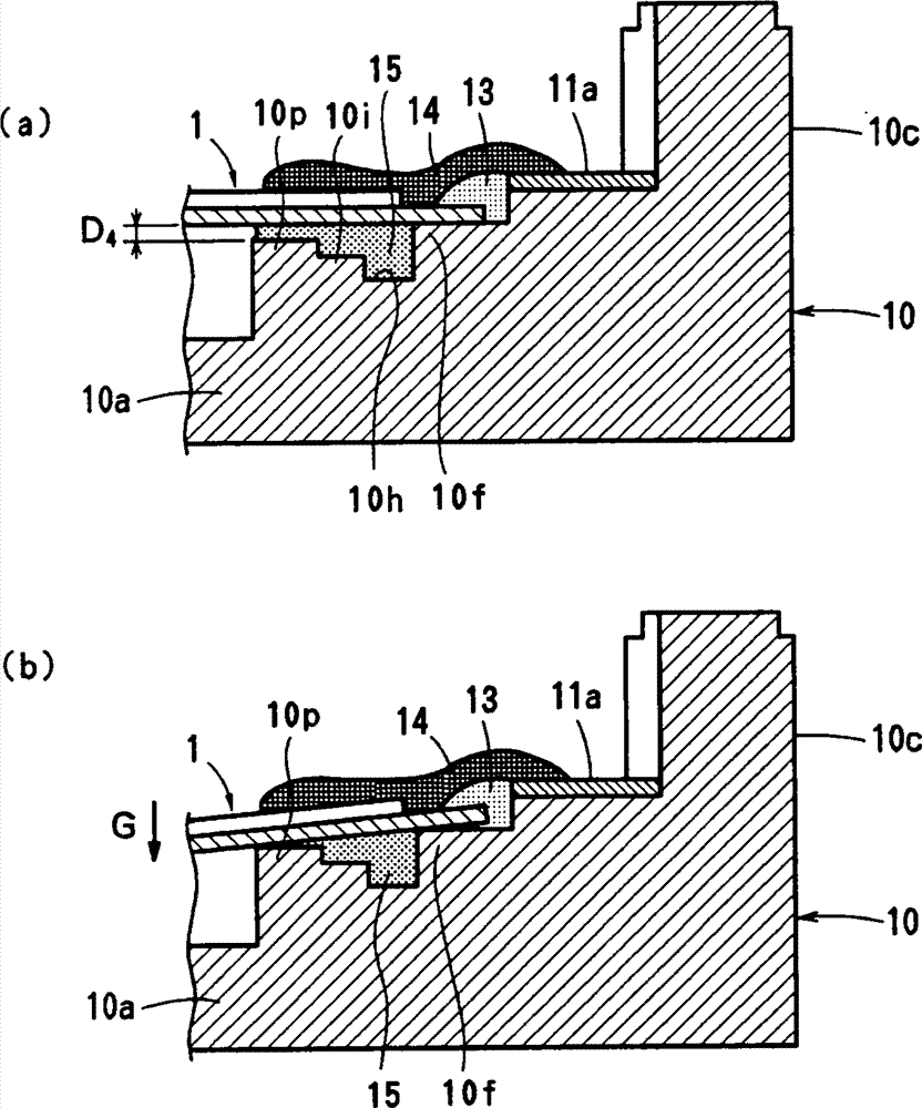
图11示出沿图7中XI-XI线所取的截面图以及表示下落冲击动作的截面图;Figure 11 shows a cross-sectional view taken along line XI-XI in Figure 7 and a cross-sectional view representing a drop impact action;
图12是表示防过振幅接收器和压电振动膜片之间距离D4与4kHz下的声压之间关系的曲线图;Fig. 12 is a graph showing the relationship between the distance D4 between the anti-overamplitude receiver and the piezoelectric vibrating diaphragm and the sound pressure at 4kHz;
图13是表示防过振幅接收器和压电振动膜片之间的距离D4与下落冲击测试中的缺陷率之间的关系曲线图;Fig. 13 is a graph showing the relationship between the distance D4 between the anti-over-amplitude receiver and the piezoelectric vibrating diaphragm and the defect rate in the drop impact test;
图14示出公知结构中压电振动膜片与接线端之间连接部分的截面图。Fig. 14 shows a cross-sectional view of the connecting portion between the piezoelectric vibrating diaphragm and the terminal in the known structure.
参考数字reference number
1: 压电振动膜片1: Piezoelectric diaphragm
2: 金属片2: metal sheet
4: 压电元件4: Piezoelectric element
6: 外电极6: External electrode
9b: 引线电极9b: Lead electrode
10: 外壳10: shell
10a: 底壁10a: bottom wall
10f: 支架10f: bracket
10p: 防过振幅接收器10p: Anti-overamplitude receiver
11和12:接线端11 and 12: Terminals
13: 第一弹性粘合剂13: The first elastic adhesive
14: 导电粘合剂14: Conductive adhesive
15: 第二弹性粘合剂15: Second elastic adhesive
具体实施方式Detailed ways
下面将描述本发明的实施例。Embodiments of the present invention will be described below.
第一实施例first embodiment
图1示出作为本发明表面安装压电电声变换器示例的压电发声器。FIG. 1 shows a piezoelectric sounder as an example of the surface-mounted piezoelectric electroacoustic transducer of the present invention.
这种压电发声器主要包括压电振动膜片1、壳体10和盖20。壳体10和盖20构成外壳。This piezoelectric sounder mainly includes a piezoelectric vibrating
参考图2和3,本实施例中的压电振动膜片1包括实质上为正方形的金属片2、形成于金属片2表面上的绝缘层3a,以及粘结并固定到绝缘层3a上的实质为正方形的压电元件4。压电元件4小于金属片2。金属片2优选地由具有弹簧弹性的材料形成,如磷青铜和42Ni合金等。绝缘层3a可以由树脂(如聚酰亚胺和环氧树脂)涂层或通过氧化形成氧化物膜形成。2 and 3, the
压电元件4包括两个压电陶瓷层4a和4b、设置在其间的内电极5、实质上设置在压电元件4的整个顶面上的外电极6,以及实质上设置在压电元件4的整个底面上的另一外电极7。通过共同烘烤其间设置有内电极5的生料片,形成两个压电陶瓷层4a和4b。对这些压电陶瓷层4a和4b沿厚度方向进行相反的极化,如图3中的箭头P所示。内电极5的一侧暴露在压电元件4的端面上,而内电极5的相对侧与压电元件4的相对表面分离预定的距离。压电元件4的外电极6和7通过侧电极8相连,而内电极5通过另一侧电极9a与顶部引线电极9b和底部引线电极9c相连。引线电极9b和9c是沿着压电元件4的一侧形成并且与外电极6和7电隔离的小电极。侧电极8的长度等于压电元件4的一边,而另一侧电极9a的长度对应于引线电极9b和9c。尽管可以省略底部引线电极9c,可将引线电极9b和9c分别形成于压电元件4的顶面和底面上,用以消除本实施例中压电元件4的方向性。此外,引线电极9b和9c的长度可以等于压电元件4的一边。利用比如环氧树脂粘合剂等粘合剂3b(参见图2),将压电元件4的底面与绝缘层3a的顶面的中心粘结在一起。金属片2大于压电元件4,具有延伸到压电元件4的外部并被绝缘层3a连续覆盖的延伸部分2a。The piezoelectric element 4 includes two piezoelectric ceramic layers 4a and 4b, an
参考图4到10,由树脂形成壳体10,它的形状为具有底壁10a和四个侧壁10b到10e的矩形盒状。壳体10的尺寸为9mm×9mm×2mm。所用的树脂优选的是阻热树脂,比如液晶聚合物(LCP)、间同立构聚苯乙烯(SPS)、聚苯硫(PPS)及环氧树脂等。通过插入并模制,将接线端11和12插入壳体10中。这些接线端11和12分别具有双叉状内连接部分11a和12a。内连接部分11a和12a分别暴露在四个侧壁10b到10e中的两个相对的侧壁10b和10d的内部。接线端11和12还分别具有暴露在壳体10的外部的外连接部分11b和12b。外连接部分11b和12b分别沿着10b和10d的外表面弯向壳体10的底面(参见图6)。Referring to FIGS. 4 to 10, a
在壳体10的四角内部形成支架10f,用以在其角部支撑振动膜片1的底面。把各支架10f布置得比接线端11和12的内连接部分11a和12a的暴露表面低一级。当把振动膜片1放置在支架10f上时,振动膜片1的顶面基本上与接线端11和12的内连接部分11a和12a的顶面一样高,或略低于内连接部分11a和12a的顶面。
在接线端11和12的内连接部分11a和12a的内部靠近支架10f的位置形成氨基甲酸酯容纳台阶10g。使这些氨基甲酸酯容纳台阶10g定位于比支架10f低的高度,用以限定氨基甲酸酯容纳台阶10g与振动膜片1的底面之间的预定间隙D1。氨基甲酸酯容纳台阶10g与振动膜片1的底面(支架10f的顶面)之间的间隙D1的高度使得能够通过粘合剂的表面张力防止第一弹性粘合剂13(后面有述)流出。如果以6到10Pa·s的粘滞度涂敷第一弹性粘合剂13,则所述间隙D1优选为大约0.1到0.2mm。在本实施例中,间隙D1为0.15mm。A
壳体10的底壁10a四周设有凹槽10h,用以填充第二弹性粘合剂15(后面有述)。在各凹槽10h的内部,设置比各支架10f低的防流壁10i,用以防止第二弹性粘合剂15流到底壁10a上。防流壁10i与振动膜片1的底面(支架10f的顶面)之间的间隙D2具有能够通过其表面张力防止第二弹性粘合剂15流出的数值。如果以0.5到2.0Pa·s的粘滞度涂敷第二弹性粘合剂15,则间隙D2优选为大约0.15到0.25mm。在本实施例中,间隙D2为0.20mm。A
按照本实施例,将各凹槽10h的底面置于比底壁10a的顶面高的高度处。凹槽10h较浅,能够以相对较少量的第二弹性粘合剂15完全填充,因而粘合剂15能够快速地扩散到整个凹槽10h中。具体地说,最好将从凹槽10h的底面到振动膜片1的底面(支架10f的顶面)之间的高度D3调整为0.30mm。尽管可以将凹槽10h和壁10i设置在底壁10a的整个四周,但将凹槽10h和壁10i设置在底壁10a四周除氨基甲酸酯容纳台阶10g外的其他区域中,以便连续延伸通过氨基甲酸酯容纳台阶10g的内部。According to the present embodiment, the bottom surface of each
凹槽10h具有与支架10f和氨基甲酸酯容纳台阶10g接触的宽端部(在四个角)。这些较宽部分可以保持过量的粘合剂15,以防止其溢出到振动膜片1的顶部。The
将两个防过振幅接收器10p设置得比支架10f更为靠近压电振动膜片1的中心,以便将振动膜片1的振动幅度限制在预定范围。将这些防过振幅接收器10p定位于壳体10的底壁10a靠近引线电极9b的角部及其对角线角部,从而自底壁10a一体地突出。在本实施例中,接收器10p邻近壁10i的内周。优选地是将接收器10p定位于涂敷导电粘合剂14的区域下面。接收器10p不必覆盖涂敷导电粘合剂14的全部区域,可以设置在紧邻面向振动膜片1的中心的区域端部的下方。确定振动膜片1的底面与防过振幅接收器10p的顶面之间的距离D4,从而使振动膜片1在正常操作中不会与接收器10p相接触。The two
如果所用的压电振动膜片1包含尺寸为7.6mm×7.6mm×0.03mm的金属片2和尺寸为6.8mm×6.0mm×0.04mm的压电元件4,而且在其四角对其进行支撑,则优选地是将距离D4调整为0.01到0.2mm。在本实施例中,将距离D4调整为0.05mm,并且接收器10p的面积为0.36mm2。以第二弹性粘合剂15填充振动膜片1与防过振幅接收器10p之间的间隙(参见图11)。If the piezoelectric vibrating
例如,若对压电发声器加给下落冲击,则加速度G会以支架10f作为支点向下弯曲振动膜片1。于是,后面将会描述,防过振幅接收器10p就限制振动膜片1的过振动幅度,以避免作用在导电粘合剂14上的过度张力,从而防止导电粘合剂14的破裂。即使所述加速度G较大,以致使振动膜片1与接收器10p相接触,但第二弹性粘合剂15可以软性地接收振动膜片1,以避免对振动膜片1的过度冲击,从而保护振动膜片1。For example, when a drop impact is applied to the piezoelectric sounder, the acceleration G bends the vibrating
图12是表示接收器10p和振动膜片1之间的距离D4与4kHz下的声压之间的关系曲线图。图12表明如果将距离D4调整为0.01mm或更大,则只需以大约0.2dB的振动就可以获得75dB或更大的4kHz下的声压。因此,压电发声器具有优异的声压特性。Fig. 12 is a graph showing the relationship between the distance D4 between the
图13是表示接收器10p和振动膜片1之间的距离D4与下落冲击测试中的缺陷率之间的关系曲线图。FIG. 13 is a graph showing the relationship between the distance D4 between the
通过将包含压电发声器的蜂窝电话从150cm的高度下跌落到混凝土表面上,并确定在经过六个方向的下落/循环的十次循环之后,导电粘合剂14是否破裂。如果导电粘合剂14破裂,则确定压电发声器有缺陷。By dropping a cellular phone containing a piezoelectric sounder from a height of 150 cm onto a concrete surface, it was determined whether or not the
图13清楚地表明如果距离D4是0.2mm或更小,缺陷率保持在0%,而如果距离D4超过0.2mm,则缺陷率会上升。这些结果证明,如果距离D4超过0.2mm,则导电粘合剂14破裂,并表现出连接可靠性下降。Figure 13 clearly shows that if the distance D4 is 0.2 mm or less, the defect rate remains at 0%, whereas if the distance D4 exceeds 0.2 mm, the defect rate rises. These results demonstrate that, if the distance D 4 exceeds 0.2 mm, the conductive adhesive 14 breaks and exhibits a decrease in connection reliability.
因此,优选地是将振动膜片1的底面与接收器10p的顶面之间的距离D4调整为0.01到0.2mm。Therefore, it is preferable to adjust the distance D4 between the bottom surface of the
在每个侧壁10b和10e的内表面上,设置两个楔形突起10j,用以导引振动膜片1的四个角。On the inner surface of each of the
在壳体10的侧壁10b到10e的内部上边缘,形成凹窝10k,用以防止第二弹性粘合剂15向上爬流。On the inner upper edges of the
还在接近侧壁10e的底壁10a上设置第一放声开孔10l。A first sound emitting opening 10l is also provided on the
在侧壁10b到10e顶面的各拐角上形成基本上呈L形的定位突起10m,用以安装和支撑盖20的各角。突起10m具有内楔形表面10n,以导引盖20。A substantially L-shaped
把压电振动膜片1安放在壳体10内部,金属片2面向底壁10a。支架10f支撑金属片2的各个角。设在侧壁10b到10e内表面上的楔形突起10j导引振动膜片1的边缘,从而将振动膜片1的各个拐角精确地放置在各支架10f上。具体地说,各楔形突起10j允许以超出振动膜片1插入精度的精度,使振动膜片1与壳体10之间的间隙变窄。这导致产品尺寸更小。另外,由于各突起10j与振动膜片1之间的接触面积较小,所以振动膜片1的振动不受妨碍。The piezoelectric vibrating
如图7所示,在把振动膜片1安放在壳体10内之后,通过将第一弹性粘合剂13涂敷于振动膜片1靠近角部的四个点,而把振动膜片1(具体为金属片2)紧固到接线端11和12的内连接部分11a和12a上。也就是将第一弹性粘合剂13涂敷在两个对角线部分,即引线电极9b与接线端11的一个内连接部分11a之间,以及顶部外电极6与接线端12的一个内连接部分12a之间。还将第一弹性粘合剂13涂敷在另两个对角线位置。在本实施例中,按照线形涂敷第一弹性粘合剂13,尽管所述形状并不局限于线形。优选地是使第一弹性粘合剂13在固化后具有500×106Pa或更小的杨氏模量。在本实施例中使用杨氏模量为3.7×10⁶Pa的氨基甲酸酯粘合剂。通过加热,固化所涂敷第一弹性粘合剂13。As shown in FIG. 7, after the vibrating
因为其粘滞度较低,涂敷时,第一弹性粘合剂13可能会通过压电振动膜片1与接线端11和12之间的间隙流到底壁10a上。如图9所示,在压电振动膜片1的下方,涂敷第一弹性粘合剂13的区域中,限定了氨基甲酸酯容纳台阶10g。氨基甲酸酯容纳台阶10g与压电振动膜片1之间的间隙D1较窄,从而借助自身的表面张力防止第一弹性粘合剂13流到底壁10a上。此外,第一弹性粘合剂13快速填充间隙D1,过量的第一弹性粘合剂13形成压电振动膜片1与接线端11和12之间的隆起块。因为第一弹性粘合剂13形成了填充氨基甲酸酯容纳台阶10g与压电振动膜片1之间间隙D1的层,所以,不会使压电振动膜片1受到过度的约束。Because of its low viscosity, the first
在第一弹性粘合剂13固化以后,在第一弹性粘合剂13上涂敷导电粘合剂14。并未具体限定所使用的导电粘合剂14;在本实施例中,使用固化后的杨氏模量为0.3×10⁹Pa的氨基甲酸酯基导电胶。通过加热,固化所涂敷的导电粘合剂14,以使引线电极9b与接线端11的内连接部分11a相连,以及使顶部外电极6与接线端12的内连接部分12a相连。还将导电粘合剂14涂敷在金属片2上,但并不直接与之接触,这是由于事先已将绝缘层3a设置在金属片2上,而且第一弹性粘合剂13覆盖了金属片2的边缘。并未具体限定所涂敷的导电粘合剂14的形状,可以是任何形状,只要允许导电粘合剂14将引线电极9b与内连接部分11a相连,以及将外电极6通过第一弹性粘合剂13的顶面与内连接部分12a相连即可。根据跨越第一弹性粘合剂13的隆起块的顶面的弧形,涂敷导电粘合剂14,从而以最短的路径延伸(参见图9)。第一弹性粘合剂13缓解了由于导电粘合剂14的固化和收缩而引起的应力,以减小其对压电振动膜片1的作用。After the first
在涂敷并固化导电粘合剂14之后,将第二弹性粘合剂15涂敷到振动膜片1的整个四周与壳体10的内部之间的间隙中,以防止空气从振动膜片1上下的空间中彼此泄漏。通过加热,固化涂敷在振动膜片1周围的第二弹性粘合剂15。优选地,所使用的第二弹性粘合剂15是固化后的杨氏模量为30×106Pa或更小并且固化前粘滞度较低,也即约0.5到2Pa·s的热固粘合剂。在本实施例中,使用杨氏模量为3.0×10⁵Pa的有机硅粘合剂。After the
涂敷第二弹性粘合剂15时,由于它的粘滞度小,所以第二弹性粘合剂15可以通过振动膜片1与壳体10之间的间隙流到底壁10a上。如图10所示,在壳体10与振动膜片1的四周相对的内部设置用以填充第二弹性粘合剂15的凹槽10h,以及在凹槽10h内侧设置防流壁10i。第二弹性粘合剂15流入凹槽10h,从而遍及整个凹槽10h。设定振动膜片1与防流壁10i之间设有间隙D2,从而通过其表面张力,将第二弹性粘合剂15保持在间隙D2中。因此,间隙D2防止第二弹性粘合剂15流到底壁10a上。此外,弹性粘合剂15形成了填充壁10i与压电振动膜片1之间的间隙D2的层,以防止压电振动膜片1的振动受到约束。When the second
在本实施例中,间隙D2略大于间隙D1(D1=0.05mm,D2=0.15mm)。第一弹性粘合剂13被部分地涂敷在振动膜片1上,即仅涂敷在压电振动膜片1和接线端11和12彼此相对的部分,而基本上围绕压电振动膜片1的整个周缘涂敷第二弹性粘合剂15。为了使第二弹性粘合剂15对压电振动膜片1的约束力最小,在第二弹性粘合剂15不泄漏的范围内,使间隙D2最大化。即使间隙D1变窄,涂敷在有限区域上的第一弹性粘合剂13的约束力的影响也较小。因此,限定间隙D1,从而使用于形成压电振动膜片1与接线端11和12之间的隆起块的粘合剂13的量最小。In this embodiment, the gap D 2 is slightly larger than the gap D 1 (D 1 =0.05mm, D 2 =0.15mm). The first
所涂敷的第二弹性粘合剂15的一部分可能会爬上并粘附在侧壁的顶面上。如果所使用的第二弹性粘合剂15是具有脱模属性的密封剂,如有机硅粘合剂等,则粘合剂15可以减小粘结到侧壁10b到10e的顶面上的盖20的结合力。因此,在侧壁10b到10e的顶边内部形成凹窝10k,用以防止第二弹性粘合剂15上爬并粘附到各侧壁的顶面上。A portion of the applied second
在如上述那样把振动膜片1装到壳体10中之后,以粘合剂21将盖20粘结到各侧壁10b到10e的顶面上。所使用的粘合剂21可为公知的粘合剂,如环氧树脂粘合剂。如果所使用的第二弹性粘合剂15是有机硅粘合剂,可以将有机硅粘合剂用作粘合剂21,因为粘合剂可以产生硅氧烷气体,并在壳体10的侧壁10b到10e的顶面上沉积形成涂层。盖20为与壳体10同样材料制成的平板。通过使盖20的周缘与壳体10的各侧壁10b到10e的顶面上的定位突起10m的楔形表面10n啮合,精确定位盖20。通过把盖20与壳体10结合,限定了盖20与振动膜片1之间的声学空间。盖20A具有第二放声开孔22。After the vibrating
这样,就完成了表面安装的压电电声变换器。In this way, the surface-mounted piezoelectric electroacoustic transducer is completed.
在本实施例中,将预定的周期性电压(交变信号或矩形信号)加于接线端11和12上,以使压电元件4在平面内扩张和收缩,而金属片2并不扩张或收缩。因此,振动膜片1可以整体弯曲并振动。于是,振动膜片1可以通过放声开孔22发出预定的声波,因为第二弹性粘合剂15密封了振动膜片1上下的空间。In this embodiment, a predetermined periodic voltage (alternating signal or rectangular signal) is applied to the
具体地说,由于支架10f在其角部以较小的支撑面积支撑振动膜片1,所以振动膜片1可以产生较高的声压。此外,电声变换器具有稳定的频率特性,因为第一弹性粘合剂13被设置在导电粘合剂14的下方,以约束由于导电粘合剂14的固化和收缩所引起的应力施加到振动膜片1上的应变。此外,固化的导电粘合剂14不会妨碍振动膜片1的振动,或者不会由于振动膜片1的振动而破裂。Specifically, since the
本发明并不局限于上述实施例,也可以在本发明的范围内改型。The present invention is not limited to the above-described embodiments, but may be modified within the scope of the present invention.
涂敷第二弹性粘合剂15的区域并不局限于振动膜片1的整个四周,如上述实施例中那样;可将它涂敷到能够密封振动膜片1与壳体10之间的间隙的任何区域。The area where the second
尽管在本实施例中,压电振动膜片1具有由金属片和与之粘合的多层压电元件4组成的结构,所使用的压电元件也可以具有单层结构。Although in this embodiment, the piezoelectric vibrating
本发明的压电振动膜片并不局限于包括金属片和与之粘合的压电元件的单片晶片(unimorph)压电振动膜片,也可以使用如日本未审专利申请公开No.2001-95094中所公开的、仅包括多层压电陶瓷元件的双片晶片(bimorph)压电振动膜片。The piezoelectric vibrating membrane of the present invention is not limited to a unimorph piezoelectric vibrating membrane comprising a metal sheet and a piezoelectric element bonded thereto, and a piezoelectric vibrating membrane such as Japanese Unexamined Patent Application Publication No. 2001 may also be used. - A bimorph piezoelectric vibrating diaphragm comprising only a multilayer piezoelectric ceramic element disclosed in 95094.
本发明中的外壳并不局限于如上述实施例中所述的包含其截面为盒状的壳体10和粘接到壳体10的顶部开口的盖20在内的外壳。例如,所使用的外壳可以包括具有底部开口的类似帽形的壳体,以及粘接到壳体底部的底板。The case in the present invention is not limited to the case including the
在上述实施例中,将接收器10p设置在两个对角线位置,尽管可以根据涂敷导电粘合剂14的位置,增加接收器10p的数量。In the above-described embodiment, the
Claims (4)
Applications Claiming Priority (3)
| Application Number | Priority Date | Filing Date | Title |
|---|---|---|---|
| JP2003429670 | 2003-12-25 | ||
| JP429670/2003 | 2003-12-25 | ||
| PCT/JP2004/015476 WO2005064989A1 (en) | 2003-12-25 | 2004-10-20 | Piezoelectric electro-acoustic converter |
Publications (2)
| Publication Number | Publication Date |
|---|---|
| CN1894999A CN1894999A (en) | 2007-01-10 |
| CN1894999B true CN1894999B (en) | 2012-12-26 |
Family
ID=34736312
Family Applications (1)
| Application Number | Title | Priority Date | Filing Date |
|---|---|---|---|
| CN200480037278.0A Expired - Lifetime CN1894999B (en) | 2003-12-25 | 2004-10-20 | Piezoelectric electro-acoustic converter |
Country Status (4)
| Country | Link |
|---|---|
| US (1) | US7671517B2 (en) |
| JP (1) | JP3844012B2 (en) |
| CN (1) | CN1894999B (en) |
| WO (1) | WO2005064989A1 (en) |
Families Citing this family (20)
| Publication number | Priority date | Publication date | Assignee | Title |
|---|---|---|---|---|
| WO2009072351A1 (en) | 2007-12-06 | 2009-06-11 | Murata Manufacturing Co., Ltd. | Piezoelectric vibration component |
| JP5223573B2 (en) * | 2008-09-30 | 2013-06-26 | マツダ株式会社 | Automobile roof structure |
| TWI455602B (en) * | 2009-01-27 | 2014-10-01 | Taiyo Yuden Kk | Piezoelectric body |
| US8556227B2 (en) * | 2009-07-20 | 2013-10-15 | Burkhard Buestgens | Temperature-compensated piezoelectric flexural transducer |
| TWI403009B (en) * | 2010-04-02 | 2013-07-21 | 中原大學 | Ring type piezoeletric device, method for processing the same, and torque sensor assembled with the same |
| DE102010027780A1 (en) | 2010-04-15 | 2011-10-20 | Robert Bosch Gmbh | Method for driving an ultrasonic sensor and ultrasonic sensor |
| WO2012060042A1 (en) * | 2010-11-01 | 2012-05-10 | Necカシオモバイルコミュニケーションズ株式会社 | Electronic equipment |
| US9054605B2 (en) * | 2010-11-19 | 2015-06-09 | Hysonic. Co., Ltd. | Haptic module using piezoelectric element |
| US20120163131A1 (en) * | 2010-12-22 | 2012-06-28 | Sondex Limited | Mono-directional Ultrasound Transducer for Borehole Imaging |
| JP6014369B2 (en) * | 2012-05-30 | 2016-10-25 | 日本発條株式会社 | Actuator mounting portion of suspension for disk device, conductive paste coating method and paste coating device |
| FR2992558B1 (en) * | 2012-06-29 | 2014-06-20 | Oreal | PROCESS FOR FORMING A COLORED PATTERN ON KERATIN FIBERS WITH A COMPOSITION COMPRISING A HYDROPHOBIC FILMOGENIC POLYMER, AT LEAST ONE VOLATILE SOLVENT AND AT LEAST ONE PIGMENT |
| WO2014045719A1 (en) * | 2012-09-19 | 2014-03-27 | 京セラ株式会社 | Sound generator, sound-generating device, and electronic device |
| KR101662126B1 (en) * | 2014-05-02 | 2016-10-05 | 주식회사 엠플러스 | Vibrator |
| DE102014106753B4 (en) | 2014-05-14 | 2022-08-11 | USound GmbH | MEMS loudspeaker with actuator structure and diaphragm spaced therefrom |
| US10572015B2 (en) * | 2014-10-24 | 2020-02-25 | Murata Manufacturing Co., Ltd. | Vibrating device and tactile sense presenting device |
| WO2018061302A1 (en) * | 2016-09-28 | 2018-04-05 | 株式会社村田製作所 | Piezoelectric sound generating component and method for manufacturing same |
| WO2018061320A1 (en) * | 2016-09-28 | 2018-04-05 | 株式会社村田製作所 | Piezoelectric sounding component |
| WO2018092730A1 (en) * | 2016-11-15 | 2018-05-24 | 株式会社村田製作所 | Respiration sensing device |
| US20190384399A1 (en) * | 2018-06-15 | 2019-12-19 | Immersion Corporation | Piezoelectric displacement amplification apparatus |
| CN110856085B (en) * | 2018-11-30 | 2021-07-09 | 美律电子(深圳)有限公司 | Loudspeaker structure |
Citations (1)
| Publication number | Priority date | Publication date | Assignee | Title |
|---|---|---|---|---|
| CN1394103A (en) * | 2001-06-26 | 2003-01-29 | 株式会社村田制作所 | Piezoelectric electroacoustic transducer and mfg. method thereof |
Family Cites Families (13)
| Publication number | Priority date | Publication date | Assignee | Title |
|---|---|---|---|---|
| DE4015253A1 (en) | 1990-05-12 | 1991-11-14 | Hoechst Ceram Tec Ag | PIEZOELECTRIC TONER AND METHOD FOR THE PRODUCTION THEREOF |
| JP2599264Y2 (en) | 1993-09-03 | 1999-08-30 | ティーディーケイ株式会社 | Piezoelectric sounding body |
| JPH10168396A (en) * | 1996-12-11 | 1998-06-23 | Araco Corp | Bonding between external plate of car body and reinforcing material and adhesive container |
| GB2345397B (en) * | 1997-08-19 | 2001-10-31 | Citizen Watch Co Ltd | Piezoelectric vibrator |
| JP3714128B2 (en) | 1999-07-22 | 2005-11-09 | 株式会社村田製作所 | Piezoelectric electroacoustic transducer |
| JP3700559B2 (en) | 1999-12-16 | 2005-09-28 | 株式会社村田製作所 | Piezoelectric acoustic component and manufacturing method thereof |
| JP2002286452A (en) * | 2001-03-26 | 2002-10-03 | Murata Mfg Co Ltd | Vibration gyro and electronic device using the same |
| JP3770111B2 (en) | 2001-07-09 | 2006-04-26 | 株式会社村田製作所 | Piezoelectric electroacoustic transducer |
| JP3669431B2 (en) * | 2001-08-20 | 2005-07-06 | 株式会社村田製作所 | Piezoelectric electroacoustic transducer |
| JP3882890B2 (en) * | 2001-10-19 | 2007-02-21 | 株式会社村田製作所 | Piezoelectric electroacoustic transducer |
| JP3861809B2 (en) * | 2002-12-27 | 2006-12-27 | 株式会社村田製作所 | Piezoelectric diaphragm and piezoelectric electroacoustic transducer using the piezoelectric diaphragm |
| JP4003686B2 (en) * | 2003-04-10 | 2007-11-07 | 株式会社村田製作所 | Piezoelectric electroacoustic transducer |
| JP3979334B2 (en) * | 2003-04-21 | 2007-09-19 | 株式会社村田製作所 | Piezoelectric electroacoustic transducer |
-
2004
- 2004-10-20 JP JP2005516550A patent/JP3844012B2/en not_active Expired - Fee Related
- 2004-10-20 CN CN200480037278.0A patent/CN1894999B/en not_active Expired - Lifetime
- 2004-10-20 WO PCT/JP2004/015476 patent/WO2005064989A1/en active Application Filing
- 2004-10-20 US US10/596,718 patent/US7671517B2/en active Active
Patent Citations (1)
| Publication number | Priority date | Publication date | Assignee | Title |
|---|---|---|---|---|
| CN1394103A (en) * | 2001-06-26 | 2003-01-29 | 株式会社村田制作所 | Piezoelectric electroacoustic transducer and mfg. method thereof |
Also Published As
| Publication number | Publication date |
|---|---|
| CN1894999A (en) | 2007-01-10 |
| JP3844012B2 (en) | 2006-11-08 |
| US20090015108A1 (en) | 2009-01-15 |
| US7671517B2 (en) | 2010-03-02 |
| JPWO2005064989A1 (en) | 2007-07-26 |
| WO2005064989A1 (en) | 2005-07-14 |
Similar Documents
| Publication | Publication Date | Title |
|---|---|---|
| CN1894999B (en) | Piezoelectric electro-acoustic converter | |
| JP3979334B2 (en) | Piezoelectric electroacoustic transducer | |
| JP3925414B2 (en) | Piezoelectric electroacoustic transducer | |
| US6570299B2 (en) | Piezoelectric electroacoustic transducer and manufacturing method of the same | |
| KR100596518B1 (en) | Piezoelectric type electroacoustic transducer | |
| US7141919B1 (en) | Piezoelectric electroacoustic transducer | |
| JP3988672B2 (en) | Piezoelectric electroacoustic transducer and manufacturing method thereof | |
| US7067959B2 (en) | Piezoelectric diaphragm and piezoelectric electroacoustic transducer using the same | |
| CN1202645C (en) | Piezoelectric electroacoustic converter | |
| JP3770111B2 (en) | Piezoelectric electroacoustic transducer | |
| US6794799B2 (en) | Piezoelectric electroacoustic transducer | |
| JP4179196B2 (en) | Piezoelectric electroacoustic transducer |
Legal Events
| Date | Code | Title | Description |
|---|---|---|---|
| C06 | Publication | ||
| PB01 | Publication | ||
| C10 | Entry into substantive examination | ||
| SE01 | Entry into force of request for substantive examination | ||
| C14 | Grant of patent or utility model | ||
| GR01 | Patent grant | ||
| CX01 | Expiry of patent term | ||
| CX01 | Expiry of patent term |
Granted publication date: 20121226 |