CN1881738B - Charge mode control circuit and method - Google Patents
Charge mode control circuit and method Download PDFInfo
- Publication number
- CN1881738B CN1881738B CN2005100353964A CN200510035396A CN1881738B CN 1881738 B CN1881738 B CN 1881738B CN 2005100353964 A CN2005100353964 A CN 2005100353964A CN 200510035396 A CN200510035396 A CN 200510035396A CN 1881738 B CN1881738 B CN 1881738B
- Authority
- CN
- China
- Prior art keywords
- charging
- charging mode
- adapter
- control circuit
- input
- Prior art date
- Legal status (The legal status is an assumption and is not a legal conclusion. Google has not performed a legal analysis and makes no representation as to the accuracy of the status listed.)
- Expired - Fee Related
Links
Images


Classifications
-
- H02J7/933—
-
- H—ELECTRICITY
- H02—GENERATION; CONVERSION OR DISTRIBUTION OF ELECTRIC POWER
- H02J—CIRCUIT ARRANGEMENTS OR SYSTEMS FOR SUPPLYING OR DISTRIBUTING ELECTRIC POWER; SYSTEMS FOR STORING ELECTRIC ENERGY
- H02J2207/00—Indexing scheme relating to details of circuit arrangements for charging or depolarising batteries or for supplying loads from batteries
- H02J2207/30—Charge provided using DC bus or data bus of a computer
Landscapes
- Charge And Discharge Circuits For Batteries Or The Like (AREA)
Abstract
本发明揭示了一种充电模式控制电路及方法,一充电模式控制电路主要由电压比较电路和充电控制电路两部分组成,充电模式控制的实现方法包括步骤:充电电源电压与参考电源电压比较,输出一个相应的高/低电平信号;将此高/低电平信号作为充电模式的控制信号,根据此信号电平的高/低对可充电电池采取相应的充电模式充电。当便携式设备通过USB连接线与计算机相连时以正常模式充电;在需要快速充电时,只需要在便携式设备和USB连接线中间加入一个带AC/DC适配器的转接装置,通过适配器为充电模式控制电路提供充电电源,就可以进行数据交换同时实现快速充电,设计简单易行,使用起来也很方便。
The invention discloses a charging mode control circuit and method. A charging mode control circuit is mainly composed of a voltage comparison circuit and a charging control circuit. The method for realizing the charging mode control includes the steps of: comparing the charging power supply voltage with the reference power supply voltage, outputting A corresponding high/low level signal; use this high/low level signal as the control signal of the charging mode, and charge the rechargeable battery in a corresponding charging mode according to the high/low level of the signal level. When the portable device is connected to the computer through the USB cable, it will be charged in the normal mode; when fast charging is required, it is only necessary to add an adapter with an AC/DC adapter between the portable device and the USB cable, and control the charging mode through the adapter The circuit provides the charging power, so that data exchange and fast charging can be realized at the same time. The design is simple and easy, and it is also very convenient to use.
Description
【技术领域】【Technical field】
本发明涉及一种充电模式控制电路及方法,特别是涉及一种带USB接口的便携式设备的充电模式控制电路及方法。The invention relates to a charging mode control circuit and method, in particular to a charging mode control circuit and method of a portable device with a USB interface.
【背景技术】【Background technique】
带USB接口的便携式设备如掌上电脑等信息存取量大、体积小、携带方便,所以自其问世以来一直备受用户青睐。为使便携式设备更好地便于用户使用,如带电时间长,便携式设备一般都内置大容量的可充电电池,对于可充电电池充电的充电模式,现有技术主要有以下两种方案。Portable devices with USB interfaces, such as handheld computers, have large information access, small size, and are easy to carry, so they have been favored by users since their advent. In order to make portable devices more convenient for users to use, such as long charging time, portable devices generally have built-in rechargeable batteries with large capacity. For the charging mode of rechargeable batteries, there are mainly the following two solutions in the prior art.
方案一:Option One:
利用外部直流适配器将市电经过变压整流滤波稳压之后给便携式设备提供充电电源对可充电电池充电。采用这种充电模式的优点在于,只要有市电的地方就可以直接利用适配器对便携式设备的可充电电池充电,而缺点在于,在充电期间计算机和便携式设备不能通过此充电接口进行数据交换。Use an external DC adapter to provide charging power for portable devices to charge the rechargeable battery after the mains power is transformed, rectified, filtered and regulated. The advantage of adopting this charging mode is that the rechargeable battery of the portable device can be directly charged by the adapter as long as there is commercial power, but the disadvantage is that the computer and the portable device cannot exchange data through the charging interface during charging.
方案二:Option II:
利用USB接口将便携式设备与计算机相连,通过USB接口为便携式设备提供充电电源对可充电电池充电。采取这种充电模式在对便携式设备充电的同时计算机和便携式设备之间还可以通过USB总线进行数据交换,使用起来十分方便,可按照USB 1.1和USB 2.0的协议标准,USB的每个端口的总线供电容量被限制在2.5瓦(0.5A@5V)以内,也就是说当USB接口提供的充电电压为+5V时,所能提供的充电电流最大不超过500mA,因而这个较小的充电电流限制了便携式设备充电的速度。The portable device is connected with the computer through the USB interface, and the charging power is provided for the portable device through the USB interface to charge the rechargeable battery. With this charging mode, while charging the portable device, the computer and the portable device can also exchange data through the USB bus, which is very convenient to use. According to the protocol standards of USB 1.1 and USB 2.0, the bus of each port of the USB The power supply capacity is limited within 2.5 watts (0.5A@5V), that is to say, when the charging voltage provided by the USB interface is +5V, the maximum charging current that can be provided does not exceed 500mA, so this small charging current limits The speed at which the portable device charges.
【发明内容】【Content of invention】
本发明提供一种充电模式控制电路,以根据不同的充电电源选取相应的充电模式对便携式设备的可充电池充电。The invention provides a charging mode control circuit for selecting a corresponding charging mode according to different charging power sources to charge a rechargeable battery of a portable device.
本发明提供一种充电模式控制方法,以根据不同的充电电源选取相应的充电模式对便携式设备的可充电池充电。The invention provides a charging mode control method to select a corresponding charging mode according to different charging power sources to charge a rechargeable battery of a portable device.
本发明还提供一种充电模式控制装置,以解决现有技术中便携式设备在和计算机进行数据交换同时不能对其可充电电池快速充电的缺点。The present invention also provides a charging mode control device to solve the disadvantage in the prior art that the portable device cannot charge its rechargeable battery rapidly while exchanging data with a computer.
为解决上述的问题,本发明提供了如下解决方案:In order to solve the above problems, the present invention provides the following solutions:
一种充电模式控制方法,其特征在于包括步骤:充电电源电压与参考电源电压比较,输出一个相应的高/低电平信号;将此高/低电平信号作为充电模式的控制信号,根据此信号电平的高/低对可充电电池采取相应的充电模式充电。根据上述方法:所述的充电电源输入的电压值不同时,就实现对可充电电池充电模式的选择。A charging mode control method is characterized in that it includes the steps of: comparing the charging power supply voltage with the reference power supply voltage, outputting a corresponding high/low level signal; using the high/low level signal as the control signal of the charging mode, according to the The high/low signal level charges the rechargeable battery in the corresponding charging mode. According to the above method: when the input voltage values of the charging power sources are different, the selection of the charging mode of the rechargeable battery is realized.
本发明的一种充电模式控制电路包括:一电压比较电路,其具有两个输入端和一个输出端;及一充电控制电路,其至少具有两个输入端和一个输出端;其特征在于:一充电电源分别从电压比较电路第一输入端和充电控制电路第一输入端输入,电压比较电路的第一输入端的充电电源电压与其第二输入端连接的参考电源比较后,输出一个高/低电平信号送到充电控制电路第二输入端作为充电模式控制信号,成而实现充电控制电路根据输入的充电电源不同对可充电电池采取相应的充电模式充电。根据上述充电模式控制电路,其中所述的充电电源可以是来自与计算机相连接的USB接口的充电电源,也可以是来自AC/DC适配器的充电电源。A charging mode control circuit of the present invention includes: a voltage comparison circuit, which has two input terminals and an output terminal; and a charging control circuit, which has at least two input terminals and an output terminal; it is characterized in that: a The charging power supply is respectively input from the first input terminal of the voltage comparison circuit and the first input terminal of the charging control circuit. After the voltage of the charging power supply at the first input terminal of the voltage comparison circuit is compared with the reference power supply connected to the second input terminal, a high/low voltage is output. The flat signal is sent to the second input terminal of the charging control circuit as a charging mode control signal, so that the charging control circuit can charge the rechargeable battery in a corresponding charging mode according to the input charging power source. According to the above charging mode control circuit, the charging power source may be a charging power source from a USB interface connected to a computer, or may be a charging power source from an AC/DC adapter.
本发明的一种充电模式控制装置,包括一具有两输入端与一输出端的电压比较电路,及一具有两输入端与一输出端的充电控制电路,其特征在于:所述充电模式控制装置还包括一转接装置,所述转接装置具有输入接口与输出接口,转接装置经由所述输入接口与一计算机相连,经由所述输出接口的引脚与一适配器及电压比较电路的第一输入端、充电控制电路的第一输入端输入相连;所述电压比较器的第二输入端连接至一参考电源,输出端连接至充电控制电路的第二输入端;及所述充电控制电路的输出端连接至可充电电池。根据上述充电模式控制装置,所述电压比较电路比较其第一输入端与第二输入端所输入的电压值,根据比较结果输出一个高/低电平信号给充电控制电路,所述充电控制电路根据此高/低电平信号对可充电电池采取相应的充电模式充电。A charging mode control device of the present invention includes a voltage comparison circuit having two input terminals and an output terminal, and a charging control circuit having two input terminals and an output terminal, wherein the charging mode control device further includes A switching device, the switching device has an input interface and an output interface, the switching device is connected to a computer through the input interface, and the pin of the output interface is connected to an adapter and the first input terminal of the voltage comparison circuit , the first input terminal of the charging control circuit is connected to the input; the second input terminal of the voltage comparator is connected to a reference power supply, and the output terminal is connected to the second input terminal of the charging control circuit; and the output terminal of the charging control circuit Connect to rechargeable battery. According to the above charging mode control device, the voltage comparison circuit compares the voltage values input by its first input terminal and the second input terminal, and outputs a high/low level signal to the charging control circuit according to the comparison result, and the charging control circuit According to this high/low level signal, the rechargeable battery is charged in the corresponding charging mode.
本发明在不影响计算机和便携式设备之间进行数据交换的基础上,兼容了现有技术的普通充电模式的同时还提供了一种对便携式设备快速充电模式。采用这种快速充电模式时,只需要在便携式设备和连接于计算机的连接线之间加入一个带AC/DC适配器的转接装置,通过适配器可以为充电模式控制电路提供一个较大电流的充电电源,就可以使计算机和便携式设备之间进行数据交换的同时对便携式设备快速充电,设计简单易行,使用起来也很方便。On the basis of not affecting the data exchange between the computer and the portable device, the present invention is compatible with the common charging mode in the prior art and also provides a fast charging mode for the portable device. When using this fast charging mode, it is only necessary to add an adapter with an AC/DC adapter between the portable device and the cable connected to the computer, and the adapter can provide a large current charging power supply for the charging mode control circuit , it can quickly charge the portable device while exchanging data between the computer and the portable device, the design is simple and easy, and the use is also very convenient.
【附图说明】【Description of drawings】
图1是本发明充电模式控制电路一具体应用的示意图。FIG. 1 is a schematic diagram of a specific application of the charging mode control circuit of the present invention.
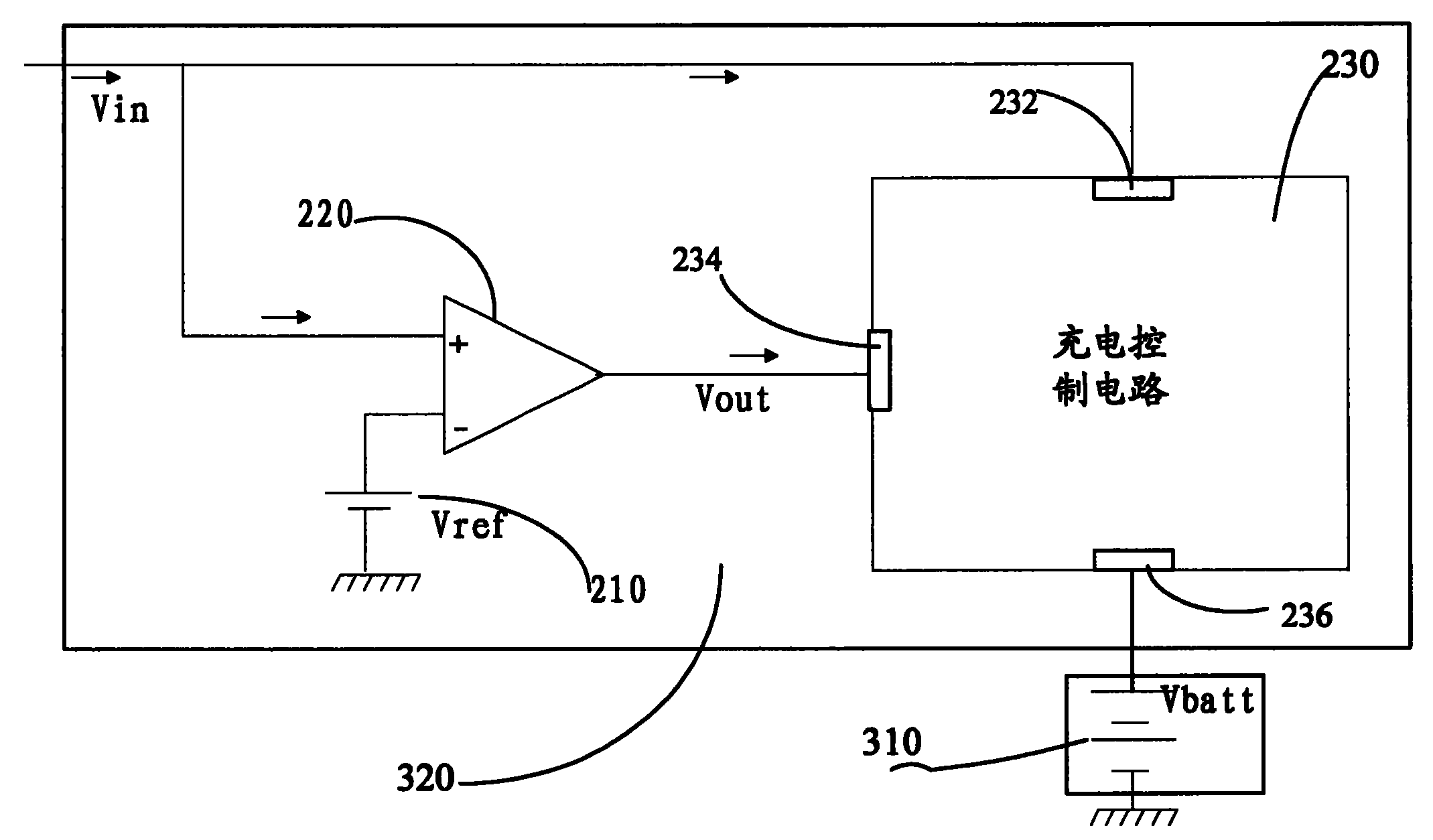
图2是本发明充电模式控制电路的一具体实施方式的电路图。FIG. 2 is a circuit diagram of a specific embodiment of the charging mode control circuit of the present invention.
【具体实施方式】【Detailed ways】
本发明根据充电电源电压的不同与参考电源电压比较后,输出一个相应的高/低电平信号,作为充电模式的控制信号,根据此信号电平的高/低对可充电电池分别采取不同的充电模式充电。The present invention outputs a corresponding high/low level signal as the control signal of the charging mode after comparing the voltage of the charging power supply with the reference power supply voltage. Charging mode charging.
参阅图1,是本发明充电模式控制电路一具体应用的示意图。在该具体应用中,本发明的充电模式控制电路320置于一便携式设备30中,以根据输入的充电电源的不同控制便携式设备30中可充电电池310的充电模式。便携式设备30通过一转接装置40与一计算机10及一AC/DC适配器440相连,以便在和计算机10之间进行数据交换的同时,从AC/DC适配器440处获取较大的充电电流,以快速充电模式对可充电电池310充电。 便携式设备30通过USB接口330与转接装置40的USB接口410相耦接,转接装置40又通过一USB接口420与USB线缆50连接至计算机10的USB接口110。该转接装置40还通过具有两线缆的电力线430耦合至AC/DC适配器440。在该转接装置内部,USB接口420与USB接口410的引脚除Vcc断开外其它三个引脚Ground、D+和D-均为直接耦合。电力线430的两线缆:电源线以及接地线分别与USB接口410的引脚Vcc以及Ground相连接。因此,通过转接装置40以及转接装置40与计算机10及AC/DC适配器440之间的连接,便携式设备30在无需终止与计算机10之间进行数据交换的情况下,从AC/DC适配器440处获得较大的充电电流以快速充电模式充电。本发明的具体实施方式中,当移走转接装置40后,计算机10的USB接口110和便携式设备30的USB接口330通过USB线缆50直接相连接时,计算机10可以给整合在便携式设备30的充电模式控制电路320提供一个电压为5V最大电流不超过500mA的充电电源,此时便携式设备可以实现在和计算机进行数据交换的同时以普通充电模式充电。Referring to FIG. 1 , it is a schematic diagram of a specific application of the charging mode control circuit of the present invention. In this specific application, the charging
参阅图2,是以电压比较器作为电压比较电路的充电模式控制电路的一具体实施方式的电路图,包括一电压比较器220与一充电控制电路230。电压比较器220的第一输入端以及充电控制电路的充电电源端口232与便携式设备30的USB接口330的电源引脚Vcc相连。电压比较器220的第二输入端连接一电压值为Vref的参考电源210,输出端Vout与充电控制电路230充电控制端234相连接。充电控制电路230的充电端口236与可充电电池310相连接。Referring to FIG. 2 , it is a circuit diagram of a specific embodiment of a charging mode control circuit using a voltage comparator as a voltage comparator circuit, including a
首先,从便携式设备30的USB接口26的电源引脚Vcc处输出的的充电电压Vin从电压比较器220第一输入端输入后,电压比较器220将其与从第二输入端输入的参考电压值Vref相比较,根据比较结果输出一个相应的高/低电平信号至充电控制电路的充电控制端234。例如,当充电电源来自AC/DC适配器440时,USB接口330的电源引脚Vcc处输出的的充电电压Vin为6V,充电电流为1A,当充电电源来自计算机10时,USB接口330的电源引脚Vcc处输出的的充电电压Vin电压为5V,充电电流小于500mA。此时设置电压比较器220的参考电压值Vref为5.5V。则当输入的充电电源来自于计算机10时,其充电电源电压只有5V,小于参考电压Vref的5.5V,此时电压比较器220输出一个低电平信号;当输入的充电电源来自于AC/DC适配器440时,其充电电源电压为6V,大于参考电压Vref的5.5V,此时电压比较器220输出一个高电平信号。First, after the charging voltage Vin output from the power supply pin Vcc of the USB interface 26 of the
在根据输入的充电电源电压的大小输出相应的高低电平后,就可以根据将此高/低电平信号Vout作为充电模式的控制信号,决定对可充电电池310采取相应的充电模式充电。当充电控制电路230接受的充电控制端234信号为高电平时,其会自动识别充电电源来自AC/DC适配器440提供的大电流电源,从而决定对可充电电池310采取充电电压为6V充电电流为1A的快速充电模式进行充电;当充电控制电路230接受的充电控制端234信号为低电平时,其会自动识别充电电源来自计算机10提供的小电流电源,从而决定对可充电电池310采取充电电压为5V充电电流小于500mA的普通充电模式进行充电。After outputting the corresponding high and low levels according to the input charging power voltage, the
本发明的充电模式控制电路中关于来自适配器440的充电电源的电压值和电流值不限于6V和1A,电压值可以大于或者小于6V,电流值也可以大于或者小于1A。电压比较器220相应的参考电压也不限于5.5V,其值介于两充电电源电压值之间就可以实现电压比较。The voltage value and current value of the charging power source from the
Claims (9)
Priority Applications (2)
| Application Number | Priority Date | Filing Date | Title |
|---|---|---|---|
| CN2005100353964A CN1881738B (en) | 2005-06-17 | 2005-06-17 | Charge mode control circuit and method |
| US11/309,005 US20060284595A1 (en) | 2005-06-17 | 2006-06-07 | Charging mode control circuit and method |
Applications Claiming Priority (1)
| Application Number | Priority Date | Filing Date | Title |
|---|---|---|---|
| CN2005100353964A CN1881738B (en) | 2005-06-17 | 2005-06-17 | Charge mode control circuit and method |
Publications (2)
| Publication Number | Publication Date |
|---|---|
| CN1881738A CN1881738A (en) | 2006-12-20 |
| CN1881738B true CN1881738B (en) | 2011-06-22 |
Family
ID=37519795
Family Applications (1)
| Application Number | Title | Priority Date | Filing Date |
|---|---|---|---|
| CN2005100353964A Expired - Fee Related CN1881738B (en) | 2005-06-17 | 2005-06-17 | Charge mode control circuit and method |
Country Status (2)
| Country | Link |
|---|---|
| US (1) | US20060284595A1 (en) |
| CN (1) | CN1881738B (en) |
Families Citing this family (32)
| Publication number | Priority date | Publication date | Assignee | Title |
|---|---|---|---|---|
| US8242742B2 (en) | 2007-06-06 | 2012-08-14 | O2Micro, Inc | Chargers, systems and methods for detecting a power source |
| KR101494900B1 (en) * | 2007-07-25 | 2015-02-24 | 삼성전자주식회사 | Mobile phone and method for charging through discernment charging cable |
| KR101477056B1 (en) * | 2008-02-01 | 2014-12-30 | 삼성전자주식회사 | Method and apparatus for checking device connecting with potable device |
| US20110227536A1 (en) * | 2010-03-17 | 2011-09-22 | Bourilkov Jordan T | Battery with universal charging input |
| CN102437623B (en) * | 2010-09-29 | 2014-07-02 | 联想(北京)有限公司 | Adapter, terminal device, USB (universal serial bus) connection device and charging base station |
| CN102570520A (en) * | 2010-12-22 | 2012-07-11 | 深圳富泰宏精密工业有限公司 | Charging circuit and charging method thereof |
| KR101835007B1 (en) | 2011-10-25 | 2018-03-07 | 삼성전자주식회사 | Apparatus and mathod for controlling charge current in portable terminal |
| CN103762702B (en) * | 2014-01-28 | 2015-12-16 | 广东欧珀移动通信有限公司 | Charging device of electronic appliances and power supply adaptor thereof |
| EP3101770B1 (en) * | 2014-01-28 | 2019-05-15 | Guangdong Oppo Mobile Telecommunications Corp., Ltd | Power adapter and terminal |
| CN103762690B (en) * | 2014-01-28 | 2016-08-24 | 广东欧珀移动通信有限公司 | Charging system |
| DK3101762T3 (en) * | 2014-01-28 | 2019-03-18 | Guangdong Oppo Mobile Telecommunications Corp Ltd | POWER ADAPTERS, TERMINAL AND METHOD OF TREATING IMPEDANCE HOURS IN A CHARGING CIRCUIT |
| CN106385094B (en) * | 2014-01-28 | 2019-02-12 | Oppo广东移动通信有限公司 | Fast charging control method and system |
| CN104810873B (en) | 2014-01-28 | 2018-03-16 | 广东欧珀移动通信有限公司 | Electronic device charging control device and method |
| WO2015113466A1 (en) * | 2014-01-28 | 2015-08-06 | 广东欧珀移动通信有限公司 | Power adapter, terminal, and method for processing exception of charging loop |
| CN104810877B (en) * | 2014-01-28 | 2016-12-14 | 广东欧珀移动通信有限公司 | Battery charging device and method |
| US10998734B2 (en) | 2014-01-28 | 2021-05-04 | Guang Dong Oppo Mobile Telecommunications Corp., Ltd. | Power adapter and terminal |
| TWI508412B (en) | 2014-03-25 | 2015-11-11 | Hon Hai Prec Ind Co Ltd | Charging device |
| US9502914B2 (en) * | 2014-10-31 | 2016-11-22 | Chicony Power Technology Co., Ltd. | Charging apparatus for recognizing adaptor and charging method for recognizing adaptor |
| CN108736539B (en) * | 2014-11-11 | 2022-09-09 | Oppo广东移动通信有限公司 | Charging Cables and Terminals |
| CN106415973B (en) * | 2014-11-11 | 2020-08-28 | Oppo广东移动通信有限公司 | Communication method, power adapter and terminal |
| US10424954B2 (en) | 2014-11-11 | 2019-09-24 | Guangdong Oppo Mobile Telecommunications Corp., Ltd. | Power adaptor, terminal and charging system |
| CN104820387A (en) * | 2015-04-27 | 2015-08-05 | 江苏紫米电子技术有限公司 | USB power supply interface-based intelligent power source |
| DK3142221T3 (en) * | 2015-05-13 | 2019-04-23 | Guangdong Oppo Mobile Telecommunications Corp Ltd | Quick charge method, power adapter and mobile terminal |
| CN106532790B (en) * | 2015-09-11 | 2020-01-03 | 技嘉科技股份有限公司 | Mobile power supply device and power supply control method thereof |
| ES2896245T3 (en) * | 2016-01-05 | 2022-02-24 | Guangdong Oppo Mobile Telecommunications Corp Ltd | Fast charging method, mobile terminal and power adapter |
| SG11201700428UA (en) | 2016-02-05 | 2017-09-28 | Guangdong Oppo Mobile Telecommunications Corp Ltd | Charge method, adapter and mobile terminal |
| JP6483325B2 (en) | 2016-02-05 | 2019-03-13 | 広東欧珀移動通信有限公司 | Terminal charging system, charging method and power adapter |
| TWI611648B (en) * | 2017-01-18 | 2018-01-11 | 廣達電腦股份有限公司 | Bidirectional charge and discharge circuit architecture |
| KR102529509B1 (en) * | 2018-05-15 | 2023-05-04 | 현대자동차주식회사 | Control method of reservation-based charging device for vehicle |
| CN108599320A (en) * | 2018-06-04 | 2018-09-28 | 深圳英集芯科技有限公司 | A kind of wireless charging system |
| US12244160B2 (en) * | 2021-07-11 | 2025-03-04 | Harman International Industries, Incorporated | System and method for delivering power to a portable device |
| FR3161960A1 (en) * | 2024-05-02 | 2025-11-07 | Somfy Activites Sa | Method for controlling an electromechanical actuator for a blackout device and associated electromechanical actuator |
Citations (4)
| Publication number | Priority date | Publication date | Assignee | Title |
|---|---|---|---|---|
| US5345162A (en) * | 1991-09-19 | 1994-09-06 | Toshiba Battery Co., Ltd. | Charging circuit of secondary battery |
| CN1169617A (en) * | 1996-05-22 | 1998-01-07 | 杨泰和 | Intermittent switching adjustable DC power supply circuit |
| US6465987B1 (en) * | 2000-10-17 | 2002-10-15 | Hewlett-Packard Company | Power source of peripheral devices |
| CN1558541A (en) * | 2004-01-13 | 2004-12-29 | 台达电子工业股份有限公司 | Modular Power Supply System |
Family Cites Families (3)
| Publication number | Priority date | Publication date | Assignee | Title |
|---|---|---|---|---|
| US6980204B1 (en) * | 2000-09-21 | 2005-12-27 | Jeffrey Charles Hawkins | Charging and communication cable system for a mobile computer apparatus |
| US6605879B2 (en) * | 2001-04-19 | 2003-08-12 | Powerware Corporation | Battery charger control circuit and an uninterruptible power supply utilizing same |
| US6498461B1 (en) * | 2001-08-17 | 2002-12-24 | O2 Micro International Limited | Voltage mode, high accuracy battery charger |
-
2005
- 2005-06-17 CN CN2005100353964A patent/CN1881738B/en not_active Expired - Fee Related
-
2006
- 2006-06-07 US US11/309,005 patent/US20060284595A1/en not_active Abandoned
Patent Citations (4)
| Publication number | Priority date | Publication date | Assignee | Title |
|---|---|---|---|---|
| US5345162A (en) * | 1991-09-19 | 1994-09-06 | Toshiba Battery Co., Ltd. | Charging circuit of secondary battery |
| CN1169617A (en) * | 1996-05-22 | 1998-01-07 | 杨泰和 | Intermittent switching adjustable DC power supply circuit |
| US6465987B1 (en) * | 2000-10-17 | 2002-10-15 | Hewlett-Packard Company | Power source of peripheral devices |
| CN1558541A (en) * | 2004-01-13 | 2004-12-29 | 台达电子工业股份有限公司 | Modular Power Supply System |
Non-Patent Citations (1)
| Title |
|---|
| JP特开平8-140281A 1996.05.31 |
Also Published As
| Publication number | Publication date |
|---|---|
| CN1881738A (en) | 2006-12-20 |
| US20060284595A1 (en) | 2006-12-21 |
Similar Documents
| Publication | Publication Date | Title |
|---|---|---|
| CN1881738B (en) | Charge mode control circuit and method | |
| KR101494900B1 (en) | Mobile phone and method for charging through discernment charging cable | |
| CN108365469B (en) | Hub with Composite Power | |
| CN106329240B (en) | Concentrator | |
| KR101318512B1 (en) | Dedicated power supply apparatus, terminal, power supply system, and power supply method | |
| CN108988431B (en) | Multi-protocol charging device and multi-protocol charging method | |
| KR100979845B1 (en) | Integrated circuits and signal processing devices using the same | |
| CN110829523A (en) | Electronic equipment and reverse charging method | |
| US20090113093A1 (en) | Mobile storage device | |
| CN108123515A (en) | Chargeable electronic equipment | |
| CN105281398A (en) | Portable device, cable assembly, and USB system | |
| JP2016531368A (en) | Apparatus and method for changing current limit value | |
| TW201504811A (en) | Power adapter and electronic device | |
| CN113009995A (en) | Power supply device and power supply method | |
| CN222191879U (en) | A multi-protocol compatible fast charging control device | |
| CN1933280B (en) | Charging mode control method and circuit | |
| CN202076618U (en) | Concentrator for transmitting data and charging simultaneously | |
| CN1881739B (en) | Charging mode control circuit and method | |
| CN106921192A (en) | Terminal and electricity sharing method | |
| CN206878506U (en) | A kind of data wire and adapter | |
| CN102163781B (en) | Hub capable of realizing data transmission and charge simultaneously | |
| CN2739695Y (en) | Portable electronic device and its charging device charging interface and expanding head | |
| TW201814543A (en) | Apparatus and method for USB charge and communication | |
| CN201956711U (en) | Platform for providing charging service for equipment to be charged | |
| CN108011416A (en) | Chargeable electronic equipment |
Legal Events
| Date | Code | Title | Description |
|---|---|---|---|
| C06 | Publication | ||
| PB01 | Publication | ||
| C10 | Entry into substantive examination | ||
| SE01 | Entry into force of request for substantive examination | ||
| C14 | Grant of patent or utility model | ||
| GR01 | Patent grant | ||
| CF01 | Termination of patent right due to non-payment of annual fee |
Granted publication date: 20110622 Termination date: 20140617 |
|
| EXPY | Termination of patent right or utility model |