CN1881593A - Electro-optical display device and method for manufacturing same - Google Patents
Electro-optical display device and method for manufacturing same Download PDFInfo
- Publication number
- CN1881593A CN1881593A CN 200610073326 CN200610073326A CN1881593A CN 1881593 A CN1881593 A CN 1881593A CN 200610073326 CN200610073326 CN 200610073326 CN 200610073326 A CN200610073326 A CN 200610073326A CN 1881593 A CN1881593 A CN 1881593A
- Authority
- CN
- China
- Prior art keywords
- film
- electrode
- photoresist pattern
- layer
- drain electrode
- Prior art date
- Legal status (The legal status is an assumption and is not a legal conclusion. Google has not performed a legal analysis and makes no representation as to the accuracy of the status listed.)
- Pending
Links
Images


Landscapes
- Thin Film Transistor (AREA)
- Liquid Crystal (AREA)
- Electroluminescent Light Sources (AREA)
- Electrodes Of Semiconductors (AREA)
- Internal Circuitry In Semiconductor Integrated Circuit Devices (AREA)
- Solid State Image Pick-Up Elements (AREA)
Abstract
The present invention provides simplified manufacture process of TFT structure of different source electrode/drain electrode materials and one electro-optical display device capable of controlling the thickness of semiconductor film layer forming the TFT channels accurately for homogeneous display. The drain electrode is configured to extend from the active region to the transparent insulating substrate below the pixel electrode. The source electrode and the source wire are so configured that their ends are in the back of the semiconductor film, and the drain electrode on the active region has also end in the back of the semiconductor film.
Description
Technical field
The present invention relates to Eletro-optical display apparatus and manufacture method thereof, particularly be provided with active array type Eletro-optical display apparatus and the manufacture method thereof of thin-film transistor (TFT) as switch element.
Background technology
Use on liquid crystal or the Eletro-optical display apparatus of organic EL (electroluminescence), extensively adopt on the substrate with switch element array shape setting such as thin-film transistor and to each display pixel and apply the independently active matrix TFT array substrate of picture signal as electrooptic cell.
For improving the productivity of this Eletro-optical display apparatus, be necessary to reduce the manufacturing process of tft array substrate, for example disclose the technology of minimizing photomechanical process operation in the patent documentation 1 by Figure 54~Figure 63, and disclose the method for making the tft array substrate with 5 times photomechanical process operation.
For example, in the manufacturing process of the source/drain electrode of Figure 58, the TFT shown in Figure 59 of patent documentation 1 and groove, after disclosing film forming and constituting Ti (titanium) metal film of etc.ing of source/drain electrode, utilize the photomechanical process operation with the photoresist patterning, and employing HF+H
2The etching solution of O component carries out wet etching, with the ohmic contact (n of Ti film and semiconductor layer
+Amorphous silicon (a-Si)) the film etching, the operation of formation source/drain electrode and groove.
But, in this case, at first in first etching work procedure, remove the Ti film of the about 300nm of thickness after, remove the ohmic contact film of the about 20nm of thickness in second etching work procedure of following.
Usually in first etching work procedure, all remove behind the Ti film to preventing the generation of etch residue, carry out over etching again.Consider the deviation of etch residue thickness, the over etching time is being starting point according to the slowest regional etched time of distribution etching speed in the substrate surface.
At this moment, therefore second etching work procedure according to the distribution of Ti film etching speed, produces deviation from the moment that the Ti film is removed fully on etching period.The time deviation of this second etching work procedure becomes the reason that causes as the a-Si film thickness deviation of TFT groove.This deviation becomes the deviation of the conduction and cut-off characteristic of TFT, might produce to show unfavorable conditions such as irregular.
In addition, in above-mentioned operation, can consider to remove Ti film and ohmic contact film (n with the dry ecthing of adopting gas without wet etching
+The a-Si film) method.But adopting general dry etching gas is Cl
2In the process of (chlorine) gas dry ecthing Ti film, n
+The etching speed of a-Si film roughly identical with the Ti film, therefore be difficult to control the thickness that becomes the a-Si of above-mentioned TFT groove film, have the problem that deviation takes place.
As addressing this is that method, can consider to have the method for the metal film formation source/drain electrode of etching selectivity with relative a-Si film.For example, after film forming Cr (chromium) or Mo (molybdenum) film, utilize the photomechanical process operation with the photoresist patterning, adopt the etching solution of ammonium ceric nitrate+nitrose component when in first etching work procedure, for example being the Cr film, and adopt when being the Mo film etching solution of phosphoric acid+nitric acid+acetate type component to carry out etching, with Cr film or Mo film patterning and formation source/drain electrode.In this wet etching operation, ohmic contact film (n
+The a-Si film) can be not etched.
Then, in second etching work procedure by utilizing Cl
2Gas or CF
4(or SF
6)+O
2The dry ecthing method of gas is with ohmic contact film (n
+The a-Si film) etching, the groove of TFT is exposed.In this case, can only carry out for the control of the thickness deviation of the a-Si film of groove with second etching work procedure.
But, in this method, have metal film kind or the very restricted problem of manufacturing procedure as source/drain electrode.
When for example wanting that source/drain electrode carried out high-precision Precision Machining,, adopt known Cl when for example being generally the Cr film if use the dry ecthing method that machining accuracy is better than wet etch method
2Gas and adopt known fluorine type gas (CF when being the Mo film
4Or SF
6) dry ecthing, n at this moment
+The etching speed of a-Si film roughly identical with Cr film or Mo film, therefore produce the same problem of occasion with above-mentioned Ti film.
In addition, when the metal film that has an etching selectivity with relative a-Si film forms source/drain electrode, metal film is confined to Cr film, Mo film or Al (aluminium) film, its range of choice is very narrow when therefore for example responding requirements such as resistance or thermal endurance or corrosion resistance with the metal film optimization, exists Eletro-optical display apparatus can not obtain the problem of sufficient characteristic.
On the other hand, such method is disclosed in the patent documentation 2: on the photoresist pattern that the semiconductor layer of formation source/drain electrode layer is used, make the raceway groove of semiconductor layer form photoresist thickness attenuation on the part in advance, adopt the dry ecthing method of mixture of oxygen in the dry etching gas, to become semiconductor film (a-Si film) etching of source/drain electrode layer, simultaneously according to podzolization with the thin part photoresist etching of above-mentioned thickness, be set with to becoming the n of groove the time difference
+The etching of a-Si film.
But in this method, carry out etching to the semiconductor film that reaches hundreds of mm * hundreds of mm scopes zone, count simultaneously μ m~very narrow zone of tens of μ m photoresist ashing and to the n of its lower floor
+The etching of a-Si film, therefore exist and be difficult to control the thickness that becomes the a-Si of groove film, and the problem of deviation takes place.
Form source/drain electrode in addition, therefore have to use relative a-Si film to have the metal membrane material of etching selectivity, still have source/very narrow problem of drain electrode material range of choice thereafter.
Patent documentation 1: the spy opens flat 8-50308 communique
Patent documentation 2: the spy opens flat 10-163174 communique
Summary of the invention
As described above, disclosed technology may produce deviation at the thickness of the a-Si film that becomes the TFT groove in the patent documentation 1, and this becomes the deviation of the conduction and cut-off characteristic of TFT, produces to show unfavorable conditions such as irregular.
In addition, when adopting the metal film that has etching selectivity by relative a-Si film to form the method for source/drain electrode, there are metal film kind or the very restricted problem of manufacturing procedure as source/drain electrode.
In addition, in patent documentation 2 in the disclosed technology, on the photoresist pattern during semiconductor pattern of formation source/drain electrode layer, make the photoresist thickness attenuation on the semiconductor pattern raceway groove formation part in advance, adopt the dry ecthing method of mixture of oxygen in the dry etching gas, to become semiconductor film (a-Si film) etching of source/drain electrode layer, according to podzolization above-mentioned thickness is approached photoresist etching partly simultaneously, but owing to reach the etching of the semiconductor film in hundreds of mm * hundreds of mm scopes zone, the ashing of the photoresist in number μ m~very narrow zone of tens of μ m with and their n of lower floor
+The etching etc. of a-Si film carry out simultaneously, therefore exist to be difficult to control the thickness that becomes the a-Si of groove film, and produce the problem of deviation at thickness.
The present invention forms for solving problem design as described above, aim to provide such Eletro-optical display apparatus: in the active array type Eletro-optical display apparatus, the manufacturing process of the TFT structural portion that simplification is made of gate electrode, gate insulating film, groove, source/drain electrode layer and source/drain electrode, do not limit simultaneously source/drain electrode material, and accurately control becomes the semiconductor layer thickness of TFT groove, and controls its deviation and prevent that the demonstration that causes because of the TFT characteristic deviation is irregular.
Eletro-optical display apparatus according to first aspect present invention, comprising the active matrix substrate, described active matrix substrate comprises: the insulating properties substrate, array-like disposes and is provided with a plurality of display pixels of the pixel electrode that is electrically connected with thin-film transistor on described insulating properties substrate, described thin-film transistor is scanned successively the grid wiring of selection, and supply with the source wiring of the signal of telecommunication, and overlook orthogonal thereto rectangular of described grid wiring and described source wiring to described pixel electrode; Described thin-film transistor is provided with from the active region layer of the semiconductor film branch that is configured in described source wiring lower floor, and the source electrode and the drain electrode that on the layer of described active region, dispose selectively across the interval, on the layer of described active region, at least described source electrode is configured to make layer any endface position in the described relatively active region of its endface position to step back more than the preset distance, described drain electrode extends to the described insulating properties substrate top ground configuration of pixel display area from described active region layer, and the described drain electrode lower floor in the described pixel display area is not provided with described active region layer.
Manufacture method according to the Eletro-optical display apparatus of third aspect present invention, described Eletro-optical display apparatus comprises active matrix substrate, described active matrix substrate comprises: the insulating properties substrate, array-like disposes and is provided with a plurality of display pixels of the pixel electrode that is electrically connected with thin-film transistor on described insulating properties substrate, described thin-film transistor is scanned successively the grid wiring of selection, and supply with the source wiring of the signal of telecommunication, and overlook orthogonal thereto rectangular of described grid wiring and described source wiring to described pixel electrode; The manufacture method of described Eletro-optical display apparatus comprises following operation: carrying out the photomechanical process first time behind film forming first conductive membrane on the described insulating properties substrate, with the operation (a) of described grid wiring patterning; Above the described grid wiring successively behind film forming dielectric film, semiconductor film and the ohmic contact film, carry out the photomechanical process second time, with described semiconductor film and described ohmic contact film patterning, form the lower membrane of described source wiring, and form from the operation (b) of the active region layer of described semiconductor film branch; And afterwards in described operation (b), on described insulating properties substrate is whole behind film forming second conductive membrane, operation (c) with the described second conductive membrane patterning, described operation (c) also comprises: carry out photomechanical process for the third time, on described second conductive membrane, formation extends to the described insulating properties substrate top of pixel display area from described lower membrane and described active region layer, and the operation (c-1) of the first photoresist pattern that approaches with the corresponding relative other parts of the corresponding portion of raceway groove of the groove of described thin-film transistor; Remove not by the operation (c-2) of described second conductive membrane of the described first photoresist pattern covers by etching; In described operation (c-2) afterwards, with the described first photoresist pattern ashing and filming, remove described raceway groove correspondence portion simultaneously, become the operation (c-3) of the second photoresist pattern of peristome; And via the described peristome of the described second photoresist pattern, remove described second conductive membrane corresponding and described ohmic contact film successively by etching with described groove, remove successively not by described second conductive membrane of the described second photoresist pattern covers and described ohmic contact film by etching simultaneously, on the layer of described active region across at interval with source electrode and drain electrode patterning, simultaneously with the operation (c-4) of described source wiring patterning.
Eletro-optical display apparatus according to first aspect present invention, because on the layer of described active region, at least described source electrode is configured to make layer any endface position in the described relatively active region of its endface position to step back more than the preset distance, with source electrode and drain electrode patterning the time, be attached to active region layer end face even if constitute the material of these electrodes again as conductive material, can prevent that also source electrode and drain electrode from conducting by these conductive materials.In addition, drain electrode lower floor does not have the active region layer in pixel display area, when therefore the present invention being applicable to pixel display area irradiation backlight optical transmission type liquid crystal indicator, light can not shine the active region layer, therefore the electric current that takes place because of optical excitation can be suppressed, the deterioration of the cut-off characteristics of thin-film transistor can be prevented.
Manufacture method according to the Eletro-optical display apparatus of third aspect present invention, in operation (c) with the second conductive membrane patterning, form the first photoresist pattern by photomechanical process for the third time, at first, removing not by etching is not needed part by second conductive membrane of the first photoresist pattern covers, then, the first photoresist pattern ashing is formed the second photoresist pattern, peristome via the second photoresist pattern, remove second conductive membrane corresponding and ohmic contact film successively by etching with groove, remove successively not by second conductive membrane of the second photoresist pattern covers and ohmic contact film by etching simultaneously, thereby on the layer of active region with source electrode and drain electrode patterning, simultaneously with the source wiring patterning, therefore can form thin-film transistor by 3 times photomechanical process operation, can simplify manufacturing process.In addition, with the first photoresist pattern ashing rear filmization, and except that dechannelling corresponding portion, formation becomes the second photoresist pattern of peristome, therefore the second photoresist pattern in the in-plane size less than the first photoresist pattern, by utilizing the etching of this second photoresist pattern, at least the source electrode can be configured to make any endface position of its endface position relative activity district floor to step back more than the preset distance, during therefore with second conductive membrane and the dry ecthing of ohmic contact film, be attached to etching face even if constitute the material of these films again as conductive material, also can prevent the situation that source electrode and drain electrode conduct because of these conductive materials.In addition, peristome via the second photoresist pattern, remove second conductive membrane corresponding and ohmic contact film successively by etching with groove, therefore when the metal film that does not have an etching selectivity with relative semiconductor film and ohmic contact film forms second conductive membrane, when perhaps using the etching work procedure of no etching selectivity, second conductive membrane and ohmic contact film well can both be controlled and removed, can accurately control the thickness of the semiconductor film that constitutes thin film transistor channel portion, and can suppress its deviation, therefore can prevent that the display unit that the deviation because of tft characteristics causes from showing irregular.
Description of drawings
Fig. 1 is the plane graph of structure of the tft active matrix substrate of the embodiment of the invention 1.
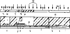
Fig. 2 is the cutaway view of structure of the tft active matrix substrate of the embodiment of the invention 1.
Fig. 3 is the plane graph of the rectangular configuration status of tft active matrix substrate of the embodiment of the invention 1.
Fig. 4 is the cutaway view of the tft active matrix substrate manufacturing process of the embodiment of the invention 1.
Fig. 5 is the cutaway view of the tft active matrix substrate manufacturing process of the embodiment of the invention 1.
Fig. 6 is the cutaway view of the tft active matrix substrate manufacturing process of the embodiment of the invention 1.
Fig. 7 is the cutaway view of the tft active matrix substrate manufacturing process of the embodiment of the invention 1.
Fig. 8 is the cutaway view of the tft active matrix substrate manufacturing process of the embodiment of the invention 1.
Fig. 9 is the cutaway view of the tft active matrix substrate manufacturing process of the embodiment of the invention 1.
Figure 10 is the cutaway view of the tft active matrix substrate manufacturing process of the embodiment of the invention 1.
Figure 11 is the cutaway view of the tft active matrix substrate manufacturing process of the embodiment of the invention 1.
Figure 12 is the cutaway view of the tft active matrix substrate manufacturing process of the embodiment of the invention 1.
Figure 13 is the cutaway view of the tft active matrix substrate manufacturing process of the embodiment of the invention 1.
Figure 14 is the cutaway view of the tft active matrix substrate manufacturing process of the embodiment of the invention 1.
Figure 15 is the plane graph of the tft active matrix substrate manufacturing process of the embodiment of the invention 1.
Figure 16 is the plane graph of the tft active matrix substrate manufacturing process of the embodiment of the invention 1.
Figure 17 is the plane graph of the tft active matrix substrate manufacturing process of the embodiment of the invention 1.
Figure 18 is the plane graph of the tft active matrix substrate manufacturing process of the embodiment of the invention 1.
Figure 19 is the plane graph of the tft active matrix substrate manufacturing process of the embodiment of the invention 1.
Figure 20 is the perspective view of TFT structural portion.
Figure 21 has formed the conductivity perspective view of the TFT structural portion of attachment again.
Figure 22 is the plane graph of the tft active matrix substrate manufacturing process variation of the embodiment of the invention 1.
Figure 23 is the plane graph of structure of the tft active matrix substrate of the embodiment of the invention 2.
Figure 24 is the cutaway view of structure of the tft active matrix substrate of the embodiment of the invention 2.
Figure 25 is the cutaway view of the tft active matrix substrate manufacturing process of the embodiment of the invention 2.
Figure 26 is the cutaway view of the tft active matrix substrate manufacturing process of the embodiment of the invention 2.
Figure 27 is the cutaway view of the tft active matrix substrate manufacturing process of the embodiment of the invention 2.
Figure 28 is the cutaway view of the tft active matrix substrate manufacturing process of the embodiment of the invention 2.
Figure 29 is the cutaway view of the tft active matrix substrate manufacturing process of the embodiment of the invention 2.
Figure 30 is the cutaway view of the tft active matrix substrate manufacturing process of the embodiment of the invention 2.
Figure 31 is the cutaway view of the tft active matrix substrate manufacturing process of the embodiment of the invention 2.
Figure 32 is the cutaway view of the tft active matrix substrate manufacturing process of the embodiment of the invention 2.
Figure 33 is the cutaway view of the tft active matrix substrate manufacturing process of the embodiment of the invention 2.
Figure 34 is the cutaway view of the tft active matrix substrate manufacturing process of the embodiment of the invention 2.
Figure 35 is the cutaway view of the tft active matrix substrate manufacturing process of the embodiment of the invention 2.
Figure 36 is the cutaway view of the tft active matrix substrate manufacturing process of the embodiment of the invention 2.
Figure 37 is the cutaway view of the tft active matrix substrate manufacturing process of the embodiment of the invention 2.
Figure 38 is the cutaway view of the tft active matrix substrate manufacturing process of the embodiment of the invention 2.
Figure 39 is the cutaway view of the tft active matrix substrate manufacturing process of the embodiment of the invention 2.
Figure 40 is the plane graph of the tft active matrix substrate manufacturing process of the embodiment of the invention 2.
Figure 41 is the plane graph of the tft active matrix substrate manufacturing process of the embodiment of the invention 2.
Figure 42 is the plane graph of the tft active matrix substrate manufacturing process of the embodiment of the invention 2.
Figure 43 is the plane graph of the tft active matrix substrate manufacturing process of the embodiment of the invention 2.
Figure 44 is the plane graph of the tft active matrix substrate manufacturing process of the embodiment of the invention 2.
Figure 45 is the plane graph of the tft active matrix substrate manufacturing process of the embodiment of the invention 2.
Figure 46 is the plane graph of the tft active matrix substrate manufacturing process of the embodiment of the invention 2.
(symbol description)
4 grid wirings, 6 semiconductor films, 7 ohmic contact films, 8 second metallic films, 23 peristomes, 24 source wiring, 26 drain electrode wirings, 27TFT groove, 30 pixel electrodes, AR active region layer, RP1, RP2 photoresist pattern.
Embodiment
<A. embodiment 1 〉
<A-1. apparatus structure 〉
As the Eletro-optical display apparatus of the embodiment of the invention 1, at Fig. 1 the planar structure as the tft active matrix substrate 100 of the transmissive liquid crystal display device of switch element with TFT is shown, and, at Fig. 2 the cross-section structure on the A-O-A ' line among Fig. 1 is shown.
Fig. 1 is the plane graph of a pixel on the expression tft active matrix substrate 100, on the tft active matrix substrate 100, and a plurality of such picture element matrix shape configurations.
As shown in Figure 1, on transparent insulating substrate such as glass substrate 1, dispose the grid wiring 4 that its part constitutes gate electrode 2.Grid wiring 4 is configured to unidirectional linearity and extends on transparent insulating substrate 1, this direction is called directions X here, and planar the direction with the directions X quadrature is called the Y direction.
In addition, with the auxiliary capacitance electrode 3 that grid wiring 4 extends abreast across arranged spaced and grid wiring 4, determine the Y direction size of pixel electrodes 30 by grid wiring 4 and auxiliary capacitance electrode 3.
In addition, above grid wiring 4 and auxiliary capacitance electrode 3, be provided with linearity semiconductor multilayer film SL orthogonally with both.Stacked ohmic contact film 7 on the semiconductor film 6 among the semiconductor multilayer film SL, it is a plurality of across arranged spaced that semiconductor multilayer film SL extends ground in the Y direction, determined the directions X size of pixel electrode 30 by adjacent semiconductor multilayer film SL.Also has not configuration overlappingly above auxiliary capacitance electrode 31 of semiconductor multilayer film SL.
Semiconductor multilayer film SL is set as and is included in and the cross part branch of grid wiring 4 and the part of extending along grid wiring 4, and wherein semiconductor film 6 parts constitute the active area layer AR of TFT.
In addition, semiconductor multilayer film SL top is provided with linearity source wiring 25 along semiconductor multilayer film SL.Source wiring 25 is same with semiconductor multilayer film SL, is included in and the cross part branch of grid wiring 4 and the part of extending along grid wiring 4, and this part constitutes the source electrode 24 of TFT.Also have, there is ohmic contact film 7 in electrode 24 lower floors in source.
In addition, drain electrode 26 is configured to begin to extend to from active region layer AR transparent insulating substrate 1 top of pixel electrode 30 belows.Drain electrode 26 is included in the part of extending along directions X along the end edge portion below of the directions X of pixel electrode 30.
Also have, on the layer AR of active region, source electrode 24 and drain electrode 26 are across establishing at interval, and semiconductor film 6 between the two becomes TFT groove 27.In addition, on the position parallel, be provided with the pixel drain contact hole 29 that reaches pixel electrode 30 with the TFT groove 27 of drain electrode 26.
The cross-section structure of tft active matrix substrate 100 then, is described by Fig. 2.
As shown in Figure 2, on transparent insulating substrate 1, disposed gate electrode 2 (grid wiring 4) and auxiliary capacitance electrode 3, can cover comprise that gate electrode 2 (grid wiring 4) is gone up and auxiliary capacitance electrode 3 on whole transparent insulating substrate 1 on disposed first dielectric film 5.Also have, first dielectric film 5 works as gate insulating film on gate electrode 2 positive tops.
On first dielectric film 5, dispose semiconductor film 6, on semiconductor film 6, dispose ohmic contact film 7.Also have, become in the semiconductor film 6 on the part of TFT groove 27 and do not dispose ohmic contact film 7.
In addition, in ohmic contact film 7 tops configuration source wiring 25, but ohmic contact film 7 tops among the layer AR of active region are divided into the part and the part that has disposed drain electrode 26, two parts sandwich TFT groove 27 that has disposed source electrode 24.
Also have, drain electrode 26 extends to semiconductor film side and first dielectric film, 5 tops from ohmic contact film 7 tops.
Then, second dielectric film 28 is configured to cover whole transparent insulating substrate 1 end face that comprises on source wiring 25, source electrode 24 and the drain electrode 26, disposes pixel electrode 30 on second dielectric film 28.
Fig. 3 is the plane graph of a plurality of pixels of representing matrix shape configuration, and the grid wiring 4 of neighbor and auxiliary capacitance electrode 3 are disposed across the interval overlappingly.
<A-2. manufacture method 〉
Then, be Fig. 4~Figure 14 by the cutaway view of representing manufacturing process successively, describe with regard to the manufacture method of tft active matrix substrate 100.Also have, the section of Fig. 4~shown in Figure 14 is corresponding to the section on the A-O-A ' line among Fig. 1.In addition, the plane graph of each operation shown in Figure 15~Figure 19.
At first, in the operation shown in Figure 4, on the transparent insulating substrate 1 of glass substrate etc. film forming first metallic film (not shown) afterwards, through the operation of photomechanical process for the first time, to major general's gate electrode 2, auxiliary capacitance electrode 3 and grid wiring 4 patternings.
Here, preferably adopt the low Al of resistivity (aluminium) or Mo (molybdenum) as first metallic film or be the alloy of principal component with them.
Best manufacture method when adopting Mo as first metallic film is by adopting the known sputtering method of argon (Ar) gas, with the Mo film with 200nm thickness film forming.
At this moment sputter condition is to use DC magnetron sputter reactor mode, and the film forming power density is 3W/cm
2, the Ar gas flow is 40sccm.
Also have, in above-mentioned photomechanical process first time operation, form the photoresist pattern, and by adopting sulphur hexafluoride sulphur (SF
6) gas+oxygen (O
2) the known dry ecthing method of mist of gas is the etching of Mo film.This moment, the etching speed of Mo film was about 200nm/ minute.
Then, remove the photoresist pattern, obtain gate electrode 2, auxiliary capacitance electrode 3 and grid wiring 4.
Figure 15 is the plane graph of gate electrode 2, auxiliary capacitance electrode 3 and the grid wiring 4 of formation on transparent insulating substrate 1.
Then, in operation shown in Figure 5, cover whole transparent insulating substrate 1 end face ground and form first dielectric film 5, behind covering grid electrode 2 (grid wiring 4) and auxiliary capacitance electrode 3, film forming semiconductor film 6 on first dielectric film 5, and film forming ohmic contact film 7 thereon.
Then, through the operation of photomechanical process for the second time, with semiconductor film 6 and ohmic contact film 7 patternings.At this moment, determine to form the active region layer AR of TFT with linearity semiconductor multilayer film SL.
In addition, during with semiconductor film 6 and ohmic contact film 7 patternings, semiconductor film 6 and ohmic contact film 7 are not extended to form on the pixel display area of pixel electrode 30 (Fig. 2) afterwards.
Best manufacture method as semiconductor film 6 and ohmic contact film 7 is used chemical vapor-phase growing (CVD) method, the silicon nitride film (SiNx:x is a positive number) that forms about 400nm thickness is as first dielectric film 5, and amorphous silicon (a-Si) film that forms about 150nm thickness is as semiconductor film 6, and form about 50nm thickness with the n of phosphorus (P) as the impurity interpolation
+Amorphous silicon (n
+A-Si) film is as ohmic contact film 7.
Also have, in above-mentioned photomechanical process second time operation, form the photoresist pattern, by adopting sulphur hexafluoride sulphur (SF
6) the known dry ecthing method of mist of gas+chlorine (HCl) gas+helium (He), with semiconductor film 6 (a-Si film) and ohmic contact film 7 (n
+The a-Si film) etching.The etching speed of this moment is about 300nm/ minute.
Then, remove the photoresist pattern, obtain linearity semiconductor multilayer film SL, obtain active region layer AR simultaneously.Figure 16 forms semiconductor multilayer film SL and active region layer AR to make its part overlapping plane graph on gate electrode 2, grid wiring 4 and auxiliary capacitance electrode 3.
Then, in operation shown in Figure 6, cover whole transparent insulating substrate 1 end face ground film forming second metallic film 8.
Here, the best manufacture method when adopting Mo as second metallic film 8 is by adopting the known sputtering method of Ar gas, with Mo film film forming 200nm thickness.
At this moment sputter condition is to use DC magnetron sputter reactor mode, and the film forming power density is 3W/cm
2, the Ar gas flow is 40sccm.
Then, in the operation of Fig. 7~shown in Figure 9, cover whole second metallic film 8 end face ground and form photoresist 9,, carry out the patterning of photoresist 9 through photomechanical process operation for the third time.
At first, in operation shown in Figure 7,, after about 90 seconds, utilize photomask R10 to carry out first exposure 120 ℃ of temperature prebakes with the about 1.6 μ m thickness of eurymeric photoresist 9 coatings of spin-coating method with the phenolic resins class.
Photomask R10 comprises the shading region 11 that district 12 and the light 13 that will expose interdicts fully that sees through that makes that exposure light 13 sees through fully, by first exposure, and the non-exposed area 14 that at first on photoresist 9, forms the exposure region 15 that exposes fully and do not have fully to expose.
Then, in operation shown in Figure 8, utilize photomask R16 to carry out second exposure.Among the photomask R16, have only the zone corresponding with the groove of TFT just to become and make seeing through of exposure light transmission distinguish 17, zone in addition becomes the shading region 16 that does not see through exposure light fully.
Then, in second exposure, photoresist 9 and not exclusively exposure, and expose with the exposure light 18 of first about 20~40% intensity of exposing, so that the part of exposure is residual with thin thickness after development, be so-called half exposure, on photoresist 9, form half exposure region 19.
As mentioned above, photoresist 9 is carried out after the two-stage exposure, develop with organic bases developer solution, by carrying out about 180 seconds back baking at 120 ℃, as shown in Figure 9, form the first thickness part 20 (raceway groove corresponding portion) corresponding with the groove of TFT, than the thick second thickness part 21 of this first thickness part 20 and compare the photoresist pattern RP1 that the 3rd thick thickness part 22 of the second thickness part 21 etc. has different thickness more than three kinds at least.
Also have, the thickness that the thick film that the thickness that an example of each several part thickness is the first thickness part 20 is about 0.4 μ m, the second thickness part 21 is about 1.4 μ m, the 3rd thickness part 22 is about 1.6 μ m (or more than 1.6 μ m).
Also have, the second thickness part 21 forms on semiconductor multilayer film SL and active region layer AR, the 3rd thickness part 22 after form on the zone of pixel electrode 30 (Fig. 2) and form.
Then, in operation shown in Figure 10, be mask with photoresist pattern RP1, carry out the etching of second metallic film 8.Here, by adopting SF
6Gas+O
2The known dry ecthing method of the mist of gas carries out etching.
Figure 17 be from semiconductor multilayer film SL and active region layer AR begin to after form pixel electrode 30 (Fig. 2) whole zone form the plane graph of second metallic film 8.Also have, omitted description among Figure 17, but obviously had photoresist pattern RP1 on second metallic film, 8 tops to photoresist pattern RP1.
Then, in operation shown in Figure 11, by utilizing the known photoresist ashing of oxygen plasma, remove the first thickness part 20 of photoresist pattern RP1, and on the second thickness part 21 and the 3rd thickness part 22 residual photoresist pattern RP1 and with all thinnings, thereby form the photoresist pattern RP2 that the part corresponding with the groove 27 (Fig. 2) of TFT becomes peristome 23.
At this moment, along with all filmings, as shown in figure 11, the relative photoresist pattern RP1 little of photoresist pattern RP2 in-plane size (profile) is enclosed the land set the photoresist ashing condition.
Then, in operation shown in Figure 12,, remove second metallic film 8, ohmic contact film 7 successively by etching via the peristome 23 of photoresist pattern RP2.
Here, as the optimal etch method of these films, use SF
6Gas+O
2The known dry ecthing method of the mist of gas, its etching speed all were made as on any film 200~300nm/ minute.Thus, second metallic film 8 and ohmic contact film 7 all are removed with same etch speed, these films can be unified etching much the samely.
Also have, second metallic film 8 with etched patternization becomes source wiring 25, and become source electrode 24 and drain electrode 26 on the layer AR of active region on semiconductor multilayer film SL.In addition, drain electrode 26 is patterned to after active region layer AR begins to extend to and forms on the zone of pixel electrode 30 (Fig. 2).
Then, by removing photoresist pattern RP2, as shown in figure 13, configuration source wiring 25 on semiconductor multilayer film SL, source of configuration electrode 24 and drain electrode 26 on the layer AR of active region.Between source electrode 24 and drain electrode 26, become the zone of exposing semiconductor film 6.This zone becomes the groove 27 of TFT.
Also have, photoresist pattern RP2 compares with photoresist pattern RP1, the little circle of its profile, therefore form the profile of the profile of second metallic film 8 of source electrode 24, source wiring 25 and drain electrode 26 and ohmic contact film 7 less than lower floor's semiconductor film 6, when the top is watched, source wiring 25 and source electrode 24 end faces are configured in the position that any end face of relative semiconductor film 6 is stepped back, and active region layer AR goes up drain electrode 26 end faces and also be configured in relative semiconductor film 6 and have the position that the end face of almost parallel relation is stepped back.Also have, above-mentioned almost parallel is meant that drain electrode 26 end faces are not limited to carry out patterning abreast with semiconductor film 6 end faces, also estimates at the situation that the relative semiconductor film of drain electrode 26 end faces 6 end slope ground form.Also have, also occur same phenomenon on source electrode 24 and source wiring 25 end faces.
Figure 18 is the plane graph of source wiring 25, source electrode 24 and drain electrode 26.As shown in figure 18, source electrode 24 has the linearity shape that extends to from source wiring 25 branches on the layer AR of active region, and drain electrode 26 is provided with the linearity part of extending along grid wiring 4.
Also have, employing Mo film more than has been described as second metallic film 8, and by adopting fluorine type gas (SF
6+ O
2Mist) dry ecthing method carries out etched operation, but metallic film material or etching work procedure are not limited to this, for example can adopt Ti as second metallic film 8, and can adopt the engraving method of fluoric acid+nitrose etching solution.
Then, in operation shown in Figure 14, after forming second dielectric film 28 and covering whole transparent insulating substrate 1 end face, with 4 photomechanical process operations, after form the pixel drain contact hole 29 that formation in the zone of pixel electrode 30 (Fig. 2) reaches drain electrode 26 surfaces at least.
More specifically say, use chemical vapor-phase growing (CVD) method, the silicon nitride film (SiNx:x is a positive number) that forms about 300nm thickness is as second dielectric film 28, then in above-mentioned the 4th photomechanical process operation, forming its part that forms pixel drain contact hole 29 becomes the photoresist pattern of peristome, by utilizing the known dry ecthing method of fluorine type gas to carry out the etching of second dielectric film 28, form the pixel drain contact hole 29 that reaches drain electrode 26 surfaces.
Mode with plane graph among Figure 19 is illustrated in the state that forms pixel drain contact hole 29 on the drain electrode 26, but has suitably omitted the description to second dielectric film 28.
At last, the film forming transparent conducting film is with after covering whole transparent insulating substrate 1 end face, with the 5th photomechanical process operation, the pixel electrode 30 that formation is electrically connected with the drain electrode 26 of lower floor via pixel drain contact hole 29, thus can access the tft active matrix substrate 100 of the cross-section structure that has as shown in Figure 2.
More specifically say, by utilizing Ar gas known sputtering method, with indium oxide (In
2O
3) and tin oxide (SnO
2) behind the ITO film film forming 100nm thickness that mixes, in above-mentioned the 5th photomechanical process operation, the part that forms pixel electrode 30 is comprised the known wet etch method of the solution of hydrochloric acid+nitric acid by the photoresist pattern that photoresist covers by utilization, remove the ITO film, form pixel electrode 30.
The action effect of<A-3. feature 〉
In the tft active matrix substrate 100 of the embodiment of the invention 1 of above explanation, form source wiring 25, when source electrode 24 and drain electrode 26, at first, pattern RP1 removes second metallic film 8 that does not need part with photoresist, use photoresist pattern RP2 then with RP1 ashing of photoresist pattern and filming, with source wiring 25, source electrode 24 and drain electrode 26 patternings, simultaneously with TFT groove patterning, therefore photomechanical process operation that can be enough 3 times forms by gate electrode 2, gate insulating film 5, active region layer AR, the TFT structural portion that source electrode 24 and drain electrode 26 constitute can be simplified manufacturing process.
In addition, utilize photoresist pattern RP1, removing to cover in larger area second metallic film 8 does not need part, via the peristome 23 of photoresist pattern RP2, removes second metallic film 8 successively and ohmic contact film 7 forms TFT groove 27 by etching.
Therefore, be semiconductor film 6 and n with relative a-Si film
+The a-Si film be that metal film that ohmic contact film 7 does not have an etching selectivity is when forming second metallic film 8, or use when not having the etching work procedure of etching selectivity, can well control and remove second metallic film 8 and ohmic contact film 7, and can accurately control semiconductor film 6 thickness that constitute TFT groove 27, therefore and can suppress its deviation, can prevent that deviation because of the TFT characteristic from causing the irregular situation of demonstration of liquid crystal indicator.Also have, the occasion that this is not limited to semiconductor film 6 and the amorphous Si film of ohmic contact film 7 employings also can obtain same effect when adopting polysilicon.
Also have, when forming photoresist pattern RP1, by carrying out half exposure, can form and not exclusively remove the zone of photoresist material, by should the zone as the zone corresponding with the groove of TFT, remove this part with the ashing mode, and other parts are terminated in filming, can make photoresist pattern RP2 in-plane size (profile) than the little circle of photoresist pattern RP1.
In addition, by utilizing the etching of photoresist pattern RP2, make formation source electrode 24, second metallic film 8 of source wiring 25 and drain electrode 26 and the profile of ohmic contact film 7 are less than the profile of semiconductor film pattern 6, from above when watching, the position that any end face that can make source wiring 25 and source electrode 24 end faces be positioned at relative semiconductor film 6 is stepped back, and can make active region layer AR go up drain electrode 26 end faces also to be arranged in the position that end face that relative semiconductor film 6 is in the almost parallel relation is stepped back, therefore when second metallic film 8 and 7 dry ecthings of ohmic contact film, even if the material that constitutes these films is attached to the occasion of etching face again as conductive material, also can prevent source electrode 24 and drain electrode 26 conducting by conductive material.Also have, above-mentioned almost parallel is meant that drain electrode 26 end faces are not limited to carry out patterning abreast with semiconductor film 6 end faces, also estimates at the situation that the relative semiconductor film of drain electrode 26 end faces 6 end slope ground form.Also have, also occur same phenomenon on source electrode 24 and source wiring 25 end faces.
About this effect, further specify by Figure 20 and Figure 21.
Figure 20 and Figure 21 are the perspective views of structure that expression comprises the TFT structural portion of active region layer AR, do not form the conductivity state of attachment again shown in Figure 20, have formed the conductivity state of attachment CR again shown in Figure 21.
As shown in figure 21, the conductivity that when second metallic film 8 and 7 dry ecthings of ohmic contact film, generates again attachment CR major sedimentary at the end edge portion of semiconductor film 6, crystallizing field on the interarea of semiconductor film 6 is about 0.2 μ m from the length of semiconductor film 6 end faces, deposits along semiconductor film 6 end edge portions.Also have, 0.2 above-mentioned μ m is a mean value, is actually since about 0.1 μ m to be to the maximum about 0.3 μ m.
Also have, the thickness of semiconductor film 6 is about 150nm (0.15 μ m), roughly whole of semiconductor film 6 end faces by conductivity again attachment CR cover.
Deposited this conductivity again during attachment CR at the end edge portion of semiconductor film 6, if the ohmic contact film 7 of source electrode 24, drain electrode 26 and their lower floor extends near the position of semiconductor film 6 end faces, then conductivity again attachment CR become the electric current leakage path, source electrode 24 and drain electrode 26 are conducted, and the leakage current when possible TFT ends becomes big.
But, in the tft active matrix substrate 100 of the embodiment of the invention 1, with above-mentioned ashing condition enactment is that photoresist pattern RP2 endface position is stepped back more than the 0.3 μ m at the corresponding end face of relative photoresist pattern RP1 on the in-plane, and utilize this photoresist pattern RP2, with second metallic film 8 and ohmic contact film 7 patternings, the profile of ohmic contact film 7 that therefore can make source electrode 24, source wiring 25, drain electrode 26 and their lower floors is less than the profile of semiconductor film 6.
Therefore, even if on semiconductor film 6 end edge portions, deposited the conductivity occasion of attachment CR more as shown in figure 21, the ohmic contact film 7 that also prevents source electrode 24, drain electrode 26 and their lower floors and conductivity attachment CR again contact, thus can prevent conductivity again attachment CR become the electric current leakage path and situation that source electrode 24 and drain electrode 26 are conducted.
Also have, as above explanation the thickness of the first thickness part 20 of photoresist pattern RP1 is made as about 0.4 μ m, but this is a controlled value of considering half exposure, also is simultaneously the value of considering the set back distance of above-mentioned photoresist pattern RP2 end face.
Promptly, the first thickness part 20 is removed fully by the ashing that utilizes oxygen plasma, but set in this podzolic process roughly isotropically and the roughly the same condition of the ashing speed on any position, thereby photoresist pattern RP2 end face is by the about 0.4 μ m of ashing, as a result, the relative photoresist pattern of photoresist pattern RP2 end face RP1 steps back about 0.4 μ m.This value is greater than the conductivity Breadth Maximum 0.3 μ m of attachment CR again, therefore can reliably prevent by the conductivity electric current leakage path that forms of attachment CR again.
Like this, have and to set the advantage of the set back distance of photoresist pattern P R2 end face by the thickness of the first thickness part 20 by carrying out isotropic ashing.
In addition, in the tft active matrix substrate 100 of the embodiment of the invention 1, as explanation by Fig. 5, semiconductor film 6 and ohmic contact film 7 are extended on the pixel display area that pixel electrode 30 forms carry out patterning, therefore do not have semiconductor film 6 and ohmic contact film 7 in drain electrode 26 bottoms that extend to pixel display area.Therefore, be mapped to when using tft active matrix substrate 100 in the transmissive liquid crystal display device of pixel display area in backlight illumination, it is semiconductor film 6 that light can not shine the a-Si film, therefore can suppress light activated electric current generation, thereby can prevent the deterioration of the cut-off characteristics of TFT.
<A-4. variation 〉
As explanation by Fig. 7 and Fig. 8, form the example of photoresist pattern RP1 with the two-stage exposure shown in the embodiment 1, but be not limited to this, available single exposure forms photoresist pattern RP1.
Promptly, as shown in figure 22, the part corresponding with half exposure region 19 becomes its exposure light transmission amount and is about 20~40% semi-transparent mistake district 34, and can adopt to utilize to have the photomask R31 that sees through the shading region 32 that district 33 and the light that will expose interdicts fully that makes that exposure light sees through fully the method that phenolic resins class eurymeric photoresist 9 is exposed.
(transit dose of the light 13 of 350nm~450nm) is reduced to about about 20~40% filter plate film to the wave band of the photomask R31 that is provided with semi-transparent mistake district 34 by will being used to expose usually, be formed on the position corresponding with semi-transparent mistake district 34, perhaps semi-transparent mistake district 34 is made the pattern of finedraw opening shape, thereby utilize light diffraction ground to form.When having utilized this photomask R31 that is provided with semi-transparent mistake district 34, form the photoresist pattern RP1 that comprises first~the 3rd thickness part 20,21,22 shown in Figure 9 in the lump with 1 exposure, therefore can simplify the photomechanical process operation.
<B. embodiment 2 〉
<B-1. apparatus structure 〉
Eletro-optical display apparatus as the embodiment of the invention 2, illustrate at Figure 23 and to possess the planar structure as the tft active matrix substrate 200 of the emissive type organic EL display of organic electroluminescent (EL) element of switch element TFT, and the cross-section structure of B-O-B ' line among Figure 23 shown in Figure 24.
Figure 23 is the plane graph of a pixel on the expression tft active matrix substrate 200, a plurality of such pixels of rectangular configuration on the tft active matrix substrate 200.Also have, in Figure 23 and Figure 24, for adopting prosign, and omit repeat specification with tft active matrix substrate 100 same structures illustrated in figures 1 and 2.
As shown in figure 23, on transparent insulating substrate such as glass substrate 1, dispose the grid wiring 4 that its part constitutes gate electrode 2.Grid wiring 4 unidirectional linearity on transparent insulating substrate 1 is extended the ground configuration, this direction is called directions X here, and planar the direction with the directions X quadrature is called the Y direction.
In addition, above grid wiring 4, make both be provided with linearity semiconductor multilayer film SL orthogonally.Semiconductor multilayer film SL is stacked ohmic contact film 7 on semiconductor film 6, and it is a plurality of across arranged spaced that semiconductor multilayer film SL extends ground in the Y direction, and determines the size of pixel region 40 at directions X by adjacent semiconductor stacked film SL.
Semiconductor multilayer film SL is provided with not only along the Y direction and extends, and with the cross part branch of grid wiring 4 and the part of extending along grid wiring 4, wherein semiconductor film 6 parts constitute the active region layer AR of TFT.
In addition, be provided with linearity source wiring 25 on semiconductor multilayer film SL top along semiconductor multilayer film SL.Source wiring 25 and semiconductor multilayer film SL be provided with equally with the cross part branch of grid wiring 4 and the part of extending along grid wiring 4, this part becomes TFT source electrode 24.Also have, there is ohmic contact film 7 in 24 lower floors at the source electrode.
In addition, begin to cover transparent insulating substrate 1 top, positive electrode 38 (pixel electrode) below from active region layer AR and extend ground configuration drain electrode 26A.
Also have, on the layer AR of active region, source electrode 24 and drain electrode 26A are across establishing at interval, and semiconductor film 6 between the two becomes TFT groove 27.In addition, on the position parallel, be provided with the anode drain contact hole 29A that reaches positive electrode 38 with the TFT groove 27 of drain electrode 26.
In addition, can surround pixel region 40 ground frame 41 is set.Setting has the electroluminescence layer 42 than the zone of the big circle of frame 41 end edge portions, is provided with the positive electrode 38 that comprises than the zone of electroluminescence layer 42 big circles in electroluminescence layer 42 bottoms.Also have, on a plurality of viewing area of picture element matrix shape configuration, negative electrode is set comprehensively, in addition, be provided with the packaging part of inert gases such as encapsulating Ar or nitrogen etc., but omitted the diagram of this part.
Then, by Figure 24, describe with regard to the cross-section structure of tft active matrix substrate 200.
As shown in figure 24, configuration gate electrode 2 (grid wiring 4) on transparent insulating substrate 1, covering comprises gate electrode 2 (grid wiring 4) end face at interior whole transparent insulating substrate 1 end face ground configuration first dielectric film 5.Also have, first dielectric film 5 is working as gate insulating film on the part directly over the gate electrode 2.
Configuring semiconductor film 6 on first dielectric film 5, configuration ohmic contact film 7 on semiconductor film 6.The part that becomes TFT groove 27 in semiconductor film 6 is not established ohmic contact film 7 in addition.
In addition, in ohmic contact film 7 tops configuration source wiring 25, but ohmic contact film 7 tops among the layer AR of active region are divided into the part and the part that has disposed drain electrode 26, these two part sandwich TFT grooves 27 that has disposed source electrode 24.
Also have, drain electrode 26 begins to extend to semiconductor film 6 sides and first dielectric film, 5 tops from ohmic contact film 7 tops.
Dispose second dielectric film 28, cover whole transparent insulating substrate 1 end face that comprises source wiring 25, source electrode 24 and drain electrode 26A end face.
In addition, can cover the layer insulation thickness 36 that whole second dielectric film 28 end face ground configurations is made of the photonasty organic resin film, and be provided with and connect interlayer dielectric 36 and second dielectric film 28 and reach anode drain contact hole 29A on the drain electrode 26A.
Then, configuration reflectance coating 38a covers the part corresponding with the pixel region 40 of interlayer dielectric 36, and covering anode drain contact hole 29A inner face and contacting with drain electrode 26A.Also have, configuration ITO film 38b constitutes positive electrode 38 by reflectance coating 38a and ITO film 38b on reflectance coating 38a.
In addition, can surround the frame layer 41 that pixel region 40 ground settings are made of organic resin, the part corresponding with pixel region 40 becomes peristome 50.Also have, frame layer 41 becomes tabular surface ground and is provided with on the interlayer dielectric between the neighbor 36.
Then,, in addition, the tabular surface that negative electrode 43 covers frame layers 41 is set, covers peristome 50 inner faces simultaneously and contact with electroluminescence layer 42 at positive electrode 38 tops corresponding configuration electroluminescence layer 42 with peristome 50 bottom surface sections.
Then, comprise on a plurality of viewing area of the picture element matrix shape configuration of negative electrode 43, by in order to inert gas or N such as encapsulation Ar
2The packaging part 44 of gas etc. covers.Also have, packaging part 44 stops outside the viewing area, and negative electrode 43 is electrically connected with the earth terminal that is transfused to from the terminal connecting portion of the signal of outside outside being located at the viewing area.
<B-2. manufacture method 〉
Then, be Figure 25~Figure 39 by the cutaway view of representing manufacturing process successively, describe with regard to the manufacture method of tft active matrix substrate 200.Also have, the section of Figure 25~shown in Figure 39 is corresponding to the section of B-O-B ' line among Fig. 1.In addition, Figure 40~Figure 46 represents the plane graph in each operation.
At first, in operation shown in Figure 25, behind film forming first metallic film (not shown) on the transparent insulating substrate such as glass substrate 1, through the operation of photomechanical process for the first time, to major general's gate electrode 2 and grid wiring 4 patternings.Here, preferably adopt the low Al of resistivity value or Mo as first metallic film or be the alloy of principal component with them.Also have, the best manufacture method of first metallic film is identical with the method for explanation among the embodiment 1, therefore omits explanation.
Figure 40 is the gate electrode 2 of formation on transparent insulating substrate 1 and the plane graph of grid wiring 4.
Then, in operation shown in Figure 26, cover whole transparent insulating substrate 1 ground and form first dielectric film 5, behind covering grid electrode 2 (grid wiring 4), film forming semiconductor film 6 on first dielectric film 5, and film forming ohmic contact film 7 thereon.
Then, through the operation of photomechanical process for the second time, with semiconductor film 6 and ohmic contact film 7 patternings.At this moment, determine to form the active region layer AR of TFT with linearity semiconductor multilayer film SL.
The best manufacture method of semiconductor film 6 and ohmic contact film 7 is identical with the method for explanation among the embodiment 1, therefore omits explanation.
Figure 41 makes one form the plane graph of semiconductor multilayer film SL and active region layer AR on gate electrode 2 and grid wiring 4 with overlapping.
Then, in operation shown in Figure 27, cover whole transparent insulating substrate 1 end face ground film forming second metallic film 8.Also have, the best manufacture method of second metallic film 8 is identical with the method for explanation among the embodiment 1, therefore omits explanation.
Then, in the operation of Figure 28~shown in Figure 30, cover whole second metallic film 8 end face ground and form photoresist 9, through photomechanical process operation for the third time, with photoresist 9 patternings and form photoresist pattern RP1.Also have,, therefore omit explanation about the formation method of photoresist pattern RP1 is identical with the method that illustrates by Fig. 7~Fig. 9.
Then, in operation shown in Figure 31, be mask with photoresist pattern RP1, carry out the etching of second metallic film 8.Here, adopt SF
6Gas+O
2The known dry ecthing method of the mist of gas carries out etching.
Figure 42 be second metallic film 8 cover from semiconductor multilayer SL end face and active region layer AR end face to after form the regional end face of positive electrode 38 (Figure 24) and the plane graph that forms.Also have, the description of having omitted relevant photoresist pattern RP1 among Figure 42, but obviously have photoresist pattern RP1 on second metallic film, 8 tops.
Then, in operation shown in Figure 32, by utilizing the known photoresist ashing of oxygen plasma, remove the first thickness part 20 of photoresist pattern RP1, and on the second thickness part 21 and the 3rd thickness part 22 residual photoresist pattern RP1 and with all thinnings, thereby form the photoresist pattern RP2 that the part corresponding with the groove 27 (Figure 24) of TFT becomes peristome 23.
At this moment, along with all filmings, shown in figure 32, the relative photoresist pattern RP1 little of photoresist pattern RP2 in-plane size (profile) is enclosed the land set the photoresist ashing condition.
Then, in operation shown in Figure 33,, remove second metallic film 8, ohmic contact film 7 successively by etching via the peristome 23 of photoresist pattern RP2.About the optimal etch method of these films is identical with the method for explanation among the embodiment 1, therefore omit explanation.
Also have, come second metallic film 8 of patterning, on semiconductor multilayer film SL, become source wiring 25, on the layer AR of active region, become source electrode 24 and drain electrode 26A by etching.Also have, the patterned back of drain electrode 26A forms the regional end face of positive electrode electricity 38 (Figure 24) after active region layer AR begins to extend to.
Then, as shown in figure 34, by removing photoresist pattern RP2, configuration source wiring 25 on semiconductor multilayer film SL, source of configuration electrode 24 and drain electrode 26A on the layer AR of active region.
Photoresist pattern RP2 compares the little circle of its profile with photoresist pattern RP1, therefore form semiconductor film 6 profiles of the profile of second metallic film 8 of source electrode 24, source wiring 25 and drain electrode 26A and ohmic contact film 7 less than lower floor, when the top is watched, source wiring 25 and source electrode 24 end faces are configured in the position that any end face of relative semiconductor film 6 is stepped back, and active region layer AR goes up that drain electrode 26A end face is also configurable to have the position that the end face of almost parallel relation is stepped back at semiconductor film 6 relatively.Also have, above-mentioned almost parallel is meant that drain electrode 26A end face is not limited to carry out patterning abreast with semiconductor film 6 end faces, also estimates at the situation that the relative semiconductor film of drain electrode 26A end face 6 end slope ground form.Also have, also occur same phenomenon on source electrode 24 and source wiring 25 end faces.
Figure 43 is the plane graph of source wiring 25, source electrode 24 and drain electrode 26A.As shown in figure 43, source electrode 24 has the linearity shape that extends to from source wiring 25 branches on the layer AR of active region.
Then, in operation shown in Figure 35, after covering whole transparent insulating substrate 1 end face ground and forming second dielectric film 28, the interlayer dielectric 36 that coating is made of the photonasty organic resin film, with the 4th photomechanical process operation, form the contact hole 29A that penetrates into drain electrode 26A surface.
Also have,, therefore omit explanation about the best manufacture method of second dielectric film 28 is identical with the method for explanation among the embodiment 1.
As interlayer dielectric 36 best manufacture methods, with spin-coating method with the acrylic compounds photosensitive resin film, for example the ProductName PC335 of JSR (strain) system applies about 2 μ m thickness, forms by the 4th photomechanical process operation and connects the contact hole that interlayer dielectric 36 arrives second dielectric film, 28 surfaces.
And, utilize known fluorine type gas, second dielectric film, 28 etchings of this contact hole bottom surface are removed, thereby obtain arriving the anode drain contact hole 29A on drain electrode 26A surface.
On drain electrode 26A, form the plane graph of the state of anode drain contact hole 29A shown in Figure 44, but the description of having omitted relevant second dielectric film 28 for the purpose of convenient.
Then, in operation shown in Figure 36, cover whole transparent insulating substrate 1 end face ground film forming the 3rd metallic film (not shown), form positive electrode 38 at pixel region 40 (Figure 24) with the 5th photomechanical process operation.
Form the plane graph of the state of positive electrode 38 shown in Figure 45 in the part corresponding with pixel region 40.
Here, as the best manufacture method of the 3rd metallic film, utilizing known sputtering method film forming be the about 300nm thickness of reflectance coating 38a of the Al alloy formation of principal component with Al (aluminium), then, with sputtering method with the about 10nm thickness of noncrystalline ITO (a-ITO) film 38b film forming.
Then, form the photoresist pattern with above-mentioned the 5th photomechanical process operation, by etching with positive electrode 38 patternings.Also have, same with first and second metallic films of explanation before, this etching method can adopt known dry ecthing method, therefore but ITO film 38b can utilize the Al alloy that is made of known phosphoric acid+nitric acid+acetic acid to carry out etching with etching solution, also can adopt and utilize the solution that contains phosphoric acid+nitric acid+acetic acid with the ITO film 38b on the reflectance coating 38a of the Al of lower floor alloy and upper strata etching method in the lump simultaneously.
In addition, ITO film 38b except have can with lower reflecting film 38a simultaneously the etched in the lump advantage, work function has the value of comparing before and after the 4.0eV with the Al alloy up to about 5.0eV, therefore have the efficient of the holoe carrier that can improve the electroluminescence layer that injection is made of organic EL Material etc., and can improve the advantage of the luminous efficiency of organic EL display element.
Also have, ITO film 38b is an amorphous state, and is therefore different with docrystalline, almost not because of there is the concave-convex surface that causes in crystal boundary, thereby can prevent that to inject the bad luminous demonstration that causes bad because of the holoe carrier of concave-convex surface.
Have in for example available Ar gas of ITO film 38 of amorphous state of this advantage and add water (H
2O) sputtering method in the mist of gas forms.
In addition, replace ITO film 38b, can adopt indium oxide (In
2O
3) and the IZO film that mixes of zinc oxide (ZnO), perhaps the ITZO film of mixed oxidization zinc (ZnO) etc. in the ITO film.
IZO film or ITZO film can come etching with oxalic acid class etching solution, also can be etched in the etching solution but use at the Al alloy that contains known phosphoric acid+nitric acid+acetic acid, and therefore can be simultaneously etched in the lump with the reflectance coating 38a of lower floor.
Then, in operation shown in Figure 37, form the pixel region 40 (Figure 24) of usefulness for the organic EL layer of stipulating to become electroluminescence layer, at first, can cover whole transparent insulating substrate 1 end face ground coating and form the organic resin layer that constitutes by polyimides etc., by the 6th photomechanical process operation, form the frame layer 41 that the part corresponding with pixel region 40 becomes peristome 50.
The organic resin film that forms frame layer 41 preferably adopts the less polyimide-type materials of adsorption moisture that organic EL layer characteristic or reliability are exerted an influence.
As the best manufacture method of frame layer 41, the ProductName DL100 of TORAY INDUSTRIES system is applied about 2 μ m thickness, and utilize the 6th time above-mentioned photomechanical process operation, the frame layer 41 that will have the peristome 50 that reaches positive electrode 38 surfaces forms patterns.
Form the plane graph of state that the part corresponding with pixel region 40 is provided with the frame layer 41 of peristome 50 shown in Figure 46.
Then, in operation shown in Figure 38, positive electrode 38 surfaces of exposing in peristome 50 bottom surfaces form organic EL Material and obtain electroluminescence layer 42.
As the best manufacture method of electroluminescence layer 42, utilize known vapour deposition method, can obtain by on positive electrode 38, stacking gradually hole transmission layer, organic EL layer, electron transfer layer.
Here, hole transmission layer can be selected from organic widely class material such as known tri-arylamine group, aromatics hydrazone class, aromatics pyrazoline-substituting class, stilbene class, for example with N, N-biphenyl-N, N-two (3-aminomethyl phenyl)-1,1 '-biphenyl-4,4 ' diamines (TPD) etc. forms with 1~200nm thickness.
In addition, as organic EL layer, known dicyano methylene pyrans (emitting red light), cumarin (green emitting), quinacridine class (green emitting), tetraphenylbutadiene class (blue-light-emitting), talan benzene class materials such as (blue-light-emittings) are formed with 1~200nm thickness.
The material that to select from known derivative, triazole derivative, coumarin derivative etc. as electron transfer layer forms with 1~200nm thickness.
Also have in the above description, electroluminescence layer 42 adopts the structure that stacks gradually hole transmission layer, organic EL layer, electron transfer layer, but in order further to improve the luminous efficiency of electroluminescence layer, hole transmission layer can be made the double-layer structure of hole injection layer and hole transmission layer, and electron transfer layer be made the double-layer structure of electron transfer layer and electron injecting layer.
Then, in operation shown in Figure 39, can cover the transparent and electrically conductive film of the whole transparent insulating substrate 1 end face ground film forming ITO film that comprises peristome 50 inner faces etc., form negative electrode 43 with the 7th photomechanical process operation.
Negative electrode 43 can be seized electroluminescence layer 42 ground on both sides by the arms and form, and be connected with the electroluminescence layer 42 of lower floor in pixel region 40 as the opposite electrode of positive electrode 38.Also have, the interarea of negative electrode 43 preferably has high flatness.
As the best manufacture method of negative electrode 43, by in Ar gas, mixing H
2Carrying out sputter in the gas of O gas obtains noncrystalline shape a-ITO film with 100nm thickness film forming.
Then, after the photomechanical process operation forms the photoresist pattern, utilizes known oxalic acid class etching solution to carry out etching, remove the photoresist pattern and obtain negative electrode 43.
Also have,, can adopt IZO film or ITZO film, to replace the a-ITO film as negative electrode 43.
At last, for the decline of the display screen characteristics of luminescence that prevents to cause, will comprise the whole pixel display area of electroluminescence layer 42, with the inert gas or the N that have encapsulated as Ar because of moisture or impurity
2The packaging part 44 of gas etc. encapsulates, thereby can access the tft active matrix substrate 200 of the cross-section structure that has as shown in figure 24.
Also have, adopt transparent glass material as packaging part 44, the display screen outer peripheral portion formation sealant at tft active matrix substrate 200 encapsulates by crimping.
<B-3. characteristic action effect 〉
In the tft active matrix substrate 200 of the embodiment of the invention 2 of above explanation, available three times photomechanical process operation forms the TFT structural portion that is made of gate electrode 2, gate insulating film 5, active region layer AR, source electrode 24 and drain electrode 26A, can simplify manufacturing process.
In addition, utilize photoresist pattern RP1, remove cover larger area second metallic film 8 do not need part, via the peristome 23 of photoresist pattern P R2, remove second metallic film 8 and ohmic contact film 7 successively by etching, form TFT groove 27.
Therefore, be semiconductor film 6 and n with relative a-Si film
+The a-Si film be that metal film that ohmic contact film 7 does not have an etching selectivity is when forming second metallic film 8, when perhaps using the etching work procedure of no etching selectivity, can control well and remove second metallic film 8 and ohmic contact film 7, can accurately control semiconductor film 6 thickness that constitute TFT groove 27, therefore and can suppress its deviation, can prevent that the demonstration of the organic EL display that produces because of the TFT characteristic deviation is irregular.
In addition, by utilizing the etching of photoresist pattern RP2, make formation source electrode 24, second metallic film 8 of source wiring 25 and drain electrode 26A and the profile of ohmic contact film 7 are less than semiconductor film pattern 6 profiles, when the top is watched, source wiring 25 and source electrode 24 end faces can be configured in the position that any end face of relative semiconductor film 6 is all stepped back, and active region layer AR can be gone up drain electrode 26 end faces and also be configured in relative semiconductor film 6 and have the position that the end face of almost parallel relation is stepped back, therefore when second metallic film 8 and ohmic contact film 7 are carried out dry ecthing, even if the material that constitutes these films is attached to the occasion of etching face again as conductive material, also can prevent that source electrode 24 and drain electrode 26A from conducting by these conductive materials.
Claims (5)
1. Eletro-optical display apparatus, comprising the active matrix substrate, described active matrix substrate comprises: the insulating properties substrate, array-like disposes and is provided with a plurality of display pixels of the pixel electrode that is electrically connected with thin-film transistor on described insulating properties substrate, described thin-film transistor is scanned successively the grid wiring of selection, and supply with the source wiring of the signal of telecommunication, and overlook orthogonal thereto rectangular of described grid wiring and described source wiring to described pixel electrode;
Described thin-film transistor is provided with from the active region layer of the semiconductor film branch that is configured in described source wiring lower floor, and
The source electrode and the drain electrode that on the layer of described active region, dispose selectively across the interval,
On the layer of described active region, described at least source electrode is configured to make layer any endface position in the described relatively active region of its endface position to step back more than the preset distance,
Described drain electrode disposes from the ground, described insulating properties substrate top that described active region layer extends to pixel display area,
Described drain electrode lower floor in the described pixel display area is not provided with described active region layer.
2. Eletro-optical display apparatus as claimed in claim 1 is characterized in that: described preset distance is 0.3 μ m.
3. the manufacture method of an Eletro-optical display apparatus, described Eletro-optical display apparatus comprises active matrix substrate, described active matrix substrate comprises: the insulating properties substrate, array-like disposes and is provided with a plurality of display pixels of the pixel electrode that is electrically connected with thin-film transistor on described insulating properties substrate, described thin-film transistor is scanned successively the grid wiring of selection, and supply with the source wiring of the signal of telecommunication, and overlook orthogonal thereto rectangular of described grid wiring and described source wiring to described pixel electrode; The manufacture method of described Eletro-optical display apparatus comprises following operation:
(a) carrying out the photomechanical process first time behind film forming first conductive membrane on the described insulating properties substrate, with the operation of described grid wiring patterning;
(b) above the described grid wiring successively behind film forming dielectric film, semiconductor film and the ohmic contact film, carry out the photomechanical process second time, with described semiconductor film and described ohmic contact film patterning, form the lower membrane of described source wiring, and form from the operation of the active region layer of described semiconductor film branch; And
(c) afterwards in described operation (b), on whole of described insulating properties substrate behind film forming second conductive membrane, with the operation of the described second conductive membrane patterning,
Described operation (c) also comprises:
(c-1) carry out photomechanical process for the third time, on described second conductive membrane, formation extends to the described insulating properties substrate top of pixel display area from described lower membrane and described active region layer, and the operation of the first photoresist pattern that approaches with the corresponding relative other parts of the corresponding portion of raceway groove of the groove of described thin-film transistor;
(c-2) remove not by the operation of described second conductive membrane of the described first photoresist pattern covers by etching;
(c-3) afterwards, with the described first photoresist pattern ashing and filming, remove described raceway groove correspondence portion simultaneously, become the operation of the second photoresist pattern of peristome in described operation (c-2); And
(c-4) via the described peristome of the described second photoresist pattern, remove described second conductive membrane corresponding and described ohmic contact film successively by etching with described groove, remove successively not by described second conductive membrane of the described second photoresist pattern covers and described ohmic contact film by etching simultaneously, on the layer of described active region across at interval with source electrode and drain electrode patterning, simultaneously with the operation of described source wiring patterning.
4. the manufacture method of Eletro-optical display apparatus as claimed in claim 3 is characterized in that: described operation (c-3) comprises that roughly the same with the ashing speed of the ashing speed of the residual photoresist of described raceway groove correspondence portion and the described first photoresist pattern side is the operation that condition is carried out ashing.
5. the manufacture method of Eletro-optical display apparatus as claimed in claim 3 is characterized in that:
In the described operation (c-1), use the photoresist material of eurymeric photoresist as the described first photoresist pattern;
The exposure intensity that also comprises the described raceway groove correspondence portion that carries out the described first photoresist pattern is the operation of 20~40% half exposure of described other parts exposure intensity.
Applications Claiming Priority (2)
| Application Number | Priority Date | Filing Date | Title |
|---|---|---|---|
| JP2005176252A JP2006351844A (en) | 2005-06-16 | 2005-06-16 | Electro-optical display device and its manufacturing method |
| JP2005176252 | 2005-06-16 |
Publications (1)
| Publication Number | Publication Date |
|---|---|
| CN1881593A true CN1881593A (en) | 2006-12-20 |
Family
ID=37519703
Family Applications (1)
| Application Number | Title | Priority Date | Filing Date |
|---|---|---|---|
| CN 200610073326 Pending CN1881593A (en) | 2005-06-16 | 2006-03-28 | Electro-optical display device and method for manufacturing same |
Country Status (3)
| Country | Link |
|---|---|
| JP (1) | JP2006351844A (en) |
| CN (1) | CN1881593A (en) |
| TW (1) | TWI269449B (en) |
Cited By (1)
| Publication number | Priority date | Publication date | Assignee | Title |
|---|---|---|---|---|
| CN103529609A (en) * | 2012-07-04 | 2014-01-22 | 三菱电机株式会社 | Thin film transistor array substrate and liquid crystal display using the same |
Families Citing this family (8)
| Publication number | Priority date | Publication date | Assignee | Title |
|---|---|---|---|---|
| GB2448174B (en) * | 2007-04-04 | 2009-12-09 | Cambridge Display Tech Ltd | Organic thin film transistors |
| WO2009072451A1 (en) * | 2007-12-03 | 2009-06-11 | Semiconductor Energy Laboratory Co., Ltd. | Manufacturing method of thin film transistor and manufacturing method of display device |
| US8035107B2 (en) * | 2008-02-26 | 2011-10-11 | Semiconductor Energy Laboratory Co., Ltd. | Method for manufacturing display device |
| US7883943B2 (en) * | 2008-03-11 | 2011-02-08 | Semiconductor Energy Laboratory Co., Ltd. | Method for manufacturing thin film transistor and method for manufacturing display device |
| EP2180518B1 (en) * | 2008-10-24 | 2018-04-25 | Semiconductor Energy Laboratory Co, Ltd. | Method for manufacturing semiconductor device |
| US20120001179A1 (en) * | 2010-07-02 | 2012-01-05 | Semiconductor Energy Laboratory Co., Ltd. | Semiconductor device |
| US11215891B2 (en) * | 2019-05-24 | 2022-01-04 | Sharp Kabushiki Kaisha | Active matrix substrate and manufacturing method thereof |
| US20210028221A1 (en) * | 2019-07-26 | 2021-01-28 | Sharp Kabushiki Kaisha | Imaging panel |
Family Cites Families (2)
| Publication number | Priority date | Publication date | Assignee | Title |
|---|---|---|---|---|
| JP3208658B2 (en) * | 1997-03-27 | 2001-09-17 | 株式会社アドバンスト・ディスプレイ | Manufacturing method of electro-optical element |
| JP2001339072A (en) * | 2000-03-15 | 2001-12-07 | Advanced Display Inc | Liquid crystal display device |
-
2005
- 2005-06-16 JP JP2005176252A patent/JP2006351844A/en active Pending
- 2005-11-10 TW TW94139441A patent/TWI269449B/en not_active IP Right Cessation
-
2006
- 2006-03-28 CN CN 200610073326 patent/CN1881593A/en active Pending
Cited By (1)
| Publication number | Priority date | Publication date | Assignee | Title |
|---|---|---|---|---|
| CN103529609A (en) * | 2012-07-04 | 2014-01-22 | 三菱电机株式会社 | Thin film transistor array substrate and liquid crystal display using the same |
Also Published As
| Publication number | Publication date |
|---|---|
| JP2006351844A (en) | 2006-12-28 |
| TWI269449B (en) | 2006-12-21 |
| TW200701468A (en) | 2007-01-01 |
Similar Documents
| Publication | Publication Date | Title |
|---|---|---|
| CN1881593A (en) | Electro-optical display device and method for manufacturing same | |
| CN1761049A (en) | Thin film transistor array panel and manufacturing method thereof | |
| CN1248547C (en) | Organic electroluminescence display device and manufacturing method thereof | |
| CN100335959C (en) | Thin film transistor array substrate, method of fabricating the same, liquid crystal display panel having the same and fabricating method thereof | |
| CN1185909C (en) | Actively driven organic EL light emitting device and manufacturing method thereof | |
| CN1195243C (en) | Film transistor array panel for liquid crystal display and its producing method | |
| CN1293647C (en) | Semiconductor device and manufacturing method thereof | |
| CN1260695C (en) | Transistor array and active matrix substrate | |
| CN1808710A (en) | Thin film transistor array panel and method for manufacturing the same | |
| CN1447156A (en) | Wiring substrate for display device and its mfg. method | |
| CN1729719A (en) | Display device and manufacturing method of display device | |
| CN1646726A (en) | Vapor deposition method of low dielectric insulating film, thin film transistor using the same and preparation method thereof | |
| CN1437177A (en) | Organic Luminous display device | |
| CN1610859A (en) | Wiring structure, thin film transistor substrate using the wiring structure and manufacturing method thereof | |
| CN1508615A (en) | Electronic device, manufacturing method thereof, and sputtering target | |
| CN1848445A (en) | Light emitting device | |
| CN1961617A (en) | Organic electroluminescent device, process for fabricating the same and display | |
| CN101044627A (en) | Semiconductor device | |
| CN1409373A (en) | Stripping method and method for producing semiconductor device | |
| CN1378276A (en) | Wiring and wiring production method and wiring board and wiring board production method | |
| CN1685767A (en) | Laminated body, substrate with wiring, organic EL display element, connection terminal of organic EL display element, and manufacturing method thereof | |
| CN1655370A (en) | Display device and manufacturing method thereof | |
| CN1458640A (en) | Light emitting device and its producing method | |
| CN1607444A (en) | Thin film transistor array substrate and fabricating method thereof, liquid crystal display using the same and fabricating method thereof, and method of inspecting liquid crystal display | |
| CN1866548A (en) | Photoelectric conversion device, manufacturing method thereof and semiconductor device |
Legal Events
| Date | Code | Title | Description |
|---|---|---|---|
| C06 | Publication | ||
| PB01 | Publication | ||
| C10 | Entry into substantive examination | ||
| SE01 | Entry into force of request for substantive examination | ||
| AD01 | Patent right deemed abandoned | ||
| C20 | Patent right or utility model deemed to be abandoned or is abandoned |