CN1878042B - Orthogonal code synchronization system and method for spread spectrum CDMA communications - Google Patents
Orthogonal code synchronization system and method for spread spectrum CDMA communications Download PDFInfo
- Publication number
- CN1878042B CN1878042B CN200610099693XA CN200610099693A CN1878042B CN 1878042 B CN1878042 B CN 1878042B CN 200610099693X A CN200610099693X A CN 200610099693XA CN 200610099693 A CN200610099693 A CN 200610099693A CN 1878042 B CN1878042 B CN 1878042B
- Authority
- CN
- China
- Prior art keywords
- signal
- code
- base station
- spread
- spectrum
- Prior art date
- Legal status (The legal status is an assumption and is not a legal conclusion. Google has not performed a legal analysis and makes no representation as to the accuracy of the status listed.)
- Expired - Fee Related
Links
- 238000001228 spectrum Methods 0.000 title claims description 268
- 238000000034 method Methods 0.000 title abstract description 49
- 238000004891 communication Methods 0.000 title description 40
- 230000001360 synchronised effect Effects 0.000 claims description 50
- 230000004044 response Effects 0.000 claims description 17
- 230000002596 correlated effect Effects 0.000 claims description 11
- 238000005259 measurement Methods 0.000 claims description 8
- 230000004807 localization Effects 0.000 claims 1
- 230000005540 biological transmission Effects 0.000 abstract description 9
- 238000011156 evaluation Methods 0.000 abstract 1
- 238000012545 processing Methods 0.000 description 46
- 238000001514 detection method Methods 0.000 description 31
- 150000001875 compounds Chemical class 0.000 description 27
- 239000000047 product Substances 0.000 description 15
- 241000264877 Hippospongia communis Species 0.000 description 14
- 230000001105 regulatory effect Effects 0.000 description 13
- 230000002441 reversible effect Effects 0.000 description 13
- 239000002131 composite material Substances 0.000 description 12
- 230000006870 function Effects 0.000 description 11
- 230000010354 integration Effects 0.000 description 11
- 230000008569 process Effects 0.000 description 11
- 230000001427 coherent effect Effects 0.000 description 10
- 230000008878 coupling Effects 0.000 description 10
- 238000010168 coupling process Methods 0.000 description 10
- 238000005859 coupling reaction Methods 0.000 description 10
- 238000007792 addition Methods 0.000 description 8
- 230000001413 cellular effect Effects 0.000 description 8
- 238000005516 engineering process Methods 0.000 description 8
- 230000008859 change Effects 0.000 description 7
- 230000005855 radiation Effects 0.000 description 7
- 238000010586 diagram Methods 0.000 description 6
- 238000001914 filtration Methods 0.000 description 6
- 230000009467 reduction Effects 0.000 description 5
- 238000010897 surface acoustic wave method Methods 0.000 description 4
- 230000008901 benefit Effects 0.000 description 3
- 230000000694 effects Effects 0.000 description 3
- 241001269238 Data Species 0.000 description 2
- 230000003044 adaptive effect Effects 0.000 description 2
- 239000012141 concentrate Substances 0.000 description 2
- 238000012937 correction Methods 0.000 description 2
- 230000000875 corresponding effect Effects 0.000 description 2
- 230000001419 dependent effect Effects 0.000 description 2
- 230000006872 improvement Effects 0.000 description 2
- 230000004048 modification Effects 0.000 description 2
- 238000012986 modification Methods 0.000 description 2
- 230000000631 nonopiate Effects 0.000 description 2
- 238000012935 Averaging Methods 0.000 description 1
- 206010012186 Delayed delivery Diseases 0.000 description 1
- 102100029469 WD repeat and HMG-box DNA-binding protein 1 Human genes 0.000 description 1
- 101710097421 WD repeat and HMG-box DNA-binding protein 1 Proteins 0.000 description 1
- 230000009471 action Effects 0.000 description 1
- 239000000654 additive Substances 0.000 description 1
- 230000000996 additive effect Effects 0.000 description 1
- 230000015572 biosynthetic process Effects 0.000 description 1
- 239000006227 byproduct Substances 0.000 description 1
- 238000004364 calculation method Methods 0.000 description 1
- 238000006243 chemical reaction Methods 0.000 description 1
- 230000007423 decrease Effects 0.000 description 1
- 230000007850 degeneration Effects 0.000 description 1
- 230000001934 delay Effects 0.000 description 1
- 230000003111 delayed effect Effects 0.000 description 1
- 238000012217 deletion Methods 0.000 description 1
- 230000037430 deletion Effects 0.000 description 1
- 238000009795 derivation Methods 0.000 description 1
- 238000005562 fading Methods 0.000 description 1
- 238000005755 formation reaction Methods 0.000 description 1
- 230000002452 interceptive effect Effects 0.000 description 1
- 239000005433 ionosphere Substances 0.000 description 1
- 238000012423 maintenance Methods 0.000 description 1
- 238000000691 measurement method Methods 0.000 description 1
- 230000010363 phase shift Effects 0.000 description 1
- 238000002203 pretreatment Methods 0.000 description 1
- 238000011084 recovery Methods 0.000 description 1
- 230000000284 resting effect Effects 0.000 description 1
- 238000005070 sampling Methods 0.000 description 1
- 230000003595 spectral effect Effects 0.000 description 1
- 230000002269 spontaneous effect Effects 0.000 description 1
Images


Classifications
-
- H—ELECTRICITY
- H04—ELECTRIC COMMUNICATION TECHNIQUE
- H04J—MULTIPLEX COMMUNICATION
- H04J13/00—Code division multiplex systems
- H04J13/0007—Code type
- H04J13/004—Orthogonal
- H04J13/0048—Walsh
-
- H—ELECTRICITY
- H04—ELECTRIC COMMUNICATION TECHNIQUE
- H04B—TRANSMISSION
- H04B1/00—Details of transmission systems, not covered by a single one of groups H04B3/00 - H04B13/00; Details of transmission systems not characterised by the medium used for transmission
- H04B1/69—Spread spectrum techniques
- H04B1/707—Spread spectrum techniques using direct sequence modulation
- H04B1/7073—Synchronisation aspects
- H04B1/7085—Synchronisation aspects using a code tracking loop, e.g. a delay-locked loop
-
- H—ELECTRICITY
- H04—ELECTRIC COMMUNICATION TECHNIQUE
- H04J—MULTIPLEX COMMUNICATION
- H04J3/00—Time-division multiplex systems
- H04J3/02—Details
- H04J3/06—Synchronising arrangements
- H04J3/0635—Clock or time synchronisation in a network
- H04J3/0682—Clock or time synchronisation in a network by delay compensation, e.g. by compensation of propagation delay or variations thereof, by ranging
-
- H—ELECTRICITY
- H04—ELECTRIC COMMUNICATION TECHNIQUE
- H04B—TRANSMISSION
- H04B2201/00—Indexing scheme relating to details of transmission systems not covered by a single group of H04B3/00 - H04B13/00
- H04B2201/69—Orthogonal indexing scheme relating to spread spectrum techniques in general
- H04B2201/707—Orthogonal indexing scheme relating to spread spectrum techniques in general relating to direct sequence modulation
- H04B2201/70701—Orthogonal indexing scheme relating to spread spectrum techniques in general relating to direct sequence modulation featuring pilot assisted reception
-
- H—ELECTRICITY
- H04—ELECTRIC COMMUNICATION TECHNIQUE
- H04B—TRANSMISSION
- H04B2201/00—Indexing scheme relating to details of transmission systems not covered by a single group of H04B3/00 - H04B13/00
- H04B2201/69—Orthogonal indexing scheme relating to spread spectrum techniques in general
- H04B2201/707—Orthogonal indexing scheme relating to spread spectrum techniques in general relating to direct sequence modulation
- H04B2201/7097—Direct sequence modulation interference
- H04B2201/709709—Methods of preventing interference
Landscapes
- Engineering & Computer Science (AREA)
- Computer Networks & Wireless Communication (AREA)
- Signal Processing (AREA)
- Mobile Radio Communication Systems (AREA)
- Synchronisation In Digital Transmission Systems (AREA)
- Cable Transmission Systems, Equalization Of Radio And Reduction Of Echo (AREA)
- Radio Relay Systems (AREA)
- Communication Control (AREA)
Abstract
The present invention provides a method for reverse-link synchronization comprising: transmitting from a mobile terminal to a base station a signal in a reverse-link direction wherein a timing used for said signal is set according to a transmission received in a forward-link direction from the base station; at the base station: detecting a synchronization sequence in the transmitted signal; evaluating the timing of said transmitted signal; and sending timing adjustment information as synchronization commands, the synchronization commands indicating timing adjustments in one-eighth of a chip increments, to the mobile terminal based on said evaluation.
Description
The application is to be on February 26th, 1998 applying date, and application number is denomination of invention the dividing an application for the patent application of orthogonal code synchronization system and the method for spread spectrum CDMA communications " be used for " of 200510074074.0 (PCT/US98/03861).
Technical field
The present invention relates to spread spectrum communication, relate to particularly that the information of utilizing distance between orthogonal code and mobile terminal and base station is regulated and the phase place of alignment information channel in order to obtain the system and method for orthogonality in the base station.
Background technology
With reference to figure 1, spread spectrum modulator 51 utilizes message chip code (message-chip-code) signal g
1(t) processing messages data d (t) is to produce the spread-spectrum data-signal.Transmitter 52 utilizes at carrier frequency f
0Carrier signal process the spread-spectrum data-signal, and by communication channel 53 emissions.
At receiver, spread-spectrum demodulator 54 removes to expand the spread spectrum signal of reception, and by synchrodata demodulator 60, message data is reverted to receive data.Synchrodata demodulator 60 utilizes a reference signal synchronous demodulation to remove the spread spectrum signal of expanding.With square law device 55, it is known prior art that band pass filter 56 and frequency divider 57 produce reference signal from the modulated data signal that receives.Costas phase lock loop or other reference signal circuit for generating are applicable to this purpose.
In a fading channel, for example in ionosphere or any channel that comprises multipath, or in more generally any wherein channel that the signal amplitude of reception fluctuates in time, because the phase place of input signal is general not identical with the phase place of reference signal, so synchronous demodulation can not be carried out.In this case, use differential phase keying (DPSK) (DPSK).Utilize DPSK a receiving signal delayed code element, and multiply by basis signal.If the phase place of gained less than ± 90 °, is declared as a 0-position, otherwise be declared as a 1-position.A kind of like this system is complicated, and 10
-2Error rate has the degeneration of about 6dB.
Prior art does not provide to be utilized spread-spectrum modulation to communicate by letter with base station synchronization and is combined with the distance of mobile terminal at the system and method for base station acquisition orthogonality.
Summary of the invention
General purpose of the present invention is a kind of geo-positioning system and method that can be used as personal communication service.
An object of the present invention is a kind of modulated data signal that is embedded in the CDMA signal for synchronous driving, and the geo-location far-end unit, and the system and method no matter whether signal declines and can well carry out.
Another object of the present invention be a kind of spread spectrum channel of separating of using as the pilot signal of data link, be embedded in geo-positioning system and the method for the modulated data signal in the CDMA signal with geo-location far-end unit and demodulation.
An additional purpose of the present invention is synchronous spread spectrum communication and geo-positioning system.
A further object of the present invention be utilize orthogonal code and to the known distance of mobile terminal to obtain spread spectrum system and the method for the orthogonality of user data of mobile terminal signal in the base station.
A further object of the invention is a kind of orthogonal code system and method that utilizes on the reverse link of a duplexing wireless channel.
Current cellular CDMA-system does not use orthogonal code on reverse link.In fact the IS-95 system uses incoherent detection on reverse link.This is owing to being difficult to make their phase mutually synchronization when a plurality of mobile subscribers arrive the base station when extended code.In order to make the code quadrature, different codes must be in the substantially the same time, and end at the appropriate time.Therefore, because mobile subscriber station leaves the different distance in base station, and may move, thereby both make all signals quilt when they leave mobile radio station synchronous, different paths also will make them asynchronous when these signals arrive the base station.
If if sample or predetermined waveform is suitably aimed in time at reasonable time, have at least three kinds of different signals to gain in Check processing.These two concepts namely, are sampled or known waveform are aimed at reasonable time, are commonly referred to as synchronization.In the situation that carrier synchronization must be followed the tracks of correct carrier phase.This means and also follow correct frequency, thereby known waveform is by phase alignment.Under PN code synchronous situation, must be with reference to the phase place of the local PN code that produces of the PN code slippage that receives, until two signals have phase alignment accurately; The clock that is locked in the PN code of reception by the chip clock that makes the local PN code that produces is kept this aligning.This is also the phase alignment to known waveform.
In the situation that information signal must include uncertainty to a certain degree, maybe may there is no the information of emission.Therefore, if information with base transmit by turn, decision-making is to make during each of information.If the bit rate that makes a noise averaging filter or integrator and be scheduled to coupling, rather than with the predetermined phase of predetermined waveform coupling, make integral processing arrive maximum and if sample at the end of bit period, can measure so the phase place or the amplitude that receive signal, to determine the content of information.For example, one at f
cThe carrier wave of predetermined waveform sinusoidal wave, continue hundreds of cycles in predetermined phase place.Then information signal may make phase place vary to that another is scheduled to and be acceptable phase angle.Change on this phase place can represent a code that is comprising information bit.Prior art has comprised manyly also can keep the technology of synchronous local carrier for both making when the carrier wave that receives changes its phase place once in a while due to information.
In cdma system, having a kind of ratio to derive the clean better mode of local carrier from information channel derives clean local carrier at receiver.In cdma system, can send RF carrier wave identical, that still have stack different PN code thereon.Sort signal does not have unknown information on it; It is the complete prearranged signal that both link ends is all known.Because sort signal has the code different from the user profile channel code, thereby can tell it from the user profile channel fully.Therefore, two signals can occupy identical frequency spectrum at one time, and only cause the interference of each other very little.Sort signal is called pilot channel, and can carry out filtering with a narrow band filter that can make it become very stable reference signal to it at receiver.Then user profile channel phase and this clean reference relatively, so that determining to carry out, what changes to reflect information on the user profile channel.On the forward link, the reference of identical pilot channel as many mobile subscriber stations.As a result, can make large several times of the power of an independent user profile channel of power ratio of pilot channel, and the gross power of base station emission is still only had little impact.This power factor (PF) adds that all signals have the fact of identical starting point and identical timing source, make to be easy to use orthogonal code on this link for onward transmission.All mobile subscribers receive identical compound CDMA fl transmission signal, and use identical pilot channel, to extract the user profile channel of their distribution from compound CDMA signal.
The complexity that derives and detect orthogonal code causes relative short of actual orthogonal code, that is, be 64 chips for the IS-95 system, and some other suggestions are 128 chips.These short codes have limited available detection pre-treatment gain.Because these yards are to repeat continuously, the spectrum structure of gained is to be made of the row that minority has a large line space; This is not the strong noise like code that hope obtains.Therefore, as in the situation that IS-95 longer, a stronger noise like code is superimposed upon on orthogonal code.If pilot channel code is also one of orthogonal code, it can not be provided to noise in information channel so.In the situation of IS-95, pilot tone is Walsh (Walsh) code 0, this means its just noise like code of stack, because 0 yard of Walsh is zero entirely.The orthogonal code of following in order to reach abundant deletion must be aimed at code with the zero crossings that all just occur at the same time fully.Any mis-alignment all can produce and will cause to the signal of hope the unmatched low-frequency disturbance of interference.On the forward link, a plurality of signal plus that are transmitted into all mobile radio stations together, form a compound CDMA signal.As a result, signal is aimed at each other fully, and because all signals pass through identical path, thereby they will keep aiming at.Therefore, but orthogonal code is practical application, and can directly realize.Unique shortcoming is limited processing gain, and limited available codes quantity.
Because different codes start from different mobile radio stations, and these mobile radio stations as the function of the distance of the base station that must fully arrive with all signals and random distribution, so the application orthogonal code is more difficult on reverse link with aiming at.This shows, synchronously arrives the base station in order to make all signals, and each mobile radio station must begin its reference point in the different time, with the variation on compensating for path length.Think that always this is too difficult, and can not practical application in current system.The 5th, 404, No. 376 United States Patent (USP) has proposed such suggestion, make the base station set up and broadcast C/I that mobile radio station receives with according to the relation between the distance of measurement data continuous renewal.According to this relation, mobile radio station estimation will make PN code and the transmission of other mobile radio station almost synchronize the PN code phase that arrives the base station.This method exists many problems.Particularly, be difficult to keep C/I and the consistent relation of leaving between base station distance.Both made in the situation that best, this relation will depend on the direction of propagation path.The 5th, 404, No. 376 United States Patent (USP) has proposed some complicated technology, adds correction factor to adapt to the sector at direction or mobile radio station place by these technology.Best result is also a kind of estimation, and a large amount of uncertainties that must seek is still arranged.The present invention is by determining that with a kind of unique, simple and direct mode the distance of mobile radio station and base station has overcome these difficulties.
According to the present invention, here as concrete and explanation widely, provide a kind of for spread spectrum CDMA (CDMA) communication system and method by the duplex wireless channel communication, it comprises at least one base station and a plurality of mobile terminal.Pass-along message data between base station and mobile terminal.Message data comprises, but is not limited to, digital voice, and computer data, facsimile data, video data, etc.The base station is transmitted base station message data by forward channel to a plurality of mobile terminals.Mobile terminal transmits far-end message data to the base station by reverse link.Define the message data of base station message data for starting from the base station here, far-end message data is defined as the message data that starts from mobile terminal here.
Process with the pseudo noise code spread-spectrum far-end message data that far-end message data is processed to produce spread-spectrum.Far-end message data and a far-end pilot signal that spread-spectrum is processed make up to produce far-end CDMA signal.Far-end CDMA signal comprises far-end pilot signal and data-signal.
Far-end CDMA signal is transmitted into the base station from mobile terminal on the backward channel of duplex wireless channel.The base station receives far-end CDMA signal, and this far-end CDMA signal is separated into pilot channel and data channel.The base station produces a base station pilot signals and a base station pilot reference signal.Separate and postpone the base station pilot reference signal, to produce the punctual signal of a base station pilot reference signal, the anticipating signal of a base station pilot reference signal, and the delay signal of a base station pilot reference signal.Utilize the punctual signal of base station pilot reference signal, anticipating signal and delay signal be correlated with out respectively punctual, the lead and lag signal of far-end pilot signal.The base station also produces the base station data reference signal, and utilizes the base station data reference signal data-signal of being correlated with out.
Follow the tracks of the phase place of far-end pilot signal, and the peak value in response far-end pilot signal, a lock-on signal that shows that the far-end pilot signal is synchronizeed with the base station pilot reference signal exported.The response lock-on signal is measured the code phase difference between base station pilot signals and base station pilot reference signal, to determine the distance between mobile terminal and base station.On forward channel, distance is sent to mobile terminal, mobile terminal responds the phase place of this distance adjustment pseudo noise code, arrives the time of base station to regulate data-signal, and obtains the orthogonality with the mobile terminal data signal of other arrival base station.
The base station can receive with a kind of in four kinds of control models data from mobile terminal on the reverse link of duplex channel.In the first pattern, mobile terminal sends on reverse link and the nonsynchronous independently user of base station pilot pilot tone, and user data channel is synchronized with this independently user's pilot tone.In the second pattern, mobile terminal makes its user's pilot tone be subordinated to it from the pilot tone of base station reception, and user data channel is synchronizeed with this subordinate user pilot tone.For the purpose of geo-location and rapid recapture, the second pattern allows user terminal to receive round trip delay information.In the third pattern, as the situation of common mode two, mobile terminal makes its pilot tone be subordinated to the base station pilot of input, but the ranging information that the user data channel utilization receives from the base station operates with orthogonal modes.Phase relation between calibration user's pilot channel and user data channel.User's pilot frequency carrier wave is also the carrier wave of user data channel, and can be as the carrier wave reference that detects user data channel.In the 4th kind of pattern, the mode of the subordinate pilot tone of use pattern three is caught, and still, after catching, the phase place of mobile subscriber's pilot code in order to synchronize with user data channel, thereby also makes it become an orthogonal channel.In this pattern, pilot tone no longer causes interference to user data channel in honeycomb, and can use higher power level.
In the following description, part has been pointed out additional purpose of the present invention and advantage, and can partly understand from explanation, maybe can understand by putting into practice the present invention.
Description of drawings
Be combined with specification and consist of its a part of accompanying drawing and show the preferred embodiments of the present invention, and together be used for explaining principle of the present invention with specification.
Fig. 1 is the prior art scheme for synchronous message recovery data;
Fig. 2 shows one according to the synchronous spread spectrum system that has a bit synchronizer, is synchronized with a general chip code generator of the present invention;
Fig. 3 A shows the synchronous spread spectrum transmitter system for a plurality of message datas;
Fig. 3 B shows a frequency spectrum receiver that utilizes a synchronous wave detector to receive the signal of a plurality of spread-spectrums processing;
Fig. 3 C shows a frequency spectrum receiver that utilizes an asynchronous wave detector to receive the signal of a plurality of spread-spectrums processing;
Fig. 4 shows a kind of synchronous spread-spectrum demodulation method;
Fig. 5 is a block diagram that is used for the base station of far-end unit synchronous communication and this far-end unit of geo-location;
Fig. 6 is a block diagram that is used for the far-end unit of base station communication and geo-location;
Fig. 7 is the block diagram according to the mobile terminal of orthogonal code synchronization system of the present invention and method; With
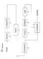
Fig. 8 is the block diagram of the base station of orthogonal code synchronization system and method.
Embodiment
Describe now the preferred embodiments of the present invention in detail, example shows in the accompanying drawings, and wherein identical reference number represents identical element in several diagrams.
Spread spectrum communication of the present invention and orthogonal code synchronization system and method are to have 07/626,109 sequence number and applying date December 14 nineteen ninety, present disclosed U.S. Patent number 5,228,056, the exercise question of being applied for by DonaldL.Schilling is the continuation of the disclosed invention of the U.S. Patent application of " synchronous spread spectrum communication system and method ".For intactly open, following discussion comprises the open part that appears in the original patent application, and enters subsequently the synchronized discussion of orthogonal code according to the present invention.
It is " transparent " that spread spectrum signal of the present invention is designed to for other user, that is to say, spread spectrum signal is designed to only have insignificant interference for other existing user's communication.The existence of spread spectrum signal is difficult to determine.This specific character is called as low possibility (LPI) and the low possibility (LPD) that detects intercepted and captured.The LPI of spread-spectrum and LPD characteristic allow the transmission between the user of a spread-spectrum cdma communication system, and the existing user of mobile cellular system can not experience significant interference.The present invention has utilized LPI and LPD about predetermined channel in mobile cellular system or in the fixed service microwave system.Power level by making each spread spectrum signal is lower than predetermined level, can not disturb mobile subscriber in mobile cellular system or the microwave user in the fixed service microwave system from the gross power of all spread-spectrums of the use in a honeycomb so.
Spread-spectrum is also anti-" obstruction " or interference.The frequency spectrum of frequency spectrum receiver expansion interference signal.This has reduced to come the interference of self-interference signal, thereby makes it can not reduce significantly the performance of spread spectrum system.It is useful for business correspondence that the characteristic of this interference reduction makes spread-spectrum, that is, can be superimposed upon spread spectrum waveform on existing narrow band signal.
The present invention has used the Direct swquence spread spectrum that utilizes phasing technique.Direct swquence spread spectrum is obtained the power that will launch, and it is expanded on very wide bandwidth, thereby makes power (watt/hertz) minimum of per unit bandwidth.When having completed this processing, the emission spread-spectrum power with relatively narrow bandwidth that is moved phone user or microwave user reception is only the sub-fraction of actual emission power.
In the fixed service microwave system, for example, if a spread spectrum signal with 10 milliwatts is expanded on the fixed service Microwave bandwidth of 10MHz, and the microwave user uses the communication system that only has as 2MHz channel width, in narrow-band communication system, the effective interference power that is caused by a spread spectrum signal is reduced to original 10MHz/2MHz/one so.User in the time of for 50 spread-spectrums, 50 times of the increase of output powers of the interference signal that is caused by spread-spectrum.
Causing the characteristic of the spread-spectrum of interference reduction to be that frequency spectrum receiver is actually the energy spread of any interference that receives on same wide bandwidth, is 10MHz in this example, and the initial bandwidth of the bandwidth reduction of the reception signal of wishing to it.For example, if the initial bandwidth of the message data of wishing is only 30kHz, the power of the interference signal that produces in the base station so is reduced to original 10MHz/30kHz/one.
The expansion of Direct swquence spread spectrum by utilizing one to complete frequency spectrum with respect to the strong broadband signal modulation primary signal of data bandwidth.Select this broadband signal to make it have two possible amplitudes ,+1 and-1, and these two amplitudes are periodically switched in a kind of " pseudorandom " mode.Therefore, in each equally spaced time interval, make Broad-band Modulated Signal and should be+1 or-1 judgement.If make this judgement with the mode of throwing coin, the sequence that obtains so can be true random.But under these circumstances, receiver can not a priori be known this sequence, and can not suitably receive and transmit.As an alternative, chip code (chip-code) generator produces an approximate random sequence electronically, is called pseudo random sequence, and it is all that priori is known for transmitter and receiver.
Code division multiple access
Code division multiple access (CDMA) is a kind of Direct swquence spread spectrum system, and wherein a plurality of, at least two, spread spectrum signal is communicated by letter simultaneously, and each operates on identical frequency band.In cdma system, give special chip code of each user.This chip code identifies this user.For example, if first user has first a chip code g
1(t), the second user has second a chip code g
2(t), etc., hope receiver of listening to first user receives whole energy that all users send on its antenna so.But, after going to expand the signal of first user, whole energy of this receiver output first user, and only export second, third, etc., the sub-fraction of the energy that the user sends.
CDMA is disturbed restriction.That is, can use same frequency spectrum and the user's of acceptable performance quantity is still arranged is to determine by make total interference power that all as a whole users produce in receiver.Unless note in the extreme power control, otherwise those CDMA transmitters near receivers will cause inundatory interference.This effect is called as " near-far away " (near-far) problem.In a mobile environment, near-problem far away may be main effect.Can control the power of each independent mobile remote subscriber, make that to move from each the power that remote subscriber receives identical.This technology is called " adaptive power control ".See that on March 3rd, 1992 is disclosed, by DonaldL.Schilling application, exercise question be the 5th, 093, No. 840 United States Patent (USP)s of " being used for the adaptive power control of spread spectrum system and method ", this patent is hereby expressly incorporated by reference.
Spread spectrum communication system of the present invention is a kind of code division multiple access (CDMA) system.Spread-spectrum CDMA can improve the utilization of frequency spectrum significantly.Utilize CDMA, each user in a honeycomb uses identical frequency band.But each CDMA signal has an independent pseudo noise code that makes receiver can distinguish the signal of hope from remaining signal.Remote subscriber in adjacent cell uses identical frequency band and identical bandwidth, thereby mutual " interference ".When the subscriber signal quantity of PCN base station reception increased, the signal of reception may show larger noise.
Each unwanted subscriber signal produces certain interference power, and the amplitude of this interference power depends on processing gain.Suppose that remote subscriber is evenly distributed in all adjacent cells, compare with the remote subscriber in a cellular-specific, the remote subscriber in adjacent cell makes the interfering energy of expection improve about 50%.Because disturb the increase factor not serious, so proportion is not multiplexing.
Each spread-spectrum honeycomb can be launched with whole 10MHz frequency bands, and all the 10MHz frequency band receives.Therefore, the coded data rate of the chip-rate of use per second 5,000,000 chips and 4800bps causes the processing gain of about every bit 1000 chips.Those of ordinary skill in the art know, can use simultaneously the maximum quantity of the CDMA remote subscriber of a frequency band to equal approx processing gain.
Orthogonal code
Think that now the pilot tone on return link is feasible because as the 5th, 506, No. 864 United States Patent (USP)s and the 5th, 544, disclose in No. 156 United States Patent (USP)s, it has reduced to obtain the required C/I of Eb/No of hope.This improvement comes from the synchronous or relevant ability that detects of using.Described in these patents, the use of pilot tone or general chip code has improved the performance of quadrature and nonopiate coding link.For orthogonal channel, because each mobile terminal needs unique pilot tone and information code, active user's quantity reduces two.If there is the code of limited quantity, this may have and seriously influences.The 5th, 506, No. 864 United States Patent (USP) uses are measured the base station of use non-orthogonal codes and the distance between mobile terminal from the pilot tone of mobile terminal.The present invention extends to this patent and comprises orthogonal code, and utilizes the phase place of regulating information channel to the information of the distance of mobile terminal, and it is aimed at other movable signal of arrival base station.Mobile terminal receives pilot tone or the general code chip-code-signal from the base station, and it sends to the far-end pilot signal of base station to utilize the timing of base station pilot signals and phase place to start.That is to say, the pilot tone of returning is not lingeringly passed through mobile terminal; The pilot tone of returning just looks like to be radar reflection from mobile terminal.Due to the many far-end pilot tones that will return to the base station being arranged, it is stronger on signal strength signal intensity certainly, and it is a but similarly pseudo noise code different from the base station pilot pseudo noise code.
The base station receive from the pilot signal of all current mobile terminal and in the time may being reduced to 0.1 chip measurement return to pseudo noise sequence and to the phase difference between the pseudo noise sequence of the emission of each far-end mobile radio station.Measured is round trip delay; Actual distance is half with the number of chip measurement, is accurate to 0.1 chip.This information is launched into the mobile subscriber, and if the mobile subscriber just operates with orthogonal modes on return link, the mobile subscriber utilizes this information to regulate the phase place of the PN code on far-end message, in order to arrive the base station in predetermined time as the base station is set up.Therefore, the PN code of far-end pilot tone and remote subscriber message channel is in different phase places, but they all have identical carrier signal, and pilot frequency carrier wave can be used for being created in relevant detection reference used in the user message channel.
Sampling of data point depends on the repetition rate of PN sequence usually, and will regulate on phase place, so that consistent with the data timing on the user message channel.Therefore, can reduce significantly the phase mutual interference that caused by the user message channel of communicating by letter with a sharing base station.
Interference from the mobile subscriber in adjacent cell is not quadrature, and shows as non-orthogonal interference.Most of orthogonal code CDMA system utilize fan anteena to obtain code reuse, and reduce and disturb.Therefore, at the edge of the honeycomb of crossing over sector surfaces, the mobile subscriber in each honeycomb is with maximum power transmission, and causes the radiation to two honeycombs with ceiling capacity.But during to their base station movement, they reduce their power as the mobile subscriber in adjacent cell, so that it keeps identical when the cell edge with them.Suppose 1/4th power decline curves, they with 1/4th power adjust the distance than their power of rate reduction, and because they are also leaving with it the base station of disturbing are occuring, the transmitted power level that they reduce (being reduced to 1/4th power) the one section distance that also reduces with 1/4th power factors of having advanced.This doubles the effect of 1/4th power factors, if this shows that the interference of not using power to control from the interference ratio of mobile subscriber's adjacent cell is much smaller.Therefore, the external disturbance of mixing at origination base station, namely from the mobile subscriber's of other base station operation interference ratio from other low 6db at least of interference that is causing in honeycomb with the mobile subscriber of origination base station operation.Therefore, can be increased to four times to user's quantity.As mentioned above, pilot channel of each current mobile user emission and information or message channel.Regulate information channel, making them is quadrature when arriving the base station.But pilot channel is not quadrature, but after information channel worked, pilot channel power had reduced 6db.Therefore, both made external disturbance and pilot channel, result of the present invention makes capabilities double.
Phase place by mobile far-end pilot tone after catching makes it overlap with the user profile channel can obtain another kind of the improvement.When completing this and process, the far-end pilot tone also becomes quadrature, and only interference is that user from adjacent cell is radiated the external disturbance in original honeycomb.As mentioned above, this interference reduces 6db at least, has caused capacity to increase four times.Due to mistake be produce in the base station and by the voltage-controlled oscillator of this mistake in mobile radio station, it is more difficult that the code tracking on reverse link becomes.Therefore, must use forward link that this mistake voltage is transmitted into mobile radio station.In general the distance change is relatively slow, and the control of the far-end of this mobile code clock is not a problem.When being enough to cause the unexpected fluctuation of fast serious mis-alignment, mobile radio station is moved back into acquisition mode to far-end pilot code code.In case recapture and completed necessity that information channel is brought back to suitable aligning and regulated after, mobile radio station switches gets back to the quadrature tracing mode.Therefore, only on the sub-fraction of time, the impact that produces on capacity is very little for nonopiate far-end pilot tone.If enough orthogonal codes are arranged with actual this advantage of utilizing in code set, so capacity should be still close to four times of non-orthogonal codes system.
Synchronous spread spectrum communication
As shown in Figure 2, a kind of spread spectrum CDMA (CDMA) communication system of using on communication channel 110 is provided, and it comprises fexible unit, information apparatus, expanding unit, adder unit, emitter, general extension frequency spectrum processing device, extension of message frequency spectrum processing device, catch and tracking means checkout gear, and synchronizer.Fexible unit and information apparatus are embodied as the general chip code generator 101 of transmitter and transmitter message chip code generator 102.Expanding unit is shown " different " device 103, can be an exclusive-OR gate.Adder unit is a combiner 105, and emitter comprises the transmitter of a signal source 108 that is presented as to be coupled in modulator 107.Transmitter message chip code generator 102 is coupled in " different " device 103.The general chip code generator 101 of the transmitter that illustrates is coupled in transmitter message chip code generator 102 and message data source.The general chip code generator 101 of " different " device 103 and transmitter is coupled in combiner 105.Modulator 107 is coupling between combiner 105 and communication channel 110.
At receiver, general extension frequency spectrum processing device is embodied as the general chip code generator 121 of receiver, general frequency mixer 123, and generalized ribbon bandpass filter 125.General frequency mixer 123 is coupling between the general chip code generator 121 of receiver and generalized ribbon bandpass filter 125.Extension of message frequency spectrum processing device is embodied as 122, one message frequency mixers 124 of a receiver message chip code generator, and a message band pass filter 126.Message frequency mixer 124 is coupling between receiver message chip code generator 122 and message band pass filter 126.Power divider 115 is coupling between communication channel 110 and general frequency mixer 123 and message frequency mixer 124.
Catch and be embodied as one with tracking means and catch and tracking circuit 131.Catch an output that is coupled to generalized ribbon bandpass filter 125 with tracking circuit 131, and be coupled to the general chip code generator 121 of receiver.Receiver message chip code generator 122 preferably is coupled to the general chip code generator 121 of receiver.
Checkout gear is embodied as a wave detector 139.Wave detector 139 is coupled in message band pass filter 126 and generalized ribbon bandpass filter 125.Wave detector 139 can be an asynchronous wave detector, for example envelope detector, or square-law detector.As selection, wave detector 139 can be a synchronous detector, and it is used to the recovered carrier signal from generalized ribbon bandpass filter 125.
Synchronizer comprises a device, low pass filter 128, and electronic switch 130.The position device is embodied as a bit synchronizer 129.Low pass filter 128 and electronic switch 130 are coupled in bit synchronizer 129.As shown in Figure 2, bit synchronizer 129 preferably is coupled to the general chip code generator 121 of receiver.As selection, bit synchronizer 129 can be coupled to an output of wave detector 139.
The general chip code generator 101 of transmitter produces general code chip-code-signal g
0(t), transmitter message chip code generator 102 produces message code chip-code-signal g
1(t).In Fig. 2, by the general code chip-code-signal data d that gives information
1(t), and the synchronization timing of message code chip-code-signal, although also can use other source, for example, be used for synchronized common clock signal." different " device 103 is by producing spread spectrum signal with message code chip-code-signal spread-spectrum processing messages data.Spread-spectrum is processed can be by completing the exclusive-OR of message data and message code chip-code-signal.Combiner 105 is with the signal combination of general code chip-code-signal and spread-spectrum processing.The signal that the general code chip-code-signal of combination and spread-spectrum are processed can be a multi-level signal with instantaneous voltage level of the signal that general code chip-code-signal and spread-spectrum process.
At a receiver, general extension frequency spectrum processing device is from CDMA signal x
c(t) recovered carrier signal cos ω
0T, and extension of message frequency spectrum processing device removes to expand CDMA signal x
c(t), become modulated message signal d
1(t).More particularly, with reference to figure 2, power divider 115 separates the CDMA signal that receives from communication channel 110.The general chip code generator 121 of receiver produces a general code chip-code-signal g
0(t) reproducing signals.General frequency mixer 123 utilizes the reproducing signals of general code chip-code-signal to remove to expand CDMA signal x from power divider 115
c(t), become recovered carrier signal.Has general code chip-code-signal g
0(t) cos ω
0The spread spectrum channel of the CDMA signal of t does not generally comprise data, thereby removes to expand the CDMA signal and only produce carrier signal.Generalized ribbon bandpass filter 125 is at carrier frequency, or ground of equal value filters recovered carrier signal at intermediate frequency.Compare with the enough message band pass filters 126 of wide bandwidth that have for modulated message signal filtering, generalized ribbon bandpass filter 125 can have and is the very narrow bandwidth of recovered carrier signal filtering.The very narrow bandwidth of generalized ribbon bandpass filter 125 helps to extract recovered carrier signal from noise.
Catch and catch and follow the tracks of recovered carrier signal with tracking circuit 131 from the output of generalized ribbon bandpass filter 125.Synchronize with recovered carrier signal through catching to make from the reproducing signals of the general code chip-code-signal of the general chip code generator 121 of receiver with tracking circuit 131.
Receiver message chip code generator 122 produces a message code chip-code-signal g
1(t) reproducing signals.With message code chip-code-signal g
1(t) reproducing signals with from the general code chip-code-signal g of the general chip code generator 121 of receiver
0(t) reproducing signals is synchronous.Therefore, through synchronization in the receiver message chip code generator 122 of the general chip code generator 121 of receiver have with through synchronization in identical synchronous of the transmitter message chip code generator 102 of the general chip code generator 101 of transmitter.Therefore, the spread spectrum communication channel that has a general code chip-code-signal provides the relevant spread-spectrum demodulation with the spread spectrum channel of data.
Wave detector 139 is demodulated into detected signal to modulated message signal.Detected signal by low pass filter 128 filtering, is sampled with electronic switch 130, and as receive data d
1(t) output.The receive data that is free from mistakes is identical with message data.Under the control of bit synchronizer 129, low pass filter 128 and electronic switch are brought into play respectively the function of " integration and dump ".
In a preferred embodiment, bit synchronizer 129 receptions are from the general code chip-code-signal g of the general chip code generator 121 of receiver
0(t) reproducing signals.The reproducing signals of general code chip-code-signal for example, can comprise the chip codeword with 8250 chips.Suppose that every chip codeword has 11, so every data bit has 750 chips.Because the reproducing signals of general code chip-code-signal provides the information of relevant chip codeword from where beginning to bit synchronizer 129, so bit synchronizer 129 is known the timing for synchronized corresponding position.
The present invention can also comprise the signal of processing for the treatment of a plurality of spread-spectrums of a plurality of information datas as the emission of CDMA signal.In this case, the present invention includes a plurality of information apparatus and a plurality of expanding unit.With reference to figure 3A, a plurality of information apparatus can be embodied as a plurality of transmitter message chip code generators, and a plurality of expanding units can be embodied as a plurality of exclusive-OR gates.A plurality of transmitter message chip code generators produce a plurality of message code chip-code-signals.In Fig. 3 A, a plurality of transmitter message chip code generators are shown as: produce the first message code chip-code-signal g
1(t) the first transmitter message chip code generator 102 produces the second message code chip-code-signal g
2(t) the second transmitter message chip code generator 172 is to producing N message code chip-code-signal g
N(t) N transmitter message chip code reflector 182.A plurality of exclusive-OR gates are shown as: the first exclusive-OR gate 103, the second exclusive-OR gates 173, and to N exclusive-OR gate 183.A plurality of exclusive-OR gates pass through a plurality of message data d
1(t), d
2(t) ..., d
N(t) respectively with a plurality of message code chip-code-signal g
1(t), g
2(t) ..., g
N(t) exclusive-OR produces the signal that a plurality of spread-spectrums are processed.More particularly, the first message data d
1(t) with the first message code chip-code-signal g
1(t) exclusive-OR, the second message data d
2(t) with the second message code chip-code-signal g
2(t) exclusive-OR is to N message data d
N(t) with N message code chip-code-signal g
N(t) exclusive-OR.
The general chip code generator 101 of transmitter is coupled in a plurality of transmitter message chip code generators and is used for a plurality of message data d
1(t), d
2(t) ..., d
N(t) source.In a preferred embodiment, general code chip-code-signal g
0(t) be a plurality of message code chip-code-signal g
1(t), g
2(t) ..., g
NAnd a plurality of message data d (t),
1(t), d
2(t) ..., d
N(t) provide synchronization timing.
Therefore, the CDMA signal comprises the signal that general code chip-code-signal and a plurality of spread-spectrum are processed, seemingly they each separately and synchronously have same carrier f
0The separate carrier signal on modulate, and launch by communication channel.
The present invention includes to receive and have the CDMA signal that a plurality of spread-spectrums are processed.Receiver also comprises a plurality of extension of message frequency spectrum processing devices, a plurality of detector arrangements, and a plurality of synchronizer.As shown in Fig. 3 B, a plurality of extension of message frequency spectrum processing devices can be embodied as a plurality of message chip code generators, a plurality of message frequency mixers, and a plurality of message band pass filter.A frequency mixer is connected between the message chip code generator and message band pass filter of a correspondence.A plurality of message frequency mixers are coupled in power divider 115.More particularly, a plurality of message chip code generators specifically are shown as the first message chip code generator 122, the second message chip code generators 172, to N message chip code generator 182.A plurality of message frequency mixers specifically are shown as the first message frequency mixer 124, the second message frequency mixers 174, to N message frequency mixer 184.A plurality of message bandpass filtering implement bodies are shown as the first message band pass filter 126, the second message band pass filters 176, to N message band pass filter 186.
A plurality of detector arrangements can be embodied as a plurality of first synchronous detector 127, the second synchronous detectors 177 that are shown, to the synchronous detector of N synchronous detector 187.Each in a plurality of synchronous detectors is coupled in a plurality of message band pass filters.
A plurality of synchronizers can comprise a bit synchronizer 129, a plurality of low pass filters, and a plurality of electronic switch.A plurality of low pass filters are shown as: the first low pass filter 128, the second low pass filters 178, and to N low pass filter 188.A plurality of electronic switches are shown as: the first electronic switch 130, the second electronic switches 180, and to N electronic switch 190.Each in a plurality of synchronous detectors is coupled in an output of generalized ribbon bandpass filter 125.Recovered carrier signal from generalized ribbon bandpass filter 125 is used as reference signal, and being used for is each synchronous demodulation of a plurality of message data signals a plurality of receive data d by a plurality of synchronous detectors
1(t), d
2(t) ..., d
N(t).
As selection, detector arrangement can be embodied as a plurality of asynchronous wave detectors, and for example, envelope detector 139,189,199 is as shown in Fig. 3 C.Asynchronous wave detector does not generally need recovered carrier signal.
Utilize the present invention who embodies in Fig. 3 B, as mentioned above, provide recovered carrier signal as the general extension spectral channel of a CDMA signal part.Catch with tracking circuit 131 and catch and follow the tracks of recovered carrier signal from an output of generalized ribbon bandpass filter 125.Reproducing signals from the general code chip-code-signal of the general chip code generator 121 of receiver is synchronized with through catching the recovered carrier signal with tracking circuit 131.The general chip code generator 121 of receiver produces general code chip-code-signal g
0(t) reproducing signals, it provides to bit synchronizer 129 with to the timing of a plurality of receiver message chip code generators 122,172,182.
The present invention also comprises a kind of method for synchronous demodulation CDMA signal.Message data is input to expanding unit.With reference to figure 4, the method comprises the step that produces 403 general code chip-code-signals.The method comprises that also producing 405 is synchronized with the message data of general code chip-code-signal, and produces the 407 message code chip-code-signals that are synchronized with the general code chip-code-signal.Use a spread spectrum modulator with message code chip-code-signal processing messages data, produce the signal that spread-spectrum is processed.Signal combination 409 with general code chip-code-signal and spread-spectrum processing.The method is launched by communication channel the signal of the general code chip-code-signal of combination and spread-spectrum processing on carrier signal as the CDMA signal.
At receiver, the method comprises from the CDMA signal recovers 413 carrier signals, and the CDMA signal is gone to expand 415 is modulated message signal.Recovered carrier signal is used for synchronously going to expand the step of CDMA signal, and selectively is used for synchronous demodulation 417 and output 419 modulated message signal as the data that receive.
In the use of the system shown in Fig. 3 A, the general chip code generator 101 of transmitter produces general code chip-code-signal g
0(t).Message code chip-code-signal g with spontaneous emission machine message chip code generator 102 since " different " device 103
1(t) spread-spectrum processing messages data.Combiner 105 is with the signal combination of general code chip-code-signal and spread-spectrum processing.The signal of combination can be, for example, multi-level signal, it be the signal processed by general code chip-code-signal and spread-spectrum voltage level linearly addition produce, or the voltage level addition generation of the signal that general code chip-code-signal and a plurality of spread-spectrum are processed.Transmitter has carrier frequency f
0Carrier signal on the general code chip-code-signal of emission combination and the signal that a plurality of spread-spectrum is processed.The CDMA signal is by communication channel 110 emissions.
As shown in Fig. 3 B, at receiver, general extension frequency spectrum processing device is embodied as co-operation with from the general chip code generator 121 of the receiver of CDMA signal recovered carrier signal, general frequency mixer 123, and generalized ribbon bandpass filter 125.Extension of message frequency spectrum processing device is embodied as the collaborative receiver message chip code generator 122 that the CDMA signal is gone to expand to modulated message signal, message frequency mixer 124, and message band pass filter 126.The reproducing signals that preferably receiver message chip code generator 122 is synchronized with from the general code chip-code-signal of the general chip code generator 121 of receiver.Can use a plurality of receiver message chip code generators that are synchronized with the reproducing signals of general code chip-code-signal.Be embodied as and be synchronized with the synchronizer of the synchronous detector 127 of recovered carrier signal, modulated message signal is demodulated into the data of reception.
Under the control of bit synchronizer 129, the data that low pass filter 128 and electronic switch 130 integrations and dump receive.Bit synchronizer 129 preferably comes synchronization integration and dump function with the reproducing signals of general code chip-code-signal.
The spread-spectrum geo-location
The invention provides a kind of spread spectrum CDMA that uses on communication channel (CDMA) communication and geo-positioning system and method, it comprises at least one base station and a plurality of far-end unit.Far-end unit can be mobile or on fixing resting position.Message data is transmitted between base station and far-end unit.Message data comprises, but is not limited to, digitized speech, and computer data, facsimile data, video data, etc.Base station message data is transmitted to a plurality of far-end units in the base station.Far-end unit transmits far-end message data to the base station.Here base station message data is defined as the message data that starts from the base station, and far-end message data is defined as the message data that starts from far-end unit here.Discussed below is a preferred embodiment, and the distance between base station and far-end unit is determined in the base station.The role of base station and far-end unit can exchange, and this moment, distance was determined at far-end unit, and this is of equal value to those skilled in the art.
In the example arrangement shown in Fig. 5, the base station comprises the base station expanding unit, base station fexible unit, base station combiner apparatus, base station transmitter, and antenna for base station." base station " vocabulary as prefix shows the element that is positioned at the base station, or the signal that starts from the base station.
Base station expanding unit spread-spectrum is processed base station message data d
1(t).The base station expanding unit is embodied as a base station spread spectrum modulator.The base station spread spectrum modulator is illustrated as a message chip code generator 502 and an exclusive-OR gate 503.Exclusive-OR gate 503 is coupled in message chip code generator 502.Message chip code generator 502 uses a chip codeword to produce for spread-spectrum and processes base station message data d
1(t) chip code sequence.Modulo addition spread-spectrum by exclusive-OR gate 503 is processed the chip code sequence from message chip code generator 502.Those of ordinary skill in the art know, there is the circuit of many equivalences can be used for the base station spread spectrum modulator, these circuit comprise, but be not limited to, be used for the chip code sequence be multiply by the product device of base station message data, matched filter and the surface acoustic wave device with the impulse response that is matched with the chip code sequence.
The base station fexible unit produces base station general code chip-code-signal.As " general " vocabulary of prefix show the general code chip-code-signal be one unmodulated, or low data rate, the Direct swquence spread spectrum signal, it can be used as pilot channel.Pilot channel can obtain regularly the user, and is provided for the phase reference of coherent demodulation.The base station fexible unit is embodied as a general chip code generator 501 in base station.The general chip code generator 501 in base station utilizes the chip codeword of sharing with all far-end units of base station communication to produce base station general code chip-code-signal.Message chip code generator 501 is coupled in the general chip code generator 502 in base station, is used for deriving sharing regularly.As selection, can provide timing signal for the general chip code generator 501 of message chip code generator 502 and base station with a common clock.
The base station combiner apparatus is with the base station message data combination of base station general code chip-code-signal and spread-spectrum processing, to produce base station CDMA signal.The base station combiner apparatus is embodied as a base station combiner 505.Base station combiner 505 is coupled in the general chip code generator 501 in base station and exclusive-OR gate 503.Base station combiner 505 is base station general code chip-code-signal and the base station message data addition linearly of processing from the spread-spectrum of exclusive-OR gate 503.Signal at the output gained of base station combiner 505 is code division multiple access (CDMA) signal, is expressed as base station CDMA signal here.The base station CDMA signal of gained also can use various optional nonlinear combination, as long as can make its channel be detected at frequency spectrum receiver.
The base station transmitter device is from the base station to far-end unit transmitting base station CDMA signal.The base station transmitter device is embodied as signal source 508 and product device 507.Product device 507 is coupling between base station combiner 505 and signal source 508.Signal source 508 is at the first carrier frequency f
1Produce the first carrier signal.507 base station CDMA signal times of exporting from base station combiner 505 of product device are with the first carrier signal.Knownly in the prior art can be placed in the carrier frequency of selection to the signal of wishing with other ballistic device.
Antenna for base station 509 is coupled in the base station transmitter device by an isolator 513.Antenna for base station 509 is with the first carrier frequency radiation base station CDMA signal.
As shown in Figure 6, far-end unit comprises far-end antenna 511, far-end detector arrangement, far-end expanding unit, far-end combiner apparatus, and distant transmitter device.Each far-end unit also can comprise the far-end fexible unit.Show as " far-end " vocabulary of prefix the element that is positioned at far-end unit, or the signal that starts from far-end unit.
The base station CDMA signal that far-end antenna 511 receives from the base station radiation.
The far-end detector arrangement is coupled in far-end antenna 511.The far-end detector arrangement is the base station general code chip-code-signal detection that is embedded in the CDMA signal of base station.Use the base station general code chip-code-signal of detection, the far-end detector arrangement recovers from the base station message data of base station propagation.Far-end unit can be launched the base station general code chip-code-signal of detection again, or as selecting, can make the far-end fexible unit produce a different far-end general code chip-code-signal.
In Fig. 6, the far-end detector arrangement is embodied as product device 536, band pass filter 537 is caught and tracking circuit 538, general chip code generator 539, message chip code generator 541, product device 542, band pass filter 543, data wave detector 544, low pass filter 545, and bit synchronizer 540.As known in the art, can use the same function of other device and circuit performance, include, but not limited to matched filter, surface acoustic wave device, etc.The base station general code chip-code-signal that is embedded in the CDMA signal of base station is caught and followed the tracks of to this circuit.Receive base station CDMA signal at far-end antenna 511, and make it pass through isolator 534 and power divider 535.With product device 536, band pass filter 537, catch and tracking circuit 538, and general chip code generator 539 is base station general code chip-code-signal detection.Identical with described in previous section of the function of this circuit.Utilize message chip code generator 541, product device 542, band pass filter 543, data wave detector 544, low pass filter 545, and synchronizer 540 is used for the base station general code chip-code-signal of detection to recover to be embedded in the base station message data of base station CDMA signal.Data wave detector 544 can coherently or incoherently operate.Detection base station message data is as the d of detection data
R1(t) output.
If base station general code chip-code-signal is combined as the part of far-end CDMA signal, do not need so general chip code generator 546, because the base station general code chip-code-signal of available general chip code generator 539 outputs.If use the far-end general code chip-code-signal different from base station general code chip-code-signal, can produce far-end general code chip-code-signal with general chip code generator 546 so.Under latter event, far-end general code chip-code-signal regularly or be synchronized with detection base station general code chip-code-signal.For the purpose of discussing, far-end general code chip-code-signal is thought of as from far-end unit sends to the base station, should know that also far-end general code chip-code-signal can be with detection base station general code chip-code-signal be identical, or same.
Far-end expanding unit spread-spectrum is processed far-end message data.The far-end expanding unit is embodied as a far-end spread spectrum modulator.The far-end spread spectrum modulator is shown as a message chip code generator 548 and an exclusive-OR gate 547.Exclusive-OR gate 547 is coupled in message chip code generator 548.Message chip code generator 548 utilizes a chip codeword to produce for spread-spectrum and processes far-end message data d
2(t) chip code sequence.Exclusive-OR gate 547 use modulo additions are processed carry out spread-spectrum from the chip code sequence of message chip code generator 548.Those of ordinary skill in the art know, the circuit of many equivalences can be used as the far-end expanding unit, includes, but not limited to for the chip code sequence being multiply by product device, matched filter and the surface acoustic wave device of base station message data.
The far-end combiner apparatus is combined as far-end CDMA signal to the far-end message data of far-end general code chip-code-signal and spread-spectrum processing.The far-end combiner apparatus is embodied as a far-end combiner 549.Far-end combiner 549 is coupled in exclusive-OR gate 547, and the general chip code generator 546 of far-end, or as selecting to be coupled in general chip code generator 539.Far-end combiner 549 is far-end general code chip-code-signal and the far-end message data addition linearly of processing from the spread-spectrum of exclusive-OR gate 547.The signal that produces at far-end combiner 549 outputs is code division multiple access (CDMA) signal, is expressed as far-end CDMA signal here.Also can various other nonlinear combination of choice for use, as long as the far-end CDMA signal that produces can make its channel be detected at frequency spectrum receiver.
Far-end unit also comprises the distant transmitter device for the emission far-end CDMA signal from far-end unit to the base station.The distant transmitter device is embodied as signal source 551 and product device 550.Product device 550 is coupling between far-end combiner 549 and signal source 551.Signal source 551 is at the second carrier frequency f
2Produce carrier signal.Product device 550 will be from the far-end CDMA signal times of far-end combiner 549 output with the second carrier signal.Knownly in this area can be placed in selected carrier frequency to the signal of wishing with other ballistic device.The second carrier frequency can be identical or different with the first carrier frequency.
Far-end antenna 511 is coupled in the distant transmitter device by an isolator 534.Far-end antenna 511 is with the second carrier frequency radiation far-end CDMA signal.
Each base station also comprises base station detector arrangement and distance means.The base station detector arrangement is coupled in antenna for base station 509 by isolator 513 and power divider 515.The base station detector arrangement detects the far-end general code chip-code-signal that is embedded in far-end CDMA signal.As shown in Figure 5, the base station detector arrangement can be embodied as a base station wave detector, and it can comprise product device 523, band pass filter 525, catch and tracking circuit 531, general chip code generator 521, message chip code generator 522, product device 524, band pass filter 526, data wave detector 527, low pass filter 528, and bit synchronizer 529.As known in the art, can realize the base station detector arrangement with other device and the circuit of carrying out identical function, other device and circuit include, but not limited to matched filter, surface acoustic wave device, etc.The far-end general code chip-code-signal that is embedded in far-end CDMA signal is caught and followed the tracks of to this circuit.Receive far-end CDMA signal at antenna for base station 509, and by isolator 513 and power divider 515.Utilize product device 523, band pass filter 525 is caught with tracking circuit 531 and general chip code generator 521 and is detected far-end general code chip-code-signal.The function of this circuit as previously described.With message chip code generator 522, product device 524, band pass filter 526, data wave detector 527, low pass filter 528, bit synchronizer 529 is used for detection far-end general code chip-code-signal to recover to be embedded in the far-end message data of far-end CDMA signal.Data wave detector 527 can coherently or incoherently operate.Detection far-end message data is as the d of detection data
R2(t) output.Therefore, the base station wave detector utilizes detection far-end general code chip-code-signal to recover the far-end message data that transmits from far-end unit.
Utilize detection far-end general code chip-code-signal and base station general code chip-code-signal, distance means is determined the range delay between far-end unit and base station.Distance means is embodied as a range delay device 530, and it can be relatively from the base station general code chip-code-signal of general chip code generator 501 and from the timing between the far-end of the detection general code chip-code-signal of general chip code generator 521.
The present invention may further include step: spread-spectrum is processed base station message data; Produce base station general code chip-code-signal; The base station message data that combined base station general code chip-code-signal and spread-spectrum are processed, thereby produce base station CDMA signal; From the base station to far-end unit transmitting base station CDMA signal; Detection is embedded in the base station general code chip-code-signal in the CDMA signal of base station; Utilizing, general code chip-code-signal in detection base station recovers base station message data; Spread-spectrum is processed far-end message data; Utilize the remote data that the chip-code-signal of detection general code and spread-spectrum are processed to produce far-end CDMA signal; The emission far-end CDMA signal from far-end unit to the base station; Detection is embedded in the far-end general code chip-code-signal in far-end CDMA signal; Utilizing, detection far-end general code chip-code-signal recovers far-end message data; And utilize detection far-end general code chip-code-signal and base station general code chip-code-signal to determine range delay between far-end unit and base station.
In use, base station message data is processed with a message code chip-code-signal spread-spectrum in the base station, and base station message data and the base station general code chip-code-signal that spread-spectrum is processed made up.The signal of combination is a base station CDMA signal that is transmitted at least one far-end unit by communication channel.
Far-end unit receives base station CDMA signal, and detection is embedded in the base station general code chip-code-signal in the CDMA signal of base station, and uses detection base station general code chip-code-signal to recover to be embedded in base station message data in the CDMA signal of base station.
General code chip-code-signal in detection base station postpones to be far-end general code chip-code-signal, or arranges regularly for the different far-end general code chip-code-signals that send to the base station from far-end unit with it.Far-end unit far-end chip code signal extension frequency spectrum processing far-end message data, and far-end message data and far-end general code chip-code-signal that spread-spectrum is processed are combined as a far-end CDMA signal.Far-end CDMA signal is sent to the base station by communication channel.
In the base station, from far-end CDMA signal demodulator far-end general code chip-code-signal, and detection far-end general code chip-code-signal has been used for the far-end message data that detection is embedded in far-end CDMA signal.In addition, detection far-end general code chip-code-signal and base station general code chip-code-signal comparison in the range delay circuit, leave the distance of base station to determine far-end unit.In fact, the distance between far-end unit and base station is to send the chip codeword sequence that has produced base station general code chip-code-signal and the function that receives timing between the sequence that is produced by the chip codeword that has produced far-end general code chip-code-signal.
Utilize radio frequency (RF) signal to determine that the concept of distance is well known in the art.The RF signal should have fixing propagation rate, 3 * 10
8Meter per second.The RF signal left transmitter sometime before it arrives receiver.The particular sequence of base station general code chip-code-signal and far-end general code chip-code-signal is used as time mark.Base station general code chip-code-signal sequence that the receiver of far-end unit is seen with in the time difference of this sequence of base station transmitter place, directly and the distance dependent between base station and far-end unit.Equally, the far-end general code chip-code-signal sequence of seeing at the receiver of base station with in the time difference of this sequence of the transmitter place of far-end unit, directly and the distance dependent between far-end unit and base station.
In the use of base station general code chip-code-signal and far-end general code chip-code-signal and radar system, echo-ranging used is identical type.Many radar systems are sent the pulse of RF energy simply, then wait for the part energy of returning from the target reflection due to pulse.Radar signature is from impulse ejection constantly until its time of returning.It is function to the round distance of target that the required time is returned in pulse.Be easy to determine distance from the propagation velocity of signal.
Spread spectrum signal of the present invention has same distance/time relationship.The advantage of spread spectrum signal of the present invention is: its phase place is easy to differentiate.The base resolution of base station code chip-code-signal or far-end chip code burst is a code chip.Therefore, chip-rate is higher, and measurability is better.Thereby in the chip-rate of 10M chips/sec, fundamental distance resolution is 10
-7Second, or 30 meters.The additional delay that also will consider to run in the far-end unit circuit.Determine between base station and far-end unit apart from the time, can be in these delays of base-stations compensate.
Orthogonal code is synchronous
Also the present invention can be presented as a kind of utilize orthogonal code and to the information of the distance of mobile terminal regulate and the phase place of alignment information channel in order to obtain the system and method for orthogonality at antenna for base station.
Utilize orthogonal code and comprise in the system that antenna for base station obtains orthogonality to the information of the distance of mobile terminal: a plurality of mobile terminals and a base station.Each in a plurality of mobile terminals comprises far-end spread-spectrum processing unit, far-end pilot tone device, composite set, far-end emitter, and code phases adjusting device.
Far-end spread-spectrum processing unit and far-end pilot tone device are coupled in composite set.The far-end emitter is coupled in composite set.
The base station comprises receiving system, the first base station pilot device, the second base station pilot device, the first deferred mount, the second deferred mount, correlator, tracking means, range delay device, and base station emitter.
Far-end spread-spectrum processing unit utilizes pseudo noise code to process far-end message data.Far-end pilot tone device produces the far-end pilot signal.Composite set produces the far-end composite signal to the far-end message data combination of far-end pilot signal and spread-spectrum processing.The far-end composite signal has far-end pilot signal and at least one remote subscriber information channel.The far-end emitter is launched the far-end composite signal to the base station on the backward channel of duplex wireless channel.
In the base station, receiving system receives the far-end composite signal.The first base station pilot device produces base station pilot signals.The second base station pilot device produces the base station pilot reference signal.One of the first deferred mount generation base station pilot reference signal is punctual, and one leading, and a delay signal.The second deferred mount produces the information reference signal.The information reference signal is synchronizeed with the punctual signal of base station pilot reference signal.Correlator is punctual, the lead and lag signal multiplication of far-end composite signal and base station pilot reference signal, so that punctual, leading and delay signal of the far-end pilot signal of being correlated with out respectively.Correlator is also far-end composite signal and information reference signal multiplication, with the remote subscriber information channel of being correlated with out.
Tracking means is followed the tracks of the phase place of far-end pilot signal, and the peak value of response far-end pilot signal, the output lock-on signal.Lock-on signal represents synchronizeing of far-end pilot signal and base station pilot reference signal.
The response lock-on signal, the phase difference between range delay device calculation base station pilot signal and base station pilot reference signal is to determine the distance between mobile radio station and base station.The base station emitter is launched this distance by the forward channel of duplex wireless channel from the base station to mobile terminal.
The range information that response receives from the base station, the phase place of regulating pseudo noise code in the code phases adjusting device of mobile terminal is in order to determine that the far-end message data of spread-spectrum processing arrives the time of base station.
When regulating the phase place of pseudo noise code, far-end spread-spectrum processing unit can be with the incremental adjustments pseudo noise code of a code chip.When mobile terminal was regulated pseudo noise code, base station processor is the level of signal strength of the far-end message data of spread-spectrum processing relatively.The code chip increment that response is strengthened operating characteristic most, base station calibration far-end pilot signal and have relation between the far-end message data that the spread-spectrum of this code chip increment processes.
Spread-spectrum cdma cellular wireless communication system may further include base station expanding unit and group of base stations locking device.Base station expanding unit spread-spectrum is processed base station message data.The base station expanding unit can comprise for the treatment of a device with the base station message data of the specific mobile terminal of selected chip code.Base station message data and base station pilot signals that the group of base stations locking device is processed spread-spectrum are combined as a compound base station signal.Compound base station signal comprises a shared spread-spectrum pilot signals and at least one proprietary extensions spectrum users information channel for each mobile terminal.The extended code of each in shared spread-spectrum pilot signals and proprietary extensions spectrum users information channel can comprise an orthogonal symbol.The far-end pilot signal can be subordinated to and share spread-spectrum pilot signals as the phase place that is used for the far-end pilot signal and reference regularly.
The extended code of the remote subscriber information channel of far-end pilot signal and each mobile terminal can comprise an orthogonal symbol.In addition, can be synchronized with the far-end pilot signal to the remote subscriber information channel.
System can also comprise for generation of error signal and follow the tracks of the base station delay lock loop device of far-end pilot signal.The error signal that the mobile terminal response receives from the base station, the phase place of regulating the orthogonal PN code is so that compensation change on distance when mobile terminal moves in honeycomb.
More particularly, mobile terminal of the present invention comprises the remote subscriber data source, the first orthogonal code set generator, first kind noise code generator, far-end source of pilot data, signal combiner, the first modulo 2 adder, the second modulo 2 adder, the 3rd modulo 2 adder, the 4th modulo 2 adder, modulator, antenna assembly, code phases adjuster, and processor.
The first modulo 2 adder is coupled in remote subscriber data source and the first orthogonal code set generator.The second modulo 2 adder is coupled in output and the first kind noise code generator of the first modulo 2 adder.The 3rd modulo 2 adder is coupled in the first orthogonal code set generator and far-end source of pilot data.The 4th modulo 2 adder is coupled in output and the first kind noise code generator of the 3rd modulo 2 adder.Signal combiner is coupled in the 4th modulo 2 adder and the second modulo 2 adder.Modulator is coupled in signal combiner.The code phases adjuster is coupled in the first orthogonal code set generator and first kind noise code generator.Processor is coupled in the code phases adjuster.
The remote subscriber data source produces user data signal.The first orthogonal code set generator produces the first orthogonal code and the first far-end pilot code.The first modulo 2 adder is with the first orthogonal code spread-spectrum processes user data signal, in order to produce spread signal.First kind noise code generator produces the first pseudo noise code.The second modulo 2 adder is processed this spread signal with the first pseudo noise code, to produce the spread-spectrum user data signal.
The far-end source of pilot data produces the pilot data signal.The pilot data signal can all form by 1.As selection, the far-end source of pilot data can produce all by the 0 pilot data signal that forms.
The 3rd modulo 2 adder is processed the pilot data signal with the first far-end pilot code spread-spectrum, produces the expansion pilot signal.The 4th modulo 2 adder is processed the expansion pilot signal with the first pseudo noise code, produces far-end spread-spectrum pilot data signal.
Signal combiner is combined into far-end spread-spectrum pilot data signal and spread-spectrum user data signal the spread-spectrum data-signal of combination.Modulator with the combination the spread-spectrum data signal modulation to carrier wave, become the spread-spectrum modulation data-signal of combination.Antenna assembly is launched the spread-spectrum modulation data-signal of combination on the backward channel of duplex wireless channel.Antenna assembly also receives the compound spread-spectrum modulation carrier signal of launching in the forward channel of duplex wireless channel from the base station.Compound spread-spectrum modulation carrier signal on forward channel has the proprietary extensions spectrum users information channel of shared spread-spectrum pilot signals and mobile terminal.
The code phases adjuster, response comes input and the shared spread-spectrum pilot signals of self processor, and the phase place of regulating the first orthogonal code arrives the time of base station to regulate the spread-spectrum user data signal.Making the spread-spectrum user data signal of itself and other arrival the time of advent that the spread-spectrum user data signal is regulated in the operation of this phase adjusted is quadrature.The base station make the phase place of the first far-end pilot code be subordinated to shared spread-spectrum pilot signals, so that can utilize the distance between the definite base station of round trip delay and mobile terminal.The distance between base station and mobile terminal is inputted and stored to processor generation processor.
The code phases adjuster can also be regulated the phase place of the first orthogonal code, makes it have the phase place identical with the first pseudo noise code.The length of the first pseudo noise code is the integral multiple of the first orthogonal code length.The code phases adjuster can also respond the phase place of catching mobile the first far-end pilot code, and it is synchronizeed with the spread-spectrum user data signal.
Mobile terminal of the present invention may further include power divider, the second orthogonal code set generator, Equations of The Second Kind noise code generator, pattern is controlled and capture device, clock pulse generator, the 5th modulo 2 adder, the 6th modulo 2 adder, the first delay device, the second delay device, the first multiplier/correlator, the second multiplier/correlator, the 3rd multiplier/correlator, the 4th multiplier/correlator, delay lock loop, and phase locked loop oscillator.
Pattern is controlled and capture device is coupling between the second orthogonal code set generator and Equations of The Second Kind noise generator.Clock pulse generator is coupled in pattern control and capture device, the first orthogonal code set generator and first kind noise code generator.The 5th modulo 2 adder is coupled in the second orthogonal code set generator and Equations of The Second Kind noise code generator.The 6th modulo 2 adder is coupled in the second orthogonal code set generator and Equations of The Second Kind noise code generator.The first delay device is coupled in the 5th modulo 2 adder.Each is coupled in power divider and the first delay device first, second and the 3rd multiplier/correlator.The second delay device is coupled in the 6th modulo 2 adder and processor.The 4th multiplier/correlator is coupled in the second delay device and power divider.Delay lock loop is coupled in second and the 3rd multiplier/correlator.Phase locked loop oscillator is coupled in the first multiplier/correlator.
Power divider is separated into a pilot channel and a data channel to compound spread-spectrum modulation carrier signal.The second orthogonal code set generator, response produce a plurality of local pilot code that produce from the order of base station, can produce and/or use at any given time any one in them, or a plurality of arbitrarily in them.
The Equations of The Second Kind noise code generator produces the second pseudo noise code.Pattern control and capture device receive the timing information from the base station, and produce the clock that is used for the second orthogonal code set generator and Equations of The Second Kind noise code generator.Pattern is controlled and capture device also produces synchronizing signal.Clock pulse generator provides synchronizing clock signals.Clock pulse generator can have the oscillator of itself, maybe can be locked in the clock of self mode control and capture device.
Pilot code and second pseudo noise code of the 5th modulo 2 adder combination First ground generation are to form the first local spread-spectrum pilot reference signal.The 6th modulo 2 adder combination one specific orthogonal code and the second pseudo noise code is to form the first local spread-spectrum information reference signal.The first delay device, answer processor postpones the first local spread-spectrum pilot reference signal, to produce punctual, leading and delay signal of the first local spread-spectrum pilot reference signal.
First, second, and third multiplier/correlator shares punctual, the leading and delay signal of spread-spectrum pilot signals with punctual, the lead and lag signal multiplication of compound spread-spectrum modulation carrier signal and the first local spread-spectrum pilot reference signal to be correlated with out respectively.The second delay device provides the information reference signal of synchronizeing with the punctual signal of the first local spread-spectrum pilot reference signal.The 4th multiplier/correlator multiplies each other compound spread-spectrum modulation carrier signal and the first local spread-spectrum information reference signal, with the proprietary extensions spectrum users information channel of being correlated with out.Delay lock loop is followed the tracks of the phase place of the shared spread-spectrum pilot signals of input, and the response correlation peak is controlled and capture device clock signal and lock-on signal to pattern.Phase locked loop oscillator concentrates on correlation peak, and provides the coherent carrier reference to local data wave detector and delay lock loop.
Utilize the system of explanation just now, distance between base station and mobile terminal can be determined by measuring the code phase difference that shares between spread-spectrum pilot signals and the first far-end pilot code in the base station.Shared spread-spectrum pilot signals can comprise orthogonal symbol.The first far-end pilot code also can comprise orthogonal symbol.
In spread-spectrum CDMA digital cellular wireless system of the present invention, system also comprises a base station.The base station comprises the base station user data source, the first orthogonal code set generator, first kind noise code generator, the first modulo 2 adder, the second modulo 2 adder, DSN, the system data expanding unit, base station pilot data source, pilot data expanding unit, signal combiner, modulator, antenna assembly, the pilot reference signal generating means, clock pulse generator, range delay device, and processor.
The first modulo 2 adder is coupled in base station user data source and the first orthogonal code set generator.The second modulo 2 adder is coupled in output and the first kind noise code generator of the first modulo 2 adder.Signal combiner is coupled in pilot data signal extension device, system data expanding unit, and the second modulo 2 adder.Modulator is coupled in signal combiner.Clock pulse generator is coupled in the first orthogonal code set generator and first kind noise code generator.The range delay device is coupled in output of pilot data expanding unit and an output of pilot reference signal generating means.
The base station user data source produces the base station user data signal.The first orthogonal code set generator produces the first orthogonal code and the first base station pilot code.The first modulo 2 adder is processed the base station user data signal with the first orthogonal code spread-spectrum, to produce spread signal.First kind noise code generator produces the first pseudo noise code.The second modulo 2 adder is processed spread signal with the first pseudo noise code, to produce the spread-spectrum user data signal.DSN produces the system data that will be transmitted into a plurality of mobile terminals.System data expanding unit spread-spectrum treatment system data.The base station pilot data source produces the base station pilot data-signal.Pilot data signal extension device is treated to shared spread-spectrum pilot signals to base station pilot data-signal spread-spectrum with the first base station pilot code.
Signal combiner will share spread-spectrum pilot signals, the spread spectrum system data, and the spread-spectrum user data signal is combined as the spread-spectrum data-signal of combination.Modulator with the combination the spread-spectrum data signal modulation to a carrier wave, become the spread-spectrum modulation data-signal of combination.The spread-spectrum modulation data-signal of antenna assembly emission combination.Antenna assembly also receives a plurality of compound spread-spectrum modulation carrier signal of launching from a plurality of mobile terminals respectively.Each compound spread-spectrum modulation carrier signal has the far-end spread-spectrum pilot signals of reception and is used for the information channel of each mobile terminal.
The pilot reference signal generating means produces pilot reference signal.Clock pulse generator keeps the total system time.The phase difference that the range delay device calculates between pilot reference signal and shared spread-spectrum pilot signals is worth as first.Processor storage the first value, and utilize the first value that the output signal of processor that represents that round trip postpones is provided to mobile terminal.
Pilot data signal extension device can comprise the 3rd modulo 2 adder, and the 4th modulo 2 adder.The 3rd modulo 2 adder is coupled in the first orthogonal code set generator and base station pilot data source.The 4th modulo 2 adder is coupled in output and the first kind noise code generator of the 3rd modulo 2 adder.
The 3rd modulo 2 adder is processed the pilot data signal with the first base station pilot code spread-spectrum, to produce the expansion pilot signal.The 4th modulo 2 adder is processed the expansion pilot signal with the first pseudo noise code, to produce shared spread-spectrum pilot signals.
The system data expanding unit can comprise the 5th modulo 2 adder and the 6th modulo 2 adder.The 5th modulo 2 adder is coupled in the first orthogonal code set generator and DSN.The 6th modulo 2 adder is coupled in output and the first kind noise code generator of the 5th modulo 2 adder.
The first orthogonal code set generator produces the second orthogonal code.The 5th modulo 2 adder is with the second orthogonal code spread-spectrum treatment system data, to produce the spread-spectrum data-signal.The 6th modulo 2 adder is processed the spread-spectrum data-signal with the first pseudo noise code, to produce the spread spectrum system data-signal.
The base station may further include power divider, the second orthogonal code set generator, Equations of The Second Kind noise code generator, pattern is controlled and capture device, the 7th modulo 2 adder, the 8th modulo 2 adder, the first delay device, the second delay device, the first multiplier/correlator, the second multiplier/correlator, the 3rd multiplier/correlator, the 4th multiplier/correlator, delay lock loop, and phase locked loop oscillator.
Pattern is controlled and capture device is coupling between the second orthogonal code set generator and Equations of The Second Kind noise code generator.The 7th modulo 2 adder is coupled in the second orthogonal code set generator and Equations of The Second Kind noise code generator.The 8th modulo 2 adder is coupled in the second orthogonal code set generator and Equations of The Second Kind noise code generator.The first delay device is coupled in the 7th modulo 2 adder.The second delay device is coupled in the 8th modulo 2 adder and processor.Each is coupled in power divider and the first delay device first, second and the 3rd multiplier/correlator.The 4th multiplier/correlator is coupled in the second delay device and power divider.Delay lock loop is coupled in second and the 3rd multiplier/correlator.Phase locked loop oscillator is coupled in the first multiplier/correlator.
Power divider is separated into a pilot channel and a data channel with compound spread-spectrum modulation carrier signal.The second orthogonal code set generator produces the 3rd orthogonal code.The Equations of The Second Kind noise code generator produces the second pseudo noise code.Pattern is controlled and capture device provides clock and control signal.
Pilot tone orthogonal code and the second pseudo noise code that the 7th modulo 2 adder combination distributes are to form the first spread-spectrum pilot reference signal.Data orthogonal code and the second pseudo noise code that the 8th modulo 2 adder combination distributes are to form the first spread-spectrum data reference signal.
The first delay device, answer processor postpones the first spread-spectrum pilot reference signal, to produce punctual, the leading and delay signal of the first spread-spectrum pilot reference signal.First, second and the 3rd multiplier/correlator be punctual, the lead and lag signal multiplication of compound spread-spectrum modulation carrier signal and the first spread-spectrum pilot reference signal, with punctual, the lead and lag signal of the far-end spread-spectrum pilot signals of the reception of being correlated with out respectively.
The second delay device provides the information reference signal of synchronizeing with the punctual signal of the first spread-spectrum pilot reference signal.The 4th multiplier/correlator is with compound spread-spectrum modulation carrier signal and information reference signal multiplication, with the information channel of being correlated with out.
Delay lock loop is followed the tracks of the phase place of the far-end spread-spectrum pilot signals that receives.The response correlation peak, delay lock hoop pattern is controlled and capture device clock signal and lock-on signal.Phase locked loop oscillator provides the coherent carrier reference to local data wave detector and delay lock loop.
Utilize described system just now, the base station can be determined to by the code phase difference between the far-end spread-spectrum pilot signals of measuring shared spread-spectrum pilot signals and reception the distance of each mobile terminal.
Mobile terminal can respond the code phases that round trip postpones the information channel of each compound spread-spectrum modulation carrier signal of adjusting, and it is conformed to a specific time mark when compound spread-spectrum modulation carrier signal arrives the base station.The base station can be this special time flag settings at a time absolute value, to satisfy the orthogonality standard of honeycomb.
as shown in Figure 7, mobile terminal of the present invention comprises far-end antenna 727, remote data source 700, far-end source of pilot data 701, far-end orthogonal code set generator 702, 740, noise like code generator 703, 741, six modulo 2 adder 710-715, combiner 716, radio-frequency modulator/transducer 720, clock pulse generator 730, processor 732, code phases adjuster 731, pattern is controlled and capture device 733, four band pass filters 754, 755, 756, 757, bit synchronizer 759, coherent detector 758, integration and unloading circuit 760, delay lock loop 751, two delay elements 752, 753, four multiplier correlators 725, 726, 728, 729, phase locked loop oscillator 750, power divider 722, duplexer 721, with carrier generator 719.Fig. 7 also shows processor input/output end port 771, user data input port 770, and radio frequency input/output end port 773.
The remote data source 700 of Fig. 7 is the information that remote subscriber offers mobile terminal.This information can be that speech, data, fax or user wish that the mobile terminal by him sends to the information of any other form of another user, machine or system.Processor 732 also produces the message of wireless system or other remote subscriber use, and by user data input port 770, these message is offered the remote subscriber data source, and is multiplexed together with user data in user data input port 770 these message.The remote subscriber data source is provided to modulo 2 adder 710 to multiplexed user data signal, at modulo 2 adder 710, the orthogonal code with the bit rate operation more much higher than user data of distributing is superimposed upon on user data signal.This orthogonal code spread user data signal, thereby make several similar signals can take identical frequency spectrum, and recover in the base station.Modulo 2 adder 711 is superimposed upon an additional PN code on spread signal, so that the spread spectrum signal that produces is more as random noise.The PN code is produced by noise like code generator 703.In combiner 716, spread-spectrum user data signal and spread-spectrum pilot data signal combination.The spread-spectrum data-signal of 720 combinations of radio-frequency modulator/transducer is at carrier frequency W
CUpper modulation.The spread-spectrum modulation data-signal is sent to far-end antenna 727 by the duplexer 721 that allows far-end antenna 727 is used for transmitting and receiving.Far-end antenna 727 is by being transmitted into the base station antenna arrangement that receives it to compound spread-spectrum modulation carrier signal in the air.Those of ordinary skill in the art know, can carry out with many other modes.For example, can before being joined data, orthogonal code and noise like code make up them.Can be by utilizing quadrature carrier components and at this component of radio frequency combining, modulating in base band.Can be used in different PN codes on different quadrature components to increase the randomness of composite signal.These are all known technology for professional in the art.
Orthogonal code set generator 702 can produce any code that belongs to the predetermined code collection, and produces a private code by processor 732 instructions.Processor 732 itself receives by input/output end port 771 again and sends to its instruction from base-station control apparatus at control channel.As mentioned above, the code that distributes is set up and produced to orthogonal code set generator 702, and described orthogonal code is used to spread user data signal in modulo 2 adder 710.Orthogonal code set generator 702 also produces the second orthogonal code of distributing that is used at modulo 2 adder 712 expansion pilot data signals.Regulate independently the phase place of these codes, but the clock frequency of two kinds of codes is identical.After catching, for all patterns of operation, clock pulse generator 730 is subordinated to from the input that pattern is controlled and capture device 733 receives, or base station timing and clock.During acquisition mode, clock pulse generator 730 uses an internal oscillator, and this oscillator is operated in the expected frequence that is similar to receiving from the base station.Can this internal oscillator be set as a little more than or a little less than clock frequency, in order to can carry out the scanning of compound spread signal to input.In case catch, pattern is controlled and capture device 733 provides a clock sync signal to clock pulse generator 730.
The phase place that can regulate orthogonal code makes its phase place with the pilot code of inputting from the base station identical.This makes user's pilot signal of emission appear to reflection from mobile terminal, and the base station can be measured to the round trip of each specific mobile terminal and postpones.To arrive mobile terminal with the round trip delayed delivery that code chip is measured, and be stored in processor 732.Half of round trip delay is exactly with the mobile terminal of code chip measurement and the distance between the base station.By using the increment of 1/8th or 1/10th chip multiple, and determine the maximum output from the base station correlator, and subsequently with the precision of the part of a chip sending to mobile terminal time of delay, can improve the accuracy of distance.
Under the instruction of code phases adjuster 731, mobile terminal has with a chip part, / 8th, 1/10th or ten sixths for example, precision is regulated the ability of the phase place of orthogonal code, code phases adjuster 731 is under the assistance of processor 732, determine the phase place of the pilot signal of reception, and be converted into for the suitable initial condition of far-end pilot tone extended code.
When signal arrives the base station, in order to make emission, reverse link, the spread-spectrum user data signal of spread-spectrum user data signal and other emission is quadrature, must regulate the phase place of the code of each user's emission, compensating to each independently different path of user, or distance.Each mobile terminal has been stored the distance of base station in its memory.Utilize this information, processor 732 determines to make the spread-spectrum user data signal to arrive the required phase adjusted in base station at special time.Then, code phases adjuster 731 provides the initial code setting to orthogonal code set generator 702, and starts generator at reasonable time.Precision with every chip part, base station user data channel calibrated detector detects mistake voltage, so that coherent output power is maximum, and send to mobile terminal correcting signal, the adjusting of increment is offered user data orthogonal code phase place, with the tuning relative position that transmits subtly.When mobile terminal moves in this zone, utilize pilot tone to follow the tracks of error signal, normal movement and the tracking mobile terminal of these incremental adjustments compensation mobile terminals.
The rapid variation of code phases needs as above by utilizing pilot tone to repeat distance measurement technique with the recapture data-signal.Carry out phase adjusted with 731 pairs of noise like code generators of code phases adjuster 703, so that it has the phase place identical with orthogonal code set generator 702.Because noise like PN code is more much longer than orthogonal code, therefore regulate orthogonal code and noise like PN code, they are looked like is in the identical time, orthogonal code will each cycle period of noise like PN code repeatedly, and they will finish in the identical time.Therefore, they all start from the initial time of an epoch, and wherein epoch is the length of noise like PN code.The length of orthogonal code is the even-integral number of the noise like PN code grown.All users use identical noise like PN code, and become the digital carrier of all customer data signal.When noise like PN code is synchronously detected, on not impact of the resolution between the different orthogonal code.
Above-mentioned processing causes having emission user data signal and the emission pilot tone of the different absolute phases of relative system time reference.Therefore, the pilot tone spread spectrum signal can not be orthogonal to user data signal, and this shows, supposes that each user terminal also has a pilot signal, if half of signal occurs as random noise and second half does not cause interference, disturb so and reduced 3db.Pilot data from far-end source of pilot data 701 can be all 0, is all 1 or the information signal of low data rate is input on pilot channel.Suppose one for " complete 1 " input of far-end source of pilot data 701, pilot channel only is emitted as the orthogonal code of pilot tone selection and the addition of noise like PN code so.
As mentioned above, the phase place of far-end pilot tone and timing are subordinated to the input pilot tone from the base station.Make the pilot tone subordinate, so as it from mobile terminal by the time do not show as and postpone.This is key feature of the present invention, and makes the base station can accurately measure the round trip delay.The base station offers mobile terminal with this round trip deferred message, and mobile terminal utilizes this information to regulate the phase place of the user data signal of emission in acquisition procedure, thereby makes the base station can promptly catch user data signal in the quadrature operation pattern.Because mobile terminal all uses identical carrier wave to pilot tone and user data signal, therefore use pilot frequency carrier wave phase coherence ground detection user data.As mentioned above, after catching, be unnecessary from the range information of pilot tone during the normal conversion of data pattern.Therefore, mobile terminal comprises a kind of pattern of using after catching generation, and in this pattern, mobile pilot code phase place is so that it has the phase place identical with user data channel.In this pattern, if the pilot code of distributing is the item of orthogonal code collection, pilot tone is also quadrature so.This feature of the present invention makes power system capacity almost increase again and is twice.This also shows, because pilot tone can not cause interference to other signal, so pilot tone can be with higher power level.Although this means really, if because limited orthogonal code quantity rather than processing gain have caused the restriction on the capacity, user's quantity is reduced.Because this feature is controlled from the base station, the estimation that any pattern will provide the optimum performance with heap(ed) capacity can be made in the base station, and corresponding taking action.
Pilot data and the code exclusive-OR of distributing to pilot tone, produce the spread-spectrum reverse link pilot in adder 712.Also make a noise like PN signal plus in this signal in adder 713, make pilot signal show more as a random noise spread spectrum signal in adder 713.Noise like spread-spectrum pilot signals and the combination of spread-spectrum user data signal, form compound spread spectrum signal in combiner 716, then in modulator/transducer 720, compound spread spectrum signal is modulated on carrier wave.The compound spread spectrum signal of this modulated arrives antenna 727 by duplexer 721.
Antenna 727 also receives from the compound spread spectrum signal of base station emission.This signal is by making it and the isolated duplexer 721 that transmits, and is separated into a pilot channel and a data channel in power divider 722.Pilot channel can use three different correlators to follow the tracks of carrier wave and extended code; These three correlators are by multiplier/correlator 726,728, and 729 add integrator/band pass filter 754,756,757 formations.Delay lock loop 751 is followed the tracks of the phase place of input codes, and the local pilot code that the quadrature that produced by this locality and noise like code exclusive-OR are generated is synchronizeed with the compound spread spectrum signal maintenance of base station emission.At multiplier/correlator 726,728, the compound spread signal with local pilot code and input in 729 multiplies each other.Delay element 752 postpones to be input to multiplier/correlator 726,728 by rights, and 729 reference pilot makes punctual, leading and delay signal that produces respectively reference pilot.Delay lock loop 751 uses the lead and lag signal trace input signal that is multiplied each other respectively by multiplier/correlator 728,729.When carrying out phase alignment from the input signal to three multiplier/correlators 726,728,729 of power divider, at the output of each multiplier/correlator 726,728,729, a peak signal appears when code.When input signal was tracked like this, delay lock loop 751 was controlled and capture device 733 clock signal of transmission and lock-on signals to pattern.Those of ordinary skill in the art know, can carry out with the mistake generating means of any equivalence the function of delay lock loop.
Delay element 752 also provides the punctual path of being used by phase locked loop oscillator 750.Phase locked loop oscillator 750 concentrates on correlation peak, and maximum carrier signal strength is provided.Data channel delay element 753 also makes data channel have aligning, the punctual and maximum strength of carrier identical with the phase-locked loop path.Phase locked loop oscillator 750 provides the coherent carrier reference to coherent detector 758 and delay lock loop 751.Orthogonal code set generator 740 provides an orthogonal code of being distributed by processor 732 by the base station to modulo 2 adder 715, and the output of orthogonal code and noise like code generator 741 combination in modulo 2 adder 715 forms local data spread-spectrum reference signal.By synchronous and launch on identical RF carrier wave, the carrier phase of the phase place of local code and pilot channel can be used as the demodulation user data channel after catching due to base station pilot code and user data code channel.The reference signal that delay element 753 postpones from adder 715, and multiply each other with the reception combination spread spectrum signal of inputting in multiplier/correlator 725, with the user data channel of being correlated with out.The output of integration multiplier/correlator 725 in band pass filter 755 detects correlation peak used so that information channel arrives coherent detector 758.Integration and unloading circuit 760 are in the output of information bit cycle integrated coherent detector 758.The moment that integration and unloading circuit 760 are determined at bit synchronizer 759 samples to output.Bit synchronizer 759 is synchronizeed with orthogonal code set generator 740, thereby when the code quilt was synchronous, data bit was also automatically synchronous.This thing happens is because the data in base station transmitter are also synchronizeed with the base station orthogonal code generator.Output signal 775 is that the particular channel additional data is that unshowned demultiplexer is separated from data-signal, and sends to processor 732 with the multiplexed user data of particular channel additional data.This additional data comprises power control messages, and code phases is aimed at message, mode modify message, etc.These message are by processor input/output end port 771 input processors.
Orthogonal code set generator 740 is identical with orthogonal code set generator 702, and noise like code generator 741 is identical with noise like code generator 703.Orthogonal code set generator 740 and noise like code generator 741 are controlled and capture device 733 timing by pattern.Before catching, pattern is controlled and stable internal clocking of capture device 733 use provides regularly to code generator; After catching, PLL oscillator 750 is subordinated to the clock of deriving from delay lock loop 751.Clock pulse generator 730 also is subordinated to the output of pattern control and capture device 733.
as shown in Figure 8, base station according to the present invention comprises antenna for base station 827, user data source 800, source of pilot data 801, orthogonal code set generator 802, 840, noise like code generator 803, 841, eight modulo 2 adder 810-818, signal combiner 816, radio frequency converter/modulator 820, clock pulse generator 830, range delay device 834, processor 832, controller 836, code phases adjuster 831, pattern is controlled and capture device 833, four band pass filters 854, 855, 856, 857, bit synchronizer 859, coherent detector 858, integration and unloading circuit 860, delay lock loop 851, delay element 852, 853, four multiplication correlators 825, 826, 828, 829, phase locked loop oscillator 850, power divider 822, multiple-path coupler 821, with carrier generator 819.Fig. 8 also shows processor input/output end port 871, user data input port 870, user data output port 875, and radio frequency input/output end port 873.
Fig. 8 is the key diagram of showing the base station of feature of the present invention.Between the base station of Fig. 8 and the mobile terminal of Fig. 7, many similarities are arranged.In the following discussion, stress difference between base station and mobile terminal.
In Fig. 8, three data sources are arranged.Except as shown in Figure 7 user data and pilot data, the system data that is transmitted into all users that are connected in the base station need to be arranged.Such data comprise the General System parameter, paging information, system synchronization mark, control information and channel allocation.Many such system informations originate from network center's controller, and are sent to by land-line the base station controller 836 that adapts to each honeycomb.Processor 832 and controller 836 collaborative works are linked into these message in the base station.This is the information of general broadcast, thereby all users can receive it before they are distributed to dedicated channel.
The system information that sends to the specific user at mobile terminal on the channel that distributes during operation is imported into the user data device at input port 870, and multiplexed with user data.In adder 817, unique orthogonal code expansion that system data is also produced with orthogonal code set generator 802, and add an additional classes noise PN code and further randomization in adder 818.Noise like PN code is produced by noise like code generator 803.
Several system data channels can be arranged, and each is expanded with a unique orthogonal code, but all channels use identical noise like PN code.Identical noise like PN code is added on all channels that comprise all data channels, all system channels and pilot channel.A pilot channel is only arranged, and it using one in unique orthogonal code, is all normally 0 code.This shows that noise like PN code is pilot code basically, but it is also the one-component of all other codes.The concept of the pilot tone on forward link has generally been accepted, and is documented in the document of prior art; See United States Patent (USP) the 5th, 228, No. 056; The 5th, 420, No. 896 United States Patent (USP)s; The 5th, 103, No. 459 United States Patent (USP)s and the 5th, 416, No. 797 United States Patent (USP)s.Also have several generations to be used for the device of the different pilot tones of different base station, comprise and intentionally introduce the fixed code phase shift; See United States Patent (USP) and the 5th, 416 the 5th, 103, No. 459, No. 797 United States Patent (USP)s.
For illustrative purposes, Fig. 8 only shows a user data source 800, but generally has many user data source or channel, one of each active user.To distribute a unique orthogonal code to each active user, and each active user will use identical noise like PN code.Therefore, the input to combiner 816 generally will comprise many user data channels, several system channels, and a pilot channel.The output of combiner 816 is compound spread spectrum signals, in transducer/modulator 820 with it at carrier wave W
CUpper modulation.By multiple-path coupler 821, the compound spread spectrum signal of modulated is sent to antenna for base station 827.Multiple-path coupler 821 not only transmits and receives isolated between signal as providing of doing in mobile terminal, and must make a plurality of transmit mutually isolated.A kind of optional method is combination low-power level signal, and uses linear amplifier in the in the end stage.
Clock pulse generator 830 is obtained from a stable oscillator, and is the fundamental clock of whole honeycomb.Keep absolute time in whole system.This absolute time in all base stations makes mobile terminal can determine that the absolute time of several base stations postpones, thereby causes accurate geographical position to be determined.Clock pulse generator 830 provides clock for orthogonal code generator 802 and noise like code generator 803.It also provides clock as orthogonal code generator 840 and noise like code generator 841 when reverse link operates take the orthogonal code pattern.In orthogonal code pattern operation, and it has been when having caught the subscriber signal of a distribution when receiver, and orthogonal code generator 840 and noise like code generator 841 use clock that delay lock loops 851 produce as their clock source.
When the pilot reception channel has been caught user's pilot signal on reverse link, and delay lock loop 851 is being followed the tracks of input during pilot signal, by the output reference pilot code that addition produces in adder 814 of orthogonal code set generator 840 and noise like code generator 841 and pilot signal Complete Synchronization from the user.When this state occured, the output of adder 814 was accepted by range delay device 834, and the phase place of this pilot code and phase bit comparison from the base station pilot code of the output acquisition of adder 813.Under the assistance of processor 832, range delay device 834 calculates the phase difference between two signals, and this value is deposited in memory in processor 832.Also the input port 870 by user data source 800 sends the mobile terminal of launching user's pilot signal to the round trip length of delay, or sets up the part of order as allocated channel.
When pilot tone was found range the quadrature operation pattern, the base station sent the user terminal ranging information when mobile terminal, and user terminal is beamed back user data on return link with orthogonal modes.In the pilot channel range measurement with between for the correct phase of obtaining the maximum noise reduction on orthogonal channel, little droop may be arranged.In order to eliminate this deviation, processor 832 sends order to mobile terminal, part with a chip, for example, 1/8th, 1/10th, or ten sixths, phase relation between mobile subscriber's pilot tone and user data channel, meanwhile processor 832 is observed the output level of integration and unloading circuit 860.When observing the peak value output signal level, lock this deviation and keep it.The relation between user's pilot tone and user data channel has been calibrated in this processing.In case reach optimal result, no longer make this relation that significant change is arranged in the normal transmission process.Always can rebuild it after one section Fixed Time Interval.
When mobile terminal is in the pattern of also launching the orthogonal guide frequency of synchronizeing with user data channel, delay lock loop 851 mistake voltages are sent to processor 832, analyze and with predetermined component compensation, and be transmitted into mobile terminal, be used for the phase place of the composite signal that the correction mobile terminal beams back.Because mistake detects in the base station, carry out at mobile radio station and correct, there is intrinsic delay in loop.But to compare this delay very little with user's normal movement, and because user's movement generally can promptly not change direction, thereby can make a prediction according to last measurement.If path has the unexpected jump of several chips, order so mobile terminal to turn back to previous pattern, use the ranging information recapture.This just declines rapidly and there is no an existing Secondary radiation a strong multipath radiation, but in the situation that a ray a new Secondary radiation occurs after disappearing just occurs at once.
Therefore, according to the present invention, base station receiver can receive the data from mobile terminal in one of four kinds of patterns.The first pattern makes mobile terminal can send independently user pilot tone with base station asynchronous on reverse link, and user data channel with this independently user's pilot tone synchronize.The second pattern requires user terminal to make its user's pilot tone be subordinated to it from the pilot tone of base station reception, and user data channel is synchronizeed with user's pilot tone of this subordinate.The second pattern makes user terminal can receive for the round trip deferred message of geo-location with rapid recapture purpose.The third pattern requires user terminal to make its user's pilot tone be subordinated to the input base station pilot as the situation of pattern 2, but user data channel operates under the orthogonal modes of using the ranging information that receives from the base station.Calibrated the phase relation between user's pilot channel and user data channel; A kind of technology more than has been described, but those of ordinary skill in the art should know that many other technology are arranged.User's pilot frequency carrier wave is also the carrier wave for user data channel, and can be as the carrier wave reference that detects user data channel.The subordinate pilot tone mode of the 4th kind of pattern using mode 3 is caught, and still, after catching, the phase place of mobile subscriber's pilot code makes it synchronize with user data channel, therefore also makes pilot tone become an orthogonal channel.This means that pilot tone no longer causes interference to user data channel in honeycomb, and can be in higher power level.
The present invention may further include a kind of for transmit the spread-spectrum cdma cellular wireless communications method of far-end message data from mobile terminal to the base station by the duplex wireless channel.The method is included in uses pilot tone to obtain orthogonality at antenna for base station on return link.
The method comprises: use pseudo noise code spread-spectrum is processed far-end message data, produces the far-end pilot signal, and the far-end message data of combination far-end pilot signal and spread-spectrum processing is with steps such as generation far-end CDMA signals.Far-end CDMA signal comprises far-end pilot signal and data-signal.
The method then comprises step: launch far-end CDMA signal on the backward channel of duplex wireless channel from mobile terminal to the base station; The base station receives far-end CDMA signal, and far-end CDMA signal is separated into pilot channel and data channel.The method then comprises step: produce base station pilot signals and produce the base station pilot reference signal; Separate and postpone the base station pilot reference signal, to produce a punctual signal of base station pilot reference signal, an anticipating signal of base station pilot reference signal, and a delay signal of base station pilot reference signal; Use be correlated with out respectively punctual, leading and delay signal of far-end pilot signal of punctual, the lead and lag signal of base station pilot reference signal.
Next the method comprises step: produce the base station data reference signal and utilize that the base station data reference signal is relevant goes out data-signal; Follow the tracks of the phase place of far-end pilot signal, and the lock-on signal that shows that the far-end pilot signal is synchronizeed with the base station pilot reference signal of peak value output in response far-end pilot signal; The response lock-on signal, phase place that can mobile far-end pilot signal makes it synchronize with data-signal.Also can make the far-end pilot signal be subordinated to base station pilot signals.
Next the method comprises step: the response lock-on signal, and the code phase difference between measurement base station pilot signals and base station pilot reference signal is to determine distance between mobile terminal and base station; This range transmission to mobile terminal, is responded this distance, and mobile terminal is regulated the phase place of pseudo noise code, arrives the time of base station and has obtained orthogonality in the base station thereby regulated data-signal.
Those of ordinary skill in the art should know, can carry out various modifications and not depart from the scope of the present invention or spirit spread spectrum communication system of the present invention and method, and the invention is intended to comprise to the spread spectrum communication system of explanation here and modification and the change of method, as long as they are in the scope of appended claims and equivalent thereof.
Claims (2)
1. one kind is used for the geographically wireless code division multiple address system of localisation of mobile terminals, and described system comprises:
A plurality of base stations with fixed position, each base station comprises:
Transmitter is arranged to emission the first spread-spectrum signal, and described the first spread-spectrum signal has relevant base station pilot reference signal;
Receiver is arranged to and receives the second spread-spectrum signal, and described the second spread-spectrum signal has the associated remote ends pilot signal;
Transmitter is arranged to output and shows the lock-on signal that described the first spread-spectrum signal is synchronizeed with described the second spread-spectrum signal;
Wherein each base station is arranged to and separates and postpone described base station pilot reference signal to produce punctual signal, the anticipating signal of base station pilot reference signal and the delay signal of base station pilot reference signal of base station pilot reference signal, and punctual signal, anticipating signal and the delay signal of this base station pilot reference signal is for punctual signal, anticipating signal and the delay signal of the described far-end pilot signal of being correlated with out respectively;
Wherein said each base station is arranged to by decide the distance between described mobile terminal and described base station in response to the code phase difference between described lock-on signal described the first spread-spectrum signal of measurement and described the second spread-spectrum signal; And
This transmitter also is arranged to this distance of emission to this mobile terminal; And
Described mobile terminal comprises:
Receiver is arranged to from described base station and receives described the first spread-spectrum signal;
Transmitter, be arranged to described the second spread-spectrum signal of emission, the associated remote ends pilot signal of described the second spread-spectrum signal and the synchronization on sequential of described the first spread-spectrum signal, the associated remote ends pilot signal of wherein said the second spread-spectrum signal is via the relevant base station pilot reference signal that utilizes described the first spread-spectrum signal to the synchronization of described the first spread-spectrum signal;
Wherein the receiver of this mobile terminal also is arranged to the described distance of at least one base station reception from described base station; And
Wherein the transmitter of this mobile terminal also is arranged to emission the 3rd spread-spectrum signal, and described the 3rd spread-spectrum signal has this distance of response and the sequential of adjustment, and wherein said the 3rd spread-spectrum signal comprises Deta bearer channel and pilot tone Bearer Channel.
2. the system as claimed in claim 1, wherein said base station synchronized with each otherization on sequential.
Applications Claiming Priority (2)
| Application Number | Priority Date | Filing Date | Title |
|---|---|---|---|
| US08/807,228 | 1997-02-28 | ||
| US08/807,228 US5943331A (en) | 1997-02-28 | 1997-02-28 | Orthogonal code synchronization system and method for spread spectrum CDMA communications |
Related Parent Applications (2)
| Application Number | Title | Priority Date | Filing Date |
|---|---|---|---|
| CNB988028549A Division CN1211941C (en) | 1997-02-28 | 1998-02-26 | Orthogonal code synchronization system and method for spread spectrum CDMA communications |
| CNA2005100740740A Division CN1702990A (en) | 1997-02-28 | 1998-02-26 | Orthogonal code synchronization system and method for spread spectrum CDMA communications |
Publications (2)
| Publication Number | Publication Date |
|---|---|
| CN1878042A CN1878042A (en) | 2006-12-13 |
| CN1878042B true CN1878042B (en) | 2013-06-19 |
Family
ID=25195867
Family Applications (5)
| Application Number | Title | Priority Date | Filing Date |
|---|---|---|---|
| CNA2006100996959A Pending CN1878043A (en) | 1997-02-28 | 1998-02-26 | Orthogonal code synchronization system and method for spread spectrum CDMA communications |
| CNA2005100740740A Pending CN1702990A (en) | 1997-02-28 | 1998-02-26 | Orthogonal code synchronization system and method for spread spectrum CDMA communications |
| CN200610099694.4A Expired - Fee Related CN1881857B (en) | 1997-02-28 | 1998-02-26 | Orthogonal code synchronization system and method for spread spectrum CDMA communications |
| CN200610099693XA Expired - Fee Related CN1878042B (en) | 1997-02-28 | 1998-02-26 | Orthogonal code synchronization system and method for spread spectrum CDMA communications |
| CNB988028549A Expired - Fee Related CN1211941C (en) | 1997-02-28 | 1998-02-26 | Orthogonal code synchronization system and method for spread spectrum CDMA communications |
Family Applications Before (3)
| Application Number | Title | Priority Date | Filing Date |
|---|---|---|---|
| CNA2006100996959A Pending CN1878043A (en) | 1997-02-28 | 1998-02-26 | Orthogonal code synchronization system and method for spread spectrum CDMA communications |
| CNA2005100740740A Pending CN1702990A (en) | 1997-02-28 | 1998-02-26 | Orthogonal code synchronization system and method for spread spectrum CDMA communications |
| CN200610099694.4A Expired - Fee Related CN1881857B (en) | 1997-02-28 | 1998-02-26 | Orthogonal code synchronization system and method for spread spectrum CDMA communications |
Family Applications After (1)
| Application Number | Title | Priority Date | Filing Date |
|---|---|---|---|
| CNB988028549A Expired - Fee Related CN1211941C (en) | 1997-02-28 | 1998-02-26 | Orthogonal code synchronization system and method for spread spectrum CDMA communications |
Country Status (9)
| Country | Link |
|---|---|
| US (2) | US5943331A (en) |
| EP (3) | EP0978168B1 (en) |
| JP (1) | JP3697268B2 (en) |
| CN (5) | CN1878043A (en) |
| AT (2) | ATE265762T1 (en) |
| DE (3) | DE69839895D1 (en) |
| DK (3) | DK0978168T3 (en) |
| ES (2) | ES2144987T3 (en) |
| WO (1) | WO1998038758A2 (en) |
Families Citing this family (108)
| Publication number | Priority date | Publication date | Assignee | Title |
|---|---|---|---|---|
| US5793798A (en) * | 1995-12-18 | 1998-08-11 | Ail Systems, Inc. | Virtual beam system |
| JP2820919B2 (en) * | 1996-03-25 | 1998-11-05 | 株式会社ワイ・アール・ピー移動通信基盤技術研究所 | CDMA mobile communication system and transceiver |
| US6236862B1 (en) * | 1996-12-16 | 2001-05-22 | Intersignal Llc | Continuously adaptive dynamic signal separation and recovery system |
| US6898197B1 (en) * | 1997-02-28 | 2005-05-24 | Interdigital Technology Corporation | Geolocation of a mobile terminal in a CDMA communication system |
| KR100258221B1 (en) * | 1997-07-25 | 2000-06-01 | 윤종용 | Ignition method of packet traffic channel for communication system |
| JPH1175165A (en) * | 1997-08-29 | 1999-03-16 | Sony Corp | Method and apparatus for detecting spread spectrum signal |
| US6442153B1 (en) * | 1997-10-23 | 2002-08-27 | Telefonaktiebolaget Lm Ericsson (Publ) | Random access in a mobile telecommunications system |
| US7184426B2 (en) | 2002-12-12 | 2007-02-27 | Qualcomm, Incorporated | Method and apparatus for burst pilot for a time division multiplex system |
| US9118387B2 (en) | 1997-11-03 | 2015-08-25 | Qualcomm Incorporated | Pilot reference transmission for a wireless communication system |
| PT930734E (en) * | 1997-12-18 | 2002-09-30 | Ses Astra Sa | METHOD AND APPARATUS FOR DETERMINING THE CHARACTERISTICS OF THE COMPONENTS OF A LOAD COMMUNICATION CHANNEL |
| US6108327A (en) * | 1998-02-02 | 2000-08-22 | Golden Bridge Technology, Inc. | Orthogonal spread spectrum system |
| JP3266091B2 (en) * | 1998-03-04 | 2002-03-18 | 日本電気株式会社 | Cellular system |
| US6112094A (en) * | 1998-04-06 | 2000-08-29 | Ericsson Inc. | Orthogonal frequency hopping pattern re-use scheme |
| US6366607B1 (en) * | 1998-05-14 | 2002-04-02 | Interdigital Technology Corporation | Processing for improved performance and reduced pilot |
| PL200830B1 (en) * | 1998-07-28 | 2009-02-27 | Samsung Electronics Co Ltd | Gated transmission in control hold state in cdma communication system |
| FR2782426B1 (en) * | 1998-08-12 | 2000-09-15 | Alsthom Cge Alcatel | SPECTRUM SPREADING OR DESSETTING DEVICE, ESPECIALLY FOR TRANSMISSION IN A MOBILE RADIOCOMMUNICATION CELL SYSTEM OF THE MULTIPLE ACCESS TYPE BY CODES DISTRIBUTION |
| US6781980B1 (en) * | 1998-10-22 | 2004-08-24 | Lucent Technologies Inc. | CDMA transmitter and method generating combined high-rate and low-rate CDMA signals |
| US6091757A (en) * | 1998-12-03 | 2000-07-18 | Motorola, Inc. | Data transmission within a spread-spectrum communication system |
| US6304563B1 (en) * | 1999-04-23 | 2001-10-16 | Qualcomm Incorporated | Method and apparatus for processing a punctured pilot channel |
| JP3715141B2 (en) * | 1999-07-13 | 2005-11-09 | 松下電器産業株式会社 | Communication terminal device |
| JP3833013B2 (en) * | 1999-07-30 | 2006-10-11 | 株式会社日立製作所 | Mobile communication system |
| JP3259776B2 (en) * | 1999-08-24 | 2002-02-25 | 日本電気株式会社 | Transmission circuit |
| DE19953486C2 (en) * | 1999-11-06 | 2003-08-14 | Siemens Ag | Method for synchronizing an uplink signal transmission in a radio communication system |
| FI19992734A7 (en) * | 1999-12-20 | 2001-06-21 | Nokia Corp | Method for receiving a spread spectrum signal and receiver |
| US6963548B1 (en) * | 2000-04-17 | 2005-11-08 | The Directv Group, Inc. | Coherent synchronization of code division multiple access signals |
| EP1170897B1 (en) | 2000-07-05 | 2020-01-15 | Wi-Fi One Technologies International Limited | Pilot pattern design for a STTD scheme in an OFDM system |
| US8537656B2 (en) * | 2000-07-19 | 2013-09-17 | Ipr Licensing, Inc. | Method for compensating for multi-path of a CDMA reverse link utilizing an orthogonal channel structure |
| US8301137B1 (en) | 2000-07-31 | 2012-10-30 | Interdigital Patent Corporation | Method and apparatus for wireless router multicast |
| DE10038314A1 (en) * | 2000-08-05 | 2002-02-14 | Alcatel Sa | Method for transmitting user data packets |
| GB0021166D0 (en) * | 2000-08-30 | 2000-10-11 | Roke Manor Research | Communication system with adjustable control signal |
| US6941138B1 (en) | 2000-09-05 | 2005-09-06 | The Directv Group, Inc. | Concurrent communications between a user terminal and multiple stratospheric transponder platforms |
| US7339955B2 (en) * | 2000-09-25 | 2008-03-04 | Pulse-Link, Inc. | TDMA communication method and apparatus using cyclic spreading codes |
| US6687501B2 (en) | 2000-10-10 | 2004-02-03 | Qualcomm Incorporated | System and method of dynamically calibrating based station timing using location information |
| US7068683B1 (en) * | 2000-10-25 | 2006-06-27 | Qualcomm, Incorporated | Method and apparatus for high rate packet data and low delay data transmissions |
| US6973098B1 (en) | 2000-10-25 | 2005-12-06 | Qualcomm, Incorporated | Method and apparatus for determining a data rate in a high rate packet data wireless communications system |
| US6750818B2 (en) | 2000-12-04 | 2004-06-15 | Tensorcomm, Inc. | Method and apparatus to compute the geolocation of a communication device using orthogonal projections |
| US6856945B2 (en) | 2000-12-04 | 2005-02-15 | Tensorcomm, Inc. | Method and apparatus for implementing projections in singal processing applications |
| US6711219B2 (en) | 2000-12-04 | 2004-03-23 | Tensorcomm, Incorporated | Interference cancellation in a signal |
| US6891813B2 (en) | 2000-12-12 | 2005-05-10 | The Directv Group, Inc. | Dynamic cell CDMA code assignment system and method |
| CN1151622C (en) * | 2000-12-18 | 2004-05-26 | 信息产业部电信传输研究所 | Pilot channel tracking method based on multipath channel energy window gravity center tracking loop |
| US7324621B2 (en) * | 2001-03-29 | 2008-01-29 | Intel Corporation | Locked loop circuit |
| US7069035B2 (en) * | 2001-03-30 | 2006-06-27 | Qualcomm, Incorporated | Method and apparatus for power control in a communication system |
| WO2002082108A1 (en) | 2001-04-03 | 2002-10-17 | Nokia Corporation | Reverse link handoff mechanism with hybrid-arq and cell site selection in cdma2000 1xev-dv systems |
| US7158559B2 (en) | 2002-01-15 | 2007-01-02 | Tensor Comm, Inc. | Serial cancellation receiver design for a coded signal processing engine |
| US8085889B1 (en) | 2005-04-11 | 2011-12-27 | Rambus Inc. | Methods for managing alignment and latency in interference cancellation |
| KR100557101B1 (en) * | 2001-11-16 | 2006-03-03 | 삼성전자주식회사 | Method and apparatus for transmitting / receiving orthogonal code space indication information in mobile communication system |
| WO2003044969A2 (en) | 2001-11-16 | 2003-05-30 | Tensorcomm Incorporated | Construction of an interference matrix for a coded signal processing engine |
| US7580448B2 (en) | 2002-10-15 | 2009-08-25 | Tensorcomm, Inc | Method and apparatus for channel amplitude estimation and interference vector construction |
| WO2005081438A1 (en) * | 2001-11-19 | 2005-09-01 | Tensorcomm, Incorporated | Interference cancellation in a signal |
| US7260506B2 (en) | 2001-11-19 | 2007-08-21 | Tensorcomm, Inc. | Orthogonalization and directional filtering |
| US7391815B2 (en) | 2001-12-06 | 2008-06-24 | Pulse-Link, Inc. | Systems and methods to recover bandwidth in a communication system |
| US8045935B2 (en) | 2001-12-06 | 2011-10-25 | Pulse-Link, Inc. | High data rate transmitter and receiver |
| US7403576B2 (en) | 2001-12-06 | 2008-07-22 | Pulse-Link, Inc. | Systems and methods for receiving data in a wireless communication network |
| US7406647B2 (en) | 2001-12-06 | 2008-07-29 | Pulse-Link, Inc. | Systems and methods for forward error correction in a wireless communication network |
| US7349439B2 (en) * | 2001-12-06 | 2008-03-25 | Pulse-Link, Inc. | Ultra-wideband communication systems and methods |
| US7317756B2 (en) | 2001-12-06 | 2008-01-08 | Pulse-Link, Inc. | Ultra-wideband communication apparatus and methods |
| US7483483B2 (en) | 2001-12-06 | 2009-01-27 | Pulse-Link, Inc. | Ultra-wideband communication apparatus and methods |
| US7450637B2 (en) | 2001-12-06 | 2008-11-11 | Pulse-Link, Inc. | Ultra-wideband communication apparatus and methods |
| WO2003104837A1 (en) * | 2002-06-11 | 2003-12-18 | Worcester Polytechnic Institute | Reconfigurable geolocation system |
| US7577186B2 (en) | 2002-09-20 | 2009-08-18 | Tensorcomm, Inc | Interference matrix construction |
| US7876810B2 (en) | 2005-04-07 | 2011-01-25 | Rambus Inc. | Soft weighted interference cancellation for CDMA systems |
| US8761321B2 (en) | 2005-04-07 | 2014-06-24 | Iii Holdings 1, Llc | Optimal feedback weighting for soft-decision cancellers |
| US7787572B2 (en) | 2005-04-07 | 2010-08-31 | Rambus Inc. | Advanced signal processors for interference cancellation in baseband receivers |
| US7463609B2 (en) | 2005-07-29 | 2008-12-09 | Tensorcomm, Inc | Interference cancellation within wireless transceivers |
| US7808937B2 (en) | 2005-04-07 | 2010-10-05 | Rambus, Inc. | Variable interference cancellation technology for CDMA systems |
| AU2003278919A1 (en) | 2002-09-23 | 2004-04-08 | Tensorcomm Inc. | Method and apparatus for selectively applying interference cancellation in spread spectrum systems |
| US8179946B2 (en) | 2003-09-23 | 2012-05-15 | Rambus Inc. | Systems and methods for control of advanced receivers |
| US8005128B1 (en) | 2003-09-23 | 2011-08-23 | Rambus Inc. | Methods for estimation and interference cancellation for signal processing |
| AU2003301493A1 (en) | 2002-10-15 | 2004-05-04 | Tensorcomm Inc. | Method and apparatus for interference suppression with efficient matrix inversion in a ds-cdma system |
| WO2004073159A2 (en) | 2002-11-15 | 2004-08-26 | Tensorcomm, Incorporated | Systems and methods for parallel signal cancellation |
| US7626958B2 (en) * | 2002-12-05 | 2009-12-01 | The Boeing Company | Serial port multiplexing protocol |
| DE10331311B4 (en) * | 2003-07-10 | 2008-02-07 | Siemens Ag | Method for synchronizing a radio communication system divided into radio cells |
| DE10336312B4 (en) * | 2003-08-07 | 2007-08-30 | Siemens Ag | Method for the synchronization of a wireless communication system divided into radio cells, and a base and mobile station in such a system |
| US7570615B2 (en) * | 2003-10-20 | 2009-08-04 | Telefonaktiebolaget Lm Ericsson (Publ) | Resource-sharing cells |
| US7616698B2 (en) * | 2003-11-04 | 2009-11-10 | Atheros Communications, Inc. | Multiple-input multiple output system and method |
| US7477710B2 (en) | 2004-01-23 | 2009-01-13 | Tensorcomm, Inc | Systems and methods for analog to digital conversion with a signal cancellation system of a receiver |
| US7668078B2 (en) * | 2004-03-05 | 2010-02-23 | Telefonaktiebolaget Lm Ericsson (Publ) | Allocation of walsh codes to support calls in wireless communication networks |
| CN1977464A (en) * | 2004-04-16 | 2007-06-06 | 皇家飞利浦电子股份有限公司 | Receiver for receiving multiple standards |
| US7240252B1 (en) * | 2004-06-30 | 2007-07-03 | Sprint Spectrum L.P. | Pulse interference testing in a CDMA communication system |
| US20060039272A1 (en) * | 2004-08-23 | 2006-02-23 | Divaydeep Sikri | Multi-band wideband transmission methods and apparatus having improved user capacity |
| CN100367665C (en) * | 2004-12-10 | 2008-02-06 | 清华大学 | Quadrature signal phase calibrator in the form of a phase-locked loop |
| US7826516B2 (en) | 2005-11-15 | 2010-11-02 | Rambus Inc. | Iterative interference canceller for wireless multiple-access systems with multiple receive antennas |
| DE102005034032A1 (en) * | 2005-07-21 | 2007-02-01 | Selex Sistemi Intergrati Gmbh | Multi-channel radio frequency receiver |
| US8416863B2 (en) * | 2005-11-02 | 2013-04-09 | Csr Technology Inc. | System and method for detecting multipath effects in a GPS receiver |
| CN100442876C (en) * | 2006-01-16 | 2008-12-10 | 华为技术有限公司 | A method for realizing shared reverse traffic channel to transmit reverse signaling |
| US7809337B2 (en) * | 2006-03-02 | 2010-10-05 | Motorola, Inc. | System and method for adjusting transmission phasing in a point-to-point communication link |
| US7920621B2 (en) * | 2006-09-14 | 2011-04-05 | Altera Corporation | Digital adaptation circuitry and methods for programmable logic devices |
| JP5134016B2 (en) * | 2007-03-02 | 2013-01-30 | クゥアルコム・インコーポレイテッド | Using adaptive antenna arrays in conjunction with online repeaters to improve signal quality |
| JP4461162B2 (en) * | 2007-07-02 | 2010-05-12 | 株式会社東芝 | Terminal device |
| US20100152600A1 (en) * | 2008-04-03 | 2010-06-17 | Kai Sensors, Inc. | Non-contact physiologic motion sensors and methods for use |
| GB0808010D0 (en) * | 2008-05-02 | 2008-06-11 | Univ Belfast | Retrodirective antenna systems |
| CN101646138B (en) * | 2009-09-01 | 2012-09-05 | 中兴通讯股份有限公司 | Short message signaling time-sequence correcting device and method |
| US8811200B2 (en) | 2009-09-22 | 2014-08-19 | Qualcomm Incorporated | Physical layer metrics to support adaptive station-dependent channel state information feedback rate in multi-user communication systems |
| US8374826B2 (en) * | 2010-02-22 | 2013-02-12 | Ubidyne, Inc. | System, apparatus and method for calibrating a delay along a signal path |
| JP2012060463A (en) * | 2010-09-09 | 2012-03-22 | Sony Corp | Signal transmission device, electronic apparatus, reference signal output device, communication device, reference signal reception device, and signal transmission method |
| US20160057756A1 (en) * | 2013-04-16 | 2016-02-25 | Telefonaktiebolaget L M Ericsson (Publ) | Method, network node, computer program and computer program product for combined cell |
| JP6540804B2 (en) * | 2015-07-17 | 2019-07-10 | 株式会社村田製作所 | Position detection system and computer program |
| CN105680902B (en) * | 2016-01-26 | 2018-09-07 | 惠州Tcl移动通信有限公司 | A kind of method and system of information signal spread spectrum and despreading |
| CN106453189B (en) * | 2016-10-10 | 2019-04-30 | 东南大学 | A Multiple Access Transmission Method Supporting Non-Orthogonal |
| WO2018137138A1 (en) * | 2017-01-24 | 2018-08-02 | 华为技术有限公司 | Phase adjustment method and device |
| US10141973B1 (en) * | 2017-06-23 | 2018-11-27 | Cisco Technology, Inc. | Endpoint proximity pairing using acoustic spread spectrum token exchange and ranging information |
| JP6953561B2 (en) | 2017-06-26 | 2021-10-27 | 華為技術有限公司Huawei Technologies Co.,Ltd. | Feeding device |
| CN108259117B (en) * | 2018-01-10 | 2019-05-17 | 深圳大学 | A Construction Method of Optical Orthogonal Codes with Autocorrelation Constraint of 2 |
| CN110324905B (en) * | 2018-03-28 | 2023-04-07 | 上海朗帛通信技术有限公司 | Method and device used in user equipment and base station for wireless communication |
| US10469126B1 (en) * | 2018-09-24 | 2019-11-05 | Huawei Technologies Co., Ltd. | Code synchronization for analog spread spectrum systems |
| US11016734B1 (en) * | 2020-01-30 | 2021-05-25 | Northrop Grumman Systems Corporation | Chip dithering using permuted randomized selection sets to enhance the LPI/LPD characteristics of a waveform |
| CN112710734B (en) * | 2020-12-09 | 2022-10-25 | 东莞理工学院 | Bolt damage ultrasonic detection method and system based on GOLD codes |
| CN117793889B (en) * | 2023-12-28 | 2024-08-13 | 深圳沧穹科技有限公司 | Audio indoor positioning method and system based on CDMA |
Citations (2)
| Publication number | Priority date | Publication date | Assignee | Title |
|---|---|---|---|---|
| CN1126539A (en) * | 1994-02-07 | 1996-07-10 | 哈罗德Ii·佩斯 | Mobile location reporting device and method |
| CN1128606A (en) * | 1994-04-05 | 1996-08-07 | 塞尔萨特美国公司 | Mobile communication system and method coexisting with existing communication systems |
Family Cites Families (18)
| Publication number | Priority date | Publication date | Assignee | Title |
|---|---|---|---|---|
| US4912722A (en) * | 1988-09-20 | 1990-03-27 | At&T Bell Laboratories | Self-synchronous spread spectrum transmitter/receiver |
| US5103459B1 (en) * | 1990-06-25 | 1999-07-06 | Qualcomm Inc | System and method for generating signal waveforms in a cdma cellular telephone system |
| US5228056A (en) * | 1990-12-14 | 1993-07-13 | Interdigital Technology Corporation | Synchronous spread-spectrum communications system and method |
| US5506864A (en) * | 1990-12-05 | 1996-04-09 | Interdigital Technology Corporation | CDMA communications and geolocation system and method |
| US5297162A (en) * | 1993-06-04 | 1994-03-22 | Motorola, Inc. | System and method for bit timing synchronization in an adaptive direct sequence CDMA communication system |
| JP3457357B2 (en) * | 1993-07-23 | 2003-10-14 | 株式会社日立製作所 | Spread spectrum communication system, transmission power control method, mobile terminal device, and base station |
| US5544156A (en) * | 1994-04-29 | 1996-08-06 | Telefonaktiebolaget Lm Ericsson | Direct sequence CDMA coherent uplink detector |
| JP2943617B2 (en) * | 1994-08-11 | 1999-08-30 | 松下電器産業株式会社 | Direct spread spectrum communication equipment |
| US5619524A (en) * | 1994-10-04 | 1997-04-08 | Motorola, Inc. | Method and apparatus for coherent communication reception in a spread-spectrum communication system |
| KR970011690B1 (en) * | 1994-11-22 | 1997-07-14 | 삼성전자 주식회사 | Data receiver & transmitter of spread spectrum using pilot channel |
| US5508708A (en) * | 1995-05-08 | 1996-04-16 | Motorola, Inc. | Method and apparatus for location finding in a CDMA system |
| US5745496A (en) * | 1995-06-02 | 1998-04-28 | Dsc Communications Corporation | Apparatus and method of establishing a downlink communication path in a wireless telecommunications system |
| US5696766A (en) * | 1995-06-02 | 1997-12-09 | Dsc Communications Corporation | Apparatus and method of synchronizing a transmitter in a subscriber terminal of a wireless telecommunications system |
| US5940382A (en) * | 1996-06-27 | 1999-08-17 | Interdigital Technology Corporation | Virtual locating of a fixed subscriber unit to reduce re-acquisition time |
| ZA965340B (en) * | 1995-06-30 | 1997-01-27 | Interdigital Tech Corp | Code division multiple access (cdma) communication system |
| US5930230A (en) * | 1996-05-28 | 1999-07-27 | Qualcomm Incorporated | High data rate CDMA wireless communication system |
| JPH1022874A (en) * | 1996-07-09 | 1998-01-23 | Hitachi Ltd | CDMA communication system and communication method |
| US5737326A (en) * | 1996-07-12 | 1998-04-07 | Lucent Technologies Inc. | Multi-code code division multiple access receiver |
-
1997
- 1997-02-28 US US08/807,228 patent/US5943331A/en not_active Expired - Lifetime
-
1998
- 1998-02-26 DE DE69839895T patent/DE69839895D1/en not_active Expired - Lifetime
- 1998-02-26 EP EP98915123A patent/EP0978168B1/en not_active Expired - Lifetime
- 1998-02-26 CN CNA2006100996959A patent/CN1878043A/en active Pending
- 1998-02-26 DK DK98915123T patent/DK0978168T3/en active
- 1998-02-26 AT AT98915123T patent/ATE265762T1/en not_active IP Right Cessation
- 1998-02-26 DK DK05023550.6T patent/DK1622284T3/en active
- 1998-02-26 CN CNA2005100740740A patent/CN1702990A/en active Pending
- 1998-02-26 WO PCT/US1998/003861 patent/WO1998038758A2/en not_active Ceased
- 1998-02-26 AT AT03028472T patent/ATE405033T1/en not_active IP Right Cessation
- 1998-02-26 ES ES98915123T patent/ES2144987T3/en not_active Expired - Lifetime
- 1998-02-26 ES ES03028472T patent/ES2312716T3/en not_active Expired - Lifetime
- 1998-02-26 CN CN200610099694.4A patent/CN1881857B/en not_active Expired - Fee Related
- 1998-02-26 EP EP03028472A patent/EP1434361B1/en not_active Expired - Lifetime
- 1998-02-26 JP JP53789498A patent/JP3697268B2/en not_active Expired - Fee Related
- 1998-02-26 CN CN200610099693XA patent/CN1878042B/en not_active Expired - Fee Related
- 1998-02-26 DK DK03028472T patent/DK1434361T3/en active
- 1998-02-26 DE DE69823496T patent/DE69823496T2/en not_active Expired - Lifetime
- 1998-02-26 DE DE0978168T patent/DE978168T1/en active Pending
- 1998-02-26 EP EP05023550A patent/EP1622284B1/en not_active Expired - Lifetime
- 1998-02-26 CN CNB988028549A patent/CN1211941C/en not_active Expired - Fee Related
-
1999
- 1999-03-29 US US09/280,327 patent/US6141332A/en not_active Expired - Lifetime
Patent Citations (2)
| Publication number | Priority date | Publication date | Assignee | Title |
|---|---|---|---|---|
| CN1126539A (en) * | 1994-02-07 | 1996-07-10 | 哈罗德Ii·佩斯 | Mobile location reporting device and method |
| CN1128606A (en) * | 1994-04-05 | 1996-08-07 | 塞尔萨特美国公司 | Mobile communication system and method coexisting with existing communication systems |
Also Published As
Similar Documents
| Publication | Publication Date | Title |
|---|---|---|
| CN1878042B (en) | Orthogonal code synchronization system and method for spread spectrum CDMA communications | |
| US6898197B1 (en) | Geolocation of a mobile terminal in a CDMA communication system | |
| CN100590988C (en) | Device for Spreading Information Signals in Spread Spectrum Communication System | |
| US7949032B1 (en) | Methods and apparatus for masking and securing communications transmissions | |
| US6925071B2 (en) | Spread spectrum base station | |
| US6094162A (en) | Low-power satellite-based geopositioning system | |
| US5111478A (en) | Method and apparatus for providing signal synchronization in a spread spectrum communication system | |
| US4280222A (en) | Receiver and correlator switching method | |
| USRE38523E1 (en) | Spreading code sequence acquisition system and method that allows fast acquisition in code division multiple access (CDMA) systems | |
| GB2267623A (en) | Radio frequency ranging apparatus | |
| HK1098603B (en) | Orthogonal code synchronization system and method for spread spectrum cdma communications | |
| HK1099144B (en) | Orthogonal code synchronization system and method for spread spectrum cdma communications | |
| HK1067002B (en) | Orthogonal code synchronization system and method for spread spectrum cdma communications | |
| HK1025694B (en) | Orthogonal code synchronization system and method for spread spectrum cdma communications | |
| HK1086121B (en) | Synchronisation of the reverse link in a cdma communications system | |
| JPS6337539B2 (en) |
Legal Events
| Date | Code | Title | Description |
|---|---|---|---|
| C06 | Publication | ||
| PB01 | Publication | ||
| C10 | Entry into substantive examination | ||
| SE01 | Entry into force of request for substantive examination | ||
| REG | Reference to a national code |
Ref country code: HK Ref legal event code: DE Ref document number: 1098603 Country of ref document: HK |
|
| C14 | Grant of patent or utility model | ||
| GR01 | Patent grant | ||
| REG | Reference to a national code |
Ref country code: HK Ref legal event code: GR Ref document number: 1098603 Country of ref document: HK |
|
| CF01 | Termination of patent right due to non-payment of annual fee |
Granted publication date: 20130619 Termination date: 20170226 |
|
| CF01 | Termination of patent right due to non-payment of annual fee |