CN1846137A - Optical flow meter for measuring gases and liquids in pipelines - Google Patents
Optical flow meter for measuring gases and liquids in pipelines Download PDFInfo
- Publication number
- CN1846137A CN1846137A CNA200480025406XA CN200480025406A CN1846137A CN 1846137 A CN1846137 A CN 1846137A CN A200480025406X A CNA200480025406X A CN A200480025406XA CN 200480025406 A CN200480025406 A CN 200480025406A CN 1846137 A CN1846137 A CN 1846137A
- Authority
- CN
- China
- Prior art keywords
- light
- optical
- scattering
- equipment according
- fluid
- Prior art date
- Legal status (The legal status is an assumption and is not a legal conclusion. Google has not performed a legal analysis and makes no representation as to the accuracy of the status listed.)
- Granted
Links
- 230000003287 optical effect Effects 0.000 title claims abstract description 108
- 239000007789 gas Substances 0.000 title description 13
- 239000007788 liquid Substances 0.000 title description 4
- 239000012530 fluid Substances 0.000 claims abstract description 44
- 239000002245 particle Substances 0.000 claims abstract description 41
- 239000013307 optical fiber Substances 0.000 claims description 16
- 239000000835 fiber Substances 0.000 claims description 14
- 230000006698 induction Effects 0.000 claims description 8
- 238000005259 measurement Methods 0.000 claims description 7
- 239000007787 solid Substances 0.000 claims description 6
- 238000000034 method Methods 0.000 claims description 3
- 238000012545 processing Methods 0.000 claims description 3
- 238000007789 sealing Methods 0.000 claims description 2
- 238000005553 drilling Methods 0.000 description 9
- 230000035945 sensitivity Effects 0.000 description 6
- 238000001514 detection method Methods 0.000 description 5
- 230000000694 effects Effects 0.000 description 5
- 238000005516 engineering process Methods 0.000 description 4
- 239000003344 environmental pollutant Substances 0.000 description 4
- VNWKTOKETHGBQD-UHFFFAOYSA-N methane Chemical compound C VNWKTOKETHGBQD-UHFFFAOYSA-N 0.000 description 4
- 231100000719 pollutant Toxicity 0.000 description 4
- 239000011435 rock Substances 0.000 description 4
- 238000009825 accumulation Methods 0.000 description 3
- 238000010586 diagram Methods 0.000 description 3
- 238000009434 installation Methods 0.000 description 3
- 230000011514 reflex Effects 0.000 description 3
- 230000005540 biological transmission Effects 0.000 description 2
- 230000001771 impaired effect Effects 0.000 description 2
- 238000004519 manufacturing process Methods 0.000 description 2
- 230000013011 mating Effects 0.000 description 2
- 238000012544 monitoring process Methods 0.000 description 2
- 238000000926 separation method Methods 0.000 description 2
- 239000004215 Carbon black (E152) Substances 0.000 description 1
- 239000000443 aerosol Substances 0.000 description 1
- 238000000149 argon plasma sintering Methods 0.000 description 1
- 230000015572 biosynthetic process Effects 0.000 description 1
- 230000000903 blocking effect Effects 0.000 description 1
- 239000003245 coal Substances 0.000 description 1
- 230000001427 coherent effect Effects 0.000 description 1
- 230000000295 complement effect Effects 0.000 description 1
- 150000001875 compounds Chemical class 0.000 description 1
- 239000012141 concentrate Substances 0.000 description 1
- 230000003750 conditioning effect Effects 0.000 description 1
- 239000000356 contaminant Substances 0.000 description 1
- 238000005260 corrosion Methods 0.000 description 1
- 230000007797 corrosion Effects 0.000 description 1
- 230000008878 coupling Effects 0.000 description 1
- 238000010168 coupling process Methods 0.000 description 1
- 238000005859 coupling reaction Methods 0.000 description 1
- 230000007423 decrease Effects 0.000 description 1
- 239000000428 dust Substances 0.000 description 1
- 230000007613 environmental effect Effects 0.000 description 1
- 238000002474 experimental method Methods 0.000 description 1
- 238000001914 filtration Methods 0.000 description 1
- 244000144992 flock Species 0.000 description 1
- 239000012634 fragment Substances 0.000 description 1
- 239000011521 glass Substances 0.000 description 1
- 229930195733 hydrocarbon Natural products 0.000 description 1
- 150000002430 hydrocarbons Chemical class 0.000 description 1
- 239000003345 natural gas Substances 0.000 description 1
- 230000000737 periodic effect Effects 0.000 description 1
- 230000002093 peripheral effect Effects 0.000 description 1
- 238000005498 polishing Methods 0.000 description 1
- 230000002035 prolonged effect Effects 0.000 description 1
- 230000005855 radiation Effects 0.000 description 1
- 239000002689 soil Substances 0.000 description 1
- 238000002604 ultrasonography Methods 0.000 description 1
- XLYOFNOQVPJJNP-UHFFFAOYSA-N water Substances O XLYOFNOQVPJJNP-UHFFFAOYSA-N 0.000 description 1
Images


Classifications
-
- G—PHYSICS
- G01—MEASURING; TESTING
- G01N—INVESTIGATING OR ANALYSING MATERIALS BY DETERMINING THEIR CHEMICAL OR PHYSICAL PROPERTIES
- G01N15/00—Investigating characteristics of particles; Investigating permeability, pore-volume or surface-area of porous materials
- G01N15/02—Investigating particle size or size distribution
- G01N15/0205—Investigating particle size or size distribution by optical means
-
- G—PHYSICS
- G01—MEASURING; TESTING
- G01F—MEASURING VOLUME, VOLUME FLOW, MASS FLOW OR LIQUID LEVEL; METERING BY VOLUME
- G01F1/00—Measuring the volume flow or mass flow of fluid or fluent solid material wherein the fluid passes through a meter in a continuous flow
- G01F1/66—Measuring the volume flow or mass flow of fluid or fluent solid material wherein the fluid passes through a meter in a continuous flow by measuring frequency, phase shift or propagation time of electromagnetic or other waves, e.g. using ultrasonic flowmeters
- G01F1/661—Measuring the volume flow or mass flow of fluid or fluent solid material wherein the fluid passes through a meter in a continuous flow by measuring frequency, phase shift or propagation time of electromagnetic or other waves, e.g. using ultrasonic flowmeters using light
-
- G—PHYSICS
- G01—MEASURING; TESTING
- G01F—MEASURING VOLUME, VOLUME FLOW, MASS FLOW OR LIQUID LEVEL; METERING BY VOLUME
- G01F1/00—Measuring the volume flow or mass flow of fluid or fluent solid material wherein the fluid passes through a meter in a continuous flow
- G01F1/66—Measuring the volume flow or mass flow of fluid or fluent solid material wherein the fluid passes through a meter in a continuous flow by measuring frequency, phase shift or propagation time of electromagnetic or other waves, e.g. using ultrasonic flowmeters
- G01F1/662—Constructional details
-
- G—PHYSICS
- G01—MEASURING; TESTING
- G01P—MEASURING LINEAR OR ANGULAR SPEED, ACCELERATION, DECELERATION, OR SHOCK; INDICATING PRESENCE, ABSENCE, OR DIRECTION, OF MOVEMENT
- G01P5/00—Measuring speed of fluids, e.g. of air stream; Measuring speed of bodies relative to fluids, e.g. of ship, of aircraft
- G01P5/18—Measuring speed of fluids, e.g. of air stream; Measuring speed of bodies relative to fluids, e.g. of ship, of aircraft by measuring the time taken to traverse a fixed distance
- G01P5/20—Measuring speed of fluids, e.g. of air stream; Measuring speed of bodies relative to fluids, e.g. of ship, of aircraft by measuring the time taken to traverse a fixed distance using particles entrained by a fluid stream
-
- G—PHYSICS
- G01—MEASURING; TESTING
- G01N—INVESTIGATING OR ANALYSING MATERIALS BY DETERMINING THEIR CHEMICAL OR PHYSICAL PROPERTIES
- G01N15/00—Investigating characteristics of particles; Investigating permeability, pore-volume or surface-area of porous materials
- G01N15/02—Investigating particle size or size distribution
- G01N2015/0294—Particle shape
Landscapes
- Physics & Mathematics (AREA)
- General Physics & Mathematics (AREA)
- Electromagnetism (AREA)
- Fluid Mechanics (AREA)
- Chemical & Material Sciences (AREA)
- Analytical Chemistry (AREA)
- Health & Medical Sciences (AREA)
- Life Sciences & Earth Sciences (AREA)
- Engineering & Computer Science (AREA)
- Biochemistry (AREA)
- General Health & Medical Sciences (AREA)
- Immunology (AREA)
- Pathology (AREA)
- Dispersion Chemistry (AREA)
- Aviation & Aerospace Engineering (AREA)
- Investigating Or Analysing Materials By Optical Means (AREA)
- Measuring Volume Flow (AREA)
Abstract
An optical system design for measuring the velocity of fluids flowing through pipes or other conduits is disclosed. The optical system is comprised of a means for delivering two beams through a window in the wall of the pipe, focused to two points aligned along an axis of the pipe and separated by a known distance, and means for detecting light that is scattered by particles carried in the fluid stream through a second window, that is disposed on the opposite side of the pipe. By measuring the time delay between detected signals, the velocity of the fluid can be determined. The delivered light beams are focused in a shallow cone of light and are blocked by an obstruction disposed behind the second window. The scattered light passes through an aperture behind the second window that surrounds the obscuration, and is focused on to a detector surface.
Description
Background technology
Relate generally to of the present invention is used for the measuring equipment of the speed of the mobile fluid of measuring channel, and generally is used for determining the flow rate of the commercial Application such as natural gas transportation.More specifically, the present invention relates to a kind of like this optical system, this optical system focuses on two light beams by the transparent window in the tube wall in pipeline, and detect when the small-particle that is carried by fluid during from a focus to another focus, by the stroke of the light of these particle institute scatterings delay (flight delay).
In pipe operations and other industrial processs, flowmeter is used to measure the flow rate through the gas or the liquid of piping.There are many mechanical means that are used for determining ducted flow rate, comprising sharp-edge orifice, pitot tube, Venturi meter, whirling motion flowmeter, coriolis effect flowmeter, variable area flowmeter and turbo flow meter, but their general requirements are inserted in blocking structure in the pipeline, this all is undesirable in many application, because it has disturbed fluid to flow, and has produced pressure decline.In addition, many sensors based on machinery all require to reach sizable gaseous tension or flow rate so that produce measurable effect.This is for low-down some application is debatable such as the such reservoir pressure of coal bed methane production, perhaps is discharged in the air or is debatable in the big reservoir vessel time at fluid.
Based on ultrasonic flowmeter also is known, it measures the Doppler shift in the acoustic velocity of the ultrasonic beam that is directed to the angular direction or along tube axial direction, many ultrasonic flowmeters need the storage in the tube wall to lay ultrasonic transducer, this is undesirable, because pollutant tends to be deposited in the inner chamber.Need the pipeline of long section to hold ultrasonic beam paths, this may be difficult to carry out and be expensive, and is especially true for the situation that pipe diameter is bigger.
The ultrasonic flowmeter of other versions utilizes the anchor clamps on the transducer to launch ultrasound wave by tube wall, but under low working pressure and low flow rate, accurately performance is impaired.
The optical technology of flow rate that is used for the fluid of measuring channel also is known, and generally is divided into two classifications.Laser Doppler anemometer utilizes single coherent laser, and this laser is divided into two light beams, and these two light beams are directed in measurement point and intersect.The laser beam that intersects produces the light belt alternately and the interference light pattern of blanking bar along the axle that fluid flows.Through the particle scattering light of measured zone, this produces the periodic light signal that changes, and the modulating frequency and the particle's velocity of this signal are proportional.When there was the complex flow of many big scattering particles in measurement, this technology was useful, but because light is distributed on many intensity maximum value, so detection efficiency is lower, and the light can scattering enough effectively do not measured of small-particle.
Also available a kind of technology that is commonly referred to as laser double focus point (Laser-Two-Focus) method is measured the speed of fluid.This system relates to a kind of optics induction system, and to form ducted two focuses, these two focuses are separated certain known distance along tubular axis to the guiding of this optics induction system from the light of one or two laser beam.Through the particle scattering in the fluid of two focuses stream by the light of optical collection system bootstrap to the photoelectric detector.The signal that produces is made of short pulse, and by measuring the time delay between the adjacent pulse, can determine particle's velocity.Because the light intensity of being carried only concentrates on two points, so the sensitivity of laser double focus point methods is better than the sensitivity of laser Doppler anemometer system.This is very important in some fluid such as rock gas, and this fluid only comprises diameter often less than 1 micron very little particle.
The amount by the light of particle scattering on the given angle depends on many variablees, comprising size, formation, surface quality, transparency/opacity, refractive index and the conductivity of particle.The combination of these effects is very complicated, and such as the such generalized theory of Mie and Rayleigh scattering can't the accurately predicting real world the result, so the most normal particular system that is used to characterize of empirical studies.But on the basic comprehension of acquisition to the general trend of scattering behavior, the Mie theory is useful.For example, it predicts by the light quantity major part of very little particle (near incident light wavelength or littler) institute's scattering and is enclosed in the very little forward-scattering angle.Fig. 1 illustrates by diameter and equals to occur in more than 90% in the forward angle cones of 10 degree in the light of 6 times spherical transparent droplet scattering of lambda1-wavelength.
The ability that laser double focus point optical system is distinguished the light of particle institute scattering not only depends on the light quantity that detected optics device is compiled, and also depends on to have prevented what from arriving detecting device without the light of scattering.For example, any light that is scattered on the angle less than the cone of divergence of incident light can't be detected effectively, and this is because detecting device will be hoodwinked by the light without scattering.But limit through the contrast ratio that the contrast of the light of scattering or degree of detection fundamentally are detected through the light of scattering and detected light without scattering.
Optimize the contrast of detected light scattering signal such as described previous laser double focus point optical flow meters of people such as people such as Kiel and Williamson by making the optical axis deviation incident light axis that compiles optical devices, as shown in Fig. 2 a and 2b.This makes the deviation of signal that is caused by the photoconduction without scattering minimize, but has only a spot of in the collection aperture that the light of scattering is coupled to.Under some very little situation of the size of the scattering particle of Lock-in, for example under the situation of rock gas, this will be a limiting factor, and since the rank of detected light through scattering a little less than, so signal to noise ratio (S/N ratio) will be impaired.
It also is known characterizing flowing of relatively large particle such as particulate dust or suspended particulates (aerosol) (greater than 10 times of lambda1-wavelength) with laser double focus point wind gage.People such as Hairston have instructed a kind of be used to the measure size of the suspended particulates that ejected by nozzle and the system of speed, wherein collection aperture and incident beam axle conllinear.The central obscuration that is positioned at an opposite side with measured zone without the light of scattering stops, and the light with than large angle scattering that enters collection aperture is focused on the photoelectric detector.Because particle is relatively large in this uses,, therefore can uses bigger central obscuration, and can not sacrifice sensitivity so detected smooth amplitude is not the problem that will be concerned about especially.
The described optical systems of people such as Kiel, Williamson, Hairston are characteristic with the heart far away or collimating optics system all, and this optical system is carried and is directed to the light beam vertical with flow direction.This is very important in some applications, especially when fluid is gases at high pressure.Many low-pressure gases have very the refractive index near 1, but under higher reservoir pressure, bigger gas density causes refractive index to heighten, and this will change any light refraction angle that enters the light of medium.If optical axis is not perpendicular with axis of flow, then this may cause the parallax type skew of the spacing between the focus, thereby causes measuring error.
In some the flow measurement environment such as gasser, big water gaging, liquid hydrocarbon, particulate and other pollutants may be deposited on the optical window, and reduce the time efficiency of transmitted light.Plan is positioned at the application in same place, prior art head it off still not yet in effect for a long time for optical measuring device.Optical window is used in many other pipe applications, especially in the sight glass, and has developed many meanss to save the situation to allow clean window frequently.But, wish a kind of like this optical system of exploitation, it is the anti-soil dirt both, can tolerate the variation of optical transmission efficient again.
In addition,, be starved of, so that the quality of the fluid in sign and the monitoring process about the size of particle mobile in the pipeline and the information of shape for many commercial Application.These data have for example been verified the quality of the filtration unit that place, gas conditioning workshop uses, the state and the Corrosion of Pipeline degree of pump.The specialized laser devices that is used to measure particle size is known, but since their to sensitivity of vibration and dislocation, so their purposes is confined to the controlled experiment room environmental to a great extent, and thinks that they are not suitable for rig-site utilization.
Summary of the invention
Therefore, an object of the present invention is to provide a kind of like this equipment, it determines the flowing velocity of ducted fluid by the time that the stroke of the light of the small-particle institute scattering of being carried by fluid according to light velocity measurements that aim at along tubular axis, known two focusing of spacing therebetween postpones.
Another object of the present invention provides a kind of flow measuring apparatus equipment, and it can be inserted in the ducted finedraw, and has the smooth wall that is complementary with fit tube internal diameter partly, so that do not disturb flowing of pipeline inner fluid.
Another object of the present invention is the sensitivity maximization that makes optical system detection.More specifically, the objective of the invention is to make the maximizing efficiency of detected radiation through scattering, and make the detection without the incident light of scattering is reached Min..
Another object of the present invention provides a kind of optical system, and it can and adjust the gain of fluorescence detector by the monitor window transparency, compensates dirty dirty by the optical window in the accumulation of the pollutant of transportation in the fluid stream and the tube wall that causes.
Another object of the present invention provides a kind of optical system, and its variations in refractive index for the compressed gas that betransported under high workload pressure is insensitive.
Another purpose provides a kind of optical system, its also can by measure with than the light quantity of large angle scattering with respect to the light quantity of on less forward angle, compiling, characterize the size and the shape of the scattering particle that carries in the fluid stream.
In order to realize these and other purposes, provide the equipment of the speed of the entrained small-particle of a kind of fluid of the pipeline that is used to determine to flow through.The most normal flowing velocity that is used to determine the fluid in the pipeline of velocity survey.This device comprises at least one light source, and first optical lens system, be used to generate two light beams, and lead beam is through first window in the tube wall, in pipeline space, to form a focusing, this two focuses same position place in pipeline section, but separate along the axle parallel with flow direction.The continuous scattered light of small-particle that carries in the fluid, advance along the track consistent with two focuses, and the time delay between the scattering events and particle rapidity are inversely proportional to.
Second window also is provided in tube wall, it is roughly relative with first window, is used to compile through the part of second window aperture through the light of scattering and be used for will being directed to device on the optical detector device through the light of scattering by second optical lens system thereby provide.For the integrity of input is provided, in the focal plane of second optical system, can dispose two optical detector devices, each is aligned to accept by the light of each focus scattering.
Such device also is provided, and this device is used to utilize the opaque veil that is positioned after the second window place or second window with the intercepting light beam to stop light without scattering, to prevent arriving detecting device without the light of scattering.The size of veil can stop major part or all without the light of scattering, but less than the hole of second window, so that the contrast maximization of detected light through scattering.
It is the center that first optical system, first window, second window, opaque veil and second optical system are shown public optical axis greatly, this common optical axis and pipeline flow direction approximate vertical.Two light beams are directed along same common optical axis, but focus is located lateral separation in the focal plane, and with the distance of central shaft about equally.The feature of this device also is to have the tubular axis parallel with flow direction, and with optical axis and all vertical transverse axis of tubular axis.Also provide to be used for reducing the light that enters pipeline device,, and provide bigger scattering cross-section to the particle of in fluid stream, advancing so that widen focus at the transverse axis beam convergence.
Also provide and be used for detected light is converted to and the incident intensity device of proportional electric signal roughly.When the particle through scattering passed through each focus, light pulse was scattered, and is received by each detecting device, and generated electric pulse.The device that is used for determining in the electronics mode time delay between the electric pulse is provided, and if the distance between the focus known, then can calculate particle rapidity.The device of definite flow rate also is provided, and wherein flow rate and particle rapidity are roughly proportional.
Description of drawings
In order further to understand above and other features and advantages of the present invention, with reference to following the detailed description and the accompanying drawings, in the accompanying drawing:
Fig. 1 is the figure of the scattered light efficient of 3 microns oil droplets, and this efficient is the function of forward-scattering angle, has wherein used the 650nm optical wavelength;
Fig. 2 a and 2b are the sectional views of the optical system used in the prior art, respectively along optical axis with vertical with optical axis, show and compile optical system axis and intersect with certain angle and feeding optical system axle;
Fig. 3 is the system diagram that the preferred embodiments of the present invention are shown, and it has by fiber optics prolongation the opto-mechanical head, the photoelectric subassembly that are separated that cable connected;
Fig. 4 a and 4b are the sectional views of an opto-mechanical of the present invention components, and be vertical with tubular axis respectively and along optical axis.
Fig. 5 a and 5b are sectional views, respectively along tubular axis with vertical with tubular axis, show the feeding optical system of preferred embodiment, for more clear its size is exaggerated to some extent with respect to pipeline section;
Fig. 6 a and 6b are sectional views, respectively along tubular axis with vertical with tubular axis, show the optical system of compiling of preferred embodiment, for more clear its size is exaggerated to some extent with respect to pipeline section;
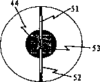
Fig. 7 shows the shape of the opaque veil that can be used for the preferred embodiments of the present invention, and this veil is united by thin rectangular band and circular central point and constituted;
Fig. 8 a and 8b are two views of the reference collection assembly of the preferred embodiments of the present invention, and this reference collection assembly is made of foveal reflex device and two reference collection fibers, and it is positioned at the front of opaque veil;
Fig. 9 is a system diagram of the present invention, and it is made of the opto-mechanical head that is separated, photoelectric subassembly and prolongation cable, shows the electronic processing circuit that is used for the compensation optical system efficiency losses and the block diagram of signal flow;
Figure 10 a and 10b are sectional views, respectively along tubular axis with vertical with tubular axis, show another kind of embodiment of the present invention, it is made of amended lasso and single coupled lens, this amended lasso has the facet with optical system axis polishing at an angle, this single coupled lens is provided to focus on delivery beams, and remains on that chief ray is parallel to optical axis in the pipeline fragment;
Figure 11 a and 11b are sectional views, vertical with tubular axis respectively and along optical system axis, show an alternative embodiment of the invention, provide second to compile optical system, with the light of guiding, so that the amplitude of detected light signal is used to determine the size of scattering particle with large angle scattering;
And Figure 12, show the another kind of embodiment of the system of the optical collection shown in Figure 12, wherein second compiles optical system and first and compiles the optical system axis conllinear.
Embodiment
Optical flow meter according to the preferred embodiment structure has been shown among Fig. 3, and it is used for determining by the speed of measuring the small-particle that is carried by fluid stream the flow rate of ducted fluid.This flowermeter is by constituting with lower member: be inserted in opto-mechanical 10 between the adjacent ribs 11 in the pipeline 12, comprise the electro-optical package 13 of two lasing light emitters 14, two scattered signal photoelectric detectors 54 and 55, handle electronic installation 15, and the optics that photoelectric subassembly 13 is connected to opto-mechanical 10 is prolonged cable duct 16.In this configuration, photoelectric subassembly 13 can be positioned at a distance, so that do not have electromotive force at opto-mechanical 10 place, this is may be because spark or short circuit and suit the requirements when being lighted through the fluid (for example rock gas) of piping.In addition, the fiber optics termination at opto-mechanical 10 place is compact, healthy and strong and is stable from size, and this is because they are away from from the thermal load of electronic installation and light source.
An opto-mechanical of the preferred embodiment that in Fig. 4, is shown in further detail 10, constitute by rigidity plate-like carriage 17, this rigidity plate-like carriage 17 can be sandwiched between the ducted flange, it has centre-drilling hole 18, the diameter of this centre-drilling hole 18 and bore approximate match, thereby form the passage of continual sealing, flow through uninterruptedly for fluid.Centre-drilling hole 18 comprises two windows 19 and 20: carry window 19 to allow delivery beams 21 and 22 to enter centre-drilling hole 18; The collection window 20 that is arranged in the opposite side of centre-drilling hole 18 allows without the light beam 23 of scattering and 24 and can both enter into collection aperture 27 through the light beam 25 and 26 of scattering.In a preferred embodiment, window 19 and 20 shape are all mated the cylindrical curvature of centre-drilling hole 18, forming the surface of smooth and continuous, so that the interference minimum that fluid flow causes, and reduce the accumulation that may be present in the pollutant in the fluid stream.In another embodiment, one section internal diameter roughly with the optics of tube wall internal diameter coupling on transparent tubing can be inserted in the centre-drilling hole 18 of plate-like carriage 17, flow with fluid-encapsulated, and allow light to enter and leave pipeline to flow.
D=d
d*f
do/f
dc
Wherein D is the axial spacing between the focus in the pipeline; d
dIt is the axial spacing between optical fiber 33 and 34; f
DoIt is the focal length of carrying object lens 38; f
DcIt is the focal length of carrying coupled lens 37.
In a preferred embodiment, carry the optical path separation between coupled lens 37 and the object lens 38 to be selected as equaling its focal length sum.This has formed telecentric optical system alleged in this area, this means that the chief ray at place, focal plane keeps with optical axis parallel.Delivery beams 21 and 22 is by along paralleling with the axle 32 of optical system and with tubular axis 36 and carry the surperficial perpendicular axle of window 19 to throw, shown in Fig. 5 a.This is very important in the application that the refractive index of the coercible gas such as rock gas changes according to internal pressure.Under the situation of non-telecentric system, the spacing between the focus will change owing to the caused parallax of the variations in refractive index of compressible fluid, thereby produces data noise.
With reference to figure 5a, cylindrical lens 41 is placed in the delivery lens system 28, so that beam focus departs from prime focus 39 and 40, focuses on 42 and 43 so that form along two secondary wire of optical system axis 32.Its effect is that the width of light beam at prime focus 39 and 40 places is widened is two light, thus the area of section that the measured zone place intercepting fluid of pushing the speed flows.In a preferred embodiment, the focal length of cylindrical lens 41 is selected as making the common point place of two light beams on optical system axis 32 to form the line focus 42 and 43 of two conllinear, and these two line focuss are positioned on the surface of collection window 20 or after the surface.
At secondary focusing 42 and 43 places, incident be minimum value without the delivery beams 23 of scattering and 24 area of section.Be oriented to intercept major part or all delivery beams 23 and 24 near thin light beam opaque veil 44 on the optics of the section at secondary focal plane place rectangular shape, that size is slightly larger than without scattering without scattering.This has allowed the light through scattering of maximum to enter the collection aperture 27 of not crested, to optimize optical signal detection sensitivity.More specifically, the beam profile of the minimum zone that the narrow dimension of the opaque veil 44 of rectangle is surrounded has allowed the low-angle as far as possible light 25 and 26 through scattering to enter collection aperture 27, and does not have from without the light beam 23 of scattering and 24 deviation.
Return with reference to figure 4, the collection lens system 45 of preferred embodiment is comprised in and carries relative and compiling in the lens bore 46 of doubling roughly of lens bore 29, and it radially extends to the neighboring of opto-mechanical plate-like carriage 17 from collection window aperture 27.With reference to figure 6a and 6b, for more clear, the size of collection lens system 45 is illustrated as exaggerating to some extent with respect to the cross section of pipeline, and it compiles coupled lens 48 by object lens 47 and optical fiber and constitutes.The light beam 25 and 26 through scattering that enters collection aperture 27 is focused in two corresponding scatter collection fibers 49 and 50, and these two optical fiber are positioned at the focus place, and corresponding in the prime focus in the centre-drilling hole 18 39 and 40 each.The size of scatter collection fibers 49 and 50 inner core diameter can be accepted through the light beam 25 of scattering and 26 major part, and these light beams 25 and 26 through scattering are the dot generation from the mating plate width of speed measured zone, as shown in the formula determining:
W=w
c*f
co/f
cc
Wherein W is the width of accepting scattered field at prime focus 39 and 40 places; w
cIt is the inner core diameter of scatter collection fibers 49 and 50; f
CoIt is the focal length that compiles object lens 47; f
CcIt is the focal length of the burnt coupled lens 48 of remittance.
The depth of focus of optical system is determined the length of velocity survey zone along optical system axis 32, and it is subjected to the influence of the depth of focus of the length of beam waist of delivery beams 21 and 22 and collection lens system 45.Two parameters all are to select lens to adjust by the constraint that provides more than the basis, but have the restriction that physics is big or small and shell sizes is applied by element.The depth of focus that optical system provides also is subjected to the influence of the size and the shape of opaque veil 44.In some cases, wish to reduce the depth of focus of collection lens system 45, with the scope of further restriction scatterometry zone along optical axis 32.This can realize by the size that increases the opaque veil 44 in optical axis 32 centers, thereby forms such shape, and this shape is made of overlapping circular central point on the rectangle band-like portions, as shown in Figure 7.
In a further advantageous embodiment, the second pair of reference collection fibers 51 and 52 is oriented to adjacent opaque veil 44 fronts, and the device that is used to be coupled from without the light of the light beam 23 of scattering and 24 is provided, shown in Fig. 8 a and 8b.Foveal reflex device 53 is placed on the center of veil 44, this foveal reflex device 53 is directed in corresponding reference optical fiber 51 or 52 without the light beam 23 of scattering or a part of 24 each incident, and the route of reference optical fiber 51 and 52 is arranged to be positioned at after the long limit of the banded opaque veil 44 of rectangle, and outside the peripheral openings of compiling lens bore 46.The signal rank that is generated by the light beam 23 and 24 without scattering that is coupled in reference optical fiber 51 and 52 can be used for monitoring the bulk strength of incident light, this bulk strength may reduce along with the time, this is that perhaps the variation by the intensity of light source is caused because of the contaminant accumulation of make dirty optical window 19 (not shown) and 20.
With reference to figure 9, scatter collection fibers 49 and 50 and reference collection fibers 51 and 52 and delivery optical fiber 33 and 34 flock together, and be enclosed in the public prolongation cable duct 16 that is connected to photoelectric subassembly 11, this photoelectric subassembly may be positioned at opto-mechanical 10 at a distance of certain distance.Collection fibers 49 and 50 and 51 and 52 is coupled to corresponding scattered signal photoelectric detector 54 and 55 and reference signal photoelectric detector 56 and 57.When particle is regional through velocity survey, be coupled in scatter collection fibers 49 and 50 and be transferred to the photogenerated electric pulse of scattered signal photoelectric detector 54 and 55, and provide processing electronic installation 15, be used for by making relevantly, determine the time that stroke postpones with 55 electric signal from two scattered signal photoelectric detectors 54.The reference signals that generated by reference light photodetector 56 and 57 can be used for adjusting the gain of scatter detector circuit 60, with the dirty dirty light signal loss that cause of compensation owing to optical window 19 and 20.
In the of the present invention another kind of embodiment shown in Figure 10 a and the 10b, heart delivery lens system 28 far away provides conveying coupled lens 61 (can be compound lens) and has had the amended lasso 62 of two facets 63 and 64, these two facets are to be polished on the surface of lasso 62, and identical with respect to the inclined degree of optical system axis 32.The delivery beams 21 and 22 that produces is being left delivery optical fiber 33 and had been refracted into certain angle at 34 o'clock, and intersect at distance and the optical axis 32 of carrying coupled lens 61 fronts to equal its focal length, aim at thereby produce the same heart far away with compacter optical arrangement.
Still with reference to figure 10a and 10b, cylindrical delivery coupled lens 65 also can be added in the delivery lens system 28, is positioned at after the optical fiber ferrule 62, with calibration delivery beams 21 and 22 on transverse axis.This has allowed independently to control the width of mating plate at prime focus 39 and 40 places by selecting the focal length of cylindrical delivery lens 65.The focal length of cylindrical objective lens 41 also must be shortened Jiao's skew that (negative lens) introduced with compensation cylindrical delivery lens 65, so as secondary focusing 42 and 43 and opaque obscuration plane 44 be consistent.
In an alternative embodiment of the invention shown in Figure 11, secondary collection lens system 66 is placed in after the 3rd optical window 67 in the 3rd in the opto-mechanical plate-like carriage 17 boring 68, and this secondary collection lens system 66 is illustrated as taking and the perpendicular angle of the optical system axis 32 of conveying and main collection lens system 28 and 45.Secondary collection lens system 66 does not comprise any veil or reference optical fiber, but can be identical with main collection lens system 45.The second pair of collection fibers 69 and 70 is placed with the light of accepting to be coupled in the secondary collection hole 71 through scattering, and this is connected to second pair of measuring photodetector (not shown) to collection fibers 69 and 70.Depend on the size of scattering particle strongly with respect to the light quantity of the large angle scattering of optical system axis 32,, can determine information about the size of the entrained scattering particle of fluid stream therefore by the ratio of measuring light signal intensity.
An alternative embodiment of the invention shown in Figure 12 provides second collection lens system 72, and it has the hole 73 that compiles the hole of system 27 greater than first, and two systems are placed with conllinear.Second collection lens system 72 will collect in the light than large angle scattering in the solid angle by the difference institute limit between the hole 73 and 27 of two systems.The information of relatively providing of the light quantity that each system compiled about particle size and shape.
Claims (16)
1. one kind is used to measure the device of the entrained particle's velocity of the fluid of pipeline of flowing through, and comprising:
(a) at least one light source and the device that is used to generate two light beams that are separated;
(b) first transparent optical window in the tube wall, its with fluid flow restriction in described pipeline, and allow described light beam enter the pipe in the space;
(c) has the optics induction system of optical axis, it guides described two light beams through described first optical window, so that described light beam forms two focuses in described pipeline, these two focuses roughly same position place in pipeline section are aimed at, but be positioned at the difference place on the tubular axis, and spacing therebetween is known;
(d) second transparent optical window in the described tube wall, it roughly is arranged in a described tube wall side opposite with described first optical window, its with fluid flow restriction in described pipeline and allow light leave the pipe in the space;
(e) at least one measuring light detector means is used to detect the light of the particle institute scattering of being carried by described fluid, and becomes the light amplitude when detected and convert corresponding measurement electronic signal to;
(f) optical collection system, it has and the optical axis of the described optics induction system optical axis of conllinear roughly, the light of the particle institute scattering that it will carry in will being flowed by fluid collects in first solid angle relative with described focus, and described light through scattering is focused on the described measuring light detector means;
(g) be used to absorb opaque veil without the light of scattering, it roughly is positioned at after the above focus of described optical axis, described veil makes second solid angle relative with described focus, this second solid angle is less than described first solid angle, so that arrive described measuring light detector means through the described light through scattering without shaded portions of described first solid angle; And
(h) electronic processing device, it receives by the detected described measurement electronic signal of described optical detector device, wherein said measurement electronic signal is processed, the time that postpones with the stroke of determining through the particle of described two focuses, and the device that is used to calculate particle rapidity or fluid flow rate.
2. equipment according to claim 1, wherein said light source is made of one or more laser instruments.
3. equipment according to claim 1, the wherein said device that is used for generating described two light beams comprise described light source are coupled at least one optical fiber.
4. equipment according to claim 1, wherein said optical detector device is made of the optical fiber that is coupled to photoelectric detector.
5. equipment according to claim 1, wherein said optical detector device comprises the first and second photodetector fields, the described first and second photodetector fields are aimed at so that be coupled to the described first photodetector field from the light of the described first focus scattering, and are coupled to the described second photodetector field from the light of the described second focus scattering.
6. equipment according to claim 5, wherein said optical detector device comprise first and second collection fibers that are coupled to corresponding first and second optical detector devices.
7. equipment according to claim 1, the optical axis and the flow direction approximate vertical of wherein said optics induction system and described optical collection system.
8. equipment according to claim 1, the chief ray of each in wherein said two light beams and the axle approximate vertical of described pipeline, if so that the variations in refractive index of described fluid, described chief ray can not depart from.
9. equipment according to claim 1, the mechanical carriage that wherein has the center pit of size and the described pipeline section of shape approximate match is inserted in the described pipeline, and partly match with the pipe front and rear, so that form continuously and the passage of sealing flows through for fluid, described mechanical carriage comprises described first and second windows, described optics induction system and described optical collection system.
10. equipment according to claim 1, wherein said first and second windows have the inside surface that is cylinder basically, roughly mate with the surface of inner tubal wall.
11. equipment according to claim 1, wherein said first and second windows are replaced by one section transparent pipe, the internal diameter of described transparent pipe mates the internal diameter of described pipeline, so that described fluid is limited in the described pipeline, and allow light to enter and through the optical collection system from the optics induction system.
12. equipment according to claim 1, wherein said optics induction system comprises the cylinder optical lens device, is used for enlarging the width of described focus on the plane of tube section.
13. equipment according to claim 12, wherein said cylindrical lens device roughly produces secondary focus at described opaque obscuration plane place, so that described light beam forms a pair of focusing line segment, the axle of described focusing line segment is mobile parallel with pipeline, and the center of the described optical system axis of process.
14. equipment according to claim 1, wherein provide and be used to intercept the device of a part without the light of scattering, this device is positioned at before the described opaque veil but after described second optical window, what it will be truncated to couples light at least one reference detector device, and utilize detected light level to adjust the gain of described photoelectric detector, so that the variation of compensation incident intensity.
15. equipment according to claim 1, the second optical collection system wherein is provided, it has second and compiles axle, this second compile the axle with described conveying optical axis and described first compile the axle in same plane, and intersect with described focus, wherein be coupled in second optical detector device by the light of the particle institute scattering in the fluid stream, so that by the amplitude ratio that more detected first light signal and detected second light detect, analyze the size and/or the shape of the particle of in fluid stream, advancing.
16. equipment according to claim 15, the described axle of the wherein said second optical collection system and the described first optical collection axle be conllinear roughly, and the wherein said second optical collection system has the big optical aperture than the described first optical collection system, and this has allowed to compile the more scattered light of large scattering angle.
Applications Claiming Priority (3)
| Application Number | Priority Date | Filing Date | Title |
|---|---|---|---|
| CA2,439,242 | 2003-09-03 | ||
| CA002439242A CA2439242C (en) | 2003-09-03 | 2003-09-03 | Optical flow meter for measuring gases and liquids in pipelines |
| PCT/CA2004/001593 WO2005022170A1 (en) | 2003-09-03 | 2004-09-03 | Optical flow meter for measuring gases and liquids in pipelines |
Publications (2)
| Publication Number | Publication Date |
|---|---|
| CN1846137A true CN1846137A (en) | 2006-10-11 |
| CN1846137B CN1846137B (en) | 2010-09-08 |
Family
ID=34230701
Family Applications (1)
| Application Number | Title | Priority Date | Filing Date |
|---|---|---|---|
| CN200480025406XA Expired - Lifetime CN1846137B (en) | 2003-09-03 | 2004-09-03 | Optical flow meter for measuring gases and liquids in pipelines |
Country Status (9)
| Country | Link |
|---|---|
| US (1) | US7265832B2 (en) |
| EP (1) | EP1664802A4 (en) |
| JP (1) | JP4704340B2 (en) |
| CN (1) | CN1846137B (en) |
| BR (1) | BRPI0414089B1 (en) |
| CA (2) | CA2439242C (en) |
| NO (1) | NO20061490L (en) |
| RU (1) | RU2377573C2 (en) |
| WO (1) | WO2005022170A1 (en) |
Cited By (9)
| Publication number | Priority date | Publication date | Assignee | Title |
|---|---|---|---|---|
| CN100593691C (en) * | 2007-08-28 | 2010-03-10 | 烟台大学 | Photoelectric identification device for multiphase fluid |
| CN107110882A (en) * | 2014-12-22 | 2017-08-29 | 高丽大学校产学协力团 | Fluid velocity determines device |
| CN107110883A (en) * | 2014-12-22 | 2017-08-29 | 高丽大学校产学协力团 | Fluid velocity determines device |
| CN111273054A (en) * | 2018-12-05 | 2020-06-12 | 西卡西伯特博士及屈恩有限及两合公司 | Flow measuring method and flow measuring device for optical flow measurement |
| CN112867927A (en) * | 2018-10-15 | 2021-05-28 | 诺基亚技术有限公司 | Device and method for treating a fluid area |
| CN114739944A (en) * | 2022-04-12 | 2022-07-12 | 华中科技大学 | Optical metering device and method for detecting parameters of fluid with good light transmittance |
| CN116625445A (en) * | 2023-07-26 | 2023-08-22 | 上海中核维思仪器仪表股份有限公司 | Gas ultrasonic flowmeter |
| CN117031744A (en) * | 2023-10-07 | 2023-11-10 | 中国空气动力研究与发展中心超高速空气动力研究所 | Imaging optical system and method based on quartz circular tube |
| EP3821227B1 (en) * | 2018-07-10 | 2024-03-13 | Gerrit Jan Van Den Engh | System, apparatus and method for off-axis illumination in flow cytometry |
Families Citing this family (27)
| Publication number | Priority date | Publication date | Assignee | Title |
|---|---|---|---|---|
| DE102005025181A1 (en) | 2005-06-01 | 2006-12-07 | Sick Engineering Gmbh | Particle concentration measuring device and measuring method |
| US7579947B2 (en) * | 2005-10-19 | 2009-08-25 | Rosemount Inc. | Industrial process sensor with sensor coating detection |
| US7880133B2 (en) * | 2006-06-01 | 2011-02-01 | Weatherford/Lamb, Inc. | Optical multiphase flowmeter |
| GB0701558D0 (en) * | 2007-01-26 | 2007-03-07 | Insensys Oil & Gas Ltd | Fluid composition monitoring |
| US8858787B2 (en) * | 2007-10-22 | 2014-10-14 | Baxter International Inc. | Dialysis system having non-invasive fluid velocity sensing |
| DE102007054186B4 (en) * | 2007-11-14 | 2012-04-12 | Digmesa Ag | Method and device for determining the flow of a flowing liquid |
| US9388642B2 (en) * | 2008-03-05 | 2016-07-12 | Schlumberger Technology Corporation | Flexible pipe fatigue monitoring below the bend stiffener of a flexible riser |
| DE102009005800A1 (en) * | 2009-01-22 | 2010-07-29 | Dues, Michael, Dr.-Ing. | Optical flow measurement |
| US20100201984A1 (en) * | 2009-02-11 | 2010-08-12 | Cyberoptics Semiconductor, Inc. | In-line high pressure particle sensing system |
| US20100235117A1 (en) * | 2009-03-15 | 2010-09-16 | Lauris Technologies Inc | Optical Gas Flow Meter |
| US8467050B2 (en) * | 2009-06-11 | 2013-06-18 | M-I Llc | Apparatus and method for metering flare gas |
| US8567269B1 (en) | 2009-07-27 | 2013-10-29 | M-I Llc | Sensor mounting apparatus and method |
| JP5950319B2 (en) * | 2010-06-15 | 2016-07-13 | 新日本空調株式会社 | Particle concentration measuring device |
| KR20120074558A (en) * | 2010-12-28 | 2012-07-06 | 삼성전자주식회사 | Apparatus for detection of microparticle |
| US8525986B2 (en) | 2011-04-06 | 2013-09-03 | M-I Llc | Method for hydrocarbon well completion |
| US8749766B1 (en) * | 2012-04-24 | 2014-06-10 | The Boeing Company | Optical airflow sensor |
| US9383476B2 (en) | 2012-07-09 | 2016-07-05 | Weatherford Technology Holdings, Llc | In-well full-bore multiphase flowmeter for horizontal wellbores |
| US9597229B2 (en) | 2013-03-15 | 2017-03-21 | Abbott Medical Optics Inc. | Phacoemulsification flow rate detection system and method |
| KR20180101086A (en) * | 2017-03-03 | 2018-09-12 | 김태용 | Device for measuring water quality |
| CN106353534A (en) * | 2016-09-30 | 2017-01-25 | 天津市誉航润铭科技发展有限公司 | Novel pipeline flow speed detection sensor |
| CN107703327B (en) * | 2017-10-30 | 2023-05-09 | 西安工业大学 | A laser velocity measuring device for measuring liquid or gas flow velocity and its application method |
| RU179411U1 (en) * | 2018-03-01 | 2018-05-14 | Акционерное общество "ГМС Нефтемаш" | Device for measuring the flow of liquid and gas |
| KR102499008B1 (en) * | 2018-04-11 | 2023-02-10 | 사이버옵틱스 코포레이션 | inline particle sensor |
| JP7126048B2 (en) * | 2018-08-08 | 2022-08-26 | パナソニックIpマネジメント株式会社 | ultrasonic flow meter |
| DE102018122216A1 (en) | 2018-09-12 | 2020-03-12 | SIKA Dr. Siebert & Kühn GmbH & Co. KG | Flow-through tube insert for optical flow measurement |
| WO2020178641A1 (en) * | 2019-03-07 | 2020-09-10 | Flowlit Ltd. | Optical fluid flow velocity measurement |
| CA3051376C (en) | 2019-08-06 | 2020-04-28 | Surface Solutions Inc. | Methane monitoring and conversion apparatus and methods |
Family Cites Families (17)
| Publication number | Priority date | Publication date | Assignee | Title |
|---|---|---|---|---|
| US3680961A (en) * | 1970-06-01 | 1972-08-01 | British Aircraft Corp Ltd | Measurement of particle sizes |
| DE2643616C3 (en) * | 1976-09-28 | 1979-05-31 | Erwin Sick Gmbh Optik-Elektronik, 7808 Waldkirch | Flow rate meter |
| US4251733A (en) * | 1978-06-29 | 1981-02-17 | Hirleman Jr Edwin D | Technique for simultaneous particle size and velocity measurement |
| DE3347092A1 (en) * | 1983-12-24 | 1985-07-18 | MTU Motoren- und Turbinen-Union München GmbH, 8000 München | METHOD AND DEVICE FOR OPTICALLY MEASURING THE FLOW OF A FLUID |
| US4938592A (en) * | 1987-07-28 | 1990-07-03 | Amherst Process Instruments, Inc. | Beam forming and sensing apparatus for aerodynamic particle sizing system |
| US4854705A (en) * | 1988-04-05 | 1989-08-08 | Aerometrics, Inc. | Method and apparatus to determine the size and velocity of particles using light scatter detection from confocal beams |
| US4919536A (en) * | 1988-06-06 | 1990-04-24 | Northrop Corporation | System for measuring velocity field of fluid flow utilizing a laser-doppler spectral image converter |
| US4988190A (en) * | 1990-01-05 | 1991-01-29 | Trustees Of Princeton University | Absorption line filter window and method for velocity measurements by light scattering |
| US5133602A (en) * | 1991-04-08 | 1992-07-28 | International Business Machines Corporation | Particle path determination system |
| US5153665A (en) * | 1991-06-14 | 1992-10-06 | The United States Of America As Represented By The Administrator Of The National Aeronautics And Space Administration | Vaporizing particle velocimeter |
| DE4130526C2 (en) * | 1991-09-13 | 1996-09-26 | Rainer Dr Kramer | Laser time-of-flight anemometer |
| US5999256A (en) * | 1992-02-12 | 1999-12-07 | Cambridge Consultants Limited | Particle measurement system |
| US5561515A (en) * | 1994-10-07 | 1996-10-01 | Tsi Incorporated | Apparatus for measuring particle sizes and velocities |
| US5905568A (en) * | 1997-12-15 | 1999-05-18 | The United States Of America As Represented By The Administrator Of The National Aeronautics And Space Administration | Stereo imaging velocimetry |
| US6128072A (en) * | 1998-04-23 | 2000-10-03 | Nova Gas Transmission Ltd. | Optical flow meter integrally mounted to a rigid plate with direct optical access to the interior of a pipe |
| US6429926B1 (en) * | 2001-01-08 | 2002-08-06 | Nova Gas Transmission Ltd. | Optical flow meter capable of operating with a variable refractive index |
| US6794671B2 (en) * | 2002-07-17 | 2004-09-21 | Particle Sizing Systems, Inc. | Sensors and methods for high-sensitivity optical particle counting and sizing |
-
2003
- 2003-09-03 CA CA002439242A patent/CA2439242C/en not_active Expired - Lifetime
-
2004
- 2004-09-03 US US10/570,323 patent/US7265832B2/en not_active Expired - Lifetime
- 2004-09-03 WO PCT/CA2004/001593 patent/WO2005022170A1/en active Application Filing
- 2004-09-03 BR BRPI0414089A patent/BRPI0414089B1/en not_active IP Right Cessation
- 2004-09-03 EP EP04761757A patent/EP1664802A4/en not_active Withdrawn
- 2004-09-03 CN CN200480025406XA patent/CN1846137B/en not_active Expired - Lifetime
- 2004-09-03 RU RU2006108798/28A patent/RU2377573C2/en active
- 2004-09-03 CA CA002537344A patent/CA2537344A1/en not_active Withdrawn
- 2004-09-03 JP JP2006525583A patent/JP4704340B2/en not_active Expired - Fee Related
-
2006
- 2006-04-03 NO NO20061490A patent/NO20061490L/en not_active Application Discontinuation
Cited By (15)
| Publication number | Priority date | Publication date | Assignee | Title |
|---|---|---|---|---|
| CN100593691C (en) * | 2007-08-28 | 2010-03-10 | 烟台大学 | Photoelectric identification device for multiphase fluid |
| CN107110882A (en) * | 2014-12-22 | 2017-08-29 | 高丽大学校产学协力团 | Fluid velocity determines device |
| CN107110883A (en) * | 2014-12-22 | 2017-08-29 | 高丽大学校产学协力团 | Fluid velocity determines device |
| CN107110883B (en) * | 2014-12-22 | 2020-01-31 | 英泰克生物有限公司 | Fluid velocity measuring apparatus |
| EP3821227B1 (en) * | 2018-07-10 | 2024-03-13 | Gerrit Jan Van Den Engh | System, apparatus and method for off-axis illumination in flow cytometry |
| CN112867927A (en) * | 2018-10-15 | 2021-05-28 | 诺基亚技术有限公司 | Device and method for treating a fluid area |
| CN112867927B (en) * | 2018-10-15 | 2023-07-07 | 诺基亚技术有限公司 | Apparatus and method for treating a fluid region |
| US12000704B2 (en) | 2018-10-15 | 2024-06-04 | Nokia Technologies Oy | Apparatus and method for processing a fluid zone |
| CN111273054A (en) * | 2018-12-05 | 2020-06-12 | 西卡西伯特博士及屈恩有限及两合公司 | Flow measuring method and flow measuring device for optical flow measurement |
| CN114739944A (en) * | 2022-04-12 | 2022-07-12 | 华中科技大学 | Optical metering device and method for detecting parameters of fluid with good light transmittance |
| CN114739944B (en) * | 2022-04-12 | 2024-09-20 | 华中科技大学 | Optical metering device and method for detecting parameters of fluid with good light transmittance |
| CN116625445B (en) * | 2023-07-26 | 2023-09-22 | 上海中核维思仪器仪表股份有限公司 | Gas ultrasonic flowmeter |
| CN116625445A (en) * | 2023-07-26 | 2023-08-22 | 上海中核维思仪器仪表股份有限公司 | Gas ultrasonic flowmeter |
| CN117031744A (en) * | 2023-10-07 | 2023-11-10 | 中国空气动力研究与发展中心超高速空气动力研究所 | Imaging optical system and method based on quartz circular tube |
| CN117031744B (en) * | 2023-10-07 | 2023-12-15 | 中国空气动力研究与发展中心超高速空气动力研究所 | Imaging optical system and method based on quartz circular tube |
Also Published As
| Publication number | Publication date |
|---|---|
| BRPI0414089B1 (en) | 2017-01-24 |
| JP2007504464A (en) | 2007-03-01 |
| RU2006108798A (en) | 2006-09-10 |
| US20070064218A1 (en) | 2007-03-22 |
| BRPI0414089A (en) | 2006-10-31 |
| CA2439242C (en) | 2008-01-29 |
| NO20061490L (en) | 2006-06-01 |
| CN1846137B (en) | 2010-09-08 |
| WO2005022170A1 (en) | 2005-03-10 |
| RU2377573C2 (en) | 2009-12-27 |
| EP1664802A4 (en) | 2009-07-15 |
| JP4704340B2 (en) | 2011-06-15 |
| CA2537344A1 (en) | 2005-03-10 |
| EP1664802A1 (en) | 2006-06-07 |
| US7265832B2 (en) | 2007-09-04 |
| CA2439242A1 (en) | 2005-03-03 |
Similar Documents
| Publication | Publication Date | Title |
|---|---|---|
| CN1846137B (en) | Optical flow meter for measuring gases and liquids in pipelines | |
| US7673526B2 (en) | Apparatus and method of lensing an ultrasonic beam for an ultrasonic flow meter | |
| EP0952431B1 (en) | Optical flow meter | |
| EP0289200B2 (en) | Apparatus and method for particle analysis | |
| US7609368B2 (en) | Optical device and method for sensing multiphase flow | |
| US4917496A (en) | Particle size measuring instrument with direct scattered light detection | |
| US7911591B2 (en) | Optical transit time velocimeter | |
| US6465802B1 (en) | Particle measurement apparatus flow cell useful for sample fluids having different refractive indexes | |
| JP2022529308A (en) | Optical fluid velocity measurement | |
| GB2035547A (en) | Measuring fluid flow photoelectrically | |
| WO2021099081A1 (en) | Optical based particulate matter sensing | |
| MXPA06002432A (en) | Optical flow meter for measuring gases and liquids in pipelines | |
| JPS5868645A (en) | Method for measuring concentration of particles | |
| KR101836674B1 (en) | Mutiaxis laser Doppler velocimeter for fluid velocity visualization | |
| RU2069315C1 (en) | Method of optical measurement of gas stream discharge by laser flowmeter | |
| CN1207172A (en) | Device for measuring the concentration of airborne fibers | |
| MXPA06005448A (en) | Optical device and method for sensing multiphase flow |
Legal Events
| Date | Code | Title | Description |
|---|---|---|---|
| C06 | Publication | ||
| PB01 | Publication | ||
| C10 | Entry into substantive examination | ||
| SE01 | Entry into force of request for substantive examination | ||
| C14 | Grant of patent or utility model | ||
| GR01 | Patent grant | ||
| CX01 | Expiry of patent term |
Granted publication date: 20100908 |
|
| CX01 | Expiry of patent term |