CN1784631A - Vehicle rearview mirror components and assemblies with these components installed - Google Patents
Vehicle rearview mirror components and assemblies with these components installed Download PDFInfo
- Publication number
- CN1784631A CN1784631A CN 200480012149 CN200480012149A CN1784631A CN 1784631 A CN1784631 A CN 1784631A CN 200480012149 CN200480012149 CN 200480012149 CN 200480012149 A CN200480012149 A CN 200480012149A CN 1784631 A CN1784631 A CN 1784631A
- Authority
- CN
- China
- Prior art keywords
- mirror
- mirror element
- substrate
- electro
- substantially transparent
- Prior art date
- Legal status (The legal status is an assumption and is not a legal conclusion. Google has not performed a legal analysis and makes no representation as to the accuracy of the status listed.)
- Granted
Links
Images


Landscapes
- Electrochromic Elements, Electrophoresis, Or Variable Reflection Or Absorption Elements (AREA)
- Rear-View Mirror Devices That Are Mounted On The Exterior Of The Vehicle (AREA)
Abstract
Description
相关申请的交叉参考Cross References to Related Applications
本申请是以下专利申请的部分继续,所述专利申请为:作为在2004年4月1日发表的美国专利申请U.S.Patent ApplicationNo.US2004/0061920A1的、于2002年9月30日提出的标题为“ELECTROCHROMIC DEVICES HAVING NO POSITIONALOFFSET BETWEEN SUBSTRATES”(在基片之间没有位置偏移的电致变色装置)的U.S.Patent Application No.10/260,741,以及现在是美国专利U.S Patent No.6560,004的于2001年6月19日提出的标题为“COUPLED ELECROCHROMIC COMPOUNDS WITHPHOTOSTABLE DICATION OXIDATION ATATES”(具有光稳定的双阳离子氧化状态的偶合的电致白色化合物),该专利是目前是美国专利U.S.Patent No.6,249,369的1999年7月9日提出的U.S.PatentApplication No.09/350,879的继续,这些专利的全部内容在这里引用为参考文献。This application is a continuation-in-part of patent application filed September 30, 2002 as U.S. Patent Application No. US2004/0061920A1, published April 1, 2004, entitled " U.S. Patent Application No. 10/260,741 for ELECTROCHROMIC DEVICES HAVING NO POSITIONA OFFSET BETWEEN SUBSTRATES" (Electrochromic Devices Without Positional Offset Between Substrates), and now U.S. Patent No. 6560,004 issued in 2001 Titled "COUPLED ELECROCHROMIC COMPOUNDS WITHHPHOTOSTABLE DICATION OXIDATION ATATES" (Coupled Electrowhite Compounds with Photostable Dicationic Oxidation States), filed on June 19, is currently the 1999 issue of U.S. Patent No. 6,249,369 A continuation of U.S. Patent Application No. 09/350,879, filed July 9, which is hereby incorporated by reference in its entirety.
技术领域technical field
本发明总的涉及电光器件以及装有这些器件的装置。更具体地说,本发明涉及用在建筑用窗或者车辆后视镜的中电光器件。The present invention relates generally to electro-optic devices and devices incorporating these devices. More particularly, the present invention relates to electro-optical devices for use in architectural windows or vehicle rear view mirrors.
背景技术Background technique
电光元件用于各种用途,包括光闸、可变衰减滤光片、以及建筑和车辆用窗。电光元件最普遍地应用于车辆中使用的后视镜组合件中。这种电光后视镜被自动控制,响应指向后方和前方的光学传感器改变镜子的反射率,以便降低前照灯在反射到驾驶员眼睛的像中的眩光。Electro-optic components are used in a variety of applications including optical shutters, variable attenuation filters, and windows in buildings and vehicles. Electro-optic elements are most commonly used in rearview mirror assemblies used in vehicles. The electro-optical rearview mirror is automatically controlled to change the reflectivity of the mirror in response to optical sensors pointing backwards and forwards in order to reduce glare from headlights in the image reflected to the driver's eyes.
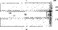
图1A表示用于典型的外部后视镜组合件中的后视镜部件5的部分的分解图。部件5包括电致变色镜元件10、边框50、和载板70(图1B)。部件可以进一步包括衬垫60和62,它们被置于电致变色镜元件10的任何一侧,设置它们的目的是围绕镜元件10的外周形成二级密封。如图1B最清楚地表示的,电致变色元件10包括基本上透明的前部元件12,该元件12典型地用玻璃形成,具有前表面12a和后表面12b。电致变色元件10进一步包括稍稍与元件12间隔开的后部元件14。在元件12和14之间、围绕它们外周形成密封件16,以便在它们之间限定出密封的腔室,向该腔室中提供电致变色介质。优选地,元件12和14在面对腔室的表面上具有导电层,以便能够跨越电致变色介质施加电位。这些电极是相互电绝缘的,并借助第一和第二总线连接器34a和34b单独地连接到电源上。为了便于总线连接器34a、34b的连接,元件12和14典型地竖直偏移,使得总线连接器可以沿着一个元件的底边固定,而另一个总线连接器可以固定到另一个元件的顶边上。总线连接器34a、34b是典型的弹簧夹,类似于公知的U.S.PatentNos.6,064,509和6,062,920中所公开的弹簧夹,以便确保它们在物理上和电学上保持结合到元件12和14的朝向内部的表面上的电极层上。一旦电致变色元件10被制成并且安装上总线夹34a、34b,就可以组装镜部件5。如图1A和1B所示,边框包括前唇缘51,该前唇缘延续到前部元件12的前表面12a的一部分上。典型地,前唇缘51延续到前表面12a的足够的部分上,以便遮蔽人对密封件的视线并保护密封件16使之免受可能的紫外线退化。如从图1B可以看出的,边框50的前唇缘51的宽度D1依赖于许多因素,其中包括元件12和14的偏移距离D2。并且,总线连接器夹34a和34b需要延伸到元件12和14的外周边缘之外,这就要求较宽的边框。典型的现有技术的边框具有宽度D1为5mm或者以上的前唇缘。Figure 1A shows an exploded view of parts of a rear
在将电致变色镜元件10插入到边框50内之前,可以在前唇缘51的后面设置可供选用的前部垫圈60,以便被压紧在前部元件12的前表面12a与边框50的前唇缘51的内表面之间。然后将镜元件10放置在边框50内,并且可以沿着元件14的后表面的外周,设置可供选用的后部垫圈62。代替装入前部和/或后部垫圈,或者除了在装入前部和/或后部垫圈之外,也可以在边框/镜的界面区域填充或者封装诸如氨基甲酸乙酯、有机硅、或者环氧树脂等密封材料。然后将典型地用工程级刚性塑料或者类似于边框50所用的材料形成的载板70,压紧到元件14的后表面上,垫圈62被压缩在它们之间。可以在边框的内部形成多个小突出部52,使得将载板70卡住就位,以便将镜元件10固定到边框内。载板70典型地用于将镜部件安装到外部镜框架上。更具体地说,可以将定位器(图57中表示为元件740)安装到镜子框架内,并机械地结合到载板70上,以便能够远距离调节镜部件在镜子框架内的位置。Before inserting the
尽管上述结构是可以容易制造的,但却引起了与电致变色镜部件的边框的前唇缘的宽度相关的外观式样方面的问题。特别是,由于需要容纳总线夹,元件12和14的位置偏移,以及遮蔽密封件的视线,边框的前唇缘的宽度典型地比用于未减光(非电光)的镜子上使用的任何边框的前唇缘的宽度都宽。在有些车辆中,只有驾驶员侧的外部镜是电光的,而乘客侧的镜子则是未减光的。Although the above structure is easily manufacturable, it raises a problem in terms of appearance in relation to the width of the front lip of the bezel of the electrochromic mirror component. In particular, the front lip of the bezel is typically wider than any used on undimmed (non-electro-optic) mirrors due to the need to accommodate bus clips, the offset position of
从而,需要改进电光的外部镜部件,使之减小边框的前部宽度,或者根本就不包含前边框。Accordingly, there is a need for an improved electro-optic exterior mirror assembly that reduces the front width of the bezel, or does not include a front bezel at all.
进而,在车辆应用中,对于内部和外部、驾驶员侧和乘客侧、以及前视镜而言,电光后视镜元件变得越来越普遍。当装入到车辆后视镜组合件中时,典型的电光元件将具有有效的视场,该视场小于被元件本身的周长限定的区域。有效的视场主要受到元件本身的结构和/或相关的边框的限制。Furthermore, in vehicle applications, electro-optic mirror elements are becoming more and more common for interior and exterior, driver's and passenger's side, and front-view mirrors. When incorporated into a vehicle rearview mirror assembly, a typical electro-optic element will have an effective field of view that is smaller than the area defined by the perimeter of the element itself. The effective field of view is primarily limited by the construction of the component itself and/or the associated bezel.
进行过各种尝试,以便提供一种具有基本上等于由其周边限定的区域的有效视场的电光元件。也提出了装有这些元件的组合件的方案。Various attempts have been made to provide an electro-optical element having an effective field of view substantially equal to the area defined by its periphery. Assemblies incorporating these elements have also been proposed.
所需要的是提供一种改进的电光镜部件。在装入这种改进过的电光镜部件的组合件中,也需要改进。What is needed is an improved electro-optic mirror assembly. Improvements are also needed in assemblies incorporating such improved electro-optic mirror components.
发明的内容content of the invention
在本发明的一个方面中,用于车辆的电光后视镜包括电光镜部件,该电光镜部件包括在它们之间限定出腔室的前部元件和后部元件,并且具有配备在所述腔室内的电光材料。托架,该托架支承着该电光镜部件。围绕着电光镜部件的外周配置边框,并且具有延续到前部元件的前表面的部分上的前唇缘,并具有延伸到托架的边缘上的后唇缘,后唇缘被固定到托架的边缘上。In one aspect of the present invention, an electro-optic rearview mirror for a vehicle includes an electro-optic mirror assembly including a front element and a rear element defining a cavity therebetween, and has a Indoor electro-optic materials. A bracket supporting the electro-optical mirror component. A bezel is configured around the periphery of the electro-optic mirror assembly and has a front lip continuing to a portion of the front surface of the front element, and has a rear lip extending to an edge of the bracket, the rear lip being secured to the bracket on the edge.
在本发明的另一个方面中,用于车辆的后视镜包括电光镜部件,该电光镜部件包括在它们之间限定出腔室的前部元件和后部元件,并且具有配备在所述腔室内的电光材料。托架,该托架支承着该电光镜部件。边框,该边框围绕着电光镜部件的外周配置,并具有延续和结合到前部元件的前表面的边缘部分上的前唇缘,并进一步具有从前唇缘至少部分地沿着电光镜部件的侧面延伸的侧凸缘。In another aspect of the present invention, a rearview mirror for a vehicle includes an electro-optical mirror assembly including a front element and a rear element defining a cavity therebetween, and having a Indoor electro-optic materials. A bracket supporting the electro-optical mirror component. A bezel configured around the periphery of the electro-optic mirror part and having a front lip that continues and is joined to an edge portion of the front surface of the front element, and further has a front lip at least partially along a side of the electro-optic mirror part Extended side flanges.
在本发明的另一个方面中,用于车辆的后视镜组合件包括镜子框架,该镜子框架限定出一个内部和一个前部开口,并具有安装于其内的定位装置。镜子元件和支承该镜子元件的托架被安置在前部开口内并被可操作地安装到定位装置上,用于角度调整。围绕镜子元件的外周配置边框。该边框具有横向延伸的翅,该翅滑动地与镜子框架的内表面结合,用于将内部封闭,以防止看到镜子框架的内部。In another aspect of the invention, a rearview mirror assembly for a vehicle includes a mirror frame defining an interior and a front opening and having a positioning device mounted therein. A mirror element and a bracket supporting the mirror element are positioned within the front opening and are operatively mounted to the positioning means for angular adjustment. A bezel is arranged around the periphery of the mirror element. The bezel has laterally extending fins that slideably engage the inner surface of the mirror frame for sealing the interior from viewing the interior of the mirror frame.
在本发明的另一个方面中,用于车辆的可变反射率镜包括镜部件。边框,该边框围绕镜部件的外周配置并安装于其上,该边框具有横向延伸的柔性翅,该柔性翅在外侧横向方向上延伸,该翅适合于柔性地结合到镜子框架的内表面上,用于封闭内部空间以防止看到镜子框架的内部。In another aspect of the invention, a variable reflectivity mirror for a vehicle includes a mirror component. a frame disposed around the periphery of the mirror component and mounted thereto, the frame having laterally extending flexible wings extending in an outer lateral direction, the wings being adapted to be flexibly bonded to the inner surface of the mirror frame, Used to enclose an interior space to prevent seeing inside the mirror frame.
在本发明的另外一个方面中,车辆用的电光可变反射率镜包括前部元件,该前部元件具有前表面和后表面,该后表面具有配置在其上的导电材料的第一层。该镜进一步包括后部元件,该后部元件具有前表面和后表面,后部元件的前表面具有导电材料配置于其上的第二层。设置密封件,可密封地将所述元件以彼此间隔开的关系结合在一起,以便限定出一个腔室。将电光材料配置在所述腔室内。基本上不透光的材料制的条带配置在前部元件的后表面上,该条带沿着其边缘配置,并围绕其外周延伸。In another aspect of the invention, an electro-optic variable reflectivity mirror for a vehicle includes a front element having a front surface and a rear surface with a first layer of conductive material disposed thereon. The mirror further includes a rear element having a front surface and a rear surface, the front surface of the rear element having a second layer of conductive material disposed thereon. A seal is provided to sealably couple the elements together in spaced relation to each other so as to define a chamber. An electro-optic material is disposed within the chamber. A strip of substantially opaque material is arranged on the rear surface of the front element, the strip is arranged along its edge and extends around its periphery.
本发明的另一个方面,提供一种用于车辆的电致变色后视镜,包括框架,电致变色镜部件和边框。电致变色镜部件包括前部和后部元件,在前部和后部元件之间限定成一个腔室,将电致变色材料配置在该腔室内。前部元件具有前表面和限定该前表面的边缘。一个边框覆盖前部元件的边缘,但是在该前表面上延伸小于1mm。Another aspect of the present invention provides an electrochromic rearview mirror for a vehicle, including a frame, an electrochromic mirror component and a frame. The electrochromic mirror assembly includes front and rear elements defining a chamber between the front and rear elements within which the electrochromic material is disposed. The front element has a front surface and an edge defining the front surface. A bezel covers the edge of the front element, but extends less than 1mm over the front surface.
本发明的另外一个方面,提供一种镜子元件,该镜子元件包括基本上透明的第一基片和第二基片,其中,所述第一基片包括在其至少一个表面上的基本上透明的导体并具有第一电触点,所述第二基片包括一个在其表面上的至少部分反射的导体并具有第二电触点,其中,第一和第二触点在镜子元件的边缘上限定出基本上连续的部分。In another aspect of the present invention, there is provided a mirror element comprising a substantially transparent first substrate and a second substrate, wherein the first substrate comprises a substantially transparent substrate on at least one surface thereof. and having a first electrical contact, said second substrate comprising an at least partially reflective conductor on its surface and having a second electrical contact, wherein the first and second contacts are at the edge of the mirror element The upper limit defines a substantially continuous portion.
本发明的进一步的一个方面,提供一种镜子元件,该镜子元件包括基本上透明的第一基片和第二基片,其中,所述第一基片包括围绕着基本上透明的第一基片的至少一个表面的周边的至少部分反射的环,第二基片至少在一个表面上包括至少部分反射的导体,其中,至少部分反射的导体的反射率和至少部分反射的环的反射率基本上相同。In a further aspect of the present invention, there is provided a mirror element comprising a substantially transparent first substrate and a second substrate, wherein the first substrate comprises a substrate surrounding the substantially transparent first substrate. An at least partially reflective ring on the periphery of at least one surface of the sheet, the second substrate includes at least a partially reflective conductor on at least one surface, wherein the reflectivity of the at least partially reflective conductor and the reflectivity of the at least partially reflective ring are substantially same as above.
本发明的另外一个方面,提供一种镜子元件,该镜子元件包括基本上透明的第一基片和第二基片,它们经由密封件以彼此间隔开的关系相互固定,以限定成一个腔室,其中,密封件基本上是透明的,基本上透明的第一基片靠近其周围部分包括光谱过滤器材料。In another aspect of the present invention, there is provided a mirror element comprising substantially transparent first and second substrates secured to each other in spaced relation to each other via a seal to define a cavity , wherein the sealing member is substantially transparent, and the substantially transparent first substrate comprises a spectral filter material near its periphery.
本发明的另一个方面,提供一种镜组合件,包括基本上透明的第一基片和第二基片,所述第一基片在其至少一个表面上包括基本上透明的导体,并具有第一电触点,所述第二基片在其至少一个表面上包括至少部分反射的导体并具有第二电触点,其中,结合起来的第一和第二电触点所占据的长度,在由镜子元件的外周限定的总长度的约0.5倍以下。In another aspect of the present invention, there is provided a mirror assembly comprising a substantially transparent first substrate and a second substrate, the first substrate comprising a substantially transparent conductor on at least one surface thereof, and having a first electrical contact, said second substrate comprising an at least partially reflective conductor on at least one surface thereof and having a second electrical contact, wherein the length occupied by the combined first and second electrical contacts is, Below about 0.5 times the overall length defined by the periphery of the mirror element.
本发明的再一个方面,提供一种镜子元件,包括基本上透明的第一基片,该第一基片在其第二个表面上包括低表面电阻的导体,其中,低表面电阻导体具有约1.0Ω/□到约10Ω/□的表面电阻。Still another aspect of the present invention provides a mirror element comprising a substantially transparent first substrate comprising a conductor of low surface resistance on its second surface, wherein the conductor of low surface resistance has about Surface resistance of 1.0Ω/□ to about 10Ω/□.
本发明的另一个方面,提供一种镜子元件,包括基本上透明的基片,该基片包括具有可变表面电阻的电导体,其中,表面电阻在靠近相关的电触点处比较低,与离开触点的距离成正比,表面电阻变得越来越高。In another aspect of the present invention, there is provided a mirror element comprising a substantially transparent substrate comprising electrical conductors having a variable surface resistance, wherein the surface resistance is lower near an associated electrical contact, and Proportional to the distance from the contact point, the sheet resistance becomes higher and higher.
本发明的另外一个方面,提供一种镜子元件,包括基本上透明的第一基片,该基片在其第二个表面上包括基本上透明的导体,并进一步包括第一周边长度。该镜子元件进一步包括第二基片,该基片包括第二周边长度并进一步包括电导体,该电导体具有约0.05Ω/□和约8.0Ω/□之间的表面电阻,其中,第一周边长度大于第二周边长度。In another aspect of the present invention, there is provided a mirror element comprising a first substantially transparent substrate including a substantially transparent conductor on a second surface thereof, and further comprising a first perimeter length. The mirror element further includes a second substrate comprising a second perimeter length and further comprising an electrical conductor having a sheet resistance between about 0.05Ω/□ and about 8.0Ω/□, wherein the first perimeter length greater than the second perimeter length.
本发明的再一个方面,提供一种镜子元件,包括基本上透明的第一基片和第二基片,所述第一基片在其第二个表面上包括基本上透明的导体,并进一步包括第一周边长度,基本上透明的第一基片进一步包括小于2.0mm的厚度,第二基片包括第二周边长度,并进一步包括电导体。Still another aspect of the present invention provides a mirror element comprising a substantially transparent first substrate and a second substrate, the first substrate comprising a substantially transparent conductor on its second surface, and further Including the first perimeter length, the substantially transparent first substrate further includes a thickness of less than 2.0 mm, the second substrate includes a second perimeter length, and further includes an electrical conductor.
本发明的进一步的方面,提供一种镜子元件,包括基本上透明的第一基片,该基片具有小于2.0mm的厚度,该基本上透明的第一基片在靠近其外周的部分上包括有基本上不透明的材料。A further aspect of the present invention provides a mirror element comprising a substantially transparent first substrate having a thickness of less than 2.0 mm, the substantially transparent first substrate comprising There are substantially opaque materials.
本发明的另一个方面,提供一种电光后视镜元件,包括第一基片和第二基片,第一基片至少在靠近其第二个表面的部分上有材料的第二表面叠层,所述第二基片在至少靠近其一个表面的部分上具有材料的第二基片叠层,其中,材料的第二表面叠层所具有的b*值,低于材料的第二基片叠层的b*值。Another aspect of the present invention provides an electro-optical rearview mirror element, comprising a first substrate and a second substrate, the first substrate has a second surface lamination of materials at least on a portion close to its second surface , the second substrate has a second substrate stack of material on at least a portion close to one of its surfaces, wherein the second surface stack of material has a b * value lower than that of the second substrate of material The b * value of the stack.
本发明的再一个方面,提供一种电光后视镜元件,包括基本上与第二表面导电电极的第二部分电绝缘的第二表面导电电极的第一部分。In yet another aspect of the present invention, there is provided an electro-optic rearview mirror element comprising a first portion of a second surface conductive electrode substantially electrically insulated from a second portion of the second surface conductive electrode.
本发明的进一步的一个方面,提供一种电光后视镜元件,包括第一基片和第二基片。第一基片至少在靠近第一表面的部分处具有材料的亲水叠层,第一基片至少在靠近第二表面的部分处进一步包括第一导电电极、光谱过滤器材料和增附材料。第二基片至少在靠近第三表面部分处具有第二导电电极,反射材料和保护涂敷材料。A further aspect of the present invention provides an electro-optic rearview mirror element, including a first substrate and a second substrate. The first substrate has a hydrophilic stack of materials at least in a portion proximate to the first surface, and the first substrate further includes a first conductive electrode, a spectral filter material, and an adhesion promotion material at least in a portion proximate to the second surface. The second substrate has a second conductive electrode, a reflective material and a protective coating material at least proximate the third surface portion.
本发明的另一个方面,提供一种电光后视镜元件,包括第一基片和第二基片,两种基片以彼此间隔开的关系经由包括间隔件的主密封材料相互固定在一起,其中,材料的第二表面叠层基本上没有与间隔件相关的扭曲的区域。Another aspect of the present invention provides an electro-optic rearview mirror element, comprising a first substrate and a second substrate, and the two substrates are fixed to each other in a spaced relationship via a main sealing material comprising a spacer, Wherein the second surface stack of materials is substantially free of regions of spacer-related distortion.
在至少一个实施例中,提供一种电光元件,包括前部和后部基片,所述基片除了凹入的或者为了方便与相关的导电敷层接触而设有小突出部的边缘的部分之外,具有基本上平行的外周。在至少一个相关的实施例中,前部基片的“第二表面”设有一个或者多个基本上透明的高导电性材料的导电层。在至少一个另外的实施例中,后部基片的“第三表面”设有一个或多个高导电性的层;前部元件的第二表面也可以具有一个或多个高导电性的导电层。在至少另外一个相关的实施例中,该元件安装到托架上,该托架只在靠近与导电敷层接触的触点相关联的边缘处具有整体边框。在至少另外一个实施例中,元件在第一或第二表面之一上设置有围绕前部基片的外周的至少部分不透明的敷层,使得不能看到相关的密封件。在至少一个相关的实施例中,外周敷层具有基本上与反射元件的剩余部分的反射率基本上匹配的反射率。在另外一个相关的实施例中,外周敷层是光谱过滤器,该光谱过滤器基本上阻挡紫外线和/或红外线照射到相关的密封件上;与在其第一或第二表面上的敷层相反,可以将该光谱过滤器装入到对应的基片内。如果将诸如反射材料的敷层围绕镜子的周边涂敷到第一或第二表面上以便遮盖密封件和/或接触区域时,敷层的反射的颜色变得很重要。典型地,希望产生一种在可见光谱区是中性的或者基本上均匀的颜色,或者产生一种与明澈的或者被漂白的状态的镜子元件的剩余部分的颜色相匹配的反射颜色。当将这种敷层涂敷到透明导体上方的第二表面上时,当从前方观察时,敷层的表观颜色受到透明导体的光学性质的影响。该颜色可以通过选择用于制造透明导体的材料和材料的厚度加以控制。如果需要颜色的中性,在沉积透明导体时可以利用颜色抑制层,或者可以采用非常厚的导体,这种厚(约3个波长或者以上)的导体固有的性质是含彩色量很低。或者,可以在沉积透明导体之前在第一基片的第二表面上涂敷周边敷层。如果第二表面外周敷层是黑色或者实质上着色的话,也可以应用所有上面所述的使透明导体对色彩的贡献降低到最低的技术。作为一个例子,第一表面铬沉积物的测色为,a*为-0.99以及b*为+0.24,敷层具有约65%的反射率。一个例示的电致变色外部镜的测色为,a*为-2.1,b*为+3.1的,反射率约为58%。在该例子中,可以在视觉上观察到反射率的差别,但是,对于大多数应用来说,这种反射率的匹配是可以接受的。在周边反射器和主反射器之间的反射率的差别小于10%是优选的,而在周边反射器与主反射器之间的反射率的差别小于5%是最优选的。类似地,这两种敷层的颜色看来是相等的。将其与带有沉积在半波长ITO上的铬的敷层的第二表面的例子相比较,测色和反射率测量为,a*为-6.2和b*为+9.1,反射率约为50%。在这种情况下,颜色的差别是显著的和不允许的。当将第一表面的铬的颜色与电致变色镜的颜色进行比较时,测量的颜色差别具有3.1的C*,而电致变色元件与半波长ITO上的铬敷层的颜色差别为7.3。这些例子也表示出,优选地,由C*测量的颜色的差约小于5,最优选地,为3左右或者更小。如果周边敷层是基本上不透明的,并在将第一基片装配到第二基片上之前涂敷到第一基片的第一或者第二表面之一上,以及,如果第二基片上的反射器是基本上不透明的话,很难从视觉上检查主密封件和端塞的缺陷。如果利用紫外线固化的插塞材料,也很难恰当地固化插塞材料,因为插塞区域区域被基本上不透明的敷层从前面和背面遮蔽。由于这些原因,掩蔽或者除去第二基片的表面3或者4上的基本上不透明的反射材料的外周部分是非常理想的。如果在表面3上使用高导电性的反射器/电极材料,可以掩蔽或除去大部分在密封件/插塞区域内的反射器电极,而仍然保留EC镜的均匀的着色。反射器/电极也可以应用在诸如ITO等基本上透明的导体上。可以在沉积过程中将反射器/电极掩蔽,或者可以除去在密封件和/或插塞区域中的反射器/电极的一部分,以便能够检查和/或固化。In at least one embodiment, there is provided an electro-optical element comprising front and rear substrates except for portions of the edges of the substrate which are recessed or provided with tabs to facilitate contact with an associated conductive coating Also, have substantially parallel peripheries. In at least one related embodiment, the "second surface" of the front substrate is provided with one or more conductive layers of substantially transparent, highly conductive material. In at least one additional embodiment, the "third surface" of the rear substrate is provided with one or more highly conductive layers; the second surface of the front element may also have one or more highly conductive conductive layers. layer. In at least one other related embodiment, the component is mounted to a carrier having an integral border only near the edges associated with the contacts that come into contact with the conductive coating. In at least one further embodiment, the element is provided on one of the first or second surfaces with an at least partially opaque coating around the periphery of the front substrate such that the associated seal cannot be seen. In at least one related embodiment, the peripheral coating has a reflectivity that substantially matches that of the remainder of the reflective element. In another related embodiment, the peripheral coating is a spectral filter that substantially blocks ultraviolet and/or infrared radiation from reaching the associated seal; Instead, the spectral filter can be incorporated into a corresponding substrate. If a coating such as a reflective material is applied to the first or second surface around the periphery of the mirror in order to mask the seal and/or contact areas, the reflected color of the coating becomes important. Typically, it is desirable to produce a color that is neutral or substantially uniform across the visible spectrum, or to produce a reflected color that matches the color of the remainder of the mirror element in its clear or bleached state. When such a coating is applied to the second surface above the transparent conductor, the apparent color of the coating is influenced by the optical properties of the transparent conductor when viewed from the front. The color can be controlled by the choice of material used to make the transparent conductor and the thickness of the material. If color neutrality is desired, a color suppressing layer can be used when depositing the transparent conductor, or a very thick conductor (about 3 wavelengths or more) can be used which inherently has a low color content. Alternatively, a perimeter coating may be applied to the second surface of the first substrate prior to depositing the transparent conductor. All of the techniques described above for minimizing the color contribution of the transparent conductor can also be applied if the second surface peripheral coating is black or substantially colored. As an example, the colorimetry of the first surface chromium deposit was -0.99 for a * and +0.24 for b * , and the coating had a reflectivity of about 65%. An exemplary electrochromic exterior mirror has a colorimetry of -2.1 for a * , +3.1 for b * , and a reflectance of approximately 58%. In this example, the difference in reflectivity can be observed visually, however, for most applications this matching of reflectivity is acceptable. A difference in reflectivity between the perimeter reflector and the main reflector is preferred, and a difference in reflectivity between the perimeter reflector and the main reflector is most preferred. Similarly, the colors of the two coatings appear to be equal. Comparing this to the example of the second surface with a coating of chrome deposited on half-wavelength ITO, the colorimetry and reflectance were measured to be -6.2 for a * and +9.1 for b * , for a reflectance of about 50 %. In this case, the difference in color is significant and impermissible. When comparing the color of the chrome on the first surface to that of the electrochromic mirror, the measured color difference has a C * of 3.1, compared to a color difference of 7.3 between the electrochromic element and the chromium coating on the half-wavelength ITO. These examples also show that preferably the difference in color as measured by C * is less than about 5, most preferably about 3 or less. If the peripheral coating is substantially opaque and is applied to one of the first or second surfaces of the first substrate before the first substrate is assembled on the second substrate, and if the Where the reflector is substantially opaque, it is difficult to visually inspect the primary seal and end plug for defects. If a UV-cured plug material is used, it is also difficult to properly cure the plug material because the plug area area is shielded from the front and back by the substantially opaque coating. For these reasons, it is highly desirable to mask or remove the peripheral portion of the substantially opaque reflective material on the
在另一个进一步的实施例中,采用基本上透明的密封材料。在至少一个相关的实施例中,基本上透明的密封材料能够耐受直接照射于其上的紫外线和/或红外线光线,而不会损失其粘结强度。In another further embodiment, a substantially transparent sealing material is used. In at least one related embodiment, the substantially transparent encapsulant is capable of withstanding ultraviolet and/or infrared light directly impinging thereon without loss of its bond strength.
在至少另外一个实施例中,提供前部基片,该前部基片大于后部基片,使得向相关的导电基片上的接触被从视线中隐藏起来。In at least one other embodiment, a front substrate is provided that is larger than the rear substrate such that contacts to the associated conductive substrate are hidden from view.
通过参照下面的详细说明、权利要求以及附图,熟悉本领域的人员将会进一步理解和领会本发明的这些和其它特点、优点以及目的。These and other features, advantages and objects of the present invention will be further understood and appreciated by those skilled in the art by referring to the following detailed description, claims and accompanying drawings.
附图说明Description of drawings
图1A是传统的外部电光镜部件的一部分的分解透视图;Figure 1A is an exploded perspective view of a portion of a conventional external electro-optic mirror assembly;
图1B是图1A所示的传统的外部电光镜组合件的放大的剖视图;FIG. 1B is an enlarged cross-sectional view of the conventional external electro-optic mirror assembly shown in FIG. 1A;
图2示意地表示用于机动车辆的内/外电光后视镜系统的前视图,其中,外部镜装有本发明的外部镜组合件;Figure 2 schematically represents a front view of an interior/exterior electro-optical rearview mirror system for a motor vehicle, wherein the exterior mirror is equipped with the exterior mirror assembly of the present invention;
图3A是在图2的III-III线上截取的包含有本发明的第一个实施例的形式的电光镜元件的放大的剖视图;Fig. 3 A is the enlarged sectional view of the electro-optic mirror element comprising the form of the first embodiment of the present invention taken on line III-III of Fig. 2;
图3B表示包含有光源的电光镜元件的剖视图;Figure 3B represents a cross-sectional view of an electro-optic mirror element comprising a light source;
图3C表示包含有用于和相关的导电层接触的小突出部的电光镜元件的剖视图;FIG. 3C represents a cross-sectional view of an electro-optic mirror element comprising a small protrusion for contact with an associated conductive layer;
图4A是在其上形成有电极的后部基片的顶视平面图,该后部基片可以用在图3A所示的电光镜中;Figure 4A is a top plan view of a rear substrate having electrodes formed thereon, which may be used in the electro-optic mirror shown in Figure 3A;
图4B是电光镜元件的正视平面图,该电光镜元件包含有基本上连续的外周边缘并具有用于连接到相关的导电层上的接触区域的小突出部/凹槽部分;4B is a front plan view of an electro-optic mirror element comprising a substantially continuous peripheral edge and having a tab/groove portion for connection to a contact area on an associated conductive layer;
图4C是除了具有更加接近矩形形状的外周并在其一个内侧边缘上具有小突出部/凹槽部分之外,类似于图4B所示的电光镜元件的正视平面图;Fig. 4C is a front plan view of an electro-optical mirror element similar to that shown in Fig. 4B, except having a more nearly rectangular shaped periphery with a small protrusion/groove portion on one of its inner edges;
图4D表示具有大于相关的后部基片的前部基片的电光镜元件;Figure 4D shows an electro-optical mirror element having a front substrate larger than an associated rear substrate;
图5是包含有本发明的第二个实施例的形式的电光镜元件的放大的剖视图;Figure 5 is an enlarged cross-sectional view of an electro-optic mirror element incorporating a form of a second embodiment of the present invention;
图6是包含有本发明的第二个实施例的形式的电光镜元件的放大的剖视图;Figure 6 is an enlarged cross-sectional view of an electro-optic mirror element incorporating a form of a second embodiment of the present invention;
图7A是在其上形成有电极的后部基片的顶视平面图,该后部基片可以用于图6所示的电光镜元件;7A is a top plan view of a rear substrate having electrodes formed thereon, which may be used for the electro-optic mirror element shown in FIG. 6;
图7B是图7A中所示的后部基片的顶视平面图,并另外具有一个形成于其上的密封件,该后部基片可以用于图6所示的电光镜元件内;Figure 7B is a top plan view of the rear substrate shown in Figure 7A, and additionally having a seal formed thereon, which may be used in the electro-optic mirror element shown in Figure 6;
图8A是具有一个形成于其上的电极的后部基片的顶视平面图,该后部基片可以用于图6所示的电光镜元件中;Figure 8 A is a top plan view of a rear substrate having an electrode formed thereon, which may be used in the electro-optic mirror element shown in Figure 6;
图8B是图8A所示的后部基片的顶视平面图,并另外具有一个形成于其上的密封件,该后部基片可以用于图6所示的电光镜元件中;Figure 8B is a top plan view of the rear substrate shown in Figure 8A, and additionally having a seal formed thereon, which may be used in the electro-optic mirror element shown in Figure 6;
图8C是表示具有形成于其上的电极的前部和后部基片的分解图,所所述基片可以用于本发明的电光镜元件中;Figure 8C is an exploded view showing front and rear substrates with electrodes formed thereon, which may be used in the electro-optic mirror element of the present invention;
图8D是图8A所示的后部基片的顶视平面图,另外具有形成于其上的密封件;Figure 8D is a top plan view of the rear substrate shown in Figure 8A, additionally having a seal formed thereon;
图9是包含有本发明的第三个实施例的形式的电光镜元件的放大的剖视图;Figure 9 is an enlarged cross-sectional view of an electro-optic mirror element incorporating a form of a third embodiment of the present invention;
图10是包含有本发明的第四个实施例的形式的电光镜元件的放大的剖视图;Fig. 10 is an enlarged cross-sectional view of an electro-optic mirror element comprising a form of a fourth embodiment of the present invention;
图11是包含有本发明的第五个实施例的形式的电光镜元件的放大的剖视图;FIG. 11 is an enlarged cross-sectional view of an electro-optic mirror element in the form of a fifth embodiment of the present invention;
图12是包含有本发明的第六个实施例的形式的电光镜元件的放大的剖视图;12 is an enlarged cross-sectional view of an electro-optical mirror element in the form of a sixth embodiment of the present invention;
图13是包含有本发明的第七个实施例的形式的电光镜元件的放大的剖视图;13 is an enlarged cross-sectional view of an electro-optic mirror element in the form of a seventh embodiment of the present invention;
图14是包含有本发明的第八个实施例的形式的电光镜元件的放大的剖视图;14 is an enlarged cross-sectional view of an electro-optical mirror element in the form of an eighth embodiment of the present invention;
图15是包含有本发明的第九个实施例的形式的电光镜元件的放大的剖视图;15 is an enlarged cross-sectional view of an electro-optical mirror element in the form of a ninth embodiment of the present invention;
图16是包含有本发明的第十个实施例的形式的电光镜元件的放大的剖视图;16 is an enlarged cross-sectional view of an electro-optic mirror element in the form of a tenth embodiment of the present invention;
图17A是包含有本发明的第十一个实施例的形式的电光镜元件的放大的剖视图;Fig. 17 A is the magnified cross-sectional view of the electro-optical mirror element comprising the form of the eleventh embodiment of the present invention;
图17B是包含有本发明的第十二个实施例的形式的电光镜元件的放大的剖视图;Fig. 17B is the enlarged cross-sectional view of the electro-optic mirror element comprising the form of the twelfth embodiment of the present invention;
图18是包含有本发明的第十三个实施例的形式的电光镜元件的放大的剖视图;18 is an enlarged cross-sectional view of an electro-optic mirror element in the form of a thirteenth embodiment of the present invention;
图19是包含有本发明的第十四个实施例的形式的电光镜元件的放大的剖视图;19 is an enlarged cross-sectional view of an electro-optical mirror element in the form of a fourteenth embodiment of the present invention;
图20是表示可以用于制造根据本发明的第十四个实施例的边框的各种材料边框力与偏移之间的关系的曲线图;20 is a graph showing the relationship between frame force and deflection for various materials that can be used to manufacture a frame according to a fourteenth embodiment of the present invention;
图21A是包含有本发明的第十五个实施例的形式的电光镜元件的放大的剖视图;21A is an enlarged cross-sectional view of an electro-optical mirror element comprising a form of a fifteenth embodiment of the present invention;
图21B是包含有本发明的第十六个实施例的形式的电光镜元件的放大的剖视图;21 B is an enlarged cross-sectional view of an electro-optic mirror element comprising a form of a sixteenth embodiment of the present invention;
图21C是其上形成有电极的后部基片的顶视平面图,该后部基片可以用于图21B所示的电光镜元件;Figure 21 C is a top plan view of a rear substrate with electrodes formed thereon, which can be used for the electro-optic mirror element shown in Figure 21 B;
图21D是根据本发明的第十七个实施例的包含有边缘密封件的电光镜元件的放大的剖视图;21D is an enlarged cross-sectional view of an electro-optical mirror element including an edge seal according to a seventeenth embodiment of the present invention;
图21E是根据本发明的第十八个实施例的包含有边缘密封件的电光镜元件的放大的剖视图;21E is an enlarged cross-sectional view of an electro-optic mirror element including an edge seal according to an eighteenth embodiment of the present invention;
图22是包含有本发明的第十九个实施例的形式的电光镜元件的放大的剖视图;22 is an enlarged cross-sectional view of an electro-optic mirror element in the form of a nineteenth embodiment of the present invention;
图23是包含有本发明的第二十个实施例的形式的电光镜元件的放大的剖视图;23 is an enlarged cross-sectional view of an electro-optical mirror element in the form of a twentieth embodiment of the present invention;
图24是根据本发明的第二十一个实施例的包含有边缘密封件的电光镜元件的放大的剖视图;24 is an enlarged cross-sectional view of an electro-optic mirror element including an edge seal according to a twenty-first embodiment of the present invention;
图25是电光镜元件的顶视平面图,表示本发明的各个实施例中使用的边缘密封件的准备;Figure 25 is a top plan view of an electro-optic mirror element showing the preparation of edge seals used in various embodiments of the invention;
图26是根据本发明的第二十二个实施例的包含有边缘密封件的电光镜元件的放大的剖视图;26 is an enlarged cross-sectional view of an electro-optic mirror element comprising an edge seal according to a twenty-second embodiment of the present invention;
图27是根据本发明的第二十三个实施例的包含有边缘密封件的电光镜元件的放大的剖视图;27 is an enlarged cross-sectional view of an electro-optic mirror element including an edge seal according to a twenty-third embodiment of the present invention;
图28是根据本发明的第二十四个实施例的包含有边缘密封件的电光镜元件的放大的剖视图;28 is an enlarged cross-sectional view of an electro-optic mirror element comprising an edge seal according to a twenty-fourth embodiment of the present invention;
图29A是根据本发明的第二十五个实施例的包含有边缘密封件的电光镜元件的第一个放大的剖视图;29A is a first enlarged cross-sectional view of an electro-optic mirror element including an edge seal according to a twenty-fifth embodiment of the present invention;
图29B是根据本发明的第二十五个实施例的包含有边缘密封件的电光镜元件的第二个放大的剖视图;29B is a second enlarged cross-sectional view of an electro-optic mirror element including an edge seal according to a twenty-fifth embodiment of the present invention;
图30是根据本发明的第二十六个实施例的包含有边缘密封件的电光镜元件的放大的剖视图;30 is an enlarged cross-sectional view of an electro-optic mirror element including an edge seal according to a twenty-sixth embodiment of the present invention;
图31是根据本发明的第二十七个实施例的包含有边缘密封件的电光镜元件的放大的剖视图;31 is an enlarged cross-sectional view of an electro-optic mirror element including an edge seal according to a twenty-seventh embodiment of the present invention;
图32是根据本发明的第二十八个实施例的包含有边缘密封件的电光镜元件的放大的剖视图;以及32 is an enlarged cross-sectional view of an electro-optic mirror element comprising an edge seal according to a twenty-eighth embodiment of the present invention; and
图33是根据本发明的第二十九个实施例的包含有边缘密封件的电光镜元件的放大的剖视图;33 is an enlarged cross-sectional view of an electro-optic mirror element including an edge seal according to a twenty-ninth embodiment of the present invention;
图34-42是十一个另外的镜子结构的边缘的放大的一个片段的剖视图,每一个镜子结构都有一个边框,从审美的观点出发覆盖电光镜元件的边缘,在图34-35A、36中,边框被结合到电光镜元件的托架的边缘上,在图37-42中,被机械互锁地配合到托架的边缘上;Figures 34-42 are magnified fragmentary sectional views of the edges of eleven additional mirror structures, each of which has a frame that covers the edges of the electro-optic mirror elements from an aesthetic point of view, in Figures 34-35A, 36 , the bezel is bonded to the edge of the bracket of the electro-optical mirror element, and in Figures 37-42, is mechanically interlockingly fitted to the edge of the bracket;
图43-46是六个另外的镜结构的边缘的放大的一个片段的剖视图,每一个镜子结构都有一个边框,从从审美的观点出发覆盖电光镜元件的边缘的前面,在图43-44中,边框还覆盖边缘的一侧,在图45-46中,边框只部分地覆盖边缘的一侧;Figures 43-46 are magnified fragmentary cross-sectional views of the edges of six additional mirror structures, each having a bezel, from the front that covers the edges of the electro-optic mirror elements from an aesthetic point of view, in Figures 43-44 , the frame also covers one side of the edge, and in Figures 45-46, the frame only partially covers one side of the edge;
图47-49是三个另外的镜子结构的边缘的放大的一个片段的剖视图,每一个镜子结构都有一个由材料的条带涂敷的电光镜元件的边缘,图47表示从前表面完全越过一侧延伸的条带,图48表示从前表面部分地在一侧延伸的条带,图49表示限制在电光镜元件的第二表面上的条带;Figures 47-49 are sectional views of an enlarged fragment of the edge of three additional mirror structures, each having an edge of an electro-optical mirror element coated with a strip of material, Figure 47 showing a complete cross-section from the front surface The strip that side extends, Fig. 48 represents the strip that partly extends on one side from front surface, Fig. 49 represents the strip that is limited on the second surface of electro-optic mirror element;
图50-51是具有C形横截面的边框的放大的一个片段的剖视图,所述边框覆盖电光镜元件的侧边缘,并卷绕到电光镜元件的第一和第四表面上,但是,它还包括具有弹性的柔性翅,该翅横向地远离电光镜元件延伸,扩展到与镜框架摩擦接触;Figures 50-51 are cross-sectional views of an enlarged fragment of a bezel having a C-shaped cross-section covering the side edges of the electro-optic mirror element and wrapping around the first and fourth surfaces of the electro-optic mirror element, however, it Also comprising elastic flexible fins extending laterally away from the electro-optic mirror element, extending into frictional contact with the mirror frame;
图52表示带有整体内侧托架的载板的平面图;Figure 52 shows a plan view of the carrier with integral inner brackets;
图53表示带有图52的整体内侧托架的载板的侧视图;Figure 53 shows a side view of the carrier plate with the integral inner bracket of Figure 52;
图54表示内后视镜组合件的正视图;Figure 54 represents the front view of interior rearview mirror assembly;
图55表示内后视镜组合件的剖视图;Figure 55 shows a cross-sectional view of the interior rearview mirror assembly;
图56表示内后视镜组合件的分解图;Figure 56 shows an exploded view of the interior rearview mirror assembly;
图57表示外部后视镜组合件的分解图;Figure 57 shows an exploded view of the exterior rearview mirror assembly;
图58表示一个受控车辆;Figure 58 represents a controlled vehicle;
图59A表示外部后视镜的分解图;Figure 59A shows an exploded view of an exterior rearview mirror;
图59B表示包含有电光元件的组合件;Figure 59B shows an assembly comprising an electro-optical element;
图60表示包含有电光元件的内部后视镜组合件;Figure 60 shows an interior rearview mirror assembly incorporating electro-optic elements;
图61A-C分别表示电光元件的第一表面平面图,第四表面平面图和剖视图;61A-C respectively represent a first surface plan view, a fourth surface plan view and a cross-sectional view of an electro-optic element;
图62表示图61C的放大图;Figure 62 shows an enlarged view of Figure 61C;
图63A-H表示对于各种电光元件成分与颜色相关的特征的曲线图;63A-H represent graphs of color-related characteristics for various electro-optic element compositions;
图64A-I表示用于建立对第二和第三表面导电电极的电连接的各种技术;64A-I illustrate various techniques for establishing electrical connections to the second and third surface conduction electrodes;
图65A-N表示用于建立对第二和第三表面导电电极的电连接的各种导电夹;以及65A-N illustrate various conductive clips for establishing electrical connections to second and third surface conduction electrodes; and
图66A-C表示供后视镜组合件中的电光元件使用的两种托架组合件的剖视图;66A-C show cross-sectional views of two bracket assemblies for use with electro-optic elements in rearview mirror assemblies;
图67是具有抗震元件的外部后视镜组合件的示意侧视剖视图。Figure 67 is a schematic side cross-sectional view of an exterior rear view mirror assembly having a shock resistant element.
具体实施方式Detailed ways
现将详细介绍本发明的优选实施例,这些优选实施例的例子示于附图中。在全部附图中,只要可能,对于相同或类似的部件将采用相同的参考标号。在附图中,所表示的结构元件不是按比例绘制的,为了强调和便于理解,相对于其它部件而言将某些部件进行了放大。Reference will now be made in detail to the preferred embodiments of the present invention, examples of which are illustrated in the accompanying drawings. Wherever possible, the same reference numerals will be used for the same or like parts throughout the drawings. In the drawings, the represented structural elements are not drawn to scale, and some parts are exaggerated relative to other parts for emphasis and ease of understanding.
如上面所述,电光镜部件提供了一种将边框前唇缘的宽度缩小的优点,该被缩小的前唇缘的宽度优选地约为4mm或以下,更优选地,该宽度小于约3.6mm,同时却仍然延续到整个密封件的宽度,并且,优选地延伸到密封件的最内部的边缘的约0.5mm以外,从而足以将密封件的视线遮挡。根据本发明的某些方面,由于另外用于遮挡密封件通过第一透明元件的视线的具有创造性的技术,甚至可以不用边框。根据本发明的另外的方面,提供创造性的边框,所述边框采用这样的材料制造,所述材料从前未被用于制造边框。如果将肖氏(Shore)A硬度小于60的弹性边框材料用于外部镜,将肖氏(Shore)A硬度小于50的弹性边框材料用于内部镜,则可以采用一种平的边框轮廓设计,它具有尖锐的拐角,该尖锐的拐角符合欧洲标准对于移动车辆的边缘的要求。如果用于外部镜的边框材料的硬度大于肖氏(Shore)A硬度60,用于内部镜的边框材料的硬度小于肖氏(Shore)A硬度50,则在所有的拐角和/或边缘上,必须保持大于2.5mm的半径。从而,当边框是用弹性材料制造的时,具有更大的设计上的灵活性。在至少一个实施例中,提供一种边框,该边框利用具有小于60的肖氏A硬度的材料制造;在一个相关的实施例中,该材料具有小于50的肖氏A硬度。在至少一个实施例中,提供一种边框,它带有半径大于2.5mm的拐角和边缘。As stated above, the electro-optic mirror assembly offers the advantage of reducing the width of the front lip of the bezel, the width of the reduced front lip is preferably about 4 mm or less, more preferably the width is less than about 3.6 mm , while still extending across the entire width of the seal, and preferably extending beyond about 0.5 mm of the innermost edge of the seal, sufficient to obscure the seal from view. According to certain aspects of the invention, the bezel may even be eliminated due to the inventive technique additionally used to block the view of the seal through the first transparent element. According to a further aspect of the present invention, there is provided an inventive bezel manufactured from a material which has not previously been used for the manufacture of bezels. If an elastic frame material with a Shore A hardness of less than 60 is used for the exterior mirror and an elastic frame material with a Shore A hardness of less than 50 is used for the interior mirror, a flat frame profile design may be used, It has sharp corners which meet the requirements of European standards for the edges of moving vehicles. If the frame material used for exterior mirrors has a hardness greater than 60 Shore A and for interior mirrors has a hardness of less than 50 Shore A, at all corners and/or edges, A radius greater than 2.5mm must be maintained. Thus, when the frame is made of elastic material, there is greater flexibility in design. In at least one embodiment, there is provided a bezel fabricated from a material having a Shore A hardness of less than 60; in a related embodiment, the material has a Shore A hardness of less than 50. In at least one embodiment, a bezel is provided having corners and edges with a radius greater than 2.5 mm.
对于下面将要描述的绝大部分实施例都是共同的创造性的技术之一,是缩小或者消除电光元件的透明元件的位置偏移,以便能够相应地缩小边框的宽度。从而,下面描述的各种实施例,通过改变向电光器件上的电极的电结合的新颖的方法,来完成这一任务。在对于实施例中的每一个可能是共同的结构元件进行了综述之后,下面对各个实施例进行详细描述。One of the common creative techniques for most of the embodiments described below is to reduce or eliminate the positional deviation of the transparent element of the electro-optical element, so that the width of the frame can be reduced accordingly. Thus, the various embodiments described below accomplish this task through novel methods of altering the electrical coupling to electrodes on electro-optical devices. After an overview of the possible common structural elements of each of the embodiments, each embodiment is described in detail below.
图2是示意地图示内镜组合件110和两个分别用于驾驶员侧和乘客侧的外部后视镜组合件111a和111b的前视图,它们全部适合于用传统的方式安装到机动车辆上,其中,各个镜子面对车辆的后方,可以被车辆的驾驶员看到,提供向后方的视野。内镜组合件110和外部后视镜组合件111a及111b可以包含有上面提到的加拿大专利Canadian Patent No.1,300,945、美国专利U.S.Patent No.5,204,778、U.S.Patent No.5,451,822,U.S.Patent No.6,402,328,或者U.S PatntNo.6,386,713所说明及描述的类型光敏电子电路,以及能够感测眩光及周围光线、并向电光元件上提供驱动电压的其它电路,这里将上述专利的描述全部引用为参考文献。Figure 2 is a front view schematically illustrating the
镜组合件110、111a和111b在类似的标号表示内部和外部镜的相同的部件这方面是基本上相同的。这些部件可以在结构上稍稍不同,但是,类似的标号的部件基本上以相同的方式起作用并获得基本上相同的结果。例如,内部镜110的前部玻璃元件的形状,一般比外部镜111a和111b更长、更窄。与外部镜111a和111b相比,对于内部镜110还有一些不同的性能标准。例如,当完全清洁时,内部镜110一般应当具有约70%到约85%或更高的反射率值,而外部镜通常具有约50%到65%的反射率值。而且,在美国(如由汽车制造厂所提供的),乘客侧镜111b典型地具有球形弯曲或者凸出的形状,而驾驶员侧镜111a和内部镜目前必须时平的。在欧洲,驾驶员侧镜111a通常为平的或者非球面的,而乘客侧镜111b则具有凸出的形状。在日本,两个外部镜均具有凸出的形状。尽管本发明的关注焦点一般集中在外镜上,但下面的描述一般也可用于本发明的包括内部镜组合件在内的所有的镜组合件。进而,本发明的某些方面,可以在用于其它用途的电光元件中实施,例如建筑用窗,或者类似用途,或者甚至以其它形式的电光装置实施。
图3A表示根据本发明的至少一个实施例制造的外部镜组合件111的剖视图,它包括:具有前表面112a和后表面112b的基本上透明的前部元件112,以及具有前表面114a和后表面114b的后部元件114。为了对这种结构更清楚地进行描述,下面将采用如下的名称。将前部玻璃元件的前表面112a称之为第一表面,将前部玻璃元件的后表面112b称之为第二表面。将后部玻璃元件的前表面114a称之为第三表面,将后部玻璃元件的背表面114b称之为第四表面。由基本上透明的导体电极128(载置在第二表面112b上)、电极120(沉积在第三表面114a上)和密封构件116的圆形内壁132限定出腔室125。在腔室125内容纳有电致变色介质126。元件112和114的边缘优选地具有“零偏移”,这里,所谓“零偏移”意味着它们离完全对齐平均相差小于约1mm,或者,更优选地,离开完全对齐在约0.5mm之内。零偏移可以完全围绕在元件112和114延伸,或者可以沿着其中的一些部分延伸,例如,沿着具有用于电致变色材料电路的总线连接器或导电体的边缘部分延伸。这种小的偏移或者零偏移导致进一步缩小边缘边框(例如,见项目144(图18)、144a(图19)、182(图21B)、182b(图21E)、166(图22)、或者344-344P(图34-51))的总宽度和尺寸。3A shows a cross-sectional view of an
如广泛使用的和这里所描述的,所谓被“载置”在元件的表面上的电极或者层,指的是直接设置在元件的表面上的电极或者层,或者是设置在另外的敷层、层或者多个层上的电极或者层,所述另外的敷层、层或者多个层直接设于元件的表面上。As widely used and described herein, an electrode or layer "mounted" on the surface of a component refers to an electrode or layer placed directly on the surface of the component, or placed on another coating, An electrode or layer on a layer or layers, the further coating, layer or layers are provided directly on the surface of the component.
前部透明元件112可以是如下面所述的任何一种材料,即,该材料基本上是透明的,并在通常的汽车的环境中见到的变化的温度和压力等条件下具有足够的强度,以便能够进行操作。前部元件112可以由以下任何类型的玻璃构成,包括:硼硅酸盐玻璃、钠钙玻璃、浮法玻璃,或者由以下所述的任何其它材料构成,例如,在电磁波频谱的可见区域中透明的聚合物或者塑料。前部元件112优选地为玻璃薄板。除了在所有的应用中不必透明之外,后部元件必须满足上面所提出的操作条件,因此,可以由聚合物、金属、玻璃、陶瓷构成,优选地是玻璃薄板。The front
利用靠近第二表面112b和第三表面114a的两者的外周的设置密封构件116,以彼此间隔开并平行的关系,将第三表面114a上的电极120可密封地结合到第二表面112b上的电极128上。密封构件116可以是能够将第二表面112b上的敷层粘结结合到第三表面114a上的敷层的任何一种材料,以便将外周密封,使得电致变色材料126不会从腔室125中泄漏。如下面将要描述的,在设置密封构件的部分的上部,可以将透明导电涂敷层128和/或电极120的层除去。在这种情况下,密封构件116应当很好地结合到玻璃上。The
对于在电致变色器件中使用的外周密封构件116的性能要求,类似于对于在液晶器件(LCD)中使用的外周密封的要求,后者在该技术领域中是公知的。密封件必须对玻璃、金属和金属氧化物具有良好的粘结性;对于氧、潮气、蒸气和其它有害蒸气和气体必须具有低的渗透性;必须不会与它所要容纳和保护的电致变色或者液晶材料相互反应,也不能使它们中毒。可以借助LCD工业中一般使用的的方法涂布外周密封件,例如,借助丝网印刷法或者撒布法。由于其较低的处理温度,所以,热塑性、热固性或者紫外线固化型有机密封树脂是优选的。用于LCD的这种有机树脂密封系统在美国专利U.S.PatentNo.4,297,401、4,418,102、4,695,490、5,596,023、和5,596,024中进行过描述。由于它们对玻璃的优异的粘结性、低的氧渗透性和良好的抗溶剂性,所以,环氧树脂为基础的有机密封树脂是优选的。环氧树脂可以是紫外线固化的,如美国专利U.S.Patent No.4,297,401中所描述的,或者是热固化的,例如,利用液体环氧树脂与液体聚酰胺树脂或双氰胺的化合物,或者,可以将它们均聚。环氧树脂可以包含有填充剂或者增稠剂,以降低其流动性和收缩性,例如,蒸气沉积二氧化硅、二氧化硅、云母、粘土、碳酸钙、氧化铝等,以及/或者颜料,用于添加颜色。通过利用单功能、双功能和多功能环氧树脂和固化剂的混合物,可以控制固化的树脂的交联浓度。可以使用诸如硅烷、钛酸盐、或者硫或磷化合物等添加剂,以便改进密封件的水解稳定性和粘结性,可以利用诸如玻璃或者塑料珠或者杆等间隔件,以便控制最后的密封厚度和基片的间隔。适合用于外周密封构件116的环氧树脂包括、但并不局限于:可以从Shell Chemical Co.,Houston,Texas购得的“EPONRESIN”(埃朋树脂)813、825、826、828、830、834、862、1001F、1002F、2012、DPS-155、164、1031、1074、58005、58006、58034、58901、871、872、以及DPL-862;可以从Ciba Geugy Hawthorne,New York购得的“ARALITE”GY6010、GY6020、CY9579、GT7071、XU248、EPN1139、PY307、ECN1235、ECN1273、ECN1280、MT0163、MY720、MY0500、MY0510、以及PT810;以及可以从Dow ChemicalCo.,Midland,Michigan购得的“D.E.R.”331、317、361、383、661、662、667、732、736,“D.E.N.”354、354LV、431、438、439、和444。合适的环氧树脂固化剂包括来自于Sheu Chemical CO.的V-15、v-25和V-40聚酰胺;来自于Ajinomoto Co.,Tokyo,Japan的“AJICURE”PN-23、PN-34、和VDH;可以从Shikoku FineChemicals,Tokyo,Japan购的“CUREZOL”AMZ、2MZ、2E4MZ、C11Z、C17Z、2PZ、2IZ、和2P4MZ;可以从CVCSpecialtyChemicals,Maple Shade,New Jersey获得的“ERISYS”DDA或者用U-405、24EMI、U-410和U-415加速的DDA;和可以从AirProducts,Allentown,Pennsylvavnia购的的“AMICURE”PACM、2049、352、CG、CG325和CG-1200。适合的填充剂包括蒸气沉积二氧化硅,如可以从Cabot Corporation,Tuscola,Illinois购得的“CAB-O-SIL”L-90、LM-130、LM-5、PTG、M-5、MS-7、MS-55、TS-720、HS-5、和EH-5;可以从Degussa,Akron,Ohio购得的“AEROSIL”R972、R974、R805、R812S、R202、US204、和US206。合适的粘土填充剂包括可以从Engelhard Corporation,Edison,NewJersey购得的BUCA、CATALPO、ASP NC、SATINONE 5、SATINONESP-33、TRANSLINK 37、TRANSLINK 77、TRANSLINK 445、和555。合适的二氧化硅填充剂是可以从SCMChemicals,Baltimore,Maryland购得的SILCRON G-130、G-300、G-100-T和G-100。合适的用于改进密封件的水解稳定性的硅烷偶合剂是可以从Dow Chemical Co.,Midland,Michigan购得的Z-6020、Z-6030、Z-6032、Z-6040、Z-6075和Z-6076。合适的精密微型玻璃珠可以安装尺寸分类从Duke Scientific,Palo Alto,California购得。密封件可以根据美国专利U.S.Patent Nos.5,790,29和6,157,480的技术制造,这些专利的全部内容在这里引用为参考文献。The performance requirements for the peripheral sealing
另外一种保持玻璃薄板之间的精确的间隔的合适的方法是在密封材料中添加塑料纤维。如果将这些纤维从单纤丝上以约2.5至3到1的纵横比(长度比直径)切割,在密封固化过程中对于保持两个基片不会滑动特别有效。在密封固化过程中,玻璃球起着滚珠轴承的作用,能够在基片之间运动。当以1%左右的重量比将高温聚酯(PEN)或聚醚酰亚胺(Ultem)制造的纤维添加到密封材料中时,可以帮助防止基片运动,因为这些纤维是随机取向的,有些纤维将被定位在不会滚动的位置上。这些塑料间隔件具有另一个优点,即,它们更紧密地与固化的有机密封材料的热膨胀相匹配,从而在热循环过程中将较少产生密封应力。Another suitable method of maintaining precise spacing between the glass sheets is to add plastic fibers to the sealing material. If these fibers are cut from monofilaments at an aspect ratio (length to diameter) of about 2.5 to 3 to 1, it is particularly effective at keeping the two substrates from slipping during seal curing. The glass spheres act as ball bearings that move between the substrates during the seal curing process. Fibers made from high-temperature polyester (PEN) or polyetherimide (Ultem) can help prevent substrate movement when added to the encapsulant at around 1% by weight because the fibers are randomly oriented and some The fibers will be positioned so that they will not roll. These plastic spacers have the additional advantage that they more closely match the thermal expansion of the cured organic sealing material so that there will be less sealing stress during thermal cycling.
基本上透明的导电材料128的层沉积到第二表面112b上,起着电极的作用。基本上透明的导电材料128可以是满足以下条件的任何一种材料,所述材料能够很好地结合到前部元件112上,不会对电致变色器件中的任何材料进行侵蚀,能够耐受大气或道路上的防冰冻盐的侵蚀,具有最小限度的漫射或者镜面反射率,高的光线透射率,接近中性的颜色,以及良好的电导率。透明导电材料128可以是如LEYBOLD AG,Alzenau,Germany的J.Stollenwerk,B.Ocker,K.H.Kretschmer在“Tranparent ConductiveMultilayer-System for FPD Application”(在FPD应用中的透明导电多层系统)中所描述的氟掺杂的氧化锡、掺杂的氧化锌、氧化铟锌(Zn3In2O6)、氧化铟锡(ITO)、ITO/金属/ITO(IMI),上面提到的美国专利U.S.Patent No.5,202,787描述的材料,例如,可以从LibbeyOwens-Ford Co.of Toedo,Ohio购的的TEC20或TEC15,或者其它透明导体。一般地,透明导电材料128的电导率将依赖于其厚度和成分。与其它材料相比,IMI一般具有优良的导电性。但是,已知,IMI经受更快的环境退化,并遭受层间剥离。在IMI结构中,各种层的厚度可以变化,但是,一般地,第一ITO层的厚度的范围从约10到约200,金属层厚度范围从约10到约200,第二ITO层的厚度从约10到约200。如果需要的话,可以在透明导电材料128与第二表面112b之间沉积可供选择的一层或多层颜色抑制材料层(未示出),用于抑制电致变色光谱中任何不需要的部分的反射。A layer of substantially transparent
优选地在在第三表面114a上设置反射器/电极120的组合。反射器/电极120的组合包括至少一层反射材料,用作镜子的反射层,同时也形成一个整体电极,该电极与电致变色介质中任何一种成分以化学和电化学稳定的关系接触。反射器/电极可以主要是反射的,或者,如公知的标题为“ELECTROCHROMIC RERVIEW MIRRORASSMBLY INCORPORATING A DISPLAY/SIGNAL LIGHT”的2004年3月2日发表的William L.Tonar等人的美国专利U.S.PatentNo.6,700,692所描述的,也可以是部分透射/部分反射(或者“transflective”(透射反射))的,该专利的全部内容在这里被引用为参考文献。作为一种替代方案,电致变色器件可以包含有位于第三表面上的起着电极作用的透明导电材料,并包含有位于第四表面上的反射器。但是,但是,“反射器”和“电极”的组合并将两者置于第三表面上是优选的,因为这样使得器件的制造不太复杂,并允许器件以更高的性能操作。在第三表面上的组合的反射器/电极120,与在第三表面上使用的传统的透明电极相比,一般地具有更高的导电性。或者也可以将第二表面上的透明导电电极的成分变成具有较低导电性的成分(便宜一些并且更容易生产和制造),但却保持类似于利用第四个表面反射器器件所能够获得的着色速度,同时充分地降低整个成本和生产电致变色器件的所需的时间。但是,如果当一个特定设计其性能是最重要的话,可以在第二表面上使用一个适度的高导电性透明电极,例如,ITO、IMI等。在第三表面上的高电导率(即,小于250Ω/□(每平方厘米欧姆)、优选地小于15Ω/□、最优选地在15Ω/□和约0.01Ω/□之间)的反射器/电极和在第二表面上的高电导率的基本上透明的电极的组合,不仅将产生具有更加均衡的总着色的电致变色器件,而且还可以增加着色速度。进而,在第四表面反射镜组合件中,有两个具有相对较低的导电性的基本上透明的电极,在前面使用的第三表面反射镜中,具有基本上透明的电极和具有较低导电性的反射器/电极,以及,同样地,在前部和后部元件上需要一个长的引入和引出电流的母线,以便确保恰当的着色速度和着色均匀性。至少本发明的某些实施例的第三表面电极是金属的,可以具有高的电导率,因此,即使对于一个小的或者不规则的接触区域,在整个导电表面上也具有非常均匀的电压或电位分布。从而,通过允许用于第三表面的电极的电触点非常小(如果需要的话),但却仍然保持适当的着色速度和着色均匀性,本发明提供了更大的设计灵活性。A reflector/
理想地是,在外部后视镜的结构中,包含有薄的玻璃,以便降低镜子的总重量,从而用于操作镜子的取向的机构不会过重。降低重量还可以改进镜组合件受到振动时的动态稳定性。或者,降低镜元件的重量可以允许将更多的电子电路设置在镜子框架内,而不增加镜子框架的重量。薄玻璃倾向于扭曲或者破裂,特别是暴露在极端恶劣的环境中时。通过使用装有两个具有改进的凝胶材料的薄玻璃元件的改进的电致变色器件,这一问题得到显著的改进。这种改进的器件揭示在公知的于1997年4月2日提出的、标题为“ELECTROCHROMICMIRROR WITH TWO GLASS ELEMENT S AND A GELLEDELECTROCHROMIC MEDIUM”(带有两个薄玻璃元件和凝胶化的电致变色介质的电致变色镜)的美国专利U.S.Patent No.5,940,201中。该专利全部内容在这里引用为参考文献。在器件的第三表面上增加组合的反射器/电极,进一步帮助除去由于两个玻璃元件偏离平行导致的任何残余的双重像。从而,优选地,腔室125容纳有独立式的凝胶,这种凝胶与薄玻璃元件112和114协同相互作用,以便制造一个镜子,该镜子就像一个厚的单一的构件那样起作用,而不像仅仅利用密封构件将两个薄玻璃保持在一起。在独立式的凝胶中,包括有溶液和交联的聚合物母体,溶液散布在聚合物母体中,并继续作为溶液起作用。同样地,至少一种溶液相的电致变色材料在溶液的溶剂内,因此,作为溶液的一部分被散布在聚合物母体中(一般将其称之为“凝胶化的电致变色介质”126)。这使得可以利用较薄的玻璃制造后视镜,以便降低镜子的总重量,但却保持足够的结构上的整体性,从而,镜子将会经受得住通常对于汽车的环境而言的极端恶劣的条件。这也将有助于保持薄玻璃元件之间的均匀的间隔,这种均匀的间隔会改进镜子的外观(例如,着色)的均匀性。由于将独立式的凝胶、第一玻璃元件112、和第二玻璃元件114,以不再独立运动、而是作为一个厚的单一的构件的方式结合起来,所以产生了这种结构上的整体性,其中,所述独立式的凝胶、第一玻璃元件112、和第二玻璃元件114分别具有足够的强度特性,以便有效地在电致变色镜中工作。这种稳定性包括、但并不局限于:抗挠曲、抗扭曲、抗弯曲和抗破裂,以及反射像的改进的图像质量,例如,较小的失真、双像、颜色的均匀性,以及每个玻璃元件的独立振动。但是,尽管将前部和后部玻璃元件结合起来是重要的,确保电致变色镜恰当地动作也是同样重要(如果说不是更重要的话)的。独立式凝胶必须结合到在这种器件的壁上的电极层(如果该镜具有第三表面的话,包括反射器/电极)上,但是不能与电极层和设置在腔室116内的电致变色材料之间的电子迁移发生干扰。进而,凝胶必须不能随着时间的进展而收缩、龟裂、或者渗漏,使得凝胶本身导致低的图像质量。确保独立式的凝胶足够好地结合到电极层以便将前部和后部玻璃元件结合起来、并且不会随着时间的进展而恶化,尽管它们是处于溶液中仍然允许发生电致变色反应,这一点是本发明的一个重要方面。当利用围绕电光镜的外周的第一表面反射器、且其中主反射器位于另外的表面之一上时,当从一个角度观察镜子时,在两个反射表面之间的距离导致形成一个阴影区。对于尺寸厚的基片,该阴影尺寸增大,对于较薄的基片,其尺寸减少。该阴影产生一个不连续反射的区域,当在镜子中观察一个物体时,这是不希望有的。为了将该阴影降低到最低限度,优选地,利用厚度小于2.0mm第一的基片。更优选地,使用约1.8mm或更小的第一基片,更优选地,利用约1.1mm或更小的第一基片。Ideally, thin glass is included in the construction of the exterior rearview mirror in order to reduce the overall weight of the mirror so that the mechanism for manipulating the orientation of the mirror is not overly heavy. Reducing weight also improves the dynamic stability of the mirror assembly when it is subjected to vibrations. Alternatively, reducing the weight of the mirror element may allow more electronic circuitry to be placed within the mirror frame without increasing the weight of the mirror frame. Thin glass tends to warp or crack, especially when exposed to extremely harsh environments. This problem was significantly ameliorated by the use of an improved electrochromic device incorporating two thin glass elements with an improved gel material. Such an improved device is disclosed in the well-known ELECTROCHROMIC MIRROR WITH TWO GLASS ELEMENT S AND A GELLED ELECTROCHROMIC MEDIUM, filed April 2, 1997. In the U.S. Patent No.5,940,201 of the electrochromic mirror). The entire content of this patent is hereby incorporated by reference. The addition of a combined reflector/electrode on the third surface of the device further helps to remove any residual double image caused by the two glass elements being out of parallel. Thus, preferably,
为了恰当地完成任务,镜子必须正确地表现出反射的像,当玻璃元件(反射器安装于其上)倾向于折曲或弯曲,而驾驶员正在观察反射像时,则不能做到这一点。折曲或弯曲的发生主要是由于镜子的安装和调节机构施加的压力点,以及用于收藏外部镜元件的各种部件的热膨胀系数的差异引起的。这些部件包括将镜子元件安装到操作或调节镜子的位置的机构(由粘合剂结合到镜子上)上用的载板、边框和框架。很多镜子还具有封装材料,作为二级密封。这些部件、材料和粘合剂的每一个具有不同的热膨胀系数,在加热和冷却时,它们将膨胀和收缩到不同的程度,并将向玻璃元件112和114上施加应力。在非常大的镜子中,流体静压变成令人关注的问题,当前部和后部玻璃元件在镜子的底部向外弯曲、在顶部向内弯曲时,会导致双像的问题。通过将前部和后部玻璃元件结合起来,薄玻璃/独立式的凝胶/薄玻璃组合就像一个厚的单一构件(仍然允许电致变色镜恰当的动作)一样动作,从而缩小或者消除了折曲、弯曲、翘曲、双像以及退化的问题以及电致变色介质的不均匀着色。To do its job properly, the mirror must correctly represent the reflected image, which cannot be done when the glass element (on which the reflector is mounted) tends to bend or bend while the driver is looking at the reflected image. Buckling or bending occurs primarily due to pressure points exerted by the mirror's mounting and adjustment mechanisms, as well as differences in the coefficients of thermal expansion of the various components used to house the exterior mirror elements. These components include a carrier plate, bezel and frame for mounting the mirror element to the mechanism (bonded to the mirror by adhesive) to operate or adjust the position of the mirror. Many mirrors also have an encapsulation material that acts as a secondary seal. Each of these components, materials and adhesives has a different coefficient of thermal expansion, and when heated and cooled, they will expand and contract to different degrees and will exert stress on the
本发明的玻璃元件与独立式凝胶之间的协同的相互作用,还改进了具有薄玻璃元件的电致变色静110的安全状况。除了更柔软之外,比起厚玻璃来,薄玻璃更加倾向于破裂、通过将独立式凝胶与薄玻璃结合,整个强度得到改进(如上面所讨论的)并进一步限制其粉碎和分散,并且在器件破裂时,易于清扫。The synergistic interaction between the glass element of the present invention and the freestanding gel also improves the safety profile of electrochromic static 110 with thin glass elements. In addition to being softer, thin glass is more prone to cracking than thick glass, by combining freestanding gels with thin glass, the overall strength is improved (as discussed above) and further limits its crushing and dispersion, and Easy to clean in case of device breakage.
在至少一个本发明的实施例中使用的一种改进过的交联的聚合物母体,公开在公知的1996年3月15提出的标题为“ELECTROCHROMIC LAYER AND DEVICES COMPRISINGSAME”美国专利U.s,No.5,928,572中。该专利的全部内容,在这里引用为参考文献。An improved cross-linked polymer matrix used in at least one embodiment of the present invention is disclosed in the well-known U.S. Patent No. 5,928,572 issued March 15, 1996 entitled "ELECTROCHROMIC LAYER AND DEVICES COMPRISINGSAME" middle. The entire contents of this patent are hereby incorporated by reference.
典型地,电致变色镜利用具有约2.3mm的厚度的玻璃元件制造。根据本发明的至少一个实施例的优选的薄玻璃元件,具有约1.1mm的厚度,这使得基片的重量节省50%以上。这种减少的重量。确保了通常称之为载板的用于操纵镜子的取向的机构不会超载,并对镜子的振动稳定性进一步提供了显著的改进。Typically, electrochromic mirrors are manufactured with glass elements having a thickness of about 2.3 mm. A preferred thin glass element according to at least one embodiment of the present invention has a thickness of about 1.1 mm, which results in a weight saving of the substrate of more than 50%. This reduced weight. This ensures that the mechanism for manipulating the orientation of the mirror, commonly referred to as the carrier plate, is not overloaded and further provides a significant improvement in the vibration stability of the mirror.
从而,在至少一个实施例中,前部透明元件112优选地是玻璃薄板,该玻璃薄板具有在0.5mm到约1.8mm的范围内的厚度,优选地,该厚度范围从0.5mm到1.6mm,更优选地,从约0.5mm到1.5mm,进一步更优选地,从约0.8mm到约1.2mm,目前最优选的厚度为1.1mm。后部元件114优选地是和元件112具有相同范围内的厚度的玻璃薄板。Thus, in at least one embodiment, the front
当将两个玻璃元件均制造得比较薄时,内镜或外镜的振动性能得到改进-尽管对于内镜效果更明显。这些由发动机运转和/或车辆的运动导致的振动,影响后视镜,从而,镜组合件作为一个重量作用在振动的悬臂梁的端部上。这种振动的镜子导致反射的像的模糊,这与安全有关,同时也是一种使驾驶员不愉快的现象。当作用到悬臂梁端部重量(即,在外部镜上安装在载板上的镜子元件或者内部镜子上的镜子安装座)减小时,镜子振动的频率增大。如果镜子振动的频率增大到60赫兹左右,反射的像的模糊不会在视觉上造成驾驶员的不快。进而,随着镜子振动频率的增大,镜子尽管振动,其移动的距离显著缩小。从而,通过降低镜子元件的重量,整个镜子对于振动变得更加稳定,并改进驾驶员观察在车辆后面是什么东西的能力。例如,带有两个厚度为1.1mm的玻璃元件的内镜,具有水平频率约55赫兹的第一振动模,然而,带有两个2.3mm的玻璃元件的镜子,具有水平频率约为45赫兹的第一振动模。这10赫兹的差异,对于驾驶员如何观察一个反射像产生一个明显的改进。When both glass elements are made relatively thin, the vibration performance of the inner or outer mirror is improved - although the effect is more pronounced for the inner mirror. These vibrations, caused by engine operation and/or vehicle motion, affect the rearview mirror so that the mirror assembly acts as a weight on the end of the vibrating outrigger beam. Such vibrating mirrors lead to blurring of the reflected image, which is relevant for safety and at the same time an unpleasant phenomenon for the driver. The frequency at which the mirror vibrates increases as the weight applied to the end of the cantilever (ie, the mirror element mounted on the carrier plate on the exterior mirror or the mirror mount on the interior mirror) decreases. If the frequency of the mirror vibration is increased to about 60 Hz, the blurring of the reflected image will not visually cause the driver's displeasure. Furthermore, as the vibration frequency of the mirror increases, although the mirror vibrates, the distance it moves is significantly reduced. Thus, by reducing the weight of the mirror elements, the entire mirror becomes more stable against vibrations and improves the driver's ability to see what is behind the vehicle. For example, an endoscope with two glass elements with a thickness of 1.1 mm has a first mode of vibration with a horizontal frequency of about 55 Hz, whereas a mirror with two glass elements of 2.3 mm has a horizontal frequency of about 45 Hz the first vibration mode of . This 10 Hz difference produces a noticeable improvement in how the driver sees a reflected image.
在第四玻璃表面114b上可以设置电阻加热器(未示出),用于加热该镜,从而明澈的镜子上的冰、雪、雾或者雾气。该电阻加热器可以选择性地是一个用于第一和/或第四表面上的ITO层、氟掺杂的氧化锡,或者也可以是在该领域中公知的其它加热器层或者结构。A resistive heater (not shown) may be provided on the
再次参照图2,实施本发明的各个方面的后视镜可以包括框架或者边框144,所述框架或者边框围绕每一个单独的组合件110、111a和/或111b的整个外周延伸。边框144将总线连接器(如果存在的话)和密封件隐藏并保护起来。在本领域中已知有各种边框设计,例如,在上面提到的美国专利U.S.Patent No.5,448,397讲授和权利要求所描述的边框。Referring again to FIG. 2 , a rearview mirror embodying aspects of the present invention may include a frame or
在诸如上面提到的加拿大专利Canadian Patent No.1,300,945和美国专利U.S.Patent Nos.5,204,778、5,434,407、5,451,822、6,402,32和6,386,713中所讲授的电路,连接到电极120和透明电极128上,并能够控制跨越120和透明电极128施加的电位,从而,电致变色介质126将会变暗,从而将通过该介质的光线衰减不同的量,从而改变包含有致变色介质126的镜子的反射率。用于控制电致变色镜的反射率的电路优选地包含环境光传感器(未示出)和眩光传感器161,眩光传感器可以设置在镜子玻璃之后并透过一个将反射材料完全或部分除去的部分观察,或者,也可以将该眩光传感器设置在反射表面的外部,例如,设置在边框144内,或者如下面描述的,可以将该传感器设置在一个均匀地沉积的透射反射(部分透射、部分反射)敷层上。另外,如下面所述,可以将电极和反射器的一个区域或多个区域,如146,完全或部分地除去,以便允许诸如指南针、钟表或者其它标记等真空荧光显示器,展示给车辆驾驶员,或者如下面也将要描述的,该发光显示组合件可以通过均匀沉积的透射反射敷层进行展示。本发明也可以应用于只使用一个用于测量眩光和环境光两者的视频芯片光传感器的镜子,该传感器还进一步能够确定眩光的方向。根据这一发明制造的车辆内部的自动镜,也可以控制在自动镜系统中作为从属设备的一个或者两个外部镜,在所述系统中,各个镜子元件是可独立控制的。Circuits such as those taught in Canadian Patent No. 1,300,945 and U.S. Patent Nos. 5,204,778, 5,434,407, 5,451,822, 6,402,32, and 6,386,713 mentioned above are connected to electrode 120 and
下面根据图3A和4A描述本发明的至少一个实施例的特征。图4A表示其上沉积有电极120的第二透明元件114的顶视图,可以和图3A所示的结构一起使用。如图4A所示,电极120被分成两个不同的电极区域-第一部分120a和第二部分120b,所述两个区域被一个没有电极材料或者任何其它导电材料的区域120c从电学上绝缘、从物理上隔离。电极材料不应当存在于区域120c内,从而,电流没有机会直接从第一区域120a流到第二区域120b。有很多方法将电极材料120从区域120c中除去,例如,化学腐蚀、激光消融、通过刮擦进行物理除去等。在沉积电极的过程中通过利用掩模也可以避免沉积到区域120c上。Features of at least one embodiment of the invention are described below with reference to FIGS. 3A and 4A . Figure 4A shows a top view of a second
如图3A所示,电极120的第二区域120b在电致变色装置的第三表面114a处与电致变色介质126电接触,而第一部分120a被区域120c、密封件116或者两者与电致变色介质126隔离。但是,第一区域120a借助导电体被结合到电致变色装置的第二表面112b上的透明电极128上,该导电体围绕密封件的外周一部分或者大部分延伸。从而,在电极层120和128的部分之间,有效地提供一个短路。该短路使得通常安装在第一透明元件112的外周缘上的总线导电夹改为被安装到第二元件114上。更具体地说,在电源和第二表面上的透明电极128之间的电连接,可以通过将母线(或者导电夹119a)连接到电极层120的第一部分120a上进行。可以利用安装到部分120b的延伸部分120d上的导电夹119b完成向第二部分120b上的电连接,其中,延伸部分120d延伸到元件114的外周缘上。这种结构的优点在于,它允许几乎自始至终围绕着周边连接到透明导电材料128上,从而,改进电致变色介质126的变暗速度和澄清速度。如下面将要对于其它实施例进一步描述的,导电夹119a和119b可以用其它形式的电连接器代替。As shown in FIG. 3A,
图3A表示用于将电极120的第一部分120a结合到128的一部分上的导电体的两种不同形式。如在器件的左侧所表示的,可以通过密封材料116的部分分布导电粒子116b,使得密封件116的一部分是导电的。优选地,密封件116不是跨过其整个宽度导电的,而是将密封件的导电部分与电致变色介质126电绝缘的,并且不在电极128和电极120的第二部分120b之间提供短路。这样,来自于电源的驱动电位在到达透明导电体128之前,穿过电极120的第一部分120a和密封件116中的导电粒子116b。FIG. 3A shows two different forms of electrical conductors for bonding the
在这种结构中,密封件116由典型的密封材料、例如环氧树脂116a构成,其内包含有导电粒子116b。导电粒子可以很小,例如是被金、银、铜等被覆的直径在约5微米到约80微米的范围内的塑料,在这种情况下,必须有足够数量的粒子,以确保在电极120的第一部分120a与透明电极128之间的足够的导电性。或者,导电粒子也可以大到足够起着间隔件的作用,例如,用金、银、铜等被覆的玻璃或塑料珠。导电粒子进而也可以是薄片状或者其它合适的形状,或者不同形状的组合。In this structure, the sealing
可以采用各种方法确保没有导电粒子进入区域120b,例如,将不导电的材料配置在电极120的区域120c内,该区域完全没有导电材料。可以采用一个双重配料器,将带有导电粒子116b的密封件116沉积到第一区域120a上,与此同时将非导电材料沉积到电极区域120c内。确保没有导电材料到达电极区域120c的一般的方法是确保密封件116具有恰当的流动特性,使得在装配过程中,当密封剂被挤压出来时,导电部分116b倾向于停留下来,只有116的非导电部分流入到区域112b。另外一种方法是将非导电材料撒布在基片之间,将撒布的非导电材料单独地固化或者部分地固化,然后将导电的环氧树脂注入到两个基片之间。Various methods can be used to ensure that no conductive particles enter the
在图3A的器件的右侧所示的另外一种实施方式中,提供一个大的导电体116b,它也起着间隔件的作用。这种大的导电体可以是单根导线、编织导线、导电带、或者是简单的大的粒子或者珠,这些粒子或者珠本身是导电的或者用导电材料被覆。In another embodiment shown on the right side of the device of Figure 3A, a large
密封件116不必包含导电粒子或者其它导电体116b,而是代之以将导电构件或者材料116c置于密封件116的外缘之上或者之内,以便将透明导电材料128与电极120的第一部分120a相互连接。这种导电构件116c可以和密封件之内、或者元件112和114之间的导电体结合使用。The
现转向图3B,该图表示电光镜元件111的剖视图,包括一个光源130,安装在电路板131上,其配置方式为,使得由光源130发射的光线透过元件111传播到观察者。在一个优选实施例中,镜子元件111包括与第二基片114间隔开的基本上透明的第一基片112,它们之间带有密封构件116。基本上透明的第一基片具有第一表面112a和第二表面112b。优选地,第二表面包括高导电性的基本上透明的层128a,或者层128a和128b,在其上具有约1Ω/□到约10Ω/□的表面电阻,优选地在约2Ω/□至约6Ω/□之间,更优选地约为3Ω/□。在要求快的变暗速度和/或短的触点的实施例中,一个高导电性的第二表面基本上透明的导电层是很理想的。目前,典型的在电光镜的第二表面上采用表面电阻10至15Ω/□的波长ITO或者全波长SnO(F)。为了增加器件的变暗速度和/或提供均匀的电光着色,而同时缩短向对应的导电层上的电触点的长度,需要具有相对较低的表面电阻。通过提供诸如ITO、氧化锡、氧化锌、或者它们的组合的传统材料的较厚的层,可以达到这种低的表面电阻。如果敷层的光学厚度在两个波长或者以上的话,在有助于降低相关的镜子元件的端部反射率的颜色强度和颜色变化方面是有益的,当与没有较厚的、约两个波长或者以上的颜色抑制层的较薄的敷层进行比较时,它提供了与制造偏差有关的方面的优点。通过将带有金属或合金的导电金属氧化物的层组合,可以制造合适的低表面电阻的基本上透明的导电体。这些叠层可以是ITO/银/ITO,或者ITO/银合金/ITO,或者可以是在IG工业中的用作低E敷层的叠层,例如,ZnO/Ag/Zno/Ag/ZnO。与用于窗户的低E敷层不同,为了在电致变色器件中是有用的,导电中间层应当是连续的,导电性必须达到表面。为了改进中间层的导电性,可以添加铝或镓等掺杂剂。这些掺杂剂提高ZnO层的导电性。为了防止金属或合金的氧化,在沉积过程中可以施加诸如钛或锌等保护金属。图3B中所示的元件包括涂敷到第二基片114的第三表面114a上的四层叠层敷层120b、120c、120d、120e。在第四表面114b上涂敷不透明的材料115,它带有一个缺口,用于光源130投射。在这里引用为参考文献的美国专利和美国专利申请中,公开了很多变型的敷层和反射、透射反射和基本上透明的层。应当理解,在靠近相关的电触点或围绕外周的区域可以设置较低表面电阻的敷层,随着离开电触点的距离的增加,允许表面电阻增大;尤其是当采用点接触时,这是很适用的。Turning now to FIG. 3B , this figure shows a cross-sectional view of electro-
现转向图3C,该图表示镜子元件的剖视图,包括与第二基片114相互间隔开的基本上透明的第一基片112,在它们之间具有密封构件116。在第二表面112b上涂敷有基本上透明的导电层,在第三表面114a上涂敷有反射电极层。优选地,在第一表面112a上涂敷基本上不透明的材料176,以防止光线照射到密封构件116上。设置触点179、181,以便于分别电连接到第三和第二表面导电层上。在一个优选实施例中,基本上不透明的材料具有一个基本上与第三表面反射电极层的反射率等同的反射率。在另外一个实施例中,基本上不透明的材料除了紫外和/或红外光谱中的波长的光之外,透射所有波长的光,并且密封材料基本上是透明的。也可以代替第一表面112a将基本上不透明的材料设置在第二表面112b上,或者也可以将其在第一基片上实施。将诸如铬、钼、不锈钢、镍或钛等反射性材料涂敷到进行适当的边缘处理的前部基片的第一或第二表面上的镜子的外周上,可以制造不需要边框或者最小限度的边缘唇缘和/或边框的EC镜组合件。反射性材料需要表现出对玻璃或者玻璃的敷层的良好的粘着性,如果用在表面上,则需要良好的抗磨损性和良好的环境稳定性(水、盐等)。同时也需要令该环紧密地与EC内镜系统的颜色和反射率匹配。如果EC镜固有地具有大致为50%到70%之间的反射率,前表面铬外周敷层可以很好地匹配。如果EC镜系统具有大于70%的反射率,则需要增大外周环的反射。通过利用高反射性的硬金属(硬度5mhos或以上),例如来自于包括铑、铂和钌的铂金属组的金属,制造该环,可以在不危及耐磨损性和化学耐久性的情况下达到这一点。由于这些金属不能很好地粘着到玻璃或者类似玻璃的金属氧化物上,所以,优选地,将这些高反射性的金属附加到诸如铬等与玻璃具有良好的粘着性的的层上。从而,在诸如铬、钼或者镍的基底层上用诸如铑、钌或者铂等高反射率的材料涂敷的组合,将会很好地粘附在玻璃类的材料上,具有良好的抗磨损性和良好的环境耐久性。如果需要具有低反射性的暗的或者黑的环,可以采用诸如“黑铬”或者CrCu、Mo、和Fe或者它们的组合等材料的敷层。特殊颜色的环可以用类似的方式制成。Turning now to FIG. 3C, there is shown a cross-sectional view of a mirror element comprising a substantially transparent
图4B和4C表示镜子元件的平面图,所述镜子元件除了在小凸出部/凹槽区域134、135之外,在前部基片112和后部基片114之间基本上为零位置偏移,其中,在所述凸出部/凹槽区域134、135处,制成对应的第二和第三表面导电层(未示出)的触点。第一和第二基片经由密封构件116以彼此间隔开的关系相互固定。如图参考图3C所描述的,设置基本上不透明的材料176。在一个优选实施例中,如这里所描述的,在第二和第三表面上设置低表面电阻的叠层,使得相对较短的电触点就足够了。在至少一个优选实施例中,结合到第二和第三表面上的触点的长度小于相关镜子元件的长度的将近50%,优选地小于将近25%。在至少一个变型的实施例中,一个点式触点设置在第二表面导电层上,或者设置在第三表面导电层上,或者设置在第二和第三表面导电层两者上。在至少一个实施例中,对第二导电层的触点接近于两个触点结合起来的总长度的60%至75%。在至少一个实施例中,这些“短的电触点”系统的任何一个,可以与相对于图52和53所述的带有整体边框的托架相结合。任选地,如这里所描述的,可以设置基本上透明的密封构件和/或基本上不透明的材料,与短的电触点相结合。在这里其全部内容引用为参考文献的美国专利U.S.PatentNo.5,923,457公开了用于根据本发明的各种实施例的镜子元件的可供选择的结构。Figures 4B and 4C represent plan views of mirror elements with substantially zero positional misalignment between the
如这里对于图3B、3C、4B、4C和其它实施例所描述的,如果在第一或第二表面上围绕镜的外周涂布敷层和/或反射材料以便掩蔽密封件和/或触点区域的话,该环和环的边缘的美观问题变得非常重要。如果镜子的边缘是有碎裂的,特别是如果该碎裂延伸到第一表面或第二表面的外周上、并且类似铬的反射性金属材料涂敷到外周和/或边缘上和保护层上的话,则碎裂会变得非常显著,并突出出来,就像一个信标,向各个方向反射光线。类似地,如果外周和/或边缘在涂布铬敷层之后碎裂,裂纹将作为一个暗的空隙突出在顺滑光亮的表面上。因此,为了生产高质量的镜子,制造一个非常坚固的均匀而且在美学上令人愉快的边缘是非常重要的。与瑕疵相关的碎裂相对于具有窄的边框或者没有边框的实施例而言是最成问题的。这种耐用的边缘可以在利用反射材料涂敷之后形成,但优选地在将镜子基片切割成形之后立即形成。可以利用研磨材料对边缘进行磨边、研磨或者喷砂,在玻璃上形成耐用的边缘。一般地,利用如氧化铝、碳化硅或者金刚石等非常硬的研磨粒子将玻璃边缘成形或者形成斜角。使用的粒子的尺寸影响加工好的玻璃边缘的粗糙度。研磨粒子越大,形成的表面越粗糙。一般地,80到120目的研磨粒子形成非常粗糙的表面,300到500目的粒子形成光滑的表面,600目和以上的粒子形成近于抛光处理的表面。如果使用一个镜子背托,借助从后面围绕镜子边缘延伸覆盖镜子边缘端面的一小部分的细小的边框抓住镜子的话,只将基片的前角除去0.005”的轻微的边缘处理,大概就是必须要做的全部事情。如果利用一个具有唇缘的镜子背托,该唇缘包住镜缘的边缘,但不包住镜面,可能需要一个更显著的前边缘的处理,除掉前基片的拐角的0.010”到0.075”。如果使用不覆盖镜子面或边缘的任何一个的镜子背托,可能必须处整个边缘和第一表面外周/边缘。在至少一个实施例中,第一和/或第二基片的边缘设置有不透明的材料,或者折射率与基片匹配的材料,从而获得从美学观点吸引人的外周。As described herein for FIGS. 3B , 3C, 4B, 4C and other embodiments, if a coating and/or reflective material is applied around the periphery of the mirror on the first or second surface to mask the seals and/or contacts area, the aesthetics of the ring and the ring's edges become very important. If the edge of the mirror is chipped, especially if the chipping extends to the perimeter of the first or second surface and a reflective metallic material like chrome is applied to the perimeter and/or edge and to the protective layer If so, the fragmentation becomes very noticeable and sticks out like a beacon, bouncing light in all directions. Similarly, if the perimeter and/or edge crumbles after the chrome coating is applied, the crack will stand out as a dark void on the smooth shiny surface. Therefore, in order to produce high-quality mirrors, it is very important to produce a very strong uniform and aesthetically pleasing edge. Chipping associated with imperfections is most problematic relative to embodiments with narrow bezels or no bezels. Such a durable edge may be formed after coating with the reflective material, but is preferably formed immediately after cutting the mirror substrate to shape. Edges can be edged, ground, or sandblasted with an abrasive material to create a durable edge on glass. Typically, the edges of the glass are shaped or beveled using very hard abrasive particles such as alumina, silicon carbide, or diamond. The size of the particles used affects the roughness of the finished glass edge. The larger the abrasive particles, the rougher the surface formed. Generally, 80 to 120 mesh abrasive particles form a very rough surface, 300 to 500 mesh particles form a smooth surface, and 600 mesh and above particles form a nearly polished surface. A slight edge treatment of only 0.005" from the front corner of the substrate is probably all that is required if a mirror backer is used that holds the mirror by a thin bezel extending from the back around the edge of the mirror to cover a small portion of the end face of the edge of the mirror. All to do. If utilizing a mirror back with a lip that wraps around the edge of the mirror rim but not the mirror face, a more significant front edge treatment may be required to remove the front substrate 0.010" to 0.075" of the corner. If using a mirror back that does not cover either of the mirror faces or edges, it may be necessary to cover the entire edge and first surface perimeter/edge. In at least one embodiment, The edges of the two substrates are provided with an opaque material, or a material whose refractive index matches that of the substrates, to obtain an aesthetically appealing perimeter.
现转向图4D,表示一个镜子元件,包括一个大于后部基片114的前部基片112,使得与第二和第三表面导电层接触的触点(在图4D中未示出)形成在前部基片的外周之内,从而当从前部基片向后部基片观看时,不会看到触点。如对于其它实施例所描述的,设置一个密封构件116,并可供选择地设置一个基本上不透明的材料176。应当理解,变型的实施例可以设有一个通过将全部置于一个边缘上、其位置与后部基片对齐的前部基片,并且与第二和第三表面导电层接触的触点形成在具有延伸的前部基片的边缘上。除这里描述和表示的“J”和“C”型电接触夹之外,应当理解,特别是对于具有大的前部板的元件,可以设置“Z”型电接触夹。Z型电接触夹具有一个一端固定到前部基片的第二表面上的部分,在该处前部基片延伸超过后部基片,然后Z型电接触夹沿着后部基片的边缘上升,Z型电接触夹的对向端然后沿着第四表面延伸。在至少一个实施例中,设置一个Z型电接触夹,以便与第二表面接触,并利用J或C型电接触夹与第三表面接触。对于带有结合到基片上的较大的宽的电接触夹的实施例,导电夹的热膨胀系数和基片的热膨胀系数基本上匹配,例如,如果基片是玻璃,可以利用Kovar(可伐,铁镍合金)、不锈钢或者Mo/Cu/Mo叠层板的电接触夹。Turning now to FIG. 4D, a mirror element is shown comprising a
另外一种改进的相互电连接的技术的实施例,示于图5,其中,密封构件116的第一直接涂布到第三表面114a上,并在涂敷电极120之前固化。在电极120沉积到第三表面114a上覆盖密封构件116的第一部分之后,将固化的密封构件116的一部分切削掉,以预定的厚度(依赖于所需的第二表面112b与第三表面114a之间的小室的间隔而变)留下如图所示的116i。小室间隔的范围从约20微米到1500微米,优选地,其范围从90微米到750微米。通过固化密封构件的第一部分并将其加工到预定的厚度(116i),无需玻璃珠来确保恒定的小室间隔。玻璃珠对于提供小室间隔是有用的,但是,在它们接触电极120和透明导电体128的部位给出压力点。通过除去玻璃珠,可以除去这些压力点。在加工过程中,涂敷在密封构件116的第一部分上的电极120被除去,留下一个没有电极120的区域。然后将密封构件116ii的第二部分沉积到密封构件116i的第一部分的被加工的区域上,或者沉积到对应于116i的第二表面112b上的敷层上,在以传统的方式装配之后,将密封构件116ii固化。最后,可供选择地将一个外部导电密封构件117沉积到密封构件116的外周部分上,形成电极120的外周缘与透明导电材料128的层的外周缘之间的电触点。这种结构的优点在于,它允许接近于自始至终围绕圆周向透明导电材料128上的连接,从而改进了将电致变色介质126变暗的速度。Another embodiment of an improved interconnection technique is shown in FIG. 5 , wherein a first portion of the sealing
本发明的另一个实施例示于图6。该实施例不同于前两个实施例之处在于,将电极120的第一部分120a连接到透明电极的部分上的导电体是导线150或者带,它们可以用导电材料152涂敷以改进对电极层的接触,并且从而确保接触的稳定性。导电材料152可以是导电的压力敏感的粘合剂(PSA)、导电油墨、或者填充有导电粒子的环氧树脂、用银、金、铜、镍或者碳等材料制造的薄片或者纤维。如果导电材料152具有足够的导电性的话,将不需要导线150。为了着色的均匀性,希望保持沿着镜子元件的长的边缘测量的电阻在5欧姆以下,更优选地在1欧姆以下,最优选地在0.5欧姆以下。很多用于电子工业配制的导电油墨或粘合剂适合于这一应用。油墨或粘合剂优选地用导电的薄片、纤维或粒子、或者薄片、纤维或粒子的组合进行填充,并且,它具有足够的填充量,并配置成足够的宽度和厚度,以达到所需的电导率水平。一种带有合适的电导率的环氧树脂粘着剂配方为:(以重量计)环氧树脂D.E.R.354或354LV(Dow Chemical Company)在约10%和约20%之间,最优选地,接近于13.5%,Ancamine2094(Air Products and Chemical Inc.)在约3%和7%之间,最优选地约为4.5%,银薄片LCP 1-19(Ames-Glod smith)在约70%和约85%之间,最优选地约为82%。优选地是,保持填充材料的体电阻率低于约20微欧-cm,更优选地低于约10微欧-cm,更优选地,低于微5欧-cm。类似于头两个实施例,用区域120c将电极120分成第一部分120a和第二部分120b,所述区域120c没有导电材料。图7A表示其上配置有电极敷层120的后部元件114的顶视平面图。为了建立第一和第二部分,可以利用激光消融、化学腐蚀、通过刮除,或者类似的方法进行物理去除,以便除去电极材料的一部分,以形成限定出区域120c的细线。如图7A所示,这将沿着元件114的一侧限定出第一部分120a。如图7B所示,围绕整个外周形成不导电的密封件116,以限定出腔室125的外边界,在该腔室内设置电致变色介质126。然后,沿着外周边缘设置也可以起着密封件作用的导电材料152,在所述外周边缘上限定出电极120的第一部分120a,其中,所述导电材料152可以带有导线150,也不带有导线150。可以在基片112和114装配在一起之前或者之后设置导电材料152。Another embodiment of the present invention is shown in FIG. 6 . This embodiment differs from the previous two embodiments in that the electrical conductor connecting the
另外一种结构示于图8A和8B,在图中在元件114的对向侧限定出两个第一部分120a,并被对应的不导电的线120c隔离。这种配置将会允许在元件114的两个对向侧进行电连接。密封件116和152将以类似的方式配置,但是导电密封件152配置在两个部分120a的全部或部分上。导线可以从导电密封件152起延伸,并被焊接到导电夹上或者直接焊接到电路板上,通过它将电源供应给电致变色镜。为了涂敷导线并将其设置在基片112和114之间,可以将导线150通过分配喷嘴的中间进行馈送,所述分配喷嘴用于将密封材料152直接分配到涂敷的元件114的所需部分上。An alternative structure is shown in Figures 8A and 8B, in which two
图8C和8D表示本发明的第一个实施例的另外一种实施形式。具体地说,图8C表示两个电极120和128的电极蚀刻,而图8D表示密封件116的准备,其中,其宽度的外部部分是导电的,而内部部分是不导电的,类似于图3A所示的密封件。整个密封件116可以是导电的,并且电致变色器件将会动作,但是,这种结构对于溶液相器件不是优选的,因为当在导电密封件的内边缘上和电极128a和120a的暴露部分上发生电致变色介质的着色时,电致变色种类的分离会被增强。如图8D所示,在电致变色器件的对向端部设置两个填充口195、196,它们为密封件116的导电部分116b提供电绝缘。用于堵塞填充口195和196的插塞材料197,将用不导电的材料制造,以便提供必要的电绝缘。填充口典型地利用紫外线固化的粘合剂堵塞。这种粘合剂优选地是一种可用紫外线固化的粘合剂,但是也可以是热熔融的或热固化的,或者是紫外线和热固化粘合剂的组合。紫外线固化的粘合剂一般是丙烯酸脂基、环氧基、或者乙烯醚基,或者它们的组合,一般通过游离基或者阳离子催化聚合进行固化。8C and 8D show another embodiment of the first embodiment of the invention. Specifically, FIG. 8C shows electrode etching of two
图9表示图6所示的实施例的两个变型。参照图9中所示的器件的左侧,可以看出,可以使元件114的前表面114a的外周边缘的至少一部分形成斜面,以便在元件112和114之间提供一个大的接缝154。通过设置这个较大的接缝154,可以将一个较大直径的导线150插入到元件112和114之间,无需另外再增大元件112和114之间的间隔,特别是在腔室125内。这种接缝154可以通过将元件114的前表面114a形成斜面来提供,也可以通过使前部元件112的后表面112b形成斜面来提供。作为一种可供选择的方案,在电极120和128的部分之间,作为导电体,不是提供一个单一的大直径的导线150,而是提供多个导线150,或者编织的导线的导线绳。通过提供扭在一起的导线,可以更容易使用粘合剂152,导线无需用同一种材料制造。例如,可以将铜导线和不锈钢、尼龙、KEVLAR、或者碳纤维或线拧在一起,以便给予强度或其它所需的性质。接缝154可以从元件112和114的侧边缘向内延伸例如0.02英寸。尽管接缝可以向器件内延伸得足够远,使得不导电的密封件116将会覆盖电极120b的成斜面的部分,但是,对于激光蚀刻区域120c将仍然是有利的,以便确保没有电短路。应当指出,如果导电粘合剂152具有足够的导电性,导线150将不是必须的。在这种情况下,接缝或边框154会使得能够使用导电性更好的材料152,这将改进接触区域的总电导率。FIG. 9 shows two variants of the embodiment shown in FIG. 6 . Referring to the left side of the device shown in FIG. 9, it can be seen that at least a portion of the peripheral edge of
图10表示本发明的另一个实施例。该实施例也与图6所示的实施例类似,不同之处在于,不是蚀刻电极120的一部分以便提供隔离区域,而是在电极120和涂敷的导线150之间提供不导电的敷层或者材料156。敷层或材料156可以用诸如环氧树脂、聚酯、聚酰胺、或丙烯酸树脂等有机树脂的薄层形成,或者也可以用诸如SiO2、Ta2O5等无机材料形成。这种不导电材料,也会帮助将导线保持就位。Fig. 10 shows another embodiment of the present invention. This embodiment is also similar to the embodiment shown in FIG. 6, except that instead of etching a portion of the
图11表示本发明的另一个实施例。如图所示,不仅是在沿着第三表面上的周边部分在一个区域内蚀刻后电极120,而且也蚀刻透明的前电极128,以便形成被没有导电材料的区域128c隔离的第一部分128a和第二部分128b(例如,见图8C)。可以沿着第二表面的任意周边部分蚀刻前透明电极128,它不与电极120在其整个长度上相一致。前透明电极128可以沿着任何一个与电极120被蚀刻的侧面不同的侧面蚀刻。从而围绕外周并在两个电极的被蚀刻的部分128c和120c的上方形成不导电的密封件120。元件112和114的边缘将会相互均衡。优选地从元件112和114的边缘起将环氧密封件116在顶部和底部向内配置约0.010到0.015英寸,甚至令玻璃边缘位于侧面。然后将导电材料152在器件的顶部和底部配制到该0.010-0.015英寸的通道内。然后,对于每一个顶部和底部区域,可以将金属箔、铜的带状织物,或者其它高导电性材料160粘结到导电的环氧树脂/粘合剂上,以便提供对电极120和128的电接触。具有大的表面面积的带状织物或者内部带有孔、或者外表面粗化的金属箔或者薄的导电材料,提高了这种材料向导电材料152和器件的边缘上的粘着力。Fig. 11 shows another embodiment of the present invention. As shown, not only the
图12表示本发明的另一个实施例。本实施例将用于电致变色镜和窗户用途,它包括沉积并固化到电极120和128的每一个上的导电密封材料152。然后将不导电的密封件116配制在导电密封件152之间,并向前配制,以便如果需要的话,提供与电致变色介质的电绝缘。或者可以采用一个双配制器,用于同时配制导电和不导电密封材料。从而,密封件高度的一部分既用作密封件又用作导电总线。这种结构的一个优点在于,对于两个电极120和128的每一个,密封件/导电总线152可以围绕电致变色器件的整个外周延伸。优选地,密封材料152利用由银填充的环氧树脂形成。Fig. 12 shows another embodiment of the present invention. This embodiment, to be used in electrochromic mirror and window applications, includes a
图13是对图12所示的实施例稍稍改变的变型。具体地说,如果添加到环氧密封件部分154的导电材料与银相比和周围环境不是很和谐的话,应当分两个阶段或者利用两种独立的非导电材料形成不导电的密封件。例如,可以用传统的方式在电致变色介质126与导电密封件152之间设置不导电的环氧密封件116。接着,可以用非导电材料162填充导电的密封件部分152之间的间隙,并且可以沿着玻璃元件112和114的边缘延伸。利用这种方法的优点在于,可以从最不容易受电致变色介质引起的退化影响的材料中选择密封材料116,而同时可以从潮气和氧气多半更不容易渗透的材料中选择密封材料162。FIG. 13 is a slightly modified variant of the embodiment shown in FIG. 12 . Specifically, if the conductive material added to the epoxy seal portion 154 is not very compatible with the surrounding environment compared to silver, the non-conductive seal should be formed in two stages or with two separate non-conductive materials. For example, a
图14表示本发明的另外一个实施例。该实施例同样适合于镜子和窗户,它在电极128和120之间提供一个不导电的密封件116,同时限定出腔室125的外边界,在该腔室中设置电致变色介质126。在密封件116与元件112和114的边缘之间设置一个由三元乙丙橡胶(EPDM)、聚酯、聚酰胺、或者其它绝缘材料构成的电绝缘材料164,并具有附着在其对向侧的诸如金属箔或铜网或者其它高导电性的材料。可以利用PSA将导电体166固定到绝缘体164的对向侧上。可以利用导电油墨或环氧树脂152增加导电体166和电极128及120之间的接触稳定性。如果材料152、166、164提供足够的环境方面的保护并且不会与电致变色介质相互干扰的话,密封件116不是必须的。Fig. 14 shows another embodiment of the present invention. This embodiment, equally suitable for mirrors and windows, provides a
图15表示对上面相对图11所描述的实施例的增强。但是,将会理解,这种增强可以用于上面或下面描述的其它实施例的任何一个。具体地说,对其结构进行了改型,使得前部元件112的前表面112a围绕其外周表面倾斜,以便提供倾斜的外周缘表面170,该倾斜的外周缘具有足够的宽度,以便遮蔽密封件116/152的视线。借助这种设计,可以完全取消边框。如熟悉本领域的人员将会理解的,导电箔或网可以向后延伸卷绕,用于连接到印刷电路板和加热电路上的电触点,通过所述电路可以提供电源,以便选择性地改变镜子元件的反射率。为了进一步掩蔽密封件的视线,可以在倾斜的表面170上涂布敷层172。Figure 15 shows an enhancement to the embodiment described above with respect to Figure 11. However, it will be appreciated that such enhancements may be used with any of the other embodiments described above or below. Specifically, its structure is modified such that the
图16表示用于隐蔽密封件116的视线的稍稍不同的方法。具体地说,前部元件112前表面112a的外周部175是经过喷砂、粗化或者改性的,以便遮蔽不然会被看到的器件部分的视线。另外一种方法示于图17A,其中,在前部元件112的前表面112a的外周部分175上设置反射性的或者不透明的涂料/敷层176。如图17B所示,这种反射性或不透明的敷层、涂料或者薄膜,可以设置在前部元件112的后表面112b上。FIG. 16 shows a slightly different method for concealing the
隐藏密封件的另一种方式是利用一种公知的美国专利U.S.PatentNo.5,790,298中公开的透明的密封材料,该专利的全部内容在这里引用为参考文献。Another way of concealing the seal is to utilize a clear seal material as disclosed in the well-known US Patent No. 5,790,298, which is hereby incorporated by reference in its entirety.
结合图15-17B描述的遮蔽密封件的视线的不同的方法,可以组合起来或者单独使用,并且可以用于这里描述的任何一个实施例。例如,可以将图15所示的倾斜的表面170喷砂。类似地,表面112a的喷砂的部分175也可以用反射性或者高折射率的材料喷涂和涂敷。可以利用丝网印刷或其它合适的方法涂布涂料或其它材料。反射性材料与粗化的表面相结合提供一种漫反射镜。The different methods of obscuring the view of the seal described in connection with FIGS. 15-17B may be used in combination or alone, and may be used with any of the embodiments described herein. For example, the
如上所述,可以利用其它技术改进边框的式样和外观。例如,图18表示边框144的使用,该边框在其上有至少用金属制造的表面,如铬、镀铬塑料或者其它材料。从而,至少边框144的前表面的一部分不会有黑颜色,而是反射性的,类似于镜子本身的外观,从而很难与镜子部件的剩余部分区分开。边框144可以用任何传统的方式与一个载板145结合。As mentioned above, other techniques can be used to improve the style and appearance of the bezel. For example, FIG. 18 shows the use of a
典型地将边框制造得相当宽的另一个原因是为了适应制造边框所用的材料的热膨胀系数与用于形成电致变色元件的材料的热膨胀系数之间的差异。传统的边框用坚固的相当刚性的工程塑料制成,如聚丙烯、ABS/PC、ASA等,并具有比玻璃镜大得多的热膨胀系数。这种热膨胀系数的差异,随着在低温时强刚性的边框围绕镜子的收缩,会产生巨大的环向应力。其结果是,传统的边框具有肋或者限定出空隙,用于适应元件和边框之间的热膨胀系数的差异。关于这一问题的解决方式示于图19,其中,利用弹性材料形成边框144a,随着电致变色元件的膨胀/收缩,该材料伸长和缩短。Another reason the bezel is typically made fairly wide is to accommodate the difference in the coefficient of thermal expansion of the material from which the bezel is made and the material used to form the electrochromic element. Traditional bezels are made of strong, fairly rigid engineering plastics, such as polypropylene, ABS/PC, ASA, etc., and have a much larger coefficient of thermal expansion than glass mirrors. This difference in coefficient of thermal expansion, as the rigid frame shrinks around the mirror at low temperatures, creates enormous hoop stresses. As a result, conventional frames have ribs or define voids to accommodate differences in the coefficient of thermal expansion between the components and the frame. A solution to this problem is shown in FIG. 19, where the
弹性材料可以直接围绕镜子元件注塑或者树脂传递模塑,例如,利用注塑的PVC或者聚氨基甲酸乙酯反应注塑成型(RIM)。弹性边框可以用通常称之为热塑弹性体(TPE)的弹性材料单独地注塑成型,如热塑性的聚氨基甲酸乙酯(TPU)、热塑性聚烯烃(TPO、TPV)、苯乙烯类热塑弹性体(TPS)、聚酯热塑弹性体(TPC)、尼龙或者聚酰胺热塑弹性体(TPA),或者硫化或聚合的橡胶,聚氨基甲酸乙酯,有机硅或含氟弹性体,然后将这样形成的边框用于镜子元件。一种方法是将弹性体边框注塑成具有镜子的形状和尺寸的“C”或“U”型,或者优选地,其形状和尺寸稍小于镜子的形状和尺寸,然后将其拉长并将边框“卡到”镜子上。以这种形式制造的边框贴身地配合到镜子上,能够很好地耐受热冲击和热循环。“C”或“U”形的边框的一个优点是,它们从前面到后面是对称地制造的,这种边框是为车辆的驾驶员侧的制造的,如果旋转180度的话,一般地也将适合于车辆的乘客侧,因为两个镜子通常互为镜像。由于边框是柔软的,所以,另一个优点是,为了平的镜子制造的边框,也适合于凸面镜或非球面镜。只有一个边框需要使用工具以便配合到左侧和右侧的平的、凸面的和非球面镜,导致主要的成本、时间和存货的节省。利用粘着或机械方式将边框固定或紧固到镜子和镜的背部是很理想的,以避免在用刮冰器刮擦镜子时边框从镜子上移出。粘合剂可以是单一组分系统,例如潮气固化的有机硅,或者氨基甲酸乙酯,可以围绕着边缘涂敷到玻璃上或者涂敷到“C”或“U”形边框上,或者涂敷到玻璃和边框两者上。然后,可以使用边框,粘合剂会随着时间而固化。也可以用这种方式使用两种组分或以溶剂为基础的粘合剂。也可以将热熔粘合剂涂布到镜子的周边或者边框的“C”或“U”形的内侧。然后可以将边框应用到镜子上,与此同时,粘合剂仍然是热的,或者可以将边框/镜子组合件重新加热,将热熔性粘合剂熔融并将边框结合到镜子上。也可以采用机械装置将弹性边框俘获或结合就位。可以在边框的背面或侧面形成孔或槽,以便与一个更刚性的背部构件结合。弹性边框也可以和更具有刚性的材料联合注塑,以便围绕镜子的周边形成弹性部分,围绕镜子的背面形成更具刚性的部分,以便将弹性部分保持在适当位置。刚性部分将覆盖镜子的背面的大部分,并与电源组或者可调节的镜子支承件结合,该支承件将镜子保持在镜子框架外壳的适当的位置上。可以利用粘合剂或者双面胶带将处于这种配置的镜子安装到刚性的背部部分上。刚性部分也可以只覆盖镜子背面的周边,并安装到托架上,该托架与电源组或可调节的镜子的支承件结合。总之,镜子背面的刚性部分将机械地将镜子的背面和边框保持在恰当的位置上。也可以利用粘合剂将边框或者镜子背面的的弹性部分结合到镜子背面的更具刚性的部分上,以便将其保持在适当的位置上。The elastomeric material can be injection molded directly around the mirror element or resin transfer molded, for example, using injection molded PVC or polyurethane reaction injection molding (RIM). The elastic frame can be injection molded separately from elastic materials commonly referred to as thermoplastic elastomers (TPE), such as thermoplastic polyurethane (TPU), thermoplastic polyolefin (TPO, TPV), styrenic thermoplastic elastomer (TPS), polyester thermoplastic elastomer (TPC), nylon or polyamide thermoplastic elastomer (TPA), or vulcanized or polymerized rubber, polyurethane, silicone or fluoroelastomer, and then The frame thus formed is used for the mirror element. One method is to injection mold the elastomeric bezel into a "C" or "U" that is the shape and size of the mirror, or preferably slightly smaller than the shape and size of the mirror, then stretch it and place the bezel "Snaps onto" the mirror. Bezels manufactured in this form fit snugly to the mirror and withstand thermal shock and cycling well. One advantage of "C" or "U" shaped bezels is that they are made symmetrically from the front to the rear. This kind of bezel is made for the driver's side of the vehicle, and if rotated 180 degrees, will generally also Suitable for the passenger side of the vehicle, as the two mirrors are usually mirror images of each other. Another advantage is that a frame made for a flat mirror is also suitable for a convex mirror or an aspheric mirror, since the frame is flexible. Only one bezel requires tooling to mate to the left and right side planar, convex and aspheric mirrors, resulting in major cost, time and inventory savings. It is desirable to attach or fasten the bezel to the mirror and the back of the mirror by adhesive or mechanical means to avoid the bezel from dislodging from the mirror when the mirror is scratched with an ice scraper. The adhesive can be a one-component system, such as moisture-curing silicone, or urethane, and can be applied to the glass around the edge or to the "C" or "U" frame, or to both the glass and the bezel. Then, the border can be applied and the adhesive will cure over time. Two-component or solvent-based adhesives can also be used in this manner. Hot melt adhesive can also be applied to the perimeter of the mirror or the inside of the "C" or "U" shape of the bezel. The bezel can then be applied to the mirror while the adhesive is still hot, or the bezel/mirror assembly can be reheated to melt the hot melt adhesive and bond the bezel to the mirror. Mechanical means may also be used to capture or hold the elastic frame in place. Holes or slots may be formed in the back or sides of the frame to incorporate a more rigid back member. The elastic bezel can also be co-injected with a more rigid material to form an elastic section around the perimeter of the mirror and a more rigid section around the back of the mirror to hold the elastic section in place. The rigid portion will cover most of the back of the mirror and incorporate either a power pack or an adjustable mirror support that holds the mirror in place on the mirror frame housing. The mirror in this configuration can be mounted to the rigid back portion with adhesive or double sided tape. The rigid part may also cover only the perimeter of the back of the mirror and be mounted to a bracket which is combined with a power pack or adjustable mirror support. In short, the rigid part on the back of the mirror will mechanically hold the back of the mirror and the bezel in place. Adhesives can also be used to bond the elastic portion of the bezel or mirror back to the more rigid portion of the mirror back to hold it in place.
图20中所示的力与位移的关系曲线是对于从用不同的材料制造的典型的边框上切割下来的短的片段的。将这些短的片段固定到Chattilon(Greensboro,NC)装置上并将其拉伸。力与位移的关系曲线表明,与利用弹性体或橡胶(950U、DP7 1050,RPT)制造的边框相比,典型的用于制造现有技术的边框的刚性材料(Geloy,ASA/PC),随着位移的小的变化,力快速增加。从而,利用这些弹性材料制造的在室温与玻璃镜贴身配合的边框,当边框在低温下围绕玻璃收缩时,不会产生很高的环向应力。相反,用ASA/PC等刚性材料制造的、在室温贴身配合的边框,随着边框在低温围绕玻璃的收缩,将产生很高的环向应力。弹性边框优选地沿着至少前部元件112的外周配置。由于其弹性性质,弹性边框具有比至少前部元件的外周小的外周,使得弹性边框贴身的围绕镜子元件配合。The force versus displacement curves shown in Figure 20 are for short segments cut from typical bezels made of different materials. These short fragments were fixed to a Chattilon (Greensboro, NC) apparatus and stretched. The force versus displacement curves show that a typical rigid material (Geloy, ASA/PC) used to make a state-of-the-art bezel, compared with a bezel made from an elastomer or rubber (950U,
刚性和弹性边框材料的一些物理性质示于下面的表1。有些现有技术的刚性塑料材料的拉伸模量,其范围从低的72,000psi到高的稍稍超过350,000psi。相反地,优选地弹性边框材料具有从100psi到3,000psi的拉伸模量。从而,创造性的弹性边框材料,具有低于72,000psi的拉伸模量,并可以具有低于约3,000psi的拉伸模量。边框材料的拉伸模量越低,在被塑料边框围绕的玻璃镜的热系数不匹配的系统中的环向应力值越小。Some physical properties of the rigid and elastic frame materials are shown in Table 1 below. Some prior art rigid plastic materials have tensile moduli ranging from as low as 72,000 psi to as high as slightly over 350,000 psi. Rather, it is preferred that the elastic frame material has a tensile modulus of from 100 psi to 3,000 psi. Thus, the inventive elastic frame material has a tensile modulus of less than 72,000 psi, and can have a tensile modulus of less than about 3,000 psi. The lower the tensile modulus of the frame material, the lower the hoop stress value in systems where the thermal coefficients of the glass mirror surrounded by the plastic frame do not match.
表1
*取自“Machinery’sHandbook” * Taken from "Machinery's Handbook"
**取自 WWW.matweb.com的数据 ** Data taken from WWW.matweb.com
***取自Hardness Comparision Chart(硬度比较图)的数据 *** Data taken from Hardness Comparison Chart
图21A表示提供向诸如第一个实施例的电致变色器件上的电结合用的一种技术。如图所示,第一导电夹180夹到元件114上,从而与电极120的第二部分120b电接触。设置第二导电夹182,该导电夹围绕整个器件夹紧、从而与前部元件112的前表面112a及后部元件114的后表面114b接触。经由电极120的第一部分120a、并经由导电材料152与电极128形成电接触。这种结构的一种变型示于图21B,其中,将182制成和夹子180相同的结构,从而只夹住后部元件114。导电夹182与电极128之间的电结合再次通过导电密封件152形成,可以在导电密封件内部设置任意导线150。如图21C所示,为了向每一个电极120或128上进行电连接,可以设置一个或多个这种导电夹。导电夹180和182可以直接焊接或者连接到电路板上,或者可以将在其之间延伸的导线焊接到导电夹180和182上。图21D和21E表示上面讨论的导电夹的另外的变型。在图21D中,将导电夹180a和182a改型,使得它们不围绕后部元件114的后表面114b延伸。在图21E中,将导电夹180b和182b改型,使得在前部元件112的前表面112a的上部并围绕该前表面112a延伸,同时还围绕后部元件114的后表面114b延伸。如对于熟悉本领域的人员将会很明显的,可以对所公开的导电夹的设计进行各种改型,而不会超出本发明的范围。Figure 21A shows a technique for providing electrical bonding to an electrochromic device such as the first embodiment. As shown, the first
图22表示图14所示的和上面所描述的实施例的一种变型。图22所示的结构的不同之处在于,导电箔或网166的层中的一个向外延伸到元件112和114的边缘之后,围绕元件114卷绕,用于向印刷电路板或者加热器电路上连接。另外,后部元件114的后表面114b可以形成导电电极图形,以便向金属箔166上提供电源。在绝缘体164的对向侧的金属箔166类似地可以向外延伸,用于向电极128和120中的另外一个上的连接。可以用锯齿剪刀切割金属箔166,并被有效地弯折以便形成一个或多个连接器夹。金属箔166可以被成形为一个带有延伸到密封件内的小突出部的电总线。FIG. 22 shows a modification of the embodiment shown in FIG. 14 and described above. The structure shown in FIG. 22 differs in that one of the layers of conductive foil or mesh 166 extends outwardly behind the edges of
图23表示另外一个实施例,其中,在后部元件114的周缘上沉积导电敷层190。这种敷层可以用金属制成并涂布有焊料。或者,可以将该材料裹在元件114的边缘上。这种结构允许只接触到元件114的边缘上,提供向电极120和128中的一个或者两者上的电结合。FIG. 23 shows another embodiment in which a
另外一个实施例示于图24。在该实施例中,密封构件的大部分从在前部和后部元件112和114之间移动到前部和后部元件的边缘上。从而,密封件主要设置在前部和后部元件的外周边缘上。如图24所示,密封件200在前部元件的周缘和后表面两者上与前部元件112接触。类似地,密封件200在后部元件的周缘和前表面两者上与后部元件114接触。在密封件200接触前部元件112的周缘的第一接触区域,大于密封件200接触前部元件112的后表面的第二接触区域。类似地,密封件200接触后部元件114的周缘的第三接触区域,大于密封件200接触后部和÷元件114的前表面的第四区域。作为其结果,密封件200和前部元件112的界面限定出一个氧渗透路径长度,氧将通过该路径长度移动进入腔室126,其中,沿着前部元件112的周缘延伸的路径长度的部分,比沿着前部元件112的后表面延伸的路径长度更长。类似地,在密封件200与后部元件114之间限定出另外一个氧渗透路径长度,氧将通过它移动进入腔室126,其中,该路径长度沿着后部元件114的周缘延伸的部分,比沿着后部元件114的前表面延伸的路径长度部分更长。通过形成第一种材料的薄构件202的密封件200,并且,和/或与其它电致变色盒相比增加氧渗透路径长度,可以明显地减少氧渗透到腔室126内的量,其中,所述第一材料具有低于2.0cm3·mm/m2·day·atm的氧渗透性。典型的现有技术的密封件,用环氧树脂制成,它具有2.0-3.9cm3·mm/m2·day·atm的氧渗透性,0.7-0.94gm·mm/m2·day的水渗透性,并且主要设置在前部和后部元件之间,从而,具有一个较短的氧渗透路径长度。Another embodiment is shown in FIG. 24 . In this embodiment, the majority of the sealing member moves from between the front and
形成薄构件202的第一种材料可以用从以下材料构成的组中选择:金属、金属合金、塑料、玻璃、和它们的组合。第一种材料2002利用第二种材料204粘结到前部和后部元件的周缘上。第二种材料可以比所述第一种材料具有较高的氧渗透性,并且可以是导电的粘合剂或者导电的环氧树脂,至少与第一和第二导电层120和128中之一电接触。The first material forming
在本发明的优选实施例中,密封构件200包括具有低的气体渗透性的薄构件202,该薄构件被粘结到前部和后部元件的边缘上。可以将诸如环氧树脂粘合剂、PSA或者热熔性粘合剂以薄膜的形式涂布到诸如金属薄或者塑料薄膜等具有低的气体渗透性的薄构件202上。可以用作薄构件202的材料的例子包括:聚碳酸酯(氧渗透性90.6-124mm3mm/m2·day·atm,水渗透性3.82-4.33gm·mm/m2·day),聚偏氯乙烯(氧渗透性0.0152-0.2533mm3·mm/m2·day·atm,水渗透性0.01-0.08gm·mm/m2·day),以及塑料和/或金属的多层薄膜。这种薄膜可以包括诸如SiO2、Al2O3、Ta2O5、Al、铬等无机层或者敷层,该薄膜利用粘合剂或玻璃粉结合到前部和后部玻璃元件的边缘上。合适的多层薄膜的例子是商标为SARANEX的PE/PVC-PVDC薄膜,它具有0.2-0.79mm3·mm/m2·day·atm的氧渗透性和0.06-0.16gm·mm/m2·day的水渗透性。In a preferred embodiment of the invention, the sealing
然后将金属箔和薄膜202围绕前和后基片卷绕,其中前基片和后基片以恰当的间隔彼此隔开的关系被保持。粘合剂204主要将金属箔或薄膜202结合到基片边缘上,以便围绕电致变色器件的周边形成气体和液体密封。可以通过在金属箔或薄膜边缘密封构件上留下一个间隙,或者通过它冲孔添加一个填充口206(图25)。如果将金属箔用于边缘密封构件的话,该填充孔可以被焊接关闭。或者,可以利用紫外线或可见光固化的粘合剂,或者热熔性粘合剂或者诸如金属箔或薄膜等附加的薄密封构件粘合到填充孔上,将填充孔堵塞。如果利用透光薄膜,可以利用紫外线或可见光固化粘合剂粘结薄膜。如果利用不透明金属箔,可以使用热熔性粘合剂、PSA、或者其它自固化的粘合剂。这样,可以消除对于一个主要位于基片之间的密封件所需要的区域,并且可以将过去设计成用于覆盖该区域的边框制造得更窄,或者可以将其取消。The metal foil and
如果将气体渗透性低的构件粘结到具有导电性的区域的基片侧,该构件也可以用作电的总线,形成与电致变色器件的导电电极的接触。通过在边缘密封构件的电连续性内生成一个间隙,可以保持电极的电绝缘。例如,如果利用金属箔,可以在金属箔中生成小的狭缝或间隙206(图25),例如,其中的一个用作填充孔,与填充孔对向的另外一个狭缝或间隙用于将顶部和底部电极电绝缘。在导电性边缘密封构件与电极之间的电连续性,可以通过多种途径建立。导电性电极敷层120和/或128可以卷绕到基片的侧面上(图26和27),或者可以将导电性敷层或粘合剂208(图29A-32)涂敷到电连接到所需的边缘总线上的区域内。导电性密封构件202可以具有凹痕或者折痕210(图26)或者包括向内突出的延长部214(图28),以便通过密封构件的粘合剂结合与基片的侧面接触,使之接触到电极敷层或边缘敷层120、128上。可以利用粘合剂内的导电粒子或者导电性粘合剂208,形成导电性边缘密封构件与电极敷层或边缘敷层之间的电接触。然后,可以使用导线(图27中的212)、金属夹(图33中的216)或者其它导电体,形成导电性边缘密封件202与电致变色器件的驱动电子设备的接触。以这种方式制造的电致变色器件,要求很小的、或者不要求覆盖密封件和接触区域的边框。下面提供对图29A-33的更详细的讨论。If a member with low gas permeability is bonded to the substrate side of the conductive region, this member can also serve as an electrical bus, making contact with the conductive electrodes of the electrochromic device. By creating a gap within the electrical continuity of the edge sealing member, electrical isolation of the electrodes can be maintained. For example, if a metal foil is utilized, small slits or gaps 206 (FIG. 25) can be created in the foil, for example, one of which acts as a fill hole and the other slit or gap opposite the fill hole The top and bottom electrodes are electrically isolated. Electrical continuity between the conductive edge seal member and the electrodes can be established in a number of ways.
如图29A和29B所示,可以利用导电性材料208和不导电材料204两者将薄的密封构件202固定到元件112和114的周缘上。如图29A所示,导电性材料208提供一个从导电层128到密封构件202的第一部分202a(见图25)上的电连接。如图29B所示,导电性材料208提供一个从导电层120到密封构件202的第二部分202b上的电连接。如上面所述,可以利用薄密封构件和导电材料208内的填充口、间隙或者狭缝,将薄密封构件202的部分202a和202b电绝缘。As shown in FIGS. 29A and 29B , both a
在图30所示的实施例中,导电层128和120以如图8C所示的方式构成和取向,从而,导电性材料208提供一个从导电层128向密封构件202的第一部分202a(见图25)上的电连接,导电性材料208也提供一个从导电层120向密封构件202的第二部分202b上的电连接。如上面所述,在薄的密封构件和导电材料208内的填充孔、间隙或者狭缝可以用来将密封构件202的部分202a、202b电绝缘。In the embodiment shown in FIG. 30, the
图31表示除了消除导电层120和128的区域128a和120a之外、类似于图30的实施例。FIG. 31 shows an embodiment similar to FIG. 30 except that
图32表示一个实施例,其中,只有设置在层120和128之间的粘合剂材料的中心部分是导电性的,而利用不导电的材料将密封构件202粘结到元件112和114的周缘上。这提供了一个优点,即,导电性材料208相对于薄构件202而言,无需起着粘合剂的作用。Figure 32 shows an embodiment wherein only the central portion of the adhesive material disposed between
图33表示一个实施例,其中,可以利用一个与薄密封构件202相结合的导电夹216(类似于图21B和21C中的182),所述薄密封构件可以是金属箔或类似物。如图所示,可以提供一个焊料突起220,用于将薄金属箔202焊接到导电夹216上。Figure 33 shows an embodiment in which a conductive clip 216 (similar to 182 in Figures 21B and 21C) may be utilized in combination with a
将电致变色介质的电极连接到加热电路或者柔性电路板上的方法,公开在公知的2002年3月25日提出的标题为“RERVIEWMIRROR ASSEMBLY CONSTRUCTION”的2003年11月2日发表的美国专利U.S.Patent No.6,657,767中,其全部内容在这里引用为参考文献。具体地说,其上设有加热电路的柔性电路板的部分可以延伸到元件114的边缘之后,并向上卷绕,使之与电致变色器件边缘上的导电材料接触。A method of connecting the electrodes of an electrochromic medium to a heating circuit or a flexible circuit board is disclosed in the well-known U.S. Patent No. Patent No. 6,657,767, the entire contents of which are hereby incorporated by reference. In particular, the portion of the flexible circuit board on which the heating circuit is located may extend behind the edge of the
另外一种提供电接触的可供选择的方案是,在边框144的内表面上设置导电层或其它材料,其中被边框施加的压力将会在连接器和电极层本身或密封件的导电部分152之间产生接触力。Another alternative to providing electrical contact is to provide a conductive layer or other material on the inner surface of the
如可以从前述实施例看出的,可以将密封件的部分制成起着电总线的作用。密封件可以是跨过其宽度的一部分、其高度的一部分导电的,或者是跨过其长度的一部分导电的。密封件可以用导电油墨或者环氧树脂形成的,并可以利用金属薄片、纤维、粒子或如上所述的其它导电材料进行填充。As can be seen from the previous embodiments, portions of the seal can be made to function as electrical busses. The seal may be conductive across a portion of its width, a portion of its height, or across a portion of its length. The seals may be formed with conductive ink or epoxy and may be filled with metal flakes, fibers, particles, or other conductive materials as described above.
应当指出,与传统的带有偏移的典型的电致变色镜相比,带有密封件的大部分在基片之间或者在基片的边缘上的零偏移镜,呈现出非常光滑的轮廓,并且可以根本不需要实际上的边框。例如,利用基片之间的黑的或者带色彩的密封件,只需在镜子的边缘上碾压黑色或带色彩的涂料,就可以制成从美学上令人愉快的镜子。边框将只用一薄层涂料或者其它材料在镜子的外周上涂敷层构成,它看起来就像一个边框。类似地,可以涂布这种薄的敷层,以便卷绕越过边缘部,将基片密封件之间的区域的一部分或者全部覆盖。这一过程也应用于密封件的大部分位于玻璃的边缘上的镜子。可以将涂料或其它材料的薄的敷层涂布到镜子的边缘上,以便提供一个美学上令人愉快而且外观均匀的边缘。进而,通过提供一个较宽和更均匀的密封件,可以不必遮蔽该密封件。It should be noted that a zero-offset mirror with seals mostly between the substrates or on the edge of the substrates exhibits a very smooth outline, and may not need an actual border at all. For example, with a black or tinted seal between the substrates, an aesthetically pleasing mirror can be made simply by laminating a black or tinted paint on the edge of the mirror. The bezel will simply be constructed with a thin layer of paint or other material applied to the outside perimeter of the mirror so that it looks like a bezel. Similarly, such a thin coating may be applied so as to wrap over the edge portions, covering part or all of the area between the substrate seals. This process is also applied to mirrors where most of the seal is on the edge of the glass. A thin coat of paint or other material may be applied to the edge of the mirror to provide an aesthetically pleasing and uniform appearance edge. Furthermore, by providing a wider and more uniform seal, masking of the seal may not be necessary.
如对于熟悉本领域的人员将会变得很明显的,上述实施例的每一个都提供这样的优点,即,在前部和后部元件112和114之间的竖直位置的偏移被缩小或消除,从而,缩小边框(如果设置的话)的宽度的相应的部分。本发明的其它方面则可以用于遮蔽密封件的视线或者提供独特的边框。但是,应当理解,与其它方面的任何一个的实施无关,各个方面可以单独的应用,或者可以进行各种组合加以使用。As will become apparent to those skilled in the art, each of the above-described embodiments provides the advantage that the offset in vertical position between the front and
如上面指出的,图34-42是十一个另外的镜子结构的部分的剖视图,每一个都具有从审美观点覆盖电致变色镜元件的外侧边缘的边框,图34-42的边框被结合到镜子组合件的托架上,并且图37-42中的边框被机械互锁地与图37-42中的一个托架的边缘配合(也潜在地结合)。As noted above, FIGS. 34-42 are cross-sectional views of portions of eleven additional mirror structures, each with a bezel covering the outside edges of the electrochromic mirror element from an aesthetic point of view, the bezels of FIGS. 34-42 being incorporated into The bracket of the mirror assembly, and the bezel in Figures 37-42 is mechanically interlocked with (and potentially bonded to) the edge of one of the brackets in Figures 37-42.
在图34-39中,类似和相同的部件使用相同的标号,但带有附加的文字(如“A”、“B”等)。这样做是为了减少多余的讨论。In Figures 34-39, similar and identical parts are given the same reference numerals, but with additional text (eg "A", "B", etc.). This is done to reduce redundant discussion.
更具体地说,在图34-42中,电致变色镜部件310包括前部和后部玻璃镜元件312和314,在它们之间限定成出一个腔室325,该腔室内填充有电致变色材料326。并包括上面描述的并示于图2-33中的电极、导电夹、密封件、反射层及其它结构。所示的元件312和314具有优选地有“零偏移”的边缘(即,所述边缘距离完美的对准平均在约1mm或以下,或者更优选地,距离完美的对准在约0.5mm或以下,或者最优选地,距离完美的对准在约0.2mm或以下)。可以注意到,所表示的镜子具有完全围绕它们的外周延伸的零偏移,但是,可以想像,在零偏移只沿着前部和后部元件组合件的边缘的一部分延伸的部位,一些边框是有效的。More specifically, in FIGS. 34-42, the
镜组合件308(图34)包括一个带有基本上平的前表面361的托架360,并进一步包括基本上平的薄的加热单元362和双面粘性的泡沫带363,该泡沫带以层状的被很好地支承的结构将电致变色镜部件310粘结结合到前表面361上。将托架360的前表面361制造得尽可能平,使得前部和后部元件312和314不会经受会令人不可接受的扭曲反射的像的局部变形。依赖于前表面361的平整度,将前部和后部元件312和314制造得较厚或较薄。可以预期,托架360可以是模塑的塑料部件,或者可以是金属或其它材料。如果读者需要这种系统的补充信息,读者可以把注意力转向2001年2月27日发表的标题为“LIGHT-WEIGHT ELECTROCHRONIC MIRROR”的专利6,195,194,,以及2003年4月2日提出的标题为“REARVIEW MIRRORWITH INTEGRATED FRAME”的美国专利U.S.Patent SerialNo.10/405,526,两者的全部内容在这里被应用引用为参考文献。The mirror assembly 308 (FIG. 34) includes a
边框344(图34)安装到镜组合件308上。该边框344具有C形截面,并形成一个以类似于图2中所示的三个边框的方式围绕镜子部件310的外周延伸的连续的环。边框344(图34)包括:一个向前延伸的腿365,在前部元件312的前表面312a的外边缘部上延伸的前唇缘366,以及在托架360的后表面368的外边缘部分上延伸的后唇缘367。如图34所示,托架360上的边缘凸缘369形成接纳后唇缘367的后面凹槽370。腿365的内表面紧密地与前部和后部元件312及314的边缘配合,而唇缘366和367的内表面分别与前部元件312的前表面312a及托架369的后表面368紧密配合。在一个优选实施例中,边框344镶嵌模塑在托架360上,作为模塑加工的一部分,将后唇缘367结合到托架360的后表面368上。或者,可以作为一个二级装配过程,粘结或结合后唇缘367。可以预期,也可以将前唇缘366结合到前部元件312的前表面312a上。也可以将腿365结合到前部和后部元件312和314的一个边缘上,尽管这并不是必须要求的,也不是一个条件。Bezel 344 ( FIG. 34 ) is mounted to
或者,可以预期,前唇缘366以“过度弯曲”的条件形成,使得前唇缘366的最内部的尖端366’以一个偏压弹性地配合到前表面312a上,不被前唇缘366的外侧部分的结合保持远离。借助这种配置,边框344是镜子组合件308的一个整体部分,两者帮助将组合件保持在一起,并且将电致变色镜部件310的外边缘密封。Alternatively, it is contemplated that the
边框344具有一个特别薄的断面尺寸371。这是原始的设备制造者所寻求的理想的条件,以便允许外部后视镜框架373的内表面383有一个较小的尺寸372。对于车辆的原始设备制造者而言,这是一个重要的特性,因为较大的镜子部件310允许向后方更大的视场,并且较小的外部镜框架373允许向前方(即,通过镜子向车辆的前方)的更大的视场。可以设想,边框344的材料可以是弹性体或者更具刚性的热塑性或者金属材料,如上面关于边框144a(图19)所描述的。可以设想,前唇缘366约2mm宽或更窄,将覆盖约2mm宽或更窄的前表面312a上的连续的周边条带。但是,可以设想,唇缘366可以覆盖小到1mm或者窄的前表面上的条带;或者可以制成只在某些区域(例如,只在正表面312a的顶部和底部边缘上、而不在其右侧和左侧)内在前表面312a上延伸;或者,可以将其制成根本就不在前表面312a上延伸。在边框没有覆盖任何元件312和314的部位,可以利用元件312的整个前表面(即,可以利用前表面的100%展示反射的像)。可以相信对于带有电子选用件、特别是电致变色镜的现代的镜子而言,这是新颖的和非显而易见的。(见图3、11、13、15-18、23、24、26-28、29B-33和49)。The
除了凹槽370A形成在托架360A的前表面上、后唇缘367A设置在托架360A左端前表面之内并结合在该前表面上之外,边框344A(图35)与边框344(图34)类似。其结果是,后唇缘367A设置在空间363A′内,该空间363A′位于托架360A与后部元件314的边缘之间。后唇缘367A将加热器362的外边缘和泡沫带363的外侧终止。Bezel 344A (FIG. 35) is similar to bezel 344 (FIG. )similar. As a result, the rear lip 367A is disposed within a space 363A′ between the bracket 360A and the edge of the
除了在边框344A′内托架360′具有向前方延伸的、与边框的后唇缘367A′中的配合凹槽360A2结合的唇缘360A1之外,边框344A′(图35)与边框344A类似。同样,托架360A′被改型,以便包括一个孔360A3,该孔允许导线364A4通过并连接到导电体或者导电夹365A5上,用于操作电致变色材料326A。Bezel 344A' (FIG. 35) is similar to bezel 344A' except that bracket 360' has forwardly extending lip 360A1 within bezel 344A' that engages mating groove 360A2 in rear lip 367A' of the bezel. Likewise, the bracket 360A' is modified to include a hole 360A3 which allows a wire 364A4 to pass through and connect to an electrical conductor or clip 365A5 for operating the electrochromic material 326A.
边框344B(图36)与边框344A(图35)类似,带有形成在托架360B的前表面上的凹槽370B。但是,边框344B的后唇缘367B的前表面与托架360B的前表面共平面,泡沫带363(同样地,加热器362)的外边缘在后唇缘367B上延伸。
除了托架360C包括一个梯形键孔375C、边框344C包括一个与键槽375C啮合的键376C以便可靠地将边框344C保持在镜组合件308上之外,边框344C(图37)与边框344(图34)类似。可以设想,作为模塑边框344C的镶嵌模塑过程的一部分将键376C模塑到镜组合件308上。但是,也可以利用热铆接制成该有键的配置,或者利用声波或机械方法,将一个突起形成键形状或者形成类似铆钉的的连接。Bezel 344C (FIG. 37) is identical to bezel 344 (FIG. )similar. It is contemplated that key 376C is molded onto
除了键槽375D面对相反的方向(即,一个大的端部向后敞开),以及键376D从前面的位置延伸到键槽375D内之外,边框344D(图38)与边框344C(图37)类似。
边框344E(图39)与边框344D类似,带有一个向后方延伸的键376E。在边框344E内,带363在后唇缘367E上延伸。但是,键376E优选地位于泡沫带363的外边缘上或其外侧,以便将键376E破坏带363所结合的表面的可能性降低到最小;但并不一定要求如此。Bezel 344E (FIG. 39) is similar to
除了边框344F(图40)包括一个被腿365F和前唇缘366F的接合处限定的在内侧拐角上的大的半径之外,边框344F(图40)与边框344C(图37)类似。大的半径377F形成一个腔体,它可以更好地确保内侧拐角不会以一种引起前唇缘366F离开前表面312a的方式结合到元件312的一个边缘上。半径377F也在腿365F的前部378F上造成一个变薄的部分,两者起着一个弹性铰链中心的作用,防止沿着腿365F在其它不希望的区域弯曲。
除了边框344G包括在被腿365G和后唇缘367G形成的拐角处包括第二个大的半径379G之外,边框344G(图41)与边框344F(图40)类似。这会允许将腿365G(和前唇缘366G)沿着镜子组合件308G的边缘调节到任意的波状起伏,就像沿着置于镜子部件310G的边缘上的夹子可能会发生的那样。
除了将位于前部的半径377H制造得比前部半径377G大之外,边框344H(图42)与边框344G(图41)类似。进而,半径377H还移位,从而,半径377H位于前唇缘366H的下方,而不是位于拐角处。
如上面指出的,图43-46是四个另外的镜子结构的边缘的放大的一个片段的剖视图,其中的每一个具有一个边框,该边框从美学的角度覆盖电致变色镜元件的前边缘,图43-44中的边框也覆盖边缘的整个侧部,但是,图45-46中的边框只部分地覆盖边缘的一侧。As noted above, FIGS. 43-46 are cross-sectional views of an enlarged fragment of the edges of four additional mirror structures, each of which has a bezel aesthetically covering the front edge of the electrochromic mirror element, The frame in Figures 43-44 also covers the entire side of the edge, however, the frame in Figures 45-46 only partially covers one side of the edge.
更具体地说,边框344I(图43)是L形的,并包括一个腿365I和前唇缘366I,但是不包括后唇缘(367)。腿365I与前部和后部元件312和314的边缘稍稍离开,产生一个间隙379I。优选地,前唇缘366I镶嵌模塑并结合到前表面312a上。间隙379I防止沿着前部和后部元件312和314的边缘的任何不规则性以在前唇缘366I上从头到尾地显示出来的方式使边框344I的腿365I变形。而且,当元件312/314和边框344I经受不同的热膨胀/收缩时,间隙379I允许腿365I弯曲和运动。除了边框344J(图44)在腿365J与前部和后部元件312和314的边缘之间不包括任何间隙(379I)之外,边框344J(图44)和边框344I(图43)类似。如果需要的话,腿365J结合到元件312和314的侧边缘上。More specifically, bezel 344I (FIG. 43) is L-shaped and includes a
除了将腿365K缩短、使得它只稍稍延伸通过腔体325之外,边框344K(图45)与边框344I(图43)类似。进而,使腿365K的端部380K向后部元件314逐渐变细。边框344L(图46)类似于边框344J(图44),但是边框344L(图46)包括一个端部380L,该端部在未达到腔体325时终止,并且相对较钝,而不是逐渐变细的。具体地说,端部380L在前部元件312的边缘上终止。例如,端部380L作为镶嵌模塑操作的一部分可以结合到元件312的侧边缘上。Bezel 344K ( FIG. 45 ) is similar to bezel 344I ( FIG. 43 ), except that leg 365K is shortened so that it extends only slightly through
图47-49表示三个另外的镜子结构的边缘的放大的一个片段的剖视图,每一个都具有一个被材料的条带涂敷的电致变色镜的边缘。这些配置被描述为边框,因为它们提供一个类似于边框的外观,包括一个围绕镜子部件310的薄的轮廓。47-49 show enlarged fragmentary cross-sectional views of the edges of three additional mirror structures, each having the edge of an electrochromic mirror coated with a strip of material. These configurations are described as bezels because they provide a bezel-like appearance, including a thin outline around
边框344M(图47)与边框344J类似,因为,它包括一个L形的材料条带,该条带带有在其表面上延伸的前唇缘366M和穿过前部和后部元件312和314的侧边缘延伸的腿365M。边框344M的材料和涂布该边框344M的过程的例子,是上面相对于图15-17B所描述的。(例如,见敷层176,图17A,以及,见不导电材料162,图12,以及见弹性材料144a,图19)。
边框344N(图48)类似于边框344M(和边框344L),其类似之处在于,边框344N包括一个将唇缘366N和腿365N。但是,腿365N被缩短,使其不能延伸达到腔体325。
边框344P(图49)类似于边框344M和344N,因为,它包括沿着前部元件312的侧面边缘设置的涂敷的材料条带。但是,边框344P涂布在前部元件312的第二表面上(即,在腔体325内),不在前部和后部元件312和314的侧边缘延伸。在视觉上,外观与边框344M(图47)和边框344N(图48)没有不同。边框344P的材料可以是不透明的、半透明的、吸收光线的、或者反射性的,或者暗色的或者浅色的。
图50-51是具有C形横截面的边框的放大的一个片段的剖视图,该边框覆盖电致变色镜元件的侧边缘、并卷绕到电致变色镜元件部件的第一和第四表面上。但是,边框进一步包括一个弹性柔软的翅,该翅离开电致变色镜元件横向延伸与镜子边框摩擦接触。50-51 are cross-sectional views of an enlarged fragment of a bezel having a C-shaped cross-section covering the side edges of the electrochromic mirror element and wrapping onto the first and fourth surfaces of the electrochromic mirror element component . However, the bezel further includes a resiliently flexible fin extending laterally away from the electrochromic mirror element in frictional contact with the mirror bezel.
更具体地说,边框344Q(图50)是C形的,与边框144(图2)、或边框144a(图19)和边框344(图34)没有不同。边框344Q(图50)包括一个腿365Q,对前部和后部元件312和314的边缘产生一个间隙379Q,并进一步包括一个在前部元件321的前表面312a上延伸的前唇缘366Q,和一个在后部元件314的后表面314b上延伸的后唇缘367Q。一个柔性翅从腿365Q上的中点向外侧方向延伸。所示翅382Q随着向其顶部延伸变得越来越细,不过可以预期,该翅可以具有不同的形状。镜子框架373包括一个被翅382Q结合的内表面383Q。优选地,翅382Q只稍微与内表面383Q结合,使得当在镜子框架373内进行镜子组合件308的角度调整时,产生最小限度的摩擦阻力。从而,连接到托架360Q上并对镜子组合件进行角度调整的电源组,保持其很低的用于调整的能量要求。应当指出,可以将翅383Q设计成允许在翅382Q与内表面383Q之间产生一个小的间隙,特别是,如果需要位于镜子组件最大的角位置的话。翅382Q允许镜子部件310的竖直和水平尺寸相对于被框架373限定的开口384Q最大化。对于车辆的原始设备制造者而言,这是一个重要的特征,因为较大的镜子部件310允许更大的向后方的视场,较小的外部镜子框架373允许更大的向前方的视场。More specifically, bezel 344Q (FIG. 50) is C-shaped, not unlike bezel 144 (FIG. 2), or bezel 144a (FIG. 19) and bezel 344 (FIG. 34). The frame 344Q (FIG. 50) includes a
除了边框344R(图51)包括按透视法缩短的腿365R和一个类似于包括344L(图46)的前唇缘366R之外,边框344R(图51)类似于包括344Q。弹性翅382R从腿365R起向外方横向延伸,并与框架373的内表面383R进行轻微的滑动接触。Border 344R (FIG. 51) is similar to inclusion 344Q, except that border 344R (FIG. 51) includes foreshortened legs 365R and a front lip 366R similar to
可以设想,边框344-344R可以挤压到、模塑到或者粘结到前部元件312的前表面312a上;以及/或者挤压、模塑或者涂敷到镜子部件310(包括元件312和314)的前表面和侧表面上;以及/或者挤压/模塑/涂敷到镜子部件310(包括元件312、314、托架360、加热器362、和泡沫带)上;以及/或者挤压/模塑/涂敷到托架360上;以及/或者挤压/模塑/涂敷到元件312、314中的一个或者两者的侧边缘上。例如,可以获得将聚合物直接挤压到窗户玻璃上的技术。见1992年10月27日发表的Osanami的标题为“METHOD OF KAKING WINDOWGLASS WITH A GASKET”的美国专利U.S Patent No.5,158,638,为了讲解授玻璃元件上直接涂敷/挤压的方法,其全部内容在这里引用为参考文献。It is contemplated that the borders 344-344R may be extruded, molded, or bonded to the
现转向图52和53,表示了一个只在“内侧边缘”上带有成一整体的边框366的托架360。带有整体边框的托架优选地供图4A、4B和4C所描述的元件使用。一种相关的装配方法是提供一个双侧粘结层,例如带或者泡沫,并且将元件粘结到带有整体边框的托架上,使得与有关的导电层的相关触点被设置在边框的插座366a内。更优选地,将边框配置在最靠近相关的车辆的元件的边缘(即,内侧边缘)上。Turning now to Figures 52 and 53, a
可以设想,本发明的概念(包括下面结合图58-66C所描述的)可以和一些镜子(内部和/或外部)结合使用,所述镜子具有很多不同的选项,以便产生协同的和不明显的组合,这种组合提供了以前是不可能的、令人惊讶的和意想不到的优点。例如,现转向图54,一个内部镜组合件502包括边框555(类似于任何一种边框144、和/或344-344R)和外壳556。边框和外壳结合限定出一个镜子框架,用于装入除反射元件和信息显示器之外的器件。公知的美国专利U.S.Patent 6,102,546;6,407,468;6,420,800;和6,471,362,描述了各种边框,外壳以及相关的扣紧结构,供本发明使用,所述专利的全部内容在这里引用为参考文献。It is contemplated that the concepts of the present invention (including those described below in connection with FIGS. 58-66C ) could be used in conjunction with mirrors (interior and/or exterior) with many different options to create synergistic and unobtrusive Combinations that offer previously impossible, surprising and unexpected advantages. For example, turning now to FIG. 54 , an interior mirror assembly 502 includes a bezel 555 (similar to any of
如图54中所示,镜子组合件可以包括顶部和/底部麦克风559。供本发明使用的麦克风的例子,在公知的美国专利申请U.S.PatentApplication Serial numbers 09/444,176和美国专利申请公开U.S.Patent Application Publication No.US2002/0110256 A1进行过描述,其全部内容在这里引用为参考文献。如图54-56所示,麦克风561和560可以安装在镜子组合件的顶部、镜子组合件的底部、镜子外壳的背面侧、或者镜子外壳或边框内的任何部位。优选地,靠近各个端部,在镜子外壳的背面上在凹槽部分内,将两个麦克风装入到镜子组合件中,如图54-56所示。至少可以部分地将这些系统形成一个整体,与信息显示器集中控制、和/或可以和信息显示器共享部件。另外,这些系统和/或器件的控制情况,可以被显示在相关的信息显示器上。As shown in FIG. 54 , the mirror assembly may include top and/or bottom microphones 559 . Examples of microphones for use with the present invention are described in the well known U.S. Patent Application Serial numbers 09/444,176 and U.S. Patent Application Publication No. US2002/0110256 A1, the entire contents of which are hereby incorporated by reference . As shown in Figures 54-56,
进一步参照图54,镜子组合件502包括第一和第二照明组合件567、571。供本发明使用的各种照明组合件和照明器,在公知的美国专利U.S.Patents 5,803,579、6,335,548、和6,521,916中进行了描述,在这里其内容被引用为参考文献。如图56中进一步表示的,每一个照明组合件优选地包括一个反射器、一个透镜和一个照明器(未示出)。最优选地,有两个照明组合件,一个一般被设置成照明前部乘客座位区域,第二个一般被设置成照明驾驶员座位区域。可以只有一个或者也可以有另外一个照明器组合件,例如,一个将中心控制台区域、头顶上的区域、或者在前座之间的区域照明。With further reference to FIG. 54 , mirror assembly 502 includes first and second lighting assemblies 567 , 571 . Various lighting assemblies and luminaires for use with the present invention are described in commonly known U.S. Patents 5,803,579, 6,335,548, and 6,521,916, the contents of which are incorporated herein by reference. As further shown in FIG. 56, each lighting assembly preferably includes a reflector, a lens and an illuminator (not shown). Most preferably, there are two lighting assemblies, one generally arranged to illuminate the front passenger seating area and the second generally arranged to illuminate the driver seating area. There may be only one or there may be another light assembly, for example, one to illuminate the center console area, the overhead area, or the area between the front seats.
进一步参照图54,镜子组合件502包括第一和第二开关575、577。供本发明使用的合适的开关在公知的美国专利U.S.Patent 6,407,468、6,420,800、6,471,362和6,614,579中进行了详细的描述,所述专利的全部内容在这里被引用为参考文献。可以装入这些开关以便控制照明组合件、显示器、镜子反射率、声控系统、指南针系统、电话系统、高速路收费处接口、遥测系统、前照灯控制器、雨水传感器、等等。在这里或者作为参考文献所引用的文献内所描述的任何其它的显示器或系统,可以装入到相关的车辆的任何部位,并且可以利用所述开关进行控制。With further reference to FIG. 54 , mirror assembly 502 includes first and second switches 575 , 577 . Suitable switches for use with the present invention are described in detail in well-known U.S. Patents 6,407,468, 6,420,800, 6,471,362 and 6,614,579, the entire contents of which are incorporated herein by reference. These switches may be incorporated to control lighting assemblies, displays, mirror reflectivity, voice control systems, compass systems, telephone systems, highway tollgate interfaces, telemetry systems, headlight controls, rain sensors, and the like. Any other display or system described herein, or in documents cited by reference, may be incorporated anywhere in the relevant vehicle and may be controlled using the switches.
进一步参照图54,镜子组合件502包括指示器583。供本发明使用的各种指示器,在公知的美国专利U.S.Patrent 5,803,579、6,335,548中进行过描述,其全部内容在这里被引用为参考文献。这些指示器可以指示显示器、镜子反射率、声控系统、指南针系统、电话系统、高速路收费处界面、遥测系统、前照灯控制器、雨水传感器、等等的状态。在这里或者作为参考文献所引用的文献内所描述的任何其它的显示器或系统,可以装入到相关的车辆的任何部位,并可以具有一个被所述指示器描绘的状态。With further reference to FIG. 54 , mirror assembly 502 includes indicator 583 . Various indicators for use with the present invention are described in well known U.S. Patents 5,803,579, 6,335,548, the entire contents of which are incorporated herein by reference. These indicators can indicate the status of displays, mirror reflectivity, voice control systems, compass systems, telephone systems, highway tollgate interfaces, telemetry systems, headlight controls, rain sensors, and more. Any other display or system described herein or in documents cited by reference may be incorporated anywhere in the relevant vehicle and may have a status depicted by the indicator.
进一步参照图54,镜子组合件502包括第一和第二光传感器586、588。用于本发明的优选的光传感器在公知的美国专利U.S.Patent5,923,027和6,313,457中进行过详细描述,所述专利的全部内容在专利被引用为参考文献。眩光传感器和/或周围环境传感器自动地控制自变暗反射元件的反射率以及信息显示器和/或背照光的强度。眩光传感器用于感测所牵引的车辆的前照灯,环境传感器用于检测所述系统在其中进行操作的周围的光线条件。在另一个实施例中,可以包括一个天空传感器设置用来检测一般在相关车辆的上方和前方的光线强度,天空传感器可以用于自动控制自变暗元件的反射率、受控车辆的外部光线和/或信息显示器的强度。With further reference to FIG. 54 , mirror assembly 502 includes first and second light sensors 586 , 588 . Preferred photosensors for use in the present invention are described in detail in well-known US Patents 5,923,027 and 6,313,457, the entire contents of which are incorporated herein by reference. A glare sensor and/or ambient environment sensor automatically controls the reflectivity of the self-darkening reflective element and the intensity of the information display and/or backlight. The glare sensor is used to sense the headlights of the towed vehicle and the ambient sensor is used to detect the ambient light conditions in which the system operates. In another embodiment, a sky sensor arrangement may be included to detect the light intensity generally above and in front of the relevant vehicle, the sky sensor may be used to automatically control the reflectivity of the self-darkening element, the external light of the controlled vehicle and the /or the strength of the information display.
进一步参照图54,镜子组合件502包括位于镜子边框555内的第一、第二、第三和第四操作员接口590、591、592、593。所示的每一个操作员接口包括一个被从背面照明的信息显示器“A”、“AB”、“A1”、“12”。应当理解,这些操作员接口可以装入到相关车辆的任何地方,例如,装入到镜子外壳、辅助模块、仪器面板、顶部控制台、仪表板、座位、中心控制台等内。合适的开关结构在公知的美国专利U.S.Patent6,407,468、6,420,800、6,4713,62和6,614,579中进行过详细描述,在这里,其内容被引用为参考文献。这些操作员接口,可以控制:照明组合件、显示器、镜子的反射率、声控系统、指南针系统、电话系统、高速路收费处接口、遥测系统、前照灯控制器、雨水传感器、等等。这里和在参考文献中所描述的任何其它的显示器或者系统都可以在相关的车辆内的任何位置上装入,并可以被操作员接口控制。例如,使用者可以将显示器编程,以便描述预定的信息,或者将显示器编程,以便通过信息系列进行滚动,或者可以利用相关的传感器的输入将与某些操作设备相关的设定值输入,以便根据一给定事件的发生,显示某些信息。在一个实施例中,例如,在发动机的温度达到阈值以上之前,一个给定的显示器会处于不被照明的状态,而当发动机的温度达到阈值以上时,则自动地显示发动机的温度。另外一个例子是,位于车辆后部的临近传感器可以连接到一个控制器上,并与一个后视镜内的显示器相结合,以便向驾驶员指出距离一个物体的距离;该显示器可以制成一个杆,该杆可以具有正比于给定的距离的长度。With further reference to FIG. 54 , mirror assembly 502 includes first, second, third, and fourth operator interfaces 590 , 591 , 592 , 593 located within mirror bezel 555 . Each operator interface shown includes a backlit information display "A", "AB", "A1", "12". It should be understood that these operator interfaces may be incorporated anywhere in the associated vehicle, for example, into mirror housings, auxiliary modules, instrument panels, overhead consoles, dashboards, seats, center consoles, and the like. Suitable switch structures are described in detail in well-known US Patents 6,407,468, 6,420,800, 6,4713,62 and 6,614,579, the contents of which are incorporated herein by reference. These operator interfaces can control: lighting assemblies, displays, reflectivity of mirrors, voice control systems, compass systems, telephone systems, highway tollgate interfaces, telemetry systems, headlight controls, rain sensors, and more. Any of the other displays or systems described herein and in the references may be incorporated anywhere within the relevant vehicle and may be controlled by the operator interface. For example, the user may program the display to depict predetermined information, or to scroll through a series of information, or may use associated sensor inputs to enter setpoints associated with certain operating Upon occurrence of a given event, some information is displayed. In one embodiment, for example, a given display may be unilluminated until the temperature of the engine reaches above a threshold, and the temperature of the engine is automatically displayed when the temperature of the engine exceeds the threshold. As another example, a proximity sensor located at the rear of a vehicle could be connected to a controller and combined with a display in a rearview mirror to indicate to the driver the distance to an object; the display could be made into a bar , the rod can have a length proportional to a given distance.
尽管在图52中表示出了这些附加的部件的特定位置和标号,但应当理解,或多或少的单独的器件可以在任何位置装入到相关的车辆内,如在所引用的参考文献中所描述的那样。Although the specific location and numbering of these additional components are shown in FIG. 52, it should be understood that more or less individual components may be incorporated in the relevant vehicle at any location, as in the cited references as described.
现转向图55,该图表示镜子组合件602的剖视图,该镜子组合件具有一个反射性的电致变色镜部件605,安装到一个带有双面粘合泡沫带622的内部板状框架621上。将固定构件634拧到板状框架621上(或由板状框架整体形成),并限定出一个球部624,该球部结合到带有管状组件657′的两个球安装座657内的冠状部上。图55所描述的部分是沿着图54的切割线VI-VI截取的。图55表示信息显示器626和/或背照光(未具体表示出,位于镜子部件625的底部)相对于被外壳656和边框655限定出的框架内的反射元件605的优选的位置关系。边框655也于像边框144和344-344R中的任何一个一样。所表示出的镜子组合件602包括一个麦克风;第一操作员接口;连同一个电路板695;镜子安装座657和辅助模块658。镜子安装座657和/或辅助模块658可以包括指南针传感器、照相机、前照灯控制器、附加的微处理器、雨水传感器、附加的信息显示器、附加的操作员接口等。Turning now to FIG. 55, this figure shows a cross-sectional view of a mirror assembly 602 having a reflective electrochromic mirror component 605 mounted to an
现转向图56,表示镜子组合件702的分解图。图56对于各个部件的优选的位置关系提供了补充细节,也提供了镜子组合件的补充的结构细节。镜子组合件702包括位于边框755和镜子外壳756内的反射元件705。边框755适合于类似前面描述的边框144、和344-344R中任何一个。包括一个镜子安装座757,用于将镜子组件安装到车辆内。应当指出,在本应用中,熟悉车辆镜子的设计的人员可以重新设计,用前面描述过的边框344(-344R)、镜子框架373、和托架360代替边框755、镜子外壳756、和管状安装座757。应当理解,除了电源组调节器之外,还可以将许多附件装入到安装座757内和/或板状框架托架621上,例如,雨水传感器、照相机、前照灯控制器、附加的麦克风、附加的信息显示器、指南针传感器等。这些系统可以结合成一个整体,至少部分地形成一个整体,与信息显示器在共同控制之下,以及/或者与信息传感器共享零部件。另外,这些系统和/或被控制的器件的状态,从而可以被显示在相关的信息显示器上。Turning now to FIG. 56, an exploded view of
图56中所示的镜子组合件702进一步包括第三个信息显示器726,带有第三信息显示器背照光737、738、739;第一和第二麦克风760、761;并包括其它已知的选项,例如,带有第一透镜的第一反射器;带有第二透镜的第二反射器;眩光传感器;环境光传感器;带有第一、第二、第三和第四操作员接口背照光790a、791a、792a、793a的第一、第二、第三和第四操作员接口790、791、792、793;具有指南针传感器模块799的电路板795;以及带有输入/输出总线接口797的子插件板798。The
优选地,带有相关的光源的照明组合件,根据以下专利文献的讲授制造,所述专利文献为公知的美国专利U.S.Patent 5,803,579和6,335,548,以及美国专利申请U.S.Patent application serial number09/835,278,其全部内容在这里被引用为参考文献。Preferably, the lighting assembly, with associated light sources, is manufactured in accordance with the teachings of the well-known U.S. Patents U.S. Patent 5,803,579 and 6,335,548, and U.S. Patent application serial number 09/835,278, all of which The contents are incorporated herein by reference.
优选地,眩光传感器和环境光传感器是主动式光传感器,如在公知的美国专利U.S.Patent 6,359,274和6,402,328中所描述的,这些专利的全部内容在这里被引用为参考文献。来自于上述一个或者两个传感器的电输出信号,可以被用作电路板740或795上的控制器的输入,用于控制反射元件705的反射率和/或第三信息显示器背照光的强度。这里所使用的各种控制电路的详细情况,在下述公知的美国专利中进行过描述,所述专利为U.S.Patent 5,956,0121;6,084,700;6,222,177;6,244,716;6,247,819;6,392,783;和6,402,328,其全部内容在这里被引用为参考文献。这些系统可以形成一个整体,至少可以部分地形成一个整体,与信息显示器在共同控制之下,以及/或者与信息传感器共享零部件。另外,这些系统和/或被控制的器件的状态,从而可以被显示在相关的信息显示器上。Preferably, the glare sensor and ambient light sensor are active light sensors, as described in commonly known U.S. Patents 6,359,274 and 6,402,328, the entire contents of which are incorporated herein by reference. Electrical output signals from one or both of the above sensors may be used as input to a controller on
尽管在图56中所表示的指南针传感器模块799安装在电路板795上,但是,应当理解,该传感器模块可以位于安装座757内,附件模块758设置在靠近镜子组合件702处或者位于相关车辆内的任何位置处,例如位于仪表板的下方、在顶部控制台内、中心控制台内、行李尾箱内、发动机室内等。公知在美国专利U.S.Patents 6,023,229和6,140,933,以及其全部内容在这里被引用尾参考文献的公知的美国专利申请U.S.Patent application serial number 60/360,723和美国专利申请公开U.S.Patent Application Pblication No.US2003/0167121 A1,详细描述了供本发明使用的各种指南针系统。这些系统可以形成一个整体,至少部分地形成一个整体,与信息显示器在共同控制之下,以及/或者与信息传感器共享零部件。另外,这些系统和/或被控制的器件的状态,从而可以被显示在相关的信息显示器上。Although the
子插件板798与电路板795可操作地通信。电路板795可以包括控制器796,例如微处理器,子插件板798可以包括信息显示器。例如,微处理器从指南针传感器模块799接受信号,并处理所述信号并将所述信号传输给子插件板,以便控制显示器指示对应的车辆的方向。如这里和所引用的参考文献中所描述的,控制器可以从光传感器、雨水传感器(未示出)、自动车辆外部光线控制器(未示出)、麦克风、全球定位系统(未示出)、远程通信系统(未示出)操作员接口以及许多其它装置接受信号,并控制信息显示器,以便提供可视的指示。
控制器796可以、至少部分地可以控制镜子反射率、外部光线、雨水传感器、指南针、信息显示器、挡风玻璃刮水器、加热器、除霜装置、除雾器、空调器、遥测系统、如以数字信号处理器为基础的声控系统等语音识别系统、和车辆速度。控制器796可以从与这里及所引用的文献所描述的任何装置相关的开关和/或传感器接受信号,以便自动地操纵这里及所引用的文献所描述的任何其它装置。控制器796,可以,至少部分地可以位于镜子组合件的外部,或者可以包括在车辆中的另外的部位处的第二控制器,或者在整个车辆上的附加的控制器。可以配置单独的处理器,以便通过蓝牙协议、无线通信,经过车辆总线、或者经过一个CAN总线或者任何其它适合的通信,进行串行、并行通信。
根据本发明,可以装入如公知的在这里被引用为参考文献的专利文献所描述的外部光控制系统,所述专利文献为:美国专利U.S.Patent5,990469;6,008,486;6,130,421;6,130,448;6,255,639;6,049,171;5,837,994;6,403,942;6,281,632;6,291,812;6,469,739;6,465,963;6,429,594;6,379,013;6,611,610;6,621,616;6,587,573;和U.S.Patentapplication serial number 60/404,879;和US Patent ApplicationPublications Nos.US2002/0005472 A1、2003/0107323 A1和US2004/0021853 A1。这些系统可以是形成一个整体的,至少部分地可以是成一整体的,与信息显示器在共同控制之下,以及/或者与信息传感器共享零部件。另外,这些系统和/或被控制的器件的状态,从而可以被显示在相关的信息显示器上。According to the present invention, exterior light control systems may be incorporated as described in the well-known patent documents incorporated herein by reference: U.S. Patent 5,990,469; 6,008,486; 6,130,421; 6,130,448; ;5,837,994;6,403,942;6,281,632;6,291,812;6,469,739;6,465,963;6,429,594;6,379,013;6,611,610;6,621,616;6,587,573;和U.S.Patentapplication
湿度传感器和挡风玻璃雾检测器系统,在公知的美国专利U.S.Patent 5,923,027和6,313,457中进行过描述,所述专利的全部内容在这里被引用为参考文献。这些系统可以是形成一个整体的,至少部分地可以是成一整体的,与信息显示器在共同控制之下,以及/或者与信息传感器共享零部件。另外,这些系统和/或被控制的器件的状态,从而可以被显示在相关的信息显示器上。Humidity sensor and windshield fog detector systems are described in commonly known U.S. Patents 5,923,027 and 6,313,457, the entire contents of which are incorporated herein by reference. These systems may be integral, at least partially integrated, under common control with the information display, and/or share components with the information sensor. In addition, the status of these systems and/or controlled devices can thus be displayed on an associated information display.
这里其全部内容被引用为参考文献的美国专利U.S.Patent6,262,831描述了供本发明使用的电源。这些系统可以是形成一个整体的,至少部分地可以是成一整体的,与信息显示器在共同控制之下,以及/或者与信息传感器共享零部件。另外,这些系统和/或被控制的器件的状态,从而可以被显示在相关的信息显示器上。U.S. Patent 6,262,831, the entire content of which is hereby incorporated by reference, describes a power supply for use with the present invention. These systems may be integral, at least partially integrated, under common control with the information display, and/or share components with the information sensor. In addition, the status of these systems and/or controlled devices can thus be displayed on an associated information display.
可以预期,本发明在内部或外部后视镜中会是有用的。所述内部或外部后视镜具有:电光镜元件、凸面镜元件、球面镜元件、平面镜元件、非平面镜元件、亲水性镜元件、以及具有第三表面和第四表面反射器的镜子元件。可以进一步预期,本发明对于透明反射式的镜子是有用的,或者对于具有是其上带有用于将可见光的效果最佳化的线状图形(有时称之为“监狱栅”)的第三、第四表面镜子元件是有用的。进而,本发明对于具有下述部分的镜子是有用的,所述部分为:第一或第三表面加热器、防刮蹭层、和包括柔性电路板在内的电路板、以及电路板和加热器的组合,例如,具有埋入的或形成一体的非加热作用的如信号椭圆和信号扩散剂、用于光线通过的定位孔或窗的加热器。本发明对于封装的或者卡紧固定的或者弹性边框也是有用的,并且,对于具有极其平坦的表面的托架也是有用的。同时,可以将附加的选项成一整体地结合到镜子内,包括:信号灯、主灯、雷达距离探测器、水坑灯(puddle lights)、信号显示器、光传感器和指示器和报警灯、带有活动铰链的保持器、以及用于接纳和支承所述部件的成一整体的框架。进而,可以设想,本镜子可以包括手动折叠或动力折叠镜、可展开的镜子、和具有宽的视场并且在镜子上带有信息的镜子,所述信息例如为“镜子内的物体比起可能显示出来的更近”或其它标记,如“被加热”或者“自动变暗”。进而,本发明对于蓝玻璃镜或者“蓝色化学”变暗镜是有用的。进而,通过将本概念与具有以下部分的镜子相结合可以获得很好的效能,所述部分为带有“零偏移”(即,在镜子元件的边缘的完美的对准之间的差异平均小于约1mm、或更优选地小于约0.5mm)的边缘的前部和后部玻璃镜元件的电致变色镜部件、一个包括完全反射或者不透明的边缘密封件在内的边缘密封件、和/或第二表面铬或铬边框。It is contemplated that the present invention will be useful in interior or exterior rear view mirrors. The interior or exterior rearview mirror has an electro-optic mirror element, a convex mirror element, a spherical mirror element, a planar mirror element, a non-planar mirror element, a hydrophilic mirror element, and a mirror element with a third surface and a fourth surface reflector. It is further contemplated that the present invention is useful for mirrors of the transparent reflective type, or for mirrors having a third, A fourth surface mirror element is useful. Furthermore, the present invention is useful for mirrors having a first or third surface heater, an anti-scratch layer, and a circuit board including a flexible circuit board, and the circuit board and heating Combinations of heaters, for example, heaters with embedded or integrated non-heating functions such as signal ellipses and signal diffusers, positioning holes or windows for the passage of light. The invention is also useful for encapsulated or snap-fit or elastic bezels, and also for brackets with extremely flat surfaces. At the same time, additional options can be integrated into the mirror including: signal lights, main lights, radar distance detectors, puddle lights, signal displays, light sensors and indicators and warning lights, with activity A hinge holder, and an integral frame for receiving and supporting said components. Furthermore, it is contemplated that the present mirrors may include manual folding or powered folding mirrors, deployable mirrors, and mirrors with a wide field of view with information on the mirror such as "objects in mirror are less likely than Shown closer" or other markers such as "heated" or "auto-dimming". Furthermore, the invention is useful for blue glass mirrors or "blue chemical" darkening mirrors. Furthermore, good performance can be obtained by combining this concept with mirrors that have "zero offset" (i.e., the difference between perfect alignment of the edges of the mirror elements averages less than about 1 mm, or more preferably less than about 0.5 mm), the electrochromic mirror components of the front and rear glass mirror elements, an edge seal including a fully reflective or opaque edge seal, and/or or second surface chrome or chrome bezel.
尽管通过与诸如镜子和建筑窗户等电致变色镜相结合使用,对本发明进行了总的描述,但是,熟悉本领域的人员将会理解,本发明的各个方面可以和其它电光器件相结合加以应用。Although the present invention has been generally described in conjunction with electrochromic mirrors such as mirrors and architectural windows, those skilled in the art will appreciate that aspects of the present invention can be used in conjunction with other electro-optic devices .
现转向图57,该图表示外部后视镜组合件705的分解图,所述外部后视镜组合件具有通过伸缩式延长部720连接到附属构件715上的框架710。在至少一个实施例中,伸缩式延长部720包括一个单臂,它具有用于从相关的车辆内部延长和缩回伸缩式延长部用的线性致动器。伸缩式延长部720可以包括:齿条和小齿轮型的线性致动器、电螺线管型的线性致动器、气动活塞或液压致动器。可以这样制造框架710,使得该框架围绕伸缩式延长部向轴向方向枢转。另外,可以这样制造伸缩式延长部,使得框架可以向内朝着相关的车辆、并向外远离相关的车辆折叠。将附属构件715制成被车辆安装座725所接纳。车辆安装座可以被固定到门板上、前立柱上、前挡泥板上、窗户组合件上、或者驾驶员一般可以看到的相关车辆的后部的景物的任何地方。应当理解,伸缩式延长部可以包括两个或更多个臂,并且,与所使用的臂的数目无关,该框架可以被配置成枢转和折叠的。同样应当理解,可以在参考标号720a所示的部位,将框架连接到一个非伸缩式延长部上,使得框架围绕接合处720a枢转,以便可以根据需要将镜子定位到靠近或者远离车辆;这一部件可以伴随有一个动力定位机构,使得可以在车辆内部完成驱动。Turning now to FIG. 57 , there is shown an exploded view of an exterior rear
应当理解,可以这样制成镜子框架、延长部和附属构件,使得伸缩、枢转和折叠要求手动操作。It should be understood that mirror frames, extensions and accessory members may be made such that telescoping, pivoting and folding require manual operation.
设置带有连接器735的线束730,以便将外部镜与位于相关车辆内部的相关设备结合起来。可以这样制成线束,使之提供框架的延长、折叠和枢转,也可以将其制成用于提供反射元件控制、电源、转向信号驱动、镜子加热器控制、镜子元件定位、光传感器接口、外部镜子电路板接口、无线电收发机接口、信息显示器接口、天线接口、光源和控制器、应急闪光灯、和这里所描述的所有其它电气部件。应当理解,在车辆内,在适当的地方,对于这些部件的每一个都设置一个操作员接口。A
提供一种镜子元件定位器740,用于从相关的车辆内部将相关的反射元件在框架内对准。应当理解,在车辆内设置对应的操作员接口,用于反射元件的定位。A
定位器740被机械地连接到托架上,用于提供一个固定结构,用于相关反射元件的支承和移动。适合的托架的例子,在美国专利U.S.Patent Nos.6,195,1946,239,899中进行了描述,其全部内容在这里被引用为参考文献。
在至少一个实施例中,利用双面粘结泡沫750将反射元件固定到托架上。在某些情况下,可以在双面粘结泡沫内设置孔751,以适应于各种部件的定位。In at least one embodiment, double-sided
在至少一个实施例中,在后视镜组合件中,设置电路板755。电路板755可以包括光源,例如,转向信号灯、锁孔照明器、或者如其全部内容在这里被引用为参考文献的美国专利U.S.PatentNo.6,441,943所讲授的外部门区域照明器,信息显示器、天线、无线电收发机、反射元件控制器、外部镜通信系统、遥控的无钥匙进入系统、接近传感器、以及这里所描述的用于其它装置的接口。美国专利U.S.Patent Nos.6,244,716、6,523,876、6,521,916、6,441,943、6,335,548、6,132,072、5,803,579、6,229,435、6,504,142、6,402,328、6,379,013、和6,359,274揭示了可以用于一个和多个实施例中的各种电气部件和电路板,这些美国专利的每一个的内容在这里全部被引用为参考文献。In at least one embodiment, in the rearview mirror assembly, a
在至少一个实施例中,提供一种带有加热器760的后视镜组合件,该加热器用于改进器件的操作并用于熔化可能存在的冻结的降水。各种加热器的例子公开在美国专利U.S.Patent Nos.5,151,824、6,244,716、6,426,485、6,441,943和6,356,376中,这些专利的每一个的公开的全部内容在这里被引用为参考文献。In at least one embodiment, a rearview mirror assembly is provided with a
在至少一个实施例中,反射元件具有可变的反射率特性。可变反射率的反射元件可以包括第一基片765和第二基片770,它们以彼此间隔开的关系被密封件775固定,以便在它们之间限定一个腔室。可以将反射元件制造成限定出一个凸面元件、一个非球状元件、一个平面元件一个非平面元件、一个宽视场元件、或者这些各种元件在不同区域内的组合,以便限定出一个复杂的镜子元件的形状。第一基片的第一表面可以包括亲水的或者憎水的敷层,以便改进操作。该反射元件可以包括透射反射性质,使得光源或者信息显示器可以被设置在元件之后并通过该处投射光线。该反射元件可以在第一和/或第二基片的暴露的表面上包括防刮蹭层。反射元件可以包括没有反射材料的区域,例如蚀刻成条状或文字,以便限定出信息显示器区域。各种反射元件的例子在以下的美国专利中进行过描述,所述专利为U.S.PatentNos.5,682,267、5,689,370、6,064,509、6,062,920、6,268,950、6,195,194、5,940,201、6,246,507、6,057,956、6,512,624、6,356,376、6,166,848、6,111,684、6,111,684、6,193,378、6,239,898、6,441,943、6,037,471、6,020,987、5,825,527和5,998,617,这些专利的每一个所揭示的全部内容,在这里被引用为参考文献。In at least one embodiment, the reflective element has a variable reflectivity characteristic. The variable reflectivity reflective element may include a
优选地,所述腔室容纳有电致变色介质。该电致变色介质优选地能够选择性地将通过它的光衰减并优选地具有至少一种溶液相电致变色材料以及优选地至少一种附加的电活性材料,该电致变色材料可以是溶液相、表面有限的,或者是析出到表面上的。但是,目前优选地的介质是溶液相的氧化还原电致变色介质,例如,在公知的美国专利中所公开的,所述美国专利为U.S.Patent Nos.4,902,108、5,128,799、5,278,693、5,280,380、5,282,077、5,294,376、5,336,448、5,808,778和6,020,987;它们的全部内容在这里被引用为参考文献。如果利用溶液相的电致变色介质的话,可以利用公知的技术通过可密封的填充口将其嵌入到腔室内,例如,利用真空回填或类似技术。Preferably, the chamber contains an electrochromic medium. The electrochromic medium is preferably capable of selectively attenuating light passing through it and preferably has at least one solution phase electrochromic material and preferably at least one additional electroactive material, which may be a solution Phase, surface limited, or precipitated onto the surface. However, the presently preferred media are solution-phase redox electrochromic media as disclosed, for example, in the well-known U.S. Patent Nos. , 5,336,448, 5,808,778, and 6,020,987; the entire contents of which are incorporated herein by reference. If a solution-phase electrochromic medium is used, it can be inserted into the chamber through the sealable fill port using known techniques, eg, by vacuum backfilling or similar techniques.
电致变色介质优选地包括电致变色阳极和阴极材料,这些材料可以归纳成以下种类:Electrochromic media preferably include electrochromic anode and cathode materials, which can be grouped into the following categories:
(i)单层-电致变色介质是单层材料,它可以包括小的不均匀的区域并包括溶液相器件,其中,材料被容纳在离子性导电的电解质中的溶液内,并且,当被电化学氧化和还原时,停留在溶液内。以下专利文献揭示了可以用在单层电致变色介质中的阳极和阴极材料,所述专利文献为:标题为“NEAR INFRARED-ABSORBINGELECROCHROMIC COMPOUNDS AND DEVICES COMPRISINGSAME”的U.S.Patent No.6,193,912;标题为“COLOR STABILIZEDELECTROCHROMIC DEVICES”的U.S.Patent No.6,188,505;标题为“ANODIC ELECTROCHROMIC MATERIAL HAVING ASOLUBILIZING MOIETY”的U.S.Patent 6,262,832;标题为“ELECTROCHROMIC MEDIA WITH CONCENTRATIONENHANCED STABILTY PROCESS FOR PREPARATIONTHEREOF AND USE IN ELECTROCHROMIC DEVICE”的U.S.Patent No.6,137,620:标题为“ELECTROCHROMICMATERIALS WITH ENHANCED ULTRAVIOLET STABILITY”的U.S.Patent nNo.6,195,192:标题为“SUBSTITUTEDMETALLOCENES FOR USE AS AN ANODICELECTROCHROMIC MATERIAL AND ELECTROCHROMICMEDIA AND DEVICES COMPRISING SAME”的U.S.PatentNo.6,392,783;以及标题为“COUPLED ELECTEOCHROMICCOMPOUNDS WITH PHOTOSTABLE DICATION OXIDATIONSTATES”的U.S Patent No.6,249,369;这些专利所揭示的内容在这里被引用为参考文献。根据标题为“IMPROVEDELECTREOCHROMIC LAYER AND DEVICES COMPRISINGSAME”的U.S.Patent No.5,928,572,或者标题为“ELETROCHROMICPOLYMERIC SOLID FILMS,MANUFACTURINGELECTROCHROMIC DEVICES USING SUCH SOLID FILMS,AND PROCESSES FOR MAKING SUCH SOLID FILMS ANDDEVICES”的国际专利申请International Patent ApplicationNo.PCT/USD98/05570,溶液相电活性材料可以包含在交联的聚合物基体的连续的溶液相中,所述专利的全部内容在这里被引用为参考文献。(i) Single layer - The electrochromic medium is a single layer of material that may include small non-uniform domains and includes solution phase devices in which the material is contained in a solution in an ionically conductive electrolyte and, when During electrochemical oxidation and reduction, it stays in solution. Anode and cathode materials that can be used in single-layer electrochromic media are disclosed in the following patent documents: U.S. Patent No. 6,193,912 entitled "NEAR INFRARED-ABSORBING ELECROCHROMIC COMPOUNDS AND DEVICES COMPRISINGSAME"; STABILIZEDELECTROCHROMIC DEVICES”的U.S.Patent No.6,188,505;标题为“ANODIC ELECTROCHROMIC MATERIAL HAVING ASOLUBILIZING MOIETY”的U.S.Patent 6,262,832;标题为“ELECTROCHROMIC MEDIA WITH CONCENTRATIONENHANCED STABILTY PROCESS FOR PREPARATIONTHEREOF AND USE IN ELECTROCHROMIC DEVICE”的U.S.Patent No.6,137,620:标题为“ELECTROCHROMICMATERIALS WITH ENHANCED ULTRAVIOLET STABILITY”的U.S.Patent nNo.6,195,192:标题为“SUBSTITUTEDMETALLOCENES FOR USE AS AN ANODICELECTROCHROMIC MATERIAL AND ELECTROCHROMICMEDIA AND DEVICES COMPRISING SAME”的U.S.PatentNo.6,392,783;以及标题为“COUPLED ELECTEOCHROMICCOMPOUNDS WITH PHOTOSTABLE DICATION OXIDATIONSTATES”的U.S Patent No. 6,249,369; the disclosures of these patents are incorporated herein by reference.根据标题为“IMPROVEDELECTREOCHROMIC LAYER AND DEVICES COMPRISINGSAME”的U.S.Patent No.5,928,572,或者标题为“ELETROCHROMICPOLYMERIC SOLID FILMS,MANUFACTURINGELECTROCHROMIC DEVICES USING SUCH SOLID FILMS,AND PROCESSES FOR MAKING SUCH SOLID FILMS ANDDEVICES”的国际专利申请International Patent ApplicationNo.PCT /USD98/05570, Solution Phase Electroactive Materials Can Be Contained in a Continuous Solution Phase of a Crosslinked Polymer Matrix, the entire contents of which are incorporated herein by reference.
可以将至少三种电活性材料、至少其中的两种是电致变色的,组合起来,以便给出预先选择的颜色,如标题为“ELECTROCHROMICMEDIUM CAPBLE OF PRODUCTING A PRESELECTED COLOR”的美国专利U.S.Patent No.6,020,97所描述的,该专利的全部内容在这里被引用为参考文献。当对于相关的元件设计信息显示器时,这种可以选择电致变色介质的颜色的能力是特别有益的。At least three electroactive materials, at least two of which are electrochromic, can be combined to give a preselected color, as in U.S. Patent No. entitled "ELECTROCHROMICMEDIUM CAPBLE OF PRODUCTING A PRESELECTED COLOR". 6,020,97, which is hereby incorporated by reference in its entirety. This ability to select the color of the electrochromic medium is particularly beneficial when designing an information display for the relevant element.
阳极和阴极材料可以利用一个桥接单元结合或联结起来,如标题为“ELECTROCHROMIC SYSTEM”的国际申请InternationalApplication No.PCT/WO97/EP498中所描述的那样,该专利的全部内容在这里被引用为参考文献。也可以利用类似的方法连接阳极材料或者阴极材料。在这些申请中描述的概念可以进一步结合,以便产生各种各样的连接起来的电致变色材料。The anode and cathode materials may be combined or joined using a bridging unit as described in International Application No. PCT/WO97/EP498 entitled "ELECTROCHROMIC SYSTEM", the entire content of which is hereby incorporated by reference . Anode materials or cathode materials can also be connected using a similar method. The concepts described in these applications can be further combined to produce a wide variety of linked electrochromic materials.
另外,单层介质包括阳极和阴极材料可以结合到如下面的专利文献所述的聚合物基体中的介质,所述文献为:标题为“ELECTROCHROMIC POLYMER SYSTEM”的国际申请Intermational Application No.PCT/Wo98/EP3862、标题为“ELECTROCHROMIC POLYMERIC SOLID FILMS,Alternatively, single layer media including anode and cathode materials may be incorporated into a polymer matrix as described in: International Application No. PCT/Wo98 entitled "ELECTROCHROMIC POLYMER SYSTEM" /EP3862, titled "ELECTROCHROMIC POLYMERIC SOLID FILMS,
MANUFACURING ELECTROCHROMIC DEVVICEC USINGSOLID FILMS,AND PROCESSE FOR MAKING SUCH SOLIDFILMS AND DEVICES”的美国专利U.S.Patent no.6,002,511或者国际专利申请Intenational Patent Application No.PCT/US98/05570,其全部内容在这里被引用为参考文献。MANUFACURING ELECTROCHROMIC DEVVICEC USINGSOLID FILMS, AND PROCESSE FOR MAKING SUCH SOLIDFILMS AND DEVICES" U.S. Patent no. 6,002,511 or International Patent Application No. PCT/US98/05570, the entire contents of which are incorporated herein by reference.
也包括一种介质,其中,在器件的操作过程中,该介质中的一种或多种材料经受相的变化,例如,一种沉积系统,其中,一种材料包含在离子性导电的的电解质中的溶液内,当发生电化学氧化或还原时,该材料在导电电极上形成一个层,或者部分的层。Also includes a medium in which one or more materials in the medium undergo a phase change during operation of the device, for example, a deposition system in which a material is contained in an ionically conductive electrolyte In solution in , the material forms a layer, or part of a layer, on the conductive electrode when electrochemical oxidation or reduction occurs.
多层-将介质形成多个层,并包括至少一种直接附着到导电电极上或者被限制在其附近的材料,当发生电化学氧化或还原时,该材料仍然保持着被附着或者被限制在其上的状态。这种类型的电致变色介质的例子是金属氧化物薄膜,例如氧化钨、氧化铱、氧化镍和氧化钒。包括一种或者多种有机电致变色层的介质也将被认为是多层介质,例如,附着到电极上的聚噻吩、聚苯胺、或者聚吡咯。Multilayer - The dielectric is formed into multiple layers and includes at least one material that is directly attached to or confined in the vicinity of a conductive electrode, and remains attached or confined in the vicinity of the conductive electrode when electrochemical oxidation or reduction occurs state on it. Examples of electrochromic media of this type are thin films of metal oxides such as tungsten oxide, iridium oxide, nickel oxide and vanadium oxide. A medium comprising one or more organic electrochromic layers would also be considered a multilayer medium, eg, polythiophene, polyaniline, or polypyrrole attached to an electrode.
另外,电致变色介质还可以包括其它材料,例如,光吸收剂、光稳定剂、热稳定剂、抗氧化剂、增稠剂、或者粘度调节剂。In addition, the electrochromic medium may also include other materials, such as light absorbers, light stabilizers, heat stabilizers, antioxidants, thickeners, or viscosity regulators.
最好是将凝胶结合到电致变色器件中,如1997年4月2日提出的、标题为“AN ELECTROCHROMIC MIRROR WITH TWO THINGLASS ELEMENT AND A GELLED ELECTROCHROMICMEDIUM”的公知的美国专利U.S.Patent No.5,940,201所描述的。该美国专利的全部内容在这里被引用为参考文献。Preferably, the gel is incorporated into an electrochromic device, as disclosed in well-known U.S. Patent No. 5,940,201, issued April 2, 1997, entitled "AN ELECTROCHROMIC MIRROR WITH TWO THINGLASS ELEMENT AND A GELLED ELECTROCHROMIC MEDIUM" describe. The entire content of this US patent is incorporated herein by reference.
在至少一个实施例中,后视镜组合件设置具有基本上透明的密封件的电光元件。在美国专利U.S.Patent No.5,790,298中提供了In at least one embodiment, the rearview mirror assembly is provided with an electro-optical element having a substantially transparent seal. Provided in U.S. Patent No. 5,790,298
基本上透明的密封件的例子和形成基本上透明的密封件的方法,其全部内容在这里被引用为参考文献。Examples of substantially transparent seals and methods of forming substantially transparent seals, the entire contents of which are incorporated herein by reference.
在至少一个实施例中,后视镜组合件设有包括780,用于保护相关的密封件免受破坏性的光线,并提供一个美学上令人愉快的外观。各种边框揭示在美国专利U.S.Patent No.5,448,397、6,102,546、6,195,194、5,923,457。6,239,898、6,170,95和6,471,362中,其内容在这里被引用为参考文献。In at least one embodiment, the rearview mirror assembly includes 780 for protecting associated seals from damaging light and providing an aesthetically pleasing appearance. Various bezels are disclosed in U.S. Patent Nos. 5,448,397, 6,102,546, 6,195,194, 5,923,457, 6,239,898, 6,170,95, and 6,471,362, the contents of which are incorporated herein by reference.
参照图58,表示一个受控车辆1105,该车辆具有驾驶员侧外部后视镜1110a、乘客侧外部后视镜1110b和一个内部后视镜1115。这里将描述这些和其它部件的细节。优选地,该受控车辆包括一个单位放大率的内部后视镜。如这里所使用的,单位放大率的镜指的是带有反射表面的平面的或者平坦的镜,当通过该表面在相同的距离直接观察时,除了不超过通常的制造公差的缺陷之外,物体的像的高低角和宽度等于该物体的高低角和宽度。至少一个相关的位置提供单位放大率的棱镜式的昼-夜调节后视镜在这里被认为是单位放大率的镜镜。优选地,该镜提供一个视场,该视场具有一个从投射的视点测量至少为20度的内置水平角和足够的竖直角,以便当该受控车辆被驾驶员和四个乘客占据或者如果更少的话,以平均占用重量68kg为基础所指定的允许占用能力被占据时,提供一个水平路面的视野,该水平的路面延伸到从不大于61m的点起到受控车辆的后部的地平线上。应当理解,视线可能会被就座的乘坐者或者头部保护装置部分地遮挡。驾驶员的眼睛参考点的位置优选地是依照规范或者适合于百分之九十五的男性驾驶员的标准的位置。优选地,受控车辆包括至少一个单位放大率的外部镜。优选地,该外部镜对受控车辆的驾驶员提供一个水平路面的视野,该路面从一条线延伸到地平线,该线与受控车辆在最宽的点处相切的纵向平面垂直,并从驾驶员的眼睛的后面10.7m的切面延伸出2.4m,其座位在最靠后的位置上。应当理解,该视线可能会被受控车辆的后车身或者挡泥板轮廓部分地遮挡。优选地,驶员的眼睛参考点的位置优选地是依照规范或者适合于百分之九十五的男性驾驶员的标准的位置。优选地,乘客侧的镜子不被对应的挡风玻璃的未擦拭的部分遮挡,并且优选地是可以通过从驾驶员就座的位置在水平和竖直两个方向上倾斜来进行调节的。在至少一个实施例中,受控车辆包括一个安装在乘客侧的凸面镜。优选地,将该镜制成通过在水平和竖直两个方向上倾斜来进行调整。优选地,每一个外部镜包括不小于126cm(cm2?)的反射表面,并被设置成对驾驶员提供一个沿着受控车辆的相关侧的向后的视野。优选地,任何一个镜子的根据SAERecommended Practice J964,OCT84确定的平均反射率,至少为百分之三十五(对于很多欧洲国家为40%)。对于镜子元件是能够具有多个反射率水平的实施例中,例如带有根据本发明的电光镜的实施例中,在白天模式中的最小反射率水平至少将为百分之三十五(在欧洲采用百分之四十)在夜间模式中,最小反射率水平至少将为百分之四。Referring to FIG. 58, a controlled
进一步参照图58,受控车辆1105可以包括各种外部灯,例如,前照灯组合件1120a、1120b,脏污条件灯1130a、1130b,前转向信号指示器1135a、1135b,尾灯组合件1125a、1125b,后转向指示器1126a、1126b,后应急闪光灯1127a、1127b,倒车灯1140a、1140b和安装在中心高处的停车灯(CHMSL)1145。With further reference to FIG. 58, the controlled
如这里详细描述的,受控车辆可以包括至少一个装有各种部件的控制系统,提供与车辆的其它设备共享的功能。这里所描述的控制系统的例子将与至少一个后视镜元件的反射率的自动控制以及至少一个外部灯的自动控制相关的部件组成一个整体。这种系统可以包括至少一个摄像传感器,该摄像传感器可以位于后视镜、前立柱、中间立柱、、后立柱、CHMSL内,或者位于受控车辆的内部或者其上的别的地方上。所获得的像,或这些像的位置,可以用于自动车辆设备控制。所获得的像,或它们的位置,可以选择性地或者附加地显示在一个或多个显示器上。至少一个显示器可以被隐蔽地设置在透射反射的或者至少部分透射的电光元件的后面。可以配置一个公用控制器,以便产生至少一个镜子元件的驱动信号和至少一个其它设备的控制信号。As described in detail herein, a controlled vehicle may include at least one control system incorporating various components that provide shared functionality with other equipment of the vehicle. The example of the control system described here integrates components related to the automatic control of the reflectivity of at least one rearview mirror element and the automatic control of at least one exterior light. Such a system may include at least one camera sensor, which may be located in a rearview mirror, front pillar, center pillar, rear pillar, CHMSL, or elsewhere within or on the vehicle being controlled. The images obtained, or the positions of these images, can be used for automatic vehicle equipment control. The acquired images, or their positions, may alternatively or additionally be displayed on one or more displays. At least one display can be arranged discreetly behind the transflective or at least partially transmissive electro-optical element. A common controller may be configured to generate drive signals for at least one mirror element and control signals for at least one other device.
现转向图59A和59B,表示出外部后视镜组合件1110a的各种部件。如这里详细地描述的,电光镜元件可以包括第一基片1220a,该第一基片经由主密封件1230以彼此间隔开的关系固定到第二基片1225上,在它们之间形成一个腔室。主密封件的至少一部分留有空隙以便形成至少一个腔室填充口1235。将电光介质装入该腔室内并通过一个插塞材料1240将填充口密封的封闭。优选地,插塞材料是可紫外线固化的环氧系或者丙烯酸系材料。图中还表示出一个光谱过滤器材料1245a,靠近元件的周边。优选地,导电夹1250、1255分别经由第一粘结材料1251、1252固定到元件上。元件经由第二粘结材料1265固定到载板1260上。优选地,经由连接器1270完成从外部后视镜向受控车辆的其它部件上的电连接。载板1260经由定位器1280固定到相关的框架安装座1270上。优选地,框架安装座与框架1275a、1275b结合并经由至少一个紧固件276a固定。优选地,框架安装座包括一个旋转部分,配置成与旋转安装座277a、277b结合。旋转安装座优选地配置成经由至少一个紧固件278a与一个车辆安装座278结合。这里将提供这些部件的另外的细节、附近的部件,它们的相互连接和操作。Turning now to Figures 59A and 59B, various components of exterior
进一步参照图59B,外部后视镜组合件1110a的取向方式为,利用设置在观察者和主密封件(未示出)之间光谱过滤器材料显示第一基片1220a的视野。盲点灯1285、钥匙孔照明器1290、水坑灯1292、转向信号灯1294、光学传感器1296、它们的部分组合或者它们的组合,装入到后视镜组合件中,使得它们相对于观察者而言位于元件之后。优选地,将器件1285、1290、1292、1294、1296与镜子元件相结合制造以便至少部分地被隐蔽,如这里所引用的参考文献所详细讨论的那样。这里提供这些部件的细节、附加的部件、它们之间的相互作用和操作。With further reference to Figure 59B, the exterior rear
现转向图60,表示在观察带有设于观察者和主密封材料(未示出)之间的光谱过滤器材料1345的第一基片1322时所看到的内部后视镜组合件1115。所示镜子元件设置在可动框架1375内并与安装表面1381上的固定框架1377相结合。第一指示器1386、第二指示器1387、操作者接口1391和第一光学传感器1396设置在可动框架的颏部。第一信息显示器1388、第二信息显示器1389和第二光学传感器1397设置在组合件内,从而它们相对于观察者而言位于元件的之后。如相对于外部后视镜组合件描述的,优选地,使器件1388、1389、1397至少部分地被隐蔽。例如,在相关的镜子元件第三和/或第四表面敷层上可以形成一个“窗户”并将其制成在该第三表面上提供一个铂组金属(PGM)(即,铱、锇、钯、铂、铑、和钌)的层。从而,照射到相关的“隐蔽”的光学传感器上的“眩光”将首先通过第一表面叠层(如果有的话)、第一基片、第二表面叠层、电光介质、铂组金属以及,最后,第二基片。铂组金属起着给予第三表面导电电极以连续性的作用,从而,减少与该窗户相关的电光介质的着色变化。Turning now to FIG. 60, the interior
现转向图61A-61C,提供对本发明的另外的特征的讨论。图61A表示从带有设于观察者与主密封材料1478a之间的光谱过滤器材料1496a的第一基片1402a处观察时看到的后视镜元件1400a。设置一个第一隔离区域1440a以便将第一导电部分1408a与第二导电部分1430a基本上电绝缘。周边材料1460a涂布到元件边缘上。图61B表示从带有设置在观察者和光谱过滤器材料1490b之间的主密封材料1478b的第二基片成观察时看到的后视镜元件1400b。设置一个第二隔离区域1486a,以便基本上将第三导电部分1418a与第四导电部分1487b基本上电绝缘。周边材料1460b涂布到元件的边缘上。优选地,将第一隔离区域1440a和第二隔离区域1486b分别设置得尽可能地靠近周边材料1460a和1460b,从而,第一隔离区域1440a和第二隔离区域1486b将变得不太明显,但是第一导电部分1408a和第三导电部分1418b仍然分别与第二导电部分1430a和第四导电部分1487b电绝缘。图61C表示从图61C或61C的元件中的任何一个的LXI-LXI剖线观察时看到的后视镜元件1400c。所表示的第一基片1402c经由主密封材料1478c以彼此间隔开的关系与第二基片1412c固定。光谱过滤器材料1496c设置在观察者与主密封材料1478c之间。分别提供第一和第二导电夹1463c、1484c,以便于电连接到元件上。周边材料1460c涂布到元件的边缘上。应当理解,主密封材料可以借助通常用于LCD工业中的方法例如丝网印刷或者分配法进行涂布。其内容在这里被引用为参考文献的Yasutake等人的美国专利U.S.PatentNo.4,094,058描述了可以使用的方法。利用这些技术可以将主密封材料涂布到单独的切割成形的基片上,或者在一个大的基片上涂布多重主密封件形状。然后将涂布有多重主密封件的大的基片叠置到另一个大的基片上,在至少将主密封材料部分固化之后,可以将叠层片切割成单独的镜子的形状。这种多重加工技术通常用作制造LCD的方法,有时称之为阵列工艺。可以利用类似的工艺制造电光器件。诸如透明导电体、反射器、光谱过滤器和在固态电光器件的情况下的电光层等所有的敷层,如果需要的话,都可以涂布到大的基片上并形成图形。所述敷层可以利用许多技术形成图形,例如,通过掩模涂布敷层,通过选择性地在敷层的下方涂布形成图形的可溶解的层、并且在敷层涂布之后将该可溶解的层的顶部的敷层除去、激光消融或蚀刻。这些图形可以包括对准标记或者靶,可以在整个制造过程中用于将基片精确地对准或者定位。通常利用图形识别技术,例如利用视觉系统,用光学方法完成这一工作。如果需要的话,例如也可以通过喷砂、激光或金刚石划线等直接将对准标记或者靶涂布到玻璃上。在叠层之前,为了控制层叠的基片之间的间隔,可以将间隔介质放入到主密封材料内或者涂布到基片上。间隔介质或机构可以被涂布到叠层片的将要被从加工好的单个的镜子组合件上切割掉的区域上。如果器件是溶液相电光镜元件的话,可以在利用电光材料填充并堵塞填充口之前或之后,将叠层的阵列切割成形。Turning now to Figures 61A-61C, a discussion of additional features of the present invention is provided. FIG. 61A shows rear
图62表示后视镜元件1500,该图是图61C所示的元件的放大的视图,以便提供更详细的细节。元件1500包括第一基片1502,该基片具有第一表面1504和第二表面1506。第一导电电极部分1508与涂布到第二表面1506上的第二导电电极部分1530经由第一隔离区域1540基本上相互电绝缘。如可以看出的,在至少一个实施例中,该隔离区域这样设置,使得光谱过滤器材料1596和对应的增附材料1593也是基本上电绝缘的,以便分别限定出第一和第二光谱过滤器材料部分1524、1536,并分别限定出第一和第二增附材料部分1527、1539。所表示出的第一隔离区域1540、1440a、1440b、1440c的部分可以在靠近其中心的主密封材料1578的部分内平行地延伸。应当理解,隔离区域1540的这一区域可以处于这样的位置,使得观察者将不容易觉察到光谱过滤器材料内的线;例如,隔离区域的一部分可以基本上与光谱过滤器材料1596的内侧边缘基本上排列成一条直线。应当理解,当隔离区域1540的任何一部分位于主密封材料的内侧时,如这里在其它地方所更详细地描述的,可能会观察到电光材料着色和/或清澈的不连续性。可以利用这种操作上的特征引导出一个在主观视觉上引人入胜的元件。Figure 62 shows
进一步参照图62,所示元件1500包括第二基片1512,该第二基片经由第三表面1515和第四表面1514。第三和第四导电电极部分1518、1587分别靠近第三表面1515,经由第二隔离区域1586基本上相互电绝缘。所示第二隔离区域1586、1486a、1486b、1486c在靠近其中心的主密封材料1578的部分内平行地延伸。应当理解,隔离区域1586的这一部分可以这样放置,使得观察者将不会很容易地看到光谱过滤器材料中的一条线;例如,隔离区域的一部分可以基本上与光谱过滤器材料1596的一个内侧边缘1597排列成一条直线。应当理解,当隔离区域1586的任何一部分位于主密封材料的内侧时,如这里在其它地方更详细地描述的,可能会观察到电光材料着色和/或清澈的不连续性。可以利用这种操作上的特征引导出一个在主观视觉上引人入胜的元件。如图62进一步表示的,可以将反射材料1520涂布在可供选择的保护敷层1522与第三导电电极部分1518之间。应当理解,可以利用下述专利文献中所揭示的任何一种材料限定出单一的表面敷层,诸如在第一表面上的亲水敷层、敷层的复合叠层、例如涂布到第一、第二、第三和第四表面上的导电电极材料、光谱过滤器材料、增附材料、反射材料、保护层材料,所述专利文献为:美国专利U.S.Patent No.5,818,625、5,825,527、6,166,848、6,356,376、6,193,378和6,111,683,美国专利申请U.S.Patent Application Serial No.09/602,919、10/260,74和10/115,800,和美国专利申请公开US Patent Application PublicationNos.US 2004/0032638 A1和US2004/0061920 A1。应当理解,第三表面和第四表面反射器两个实施例处于本发明的范围之内。在至少一个实施例中,这样形成涂布到第三表面和/或第四表面上的材料,使之对于至少对应的表面叠层的一部分提供部分反射/部分透射的特征。在至少一个实施例中,将涂布到第三表面上的材料整体化,以便提供一个组合的反射器/导电电极。应当理解,附加的“第三表面”材料可以延伸到主密封件的外侧,在这种情况下,应当理解,对应的隔离区域通过附加的材料延伸。令主密封件是通过第四表面可以看见的,便于插塞材料的检查和紫外线固化。本发明的各种实施例将包括特定的表面部分,该部分不同于其它部分,它具有敷层或敷层的叠层;例如,可以在光源、信息显示器、光学传感器、或者它们的组合的前面形成一个“窗”,以便选择性地透射一个或多个光线波长的特定的波段,如很多这里所引用的参考文献中所描述的。With further reference to FIG. 62 , the illustrated
进一步参照图61A-61B和62,第一隔离区域1540与主密封材料1575合作限定出第二导电电极部分1530,第二光谱过滤器材料部分1536和第二增附材料部分1539基本上与第一导电电极部分1508、第一光谱过滤器材料部分1524和第一增附材料部分1527电绝缘。这种结构允许这样放置导电材料1548,使得第一导电夹1563与第三导电电极部分1518、反射材料1520、可供选择的保护层1522和电光介质1510进行电气通信。很明显,特别是在放置第一导电夹1569之前向元件上涂布导电材料1548的实施例中,导电材料可以至少部分地将接合部1557、1566、1572、1575分离。优选地,选择形成第三导电电极部分1518、或者第一导电夹1563、和导电材料1548的材料或材料的组合,以便促进在导电夹和通向电光介质的材料之间的耐久的电气通信。第二隔离区域1586和主密封材料1575合作,限定出第四导电电极部分1587,该第四导电电极部分1587基本上与第三导电电极部分1518、反射层1520、可供选择的保护材料1522和电光介质1510电绝缘。这种结构允许这样安置导电材料1590,使得第二导电夹1584与第一增附材料部分1527、第一光谱过滤器材料部分1524、第一导电电极部分1508和电光介质1510进行电通信。很明显,特别是在安置第一导电夹1585之前涂布导电材料1590的实施例中,导电材料可以至少部分地将接合部1585、1588、1589分离。优选地,选择形成第一导电电极部分1508的的材料或材料的组合、第一导电夹1584、增附材料1593、光谱过滤器材料1596和导电材料1590,以便促进在导电夹和通向电光介质的材料之间的耐久的电通信。61A-61B and 62, the
优选地,这样选择周边材料1560,使得所获得的可见的边缘表面在视觉是是吸引人的,并且使得在接合部1533、1545、1554处获得良好的粘结。应当理解,至少可以将第一基片1502在靠近第一拐角1503的区域中的一部分、边缘1505、第二拐角1507和它们的组合,处理成对于观察者而言显而易见的顺滑的隆起和凹陷。将表面的一部分、一个拐角、一个边缘或者它们的组合进行处理以限定出“倾斜的”、“圆形的”、或者它们的组合,这是属于本发明的范围之内的。公知的美国专利申请公开US Application Publication No.US2004/0061920 A1描述了用于完成边缘处理的各种机构。上面也讨论了边缘的处理。相应的处理改进了元件的视觉外观和耐久性。Preferably, the
现转向图63A-F和表1-3,描述了由于在第一基片和铬光谱过滤器材料之间具有氧化铟锡导电电极的结果,所呈现出来的颜色。在这里所包含的例子的镜子元件的描述中,当电光介质处于“透明”的状态时,与铬光谱过滤器材料/氧化铟锡导电电极相关的反射率,相对于第三表面反射器的反射率而言,对于铬光谱过滤器材料/氧化铟锡导电电极导致更蓝的色调。如这里包含的表中所示,反射器的b*高于铬/氧化铟锡的b*。如这里所描述的,对于光谱过滤器材料,利用铝和铬结合或者代替铬,提供另外的显色选项。表1总结了各种颜色特性,即,对于七种独特配置的光谱过滤器材料、第二表面导电电极和相关的材料,包括Y反射的(A10);a*;b*;C*和不包括Y反射的。Turning now to Figures 63A-F and Tables 1-3, the colors that appear as a result of having an indium tin oxide conductive electrode between the first substrate and the chromium spectral filter material are described. In the description of the mirror element of the examples contained here, when the electro-optic medium is in the "transparent" state, the reflectivity associated with the chrome spectral filter material/indium tin oxide conductive electrode, relative to the reflectance of the third surface reflector In terms of rate, the chrome spectral filter material/indium tin oxide conductive electrode results in a bluer hue. As shown in the tables included here, the b * of the reflector is higher than that of chromium /indium tin oxide. As described herein, the use of aluminum in combination with or instead of chromium provides additional color rendering options for spectral filter materials. Table 1 summarizes the various color characteristics, namely, for seven unique configurations of spectral filter materials, second surface conductive electrodes, and associated materials, including Y-reflective (A10); a * ; b * ; C * and no including the Y reflection.
表1
1-玻璃/856Ang.Al2O3/半波长(光学厚度)ITO1-Glass/856Ang.Al2O3/half-wavelength (optical thickness) ITO
2-上述1加上不透明的铬层2- above 1 plus opaque chrome layer
3-上述1加上约30Ang.铬/250Ang.铝3- 1 above plus about 30Ang.Cr / 250Ang.Al
4-玻璃/半波长ITO/不透明的铬层4- Glass/half-wavelength ITO/opaque chrome layer
5-玻璃/半波长ITO/30Ang.铬/250Ang.铝5-Glass/half-wavelength ITO/30Ang.Chrome/250Ang.Aluminum
6-玻璃/Tec15/不透明铬6 - Glass/Tec15/Opaque Chrome
7-Tee157-Tee15
表2总结了对于位于第一基片和不透明的铬光谱过滤器材料之间各种氧化铟锡(ITO)第二表面导电电极阀组合的各种颜色特征,即,a*;b*;C*和包括Y镜面反射的(A10)。该表中包含的数据表示通过将ITO的厚度从1/2波长的约65%变化到约100%控制所获得的b*值的能力。预期获得一种给定的颜色的特定的厚度,可能会根据影响光学常数的沉积参数稍稍变化。一个特定的叠层的颜色可以会在某种程度上根据工艺参数的选择、以及工艺的波动而变化,这里,所述工艺波动会引起所用材料的小的、但是有时却是显著的光学常数的偏移。例如,如果敷层的物理密度增加,ITO的半波长光学厚度将对应于一个较小的物理厚度,而ITO敷层中的吸收的增加将会降低第二表面ITO加上铬叠层的反射率。这并不否定这样一个事实,即,在通常与ITO相关的光学常数的范围内,例如,当用铬涂敷半波长光学厚度的ITO(相对于550nm)时,将会倾向于产生一个具有黄色色调的反射。Table 2 summarizes the various color characteristics for various indium tin oxide (ITO) second surface conductive electrode valve combinations located between the first substrate and the opaque chromium spectral filter material, i.e., a * ; b * ; C * and (A10) including Y specular reflection. The data contained in this table represent the ability to control the b * values obtained by varying the thickness of the ITO from about 65% to about 100% of 1/2 wavelength. The particular thickness expected to achieve a given color may vary slightly according to deposition parameters affecting optical constants. The color of a particular stack can vary to some extent depending on the choice of process parameters, as well as process fluctuations that cause small, but sometimes significant, optical constants of the materials used. offset. For example, if the physical density of the coating is increased, the half-wavelength optical thickness of ITO will correspond to a smaller physical thickness, and the increase in absorption in the ITO coating will reduce the reflectivity of the second surface ITO plus chrome stack . This does not negate the fact that, within the range of optical constants normally associated with ITO, for example, when coating ITO with a half-wavelength optical thickness (relative to 550nm) with chromium, will tend to produce a Toned reflections.
表2
表3总结了对于各种氧化铟锡(ITO)第二表面导电电极阀各种颜色特征,即,a*;b*;C*;包括Y镜面反射的(A10)。该表中包含的数据表示通过将ITO的厚度从1/2波长的约65%变化到约100%所产生的结果的值。Table 3 summarizes the various color characteristics for various indium tin oxide (ITO) second surface conductive electrode valves, ie, a * ; b * ; C * ; including Y specular (A10). The data contained in this table represent the values of the results produced by varying the thickness of ITO from about 65% to about 100% of 1/2 wavelength.
表3
用于透明的第二表面导电电极的材料,典型地具有约1.9或者更大的折射率。已知,通过利用半波长厚度的多倍板,利用能够应用的最薄的层,或者通过利用一些“非闪光的玻璃结构”,将颜色对这些导电电极材料的影响降低到最低限度。非闪光的结构将典型地在高折射率的导电敷层的下方利用高和低的折射率层(例如,见Roy Gordond美国专利U.S.Patent No.4,377,613和U.S.Patent No.4,419,386),或者,一个中间折射率层(见Roy Gordon的美国专利U.S.PatentNo.4,308,216)或者利用分级的折射率层(例如,见Roy Gordon的美国专利U.S.Patent No.4,440,822),以便将颜色的影响降到最低限度。Materials for the transparent second surface conduction electrode typically have a refractive index of about 1.9 or greater. It is known to minimize the effect of color on these conductive electrode materials by using multiplied plates of half wavelength thickness, by using the thinnest layers that can be applied, or by using some "non-shiny glass structures". Non-flare structures will typically utilize high and low index layers underneath a high index conductive coating (see, for example, Roy Gordond U.S. Patent Nos. 4,377,613 and 4,419,386), or, an intermediate Refractive index layers (see U.S. Patent No. 4,308,216 to Roy Gordon) or utilize graded refractive index layers (see, for example, U.S. Patent No. 4,440,822 to Roy Gordon) to minimize the effect of color.
利用与玻璃相邻的诸如薄铬的部分透射层,以便提供与可能会用于比铬具有更好的反射率的金属相比更好的粘着力,所述用于比铬具有更好的反射率的金属,例如有铂组金属(PGM)(即,铱、锇、钯、铂、铑、和钌)、银、铝和这些金属彼此的合金,例如银-金、人造白金、或者其它金属。当将这些其它金属或合金置于部分透射的增附层之后时,将会实现第二材料的某些改进的反射率。利用改进光谱过滤器的耐久性的材料覆盖涂敷光谱过滤器材料,不管它是与透明的导电保护层接触,还是直接与电光介质直接接触,都会是有益的。应当理解,反射器可以是二向色性叠层。光谱过滤器材料可以包括一种单一的材料,如铬,或者也可以包括材料的叠层,如:1)铬、铑、ITO;2)钼;3)铬、铑、TC;4)铬、铂组金属、ITO;5)ITO、银、ITO;6)ITO、银合金、ITO;7)Zno、银/银合金、ZnO;8)透明导体、金属反射器、透明导体;硅、ITO和9)硅、ZnO。Utilize a partially transmissive layer such as thin chrome adjacent to glass in order to provide better adhesion than might be used for metals which have better reflectivity than chrome Metals with high rates, such as platinum group metals (PGM) (i.e., iridium, osmium, palladium, platinum, rhodium, and ruthenium), silver, aluminum, and alloys of these metals with each other, such as silver-gold, artificial platinum, or other metals . Some improved reflectivity of the second material will be achieved when these other metals or alloys are placed behind the partially transmissive adhesion promoting layer. It would be beneficial to overcoat the spectral filter material with a material that improves the durability of the spectral filter, whether it is in contact with a transparent conductive protective layer or directly in contact with the electro-optic medium. It should be understood that the reflector may be a dichroic stack. The spectral filter material can include a single material, such as chromium, or it can include a stack of materials, such as: 1) chromium, rhodium, ITO; 2) molybdenum; 3) chromium, rhodium, TC; 4) chromium, Platinum group metals, ITO; 5) ITO, silver, ITO; 6) ITO, silver alloy, ITO; 7) Zno, silver/silver alloy, ZnO; 8) transparent conductor, metal reflector, transparent conductor; silicon, ITO and 9) Silicon, ZnO.
特别是,直接与电光介质接触的铝,当经受多次着色/澄清循环时,倾向于退化。已经证实,铬保护层会改进其耐久性。当利用ITO保护层时,诸如硅这样的材料,可以改进ITO和与玻璃相近的基片之间的结合强度。可以涂敷其它材料,例如铂组金属(PGM)(即,铱、锇、钯、铂、铑、和钌),以便改进附着力、反射作用、导电性、电极稳定性,它们的任何一个、它们的部分组合或者它们的组合、特征。In particular, aluminum that is in direct contact with electro-optic media tends to degrade when subjected to multiple coloring/finishing cycles. It has been proven that a protective layer of chromium improves its durability. When using an ITO protective layer, a material such as silicon can improve the bond strength between the ITO and the glass-like substrate. Other materials, such as platinum group metals (PGM) (i.e., iridium, osmium, palladium, platinum, rhodium, and ruthenium), can be coated to improve adhesion, reflectivity, conductivity, electrode stability, any of them, Their partial combinations or their combinations and features.
如在上面的图和表中所揭示的,可以选择ITO的厚度,以便产生所需的反射色。如果ITO敷层约薄25%,即,代替1,140Ang.约为1,120Ang.。则导致更蓝的色调、更低的b*。但这也将会降低ITO敷层的电导率。敷层的反射率也将会稍稍高于传统的半波长光学厚度的敷层的反射率,在传统的情况下,最小的反射率位于550nm附近。As revealed in the figures and tables above, the thickness of the ITO can be chosen so as to produce the desired reflected color. If the ITO coating is about 25% thinner, that is, about 1,120 Ang. instead of 1,140 Ang. This results in a bluer shade, lower b * . But this will also reduce the conductivity of the ITO coating. The reflectivity of the cladding will also be slightly higher than that of conventional half-wavelength optical thickness claddings, where the minimum reflectivity is around 550nm.
如果将ITO的厚度从1/2波长增加到对于ITO加上铬叠层达到蓝色的点,由于在沉积过程中的厚度的变化和/或由于在实际应用中视角的差异,颜色更加容易偏移。有意地沉积成比1/2波长光学厚度薄的ITO敷层,根据上面的讨论,如表2中所示,当利用铬覆盖涂敷时,也显示出相对较低的模糊程度。If the thickness of ITO is increased from 1/2 wavelength to the point where blue is achieved for ITO plus chromium stack, the color is more prone to shift due to thickness variation during deposition and/or due to viewing angle differences in practical applications. shift. ITO coatings deposited intentionally thinner than 1/2 wavelength optical thickness, as discussed above, also exhibit relatively low levels of haze when overcoated with chromium, as shown in Table 2.
可以利用在有些反射分光光度计上可以获得的包括球面反射的选项,测量敷层之间的差异。重要的是,检验这种测量实际是测量散射光而并非主要是少量的反射成分。一般地,较短波长的光更容易散射。当用来确定一个给定的读数是否是真正的所期望的被测量的散射光的强度时,这一事实是一个很好的指标。MacBeath Color Eye 7000是一种分光光度计,在这一点上,它可以给出一个良好的对模糊测量的结果。Differences between coatings can be measured using options available on some reflectance spectrophotometers that include spherical reflectance. It is important to verify that this measurement is actually measuring scattered light and not mainly a small amount of reflected component. In general, shorter wavelength light is more easily scattered. This fact is a good indicator when used to determine whether a given reading is actually the expected intensity of the measured scattered light. The MacBeath Color Eye 7000 is a spectrophotometer, and at this point it gives a good measure of blur.
如这里所使用的,应当将术语“朦胧”和“模糊”理解为指的是在薄膜中的散射的性质,或者非镜面反射的性质。可以由一系列的因素引起朦胧,包括:未完全氧化的层、层内的晶体的尺寸、表面的粗糙度、层的界面的性质、基片的清洁质量、它们的部分组合及它们的组合。As used herein, the terms "haze" and "blur" should be understood to refer to the property of scattering in a thin film, or the property of non-specular reflection. Haze can be caused by a number of factors including: incompletely oxidized layers, size of crystals within the layer, roughness of the surface, nature of the interface of the layer, clean quality of the substrate, partial combinations thereof and combinations thereof.
这些性质会因加工条件和/或材料的不同而不同。特别是,对于加工条件而言确实如此,因为即使在敷层的一个加工“批次”或一次“装料”之内,模糊程度也会发生变化。尽管如此,对于利用铬覆盖涂敷的ITO层、并通过玻璃观察时,不管是否有或者没有颜色抑制衬层或者抗闪光衬层,与利用从Libbey Owens Ford的Tec15玻璃类似地获得的敷层相比,都可以形成模糊程度小得多的敷层。These properties will vary with processing conditions and/or materials. This is especially true for processing conditions, since even within a processing "batch" or "charge" of a coating, the degree of haze can vary. Nonetheless, for ITO layers coated with chromium, and viewed through glass, with or without a color suppression liner or anti-glare liner, comparable results were obtained with coatings similarly obtained with Tec15 glass from Libbey Owens Ford. Both can form coatings with much less haze.
可以利用氧化铝作为衬层,用于帮助控制光谱过滤器材料叠层的色调,以及产生恰当的折射率的氧化物混合物。利用ITO和SiO2和/或SiO的混合物作为ITO的衬层,对于控制所获得的光谱过滤器材料叠层的色调是特别有益的。对于ITO利用陶瓷靶常常被认为能够对于诸如薄膜厚度等性质进行更严格的加工控制。可以利用包括ITO和SI和/或SI的氧化状态的混合物的溅射靶。这种衬层潜在地使得能够利用串列式的涂布系统,这种系统在用于沉积衬层和ITO层的阴极之间,气流基本上不与抽吸或中介门隔绝。SiO2至少达到百分之几的ITO和SiO2的混合物将保持足够的电导率,使得无需进行RF(射频)溅射。射频(RF)溅射与中频(MF)溅射或者直流(DC)溅射相比,常常要求电绝缘和阻抗匹配,将其包含在一个薄膜涂敷系统中并非是很简单的。Alumina can be utilized as a backing layer to help control the hue of the spectral filter material stack, as well as an oxide mixture to create the correct refractive index. Utilizing a mixture of ITO and SiO2 and/or SiO as a backing layer of ITO is particularly beneficial for controlling the hue of the obtained spectral filter material stack. The use of ceramic targets for ITO is often considered to enable tighter process control over properties such as film thickness. Sputtering targets comprising mixtures of ITO and SI and/or oxidation states of SI may be utilized. This liner potentially enables the use of an in-line coating system where the gas flow is not substantially isolated from suction or mediation gates between the cathodes used to deposit the liner and the ITO layer. A mixture of ITO and SiO 2 with at least a few percent SiO 2 will maintain sufficient conductivity so that RF (radio frequency) sputtering is not required. Radio frequency (RF) sputtering, compared with intermediate frequency (MF) sputtering or direct current (DC) sputtering, often requires electrical isolation and impedance matching, which is not straightforward to include in a thin film coating system.
由于根据规章,要求35%(在很多欧洲国家为40%)车辆后视镜的反射率,(电光镜元件的澄清状态),为了使周边区域包括在视野中,需要进行计算以便具有这样的反射率水平。在Tec玻璃15上设有铬的数据中,不能满足这一最小值。Since, according to regulations, 35% (40% in many European countries) reflectivity of vehicle rearview mirrors is required, (clear state of electro-optic mirror elements), in order for the surrounding area to be included in the field of view, calculations need to be made in order to have such reflectivity rate level. In the data with chromium on
采用可测量的模糊的CVD沉积的掺杂氟的氧化锡是公知的,这种氧化锡是用于电光器件的抗闪光结构的一部分。用于提供导电电极的ITO的各种厚度是已知的。以前并不知道通过改变ITO的厚度能够预先控制氧化铟锡导电电极和铬光谱过滤器材料叠层的b*。如表1所示,与ITO沉积在氧化铝上的情况相比,当利用铬覆盖涂布带有抗闪光结构的热解沉积的掺杂氟的氧化锡(由L.O.F构成的Tec15)时,显著地更加模糊。Fluorine-doped tin oxide deposited by CVD with measurable haze is known as part of an anti-glare structure for electro-optical devices. Various thicknesses of ITO are known for providing conductive electrodes. It was not previously known that the b * of the ITO conductive electrode and chromium spectral filter material stack could be pre-controlled by varying the thickness of the ITO. As shown in Table 1, when pyrolytically deposited fluorine-doped tin oxide (Tec15 composed of LOF) with anti-glare structure was overcoated with chromium, significantly more blurred.
在光谱过滤器材料位于第一表面附近的实施例中,可以有利地将第一表面与第三或第四表面之间的距离缩短到最小。当从主反射器过渡到光谱滤波器材料上时,反射器与第一表面之间的距离越大,在被元件反射的像中的不连续性越大。随着视角的增大,这一问题将会加重。In embodiments where the spectral filter material is located near the first surface, the distance between the first surface and the third or fourth surface may advantageously be minimized. When transitioning from the main reflector onto the spectral filter material, the greater the distance between the reflector and the first surface, the greater the discontinuity in the image reflected by the element. This problem is exacerbated as the viewing angle increases.
在光谱过滤器材料靠近元件的第二表面、并且诸如亲水敷层等附加的敷层位于第一表面上的实施例中,两种敷层的光学性质将会影响器件的周边的外观,并且可能会要求对层进行调整,以便获得最佳的周边外观。在如下面的专利文献所述的带有亲水敷层的电光元件的情况下,第一表面敷层所具有的反射率,显著低于这里所述的第二表面光谱过滤器材料的优选实施例的反射率,其中,所述专利文献为:美国专利U.S.Patents 6,447,123、6,193,378和application serialNo.09/602,919,其全部内容在这里被引用为参考文献。这将造成器件周边的色调和/或色度更加依赖于第二表面敷层,而不是依赖于第一表面上的敷层。虽然如此,特别是将颜色选择成分别从接近于觉察出的黄色到蓝色、+b*到-b*的转变点、或者分别从接近于红色到绿色、+a*到-a*的转变点时,这些差别倾向于变得可以更加容易地觉察出来。当试图将光谱过滤器材料的色调与反射器的全部视场的色调相匹配时,当与整个元件的视场相比时,通过实施这里的讲授内容,可以避免引起从更黄到不太黄、或者从不太蓝到更蓝的转变的材料中的小的差异。可以控制红色或绿色色调中的类似的对比度。In embodiments where the spectral filter material is adjacent to the second surface of the element, and an additional coating such as a hydrophilic coating is on the first surface, the optical properties of both coatings will affect the appearance of the periphery of the device, and Adjustments to the layers may be required to achieve the best perimeter appearance. In the case of electro-optical elements with hydrophilic coatings as described in the following patent documents, the first surface coating has a reflectivity significantly lower than the preferred embodiment of the second surface spectral filter material described here Examples of reflectance, wherein the patent documents are: US Patents 6,447,123, 6,193,378 and application serial No.09/602,919, the entire contents of which are hereby incorporated by reference. This will cause the hue and/or chroma at the periphery of the device to be more dependent on the coating on the second surface than on the coating on the first surface. Even so, the colors are specifically chosen to go from close to the perceived yellow to blue, +b * to -b * transition points, respectively, or from close to red to green, +a * to -a * transition points, respectively At this point, these differences tend to become more perceptible. When attempting to match the hue of the spectral filter material to the hue of the full field of view of the reflector, when compared to the field of view of the entire element, by implementing the teachings here, it is possible to avoid causing more yellow to less yellow , or a small difference in material that transitions from less blue to more blue. Similar contrast in red or green tones can be controlled.
实例镜子元件的描述Description of instance mirror element
与图61A-61C和62相一致的特别有利的元件结构,包括约厚1.6mm的玻璃的第一基片,该基片具有厚度约为0.4波长(1/2波长的约80%)的氧化铟锡导电电极,该导电电极通过溅射涂布到基本上整个第二表面上。至少将第一拐角、边缘和第二拐角的一部分进行处理,使得将约0.25英寸的材料从第二表面上除去,将约0.5英寸的材料从第一表面上除去。很显然,在处理过程中,导电电极的一部分被除去。将约400厚的铬的光谱过滤器材料,以约4.5mm的宽度涂布到第一基片的靠近导电电极的周边附近。将厚约100的铂组金属(PGM)(即,铱、锇、钯、铂、铑、和钌)的导电稳定材料,以约2.0cm的宽度涂布到第一基片的靠近光谱过滤器材料的周边附近。利用激光蚀刻一个约宽0.025mm的第一隔离区域,该区域带有一个平行于主密封材料区域、并在其宽度之内延伸的部分,以便将第一和第二导电电极部分、光谱过滤器材料部分和增附材料部分基本上电绝缘。提供一个厚约1.6mm的第二玻璃基片,该基片在基本上整个第三表面上具有约厚0.5个波长的导电电极。利用激光蚀刻一个宽约0.025mm的第二隔离区域,该区域带有一个与主密封材料平行、并在其宽度内延伸的部分,以便基本上将第三和第四导电电极部分电绝缘。靠近基本上被主密封件限定出的第三导电电极部分,涂布约厚400的铬的反射材料。靠近基本上被主密封件的内侧边缘限定出的反射材料,涂布厚约120的钌的可供选择的覆盖层。提供一种包括环氧的主密封材料,所述环氧具有脂环胺固化剂和约155μm的基本上为球形的玻璃球,以便将第一和第二表面以彼此间隔开的关系固定,以限定出一个腔室。通过主密封材料内的插塞开口在腔室内、在第一导电电极部分与可供选择的覆盖涂层之间,提供基本上刚性的聚合物基体电光介质,所述电光介质如公知的美国专利U.S.Patents 6,248,263、6,407,847和6,671,080中进行过讲授,这些专利文献的全部内容在这里被引用为参考文献。利用紫外线固化的材料,通过第三和第四表面用紫外线照射插塞的底部,将插塞开口密封地封闭。通过向前看第四表面观察元件,检查被固化的主密封材料和插塞材料。在第二增附材料部分、第三导电电极部分和第一导电夹之间,靠近主密封材料的外侧边缘,涂布导电材料,该导电材料包括双酚F环氧功能树脂,其粘度约为4000cp,该树脂包括粘度约为60cp脂环胺固化剂,和振实密度约为3g/cc、平均粒子尺寸约为9μm的银薄片。将这种同样的导电材料在第一增附材料部分、第四导电电极部分和第二导电夹之间,涂布到靠近主密封材料的外侧边缘上。在导电夹和第二基片的第四表面之间,设置双面、压力敏感的粘结材料。在将第一和第二导电夹放置好之后,将导电材料固化。在涂布导电材料之前,主密封材料被部分固化;另外的主密封材料的固化与导电材料的固化与导电材料的固化相一致。这一固化过程有利于防止元件的扭曲,并全面地改进相关的粘着力、密封和导电特性。A particularly advantageous element structure consistent with FIGS. 61A-61C and 62 includes a first substrate of glass approximately 1.6 mm thick with an oxide layer having a thickness of approximately 0.4 wavelength (approximately 80% of 1/2 wavelength). An indium tin conductive electrode coated by sputtering onto substantially the entire second surface. At least a portion of the first corner, edge, and second corner is treated such that about 0.25 inches of material is removed from the second surface and about 0.5 inches of material is removed from the first surface. Apparently, during processing, a portion of the conductive electrode is removed. About 400 Å thick chrome spectral filter material was applied to a width of about 4.5 mm about the periphery of the first substrate near the conductive electrodes. A conductive stabilizing material of platinum group metals (PGM) (i.e., iridium, osmium, palladium, platinum, rhodium, and ruthenium) was coated to a thickness of about 100 Å in a width of about 2.0 cm to the near spectral filter of the first substrate. near the perimeter of the device material. A first isolation region about 0.025 mm wide is laser etched with a portion extending within its width parallel to the primary encapsulant region to separate the first and second conductive electrode portions, the spectral filter The material portion and the attachment-promoting material portion are substantially electrically insulated. A second glass substrate having a thickness of about 1.6 mm having conductive electrodes about 0.5 wavelength thick on substantially the entire third surface is provided. A second isolation region approximately 0.025 mm wide is laser etched with a portion parallel to and extending within the width of the primary seal material to substantially electrically isolate the third and fourth conductive electrode portions. Adjacent to the portion of the third conductive electrode substantially defined by the primary seal, a reflective material of chrome was coated to a thickness of about 400 Å. An optional coating of ruthenium is applied to a thickness of about 120 Å near the reflective material substantially defined by the inside edge of the primary seal. A primary seal material is provided comprising an epoxy having a cycloaliphatic amine curing agent and approximately 155 μm substantially spherical glass spheres to secure first and second surfaces in spaced relation to each other to define out of a chamber. A substantially rigid polymer matrix electro-optic medium is provided within the cavity, between the first conductive electrode portion and an optional overlay coating, through a plug opening in the primary encapsulant material as known from U.S. Patent Taught in U.S. Patents 6,248,263, 6,407,847, and 6,671,080, the entire contents of which are incorporated herein by reference. The plug opening is hermetically closed by irradiating the bottom of the plug with UV light through the third and fourth surfaces using a UV curable material. Inspect the cured primary seal material and plug material by looking forward at the fourth surface viewing element. Between the second adhesion-promoting material portion, the third conductive electrode portion, and the first conductive clip, near the outer edge of the main sealing material, a conductive material is coated, which includes bisphenol F epoxy functional resin with a viscosity of about 4000 cp, the resin includes a cycloaliphatic amine curing agent with a viscosity of about 60 cp, and silver flakes with a tap density of about 3 g/cc and an average particle size of about 9 μm. This same conductive material is applied adjacent the outer edge of the primary seal material between the first adhesion promoting material portion, the fourth conductive electrode portion and the second conductive clip. Between the conductive clip and the fourth surface of the second substrate, a double-sided, pressure-sensitive adhesive material is disposed. After the first and second conductive clips are placed, the conductive material is cured. Prior to the application of the conductive material, the primary seal material is partially cured; the curing of the additional primary seal material coincides with the curing of the conductive material. This curing process helps to prevent distortion of the components and overall improves the associated adhesion, sealing and conductivity properties.
提供这种实例镜子元件的描述是为了进行说明的目的,绝不应解释为对本发明的范围的限制。如在整个本说明书中所描述的,对于所给定的元件和相关的后视镜组合件的每一个部件,都有很多变型。The description of such example mirror elements is provided for purposes of illustration and should in no way be construed as limiting the scope of the invention. As described throughout this specification, there are many variations for a given element and each component of the associated rearview mirror assembly.
在具有涂布在第一基片的第二表面和主密封件之间的高反射性的光谱过滤器材料的本发明的实施例中,已经证明,利用特殊选择的间隔件材料对于消除珠子的扭曲是有利的。典型地向珠密封材料中添加玻璃珠,以便控制形成容纳电光介质的腔室的基片之间的间隔。优选地基本上为球形的玻璃珠的直径是想要得到的“小室”间隔的函数。In an embodiment of the invention having a highly reflective spectral filter material coated between the second surface of the first substrate and the primary seal, it has been demonstrated that the use of a specially selected spacer material is essential for eliminating beading. Twisting is beneficial. Glass beads are typically added to the bead seal in order to control the spacing between the substrates forming the chamber containing the electro-optic medium. The diameter of the preferably substantially spherical glass beads is a function of the desired "cell" spacing.
在具有两个透明的基片的电光器件中,玻璃珠很好地起着间隔件的作用,其中,一个透明的前部基片和一个反射器设置在表面3或4上。在带有位于第一表面上或位于第一基片内的光谱过滤器材料的器件中,这些间隔件也很好地起作用。但是,当将光谱过滤器材料靠近主密封件和第二表面涂布时,由典型的玻璃间隔珠在铬光谱过滤器材料中产生“凹痕”或者小的扭曲,并且在所获得的镜子元件的密封区域内,这些凹痕是可以被看到的。这些凹痕在具有第三表面的镜子元件中也是可以被看到的,但是,只有在注视第四表面观察镜子元件时,才能看到它们。当一旦安装到车辆上之后进行观察时,在所获得的镜子元件内看不到反射器内的这些第三表面的凹痕。Glass beads function well as spacers in electro-optic devices with two transparent substrates, where a transparent front substrate and a reflector are arranged on the
相反地,当光谱过滤器材料靠近第二表面并覆盖主密封材料区域时,可以很容易看到这些凹痕。这些凹痕至少部分地由靠近玻璃间隔珠的高应力区域产生。典型地,主密封材料包括基本上刚性的热固化环氧;优选地包括脂环胺固化剂。环氧材料的固化温度常常大于150摄氏度。在通常使用的陶瓷玻璃珠(低热膨胀系数)和环氧材料(高热膨胀系数)之间,其热膨胀常常具有显著的差异。当密封件在高温凝固和固化时,玻璃间隔珠的至少一部分与靠近基片的第二和第三表面的各个材料的叠层的顶部材料接触。随着镜子元件的冷却,在后面的密封件固化循环中,密封材料进行比间隔珠大得多的收缩,应力围绕间隔珠发展,在材料叠层中产生扭曲的区域或者凹痕。当基片在与主密封材料接触的表面上包括反射器时,这些扭曲的区域,或者凹痕在视觉上是很明显的。Conversely, these dimples can be easily seen when the spectral filter material is adjacent to the second surface and covers the primary seal material area. These dimples are created at least in part by high stress areas near the glass spacer beads. Typically, the primary seal material comprises a substantially rigid heat cured epoxy; preferably a cycloaliphatic amine curing agent. The curing temperature of epoxy materials is often greater than 150 degrees Celsius. There is often a significant difference in thermal expansion between commonly used ceramic glass beads (low coefficient of thermal expansion) and epoxy materials (high coefficient of thermal expansion). At least a portion of the glass spacer bead contacts the top material of the respective stack of materials proximate the second and third surfaces of the substrate when the seal sets and cures at the elevated temperature. As the mirror element cools, the sealing material undergoes a much larger contraction than the spacer bead during subsequent seal curing cycles, and stress develops around the spacer bead, creating distorted areas or indentations in the material stack. These distorted areas, or indentations, are visually apparent when the substrate includes reflectors on the surface that is in contact with the primary seal material.
可以利用多种方法消除这些扭曲的区域。可以利用更具有弹性或者柔性的主密封材料,这些材料本质上不会建立高应力区域。可以利用更可以压缩的间隔件,使得当应力发展时,间隔件伸缩。也可以利用可破裂的间隔件,使得在主密封材料固化时间隔件破裂,以便释放局部应力。可以利用带有低固化收缩率的室温或低温固化密封材料,这将消除与热膨胀相关的应力,或者将该应力降低到最大限度。可以利用热膨胀更紧密匹配的密封材料和间隔件,以便消除与热膨胀相关的应力或者将其降低到最低限度,例如,采用塑料间隔珠和塑料密封材料,陶瓷间隔珠和陶瓷密封材料,或者含有热膨胀改性填充剂的的密封材料和/或间隔珠。如果采用适当的元件制造方法来控制元件的间隙(“小室”间隔),可以同时取消密封材料中的间隔珠。例如,可以将溶解在电光介质中的诸如PMMA珠或者纤维等的间隔介质,涂布到位于主密封件内部的区域上,以便在密封材料固化的过程中控制元件的间隙。也可以利用机械的方式将元件基片保持分离,直到密封件固化为止。There are several ways to remove these distorted regions. More resilient or flexible primary seal materials may be utilized that do not inherently create high stress areas. A more compressible spacer may be utilized such that the spacer expands and contracts as stress develops. A rupturable spacer may also be utilized, such that the spacer ruptures when the primary seal material cures, in order to relieve localized stresses. A room temperature or low temperature cure encapsulant with low cure shrinkage can be utilized, which will eliminate or minimize the stress associated with thermal expansion. Thermal expansion more closely matched seal materials and spacers can be used to eliminate or minimize the stresses associated with thermal expansion, for example, plastic spacer beads and plastic seal material, ceramic spacer beads and ceramic seal material, or contain thermal expansion Sealing material and/or spacer beads for modified fillers. Spacer beads in the encapsulant can be eliminated at the same time if proper component manufacturing methods are used to control component gaps ("cell" spacing). For example, a spacer medium such as PMMA beads or fibers dissolved in an electro-optic medium can be applied to the area inside the primary seal to control component gaps during curing of the encapsulant. It is also possible to mechanically hold the component substrates apart until the seal has cured.
例1带有间隔件的主密封件Example 1 Main seal with spacer
利用以重量计96份的Dow431线型酚醛环氧树脂,4份蒸气沉积二氧化硅和4份2-乙基-4-甲基咪唑制造热固化环氧母料。将以重量计2份的下述间隔件材料添加到上述母料的小部分中。然后将少量这种环氧/间隔件混合物置于一个1”×2”×0.085”的厚的涂布铬的玻璃上,使得环氧混合物与铬反射器接触。将涂敷ITO的1”×1”×0.085”的玻璃片置于顶部,并将玻璃夹层夹紧,使得玻璃片降低到最低点,到达间隔件材料上。然后约在180摄氏度将元件固化大约15分钟。随后,一旦元件返回到室温,观看铬,用目视检查凹痕,就好像它在表面2上一样。A thermal cure epoxy masterbatch was made using 96 parts by weight of Dow 431 epoxy novolac resin, 4 parts of fumed silica and 4 parts of 2-ethyl-4-methylimidazole. 2 parts by weight of the spacer materials described below were added to a small portion of the above masterbatch. A small amount of this epoxy/spacer mixture was then placed on a 1" x 2" x 0.085" thick chrome-coated glass so that the epoxy mixture was in contact with the chrome reflector. The 1" x 0.085" ITO-coated
例2主密封材料Example 2 Primary Seal Material
利用例1的热固化环氧加上140um玻璃珠,引起很严重的可以看到的凹痕图样。Utilizing the heat cured epoxy of Example 1 with 140um glass beads resulted in a very severe visible dent pattern.
例3主密封材料Example 3 Primary Seal Material
利用例1的热固化的环氧加上塑料珠(Techpolymer,GradeXX-264-Z,180um平均粒子尺寸,Sekisui Plastics Co.Ltd.,Tokyo,Japan),未引起可以看到的凹痕图样。Utilizing the thermally cured epoxy of Example 1 plus plastic beads (Techpolymer, Grade XX-264-Z, 180um average particle size, Sekisui Plastics Co. Ltd., Tokyo, Japan) did not induce a visible dent pattern.
例4主密封材料Example 4 Primary Seal Material
利用例1的热固化环氧加上塑料纤维(Trilene,直径140um单纤丝线,切割成450um的长度,Berkley,Spring Lake,IA),未引起可以看到的凹痕图样。Utilizing the heat cured epoxy of Example 1 plus plastic fibers (Trilene, 140um diameter monofilament wire cut to 450um lengths, Berkley, Spring Lake, IA) did not cause a visible dent pattern.
例5主密封材料Example 5 Primary Seal Material
利用例1的热固化环氧加上中空陶瓷珠(Envirospheres,165um平均粒子尺寸,Envirospheres PTY Ltd.,lindfield,Australia),引起非常轻微的但是可以接受的可以看到的凹痕图样。Utilizing the heat cured epoxy of Example 1 plus hollow ceramic beads (Envirospheres, 165um average particle size, Envirospheres PTY Ltd., Lindfield, Australia) resulted in a very slight but acceptable visible dent pattern.
例6主密封材料Example 6 Primary Seal Material
利用室温固化的环氧,在室温下、于一周以后未引起会被看到的凹痕图样。Using room temperature cured epoxy did not cause a dent pattern that would be seen after one week at room temperature.
例7主密封材料Example 7 Primary Seal Material
利用以重量计两份玻璃珠(140um)添加到紫外线固化的粘合剂中,该粘合剂未来自于Dymax Corporation,Torrington CT d Dymax628,并如上所述地将该粘合剂压缩到两个玻璃基片之间,引起非常轻微但是可以接受的能够看到的凹痕图样。该粘合剂是在室温紫外线固化的。Utilizing two parts by weight of glass beads (140um) added to the UV curable adhesive from Dymax Corporation, Torrington CT d Dymax 628 and compressing the adhesive to two parts as described above Between the glass substrates, causing a very slight but acceptable pattern of indentations that can be seen. The adhesive is UV cured at room temperature.
绝缘材料Insulation Materials
现转向图64A-I,表示为了选择性的接触第二和第三表面导电电极部分1705、1710的特定的部分的各种选项。如可以理解的,图62的结构导致导电材料与每一个第二和第三表面导电电极部分的至少一部分接触。Turning now to Figures 64A-I, various options for selectively contacting specific portions of the second and third surface conduction electrode portions 1705, 1710 are shown. As can be appreciated, the structure of FIG. 62 results in conductive material in contact with at least a portion of each of the second and third surface conduction electrode portions.
可以将靠近第一表面导电电极的光谱过滤器材料1715与导电电极部分电绝缘的一种方法是在光谱过滤器材料的至少一部分上用有机或无机绝缘材料涂敷覆盖。One way in which the spectral filter material 1715 adjacent to the first surface conductive electrode can be electrically isolated from the portion of the conductive electrode is to coat at least a portion of the spectral filter material with an organic or inorganic insulating material.
当在涂布操作过程中通过掩模将诸如铬金属等光谱过滤器材料(例如,通过真空溅射或者蒸发)涂布到第二表面的透明导电体的顶部上时,可以在同一个工艺过程中通过一个掩模涂布不导电的敷层,以便将在导电密封区域中的第二导电电极与第三导电电极电绝缘。When a spectral filter material such as chromium metal is applied through a mask (e.g., by vacuum sputtering or evaporation) onto the top of the transparent conductor of the second surface during the coating operation, it is possible in the same process A non-conductive coating is applied through a mask to electrically insulate the second conductive electrode from the third conductive electrode in the conductive sealing region.
例1绝缘材料:光谱过滤器材料包括金属、金属合金、金属层、金属合金层或者它们的组合,例如铬、钼、不锈钢、或者铝、铑、铂、钯、银/金、人造白金和钌,常常在诸如铬的增附材料的上方,通过掩模真空沉积到透明导电体(例如ITO)上,以便覆盖密封区域。可以利用掩模将诸如硅、二氧化硅、氧化铬、氧化铝、氧化钛、氧化钽、氧化锆或者氧化钇等绝缘材料涂布到金属层的上部,以便将所希望的光谱过滤器材料区域和其它导电部分电绝缘。这种电绝缘材料不涂布到光谱过滤器材料的部分或者需要有导电性的接纳/导电性促进材料的部分上,或者从这些部分上将电绝缘材料除去。Example 1 Insulating Materials: Spectral filter materials include metals, metal alloys, metal layers, metal alloy layers, or combinations thereof, such as chromium, molybdenum, stainless steel, or aluminum, rhodium, platinum, palladium, silver/gold, platinum, and ruthenium , often over an adhesion-promoting material such as chromium, is vacuum-deposited through a mask onto a transparent conductor (such as ITO) to cover the sealing area. An insulating material such as silicon, silicon dioxide, chromium oxide, aluminum oxide, titanium oxide, tantalum oxide, zirconium oxide, or yttrium oxide can be applied on top of the metal layer using a mask to mask the desired spectral filter material area. Electrically insulated from other conductive parts. Such electrically insulating material is not applied to, or removed from, portions of the spectral filter material or portions of the receiving/conductivity promoting material that are required to be conductive.
缩小边框的尺寸或者排除边框的需要的一种方法是,利用导电材料作为导电总线的部分,制造一种在第一和第二基片的周边边缘之间基本上没有偏移的的元件。为了使用优选的导电材料,需要在第二和/或第三表面上,生成导电材料的绝缘部分。如果每一个表面的一个部分在未重叠的区域未被绝缘的话,第二和第三表面将被导电材料彼此短路。第三表面可以是在元件的一侧被电绝缘的,第二表面将是在元件的对向的或者相邻侧被电绝缘的。优选地,利用激光从所希望的区域除去导电材料。激光分离优选地位于元件的导电材料与和可见的活性区域之间。更优选地,隔离区域这样设置,即,使得阴极和阳极不同时存在于同一个表面上并与电光介质接触。当阳极和阴极位于同一个表面上、再加上位于相邻表面上的一个阳极或一个阴极时,将会沿着隔离区域呈现残留的缓慢擦除的颜色。此外,对于在密封件与隔离区域之间位于第二表面和的第三表面上的阳极,被阳极产生的颜色在主密封材料与隔离区域之间是可以看得见的。类似地,如果一个阴极在主密封材料与隔离区域之间位于第三表面和第二表面上,被阴极产生的的颜色是可以从隔离区域和主密封材料之间的前面可以看见的。One way to reduce the size of the bezel or eliminate the need for the bezel is to use a conductive material as part of the conductive bus to create a component with substantially no offset between the peripheral edges of the first and second substrates. In order to use the preferred conductive material, it is necessary to create an insulating portion of the conductive material on the second and/or third surface. If a portion of each surface were not insulated in non-overlapping areas, the second and third surfaces would be shorted to each other by the conductive material. The third surface may be electrically isolated on one side of the element and the second surface will be electrically isolated on the opposite or adjacent side of the element. Preferably, the conductive material is removed from the desired areas using a laser. Laser separation is preferably located between the conductive material of the component and the visible active area. More preferably, the isolated regions are arranged such that the cathode and the anode are not simultaneously present on the same surface and in contact with the electro-optic medium. When the anode and cathode are on the same surface, plus either an anode or a cathode on an adjacent surface, there will be residual slowly erasing color along the isolated areas. Furthermore, for the anodes located on the second and third surfaces between the seal and the isolation area, the color produced by the anode is visible between the primary seal material and the isolation area. Similarly, if a cathode is located on the third surface and the second surface between the primary seal material and the isolation area, the color produced by the cathode is visible from the front between the isolation area and the primary seal material.
在观察者和主密封材料之间的具有光谱过滤器材料的镜子元件中,可以包括一个隔离区域。带有位于第一表面上的光谱过滤器材料,可以将镜子元件制造得与关于不包括光谱过滤器材料的元件所描述的几乎相同。当光谱过滤器材料靠近第二表面时,当观看第一表面时,隔离区域是可以看得见的。An isolation region may be included in the mirror element with spectral filter material between the observer and the primary sealing material. With the spectral filter material on the first surface, the mirror element can be fabricated much the same as described for the element not comprising the spectral filter material. When the spectral filter material is adjacent to the second surface, the isolated region is visible when viewing the first surface.
一个典型的激光限定的隔离区域其宽度在0.007-0.010英寸之间。通过将该隔离区域制成0.002-0.005英寸宽,它将变得很少引起注意。隔离区域优选地位于主密封材料区域内,并将元件的长度延长,以便提供一个大的电接触区域。当隔离区域位于主密封材料区域的顶部时,可以调节密封件的颜色或者透明度,以便帮助将隔离区域隐藏起来。可以将隔离区域结合到镜子元件上的图形或文本中。可以将隔离区域结合到镜子元件上的免责声明中,包括在制造商厂标中,或者其它图形和/或文本中。应当理解,可以沿着光谱过滤器材料的内边缘设置激光线。在这种结构中,激光线的大部分是看不见的,因为,激光线是与光谱过滤器材料的边缘吻合的。在将同一个基片上的电光介质清除之后,会出现一些残余的颜色,但是,绝大部分着色的区域从视线中隐藏到光谱过滤器材料之后。惟一能够看到的激光线部分是在两个地方穿透靠近边缘的光谱过滤器材料的短的线段。A typical laser-defined isolation region is between 0.007-0.010 inches wide. By making that isolated area 0.002-0.005 inches wide, it will become less noticeable. The isolation area is preferably located within the main encapsulation material area and extends the length of the element to provide a large electrical contact area. When the isolated area is on top of the main seal material area, the color or transparency of the seal can be adjusted to help hide the isolated area. The isolated area can be incorporated into graphics or text on the mirror element. The isolation region may be incorporated into a disclaimer on the mirror element, included in the manufacturer's logo, or other graphics and/or text. It should be understood that the laser line may be positioned along the inner edge of the spectral filter material. In this configuration, the laser line is largely invisible because the laser line coincides with the edge of the spectral filter material. After removal of the electro-optic medium on the same substrate, some residual color appears, however, most of the colored area is hidden from view behind the spectral filter material. The only part of the laser line that can be seen is a short line segment that penetrates the spectral filter material near the edge in two places.
将导电材料绝缘的另一个方法是在导电材料和待绝缘的表面之间利用非导电层,例如,电介质油墨、或者不导电的环氧树脂或者其它树脂的压缩的薄层。利用靠近第三表面的隔离区域可能是比较理想的,因为在观看第一表面时,隔离区域是不能看见的。通过利用第二表面上的不导电的环氧树脂,不需要第一隔离区域。当第二表面具有光谱过滤器材料时,这是特别理想的。通过稀释不导电的环氧,可以获得非常薄的层。这是很重要的,因为必须提供足够的面积以便涂布导电材料。优选地,不导电的环氧是仅仅快速固化的。例如,将材料置于一个85c烘箱中约两分钟。如果不导电的环氧是完全固化的、并且是部分地覆盖一个与主要的相关的间隔珠接触的话,可能会产生一个不希望有的、不均匀的小室间隔。通过将不导电的材料不完全固化,在最终固化的过程中,间隔珠将会更容易将层穿透,而不会影响小室间隔。Another method of insulating conductive materials is to utilize a non-conductive layer between the conductive material and the surface to be insulated, eg, dielectric ink, or a compressed thin layer of non-conductive epoxy or other resin. It may be desirable to utilize an isolation region close to the third surface, since the isolation region is not visible when viewing the first surface. By utilizing a non-conductive epoxy on the second surface, the first isolation region is not required. This is particularly desirable when the second surface has a spectral filter material. Very thin layers can be obtained by diluting the non-conductive epoxy. This is important because sufficient area must be provided for the application of conductive material. Preferably, the non-conductive epoxy is only fast curing. For example, place the material in an 85c oven for about two minutes. If the non-conductive epoxy is fully cured and partially covers a contact with the primary associated spacer bead, an undesired, non-uniform cell spacing may result. By partially curing the non-conductive material, the spacer beads will more easily penetrate the layers during final curing without affecting the cell separation.
通过在主密封材料区域之下和第二周边边缘之上延长第三表面导电电极的至少一部分,可以形成一个向具有第二表面光谱过滤器材料的电光镜元件的第三表面的外部电连接。当在一块玻璃的边缘上进行涂敷(例如真空溅射)时,在一个尖锐的边缘或粗糙的表面上,敷层的导电性会降低,涂敷过程也不会典型地在玻璃的侧面或者边缘上提供一个耐久性的敷层。为了做到这一点而不损失导电性,在基片的拐角和/或边缘的良好的接缝或抛光对于提供从第三表面到边缘的顺滑的过渡是有帮助的。未经抛光的粗糙的研磨表面,在典型的第三表面的敷层厚度下,具有较低的导电性。表面以及从第三表面向边缘的过渡越顺滑,导电性越好。在涂敷过程中安装一个用于涂布玻璃的边缘溅射靶对于提供更均匀和耐久的敷层也是有帮助的。By extending at least a portion of the third surface conductive electrode below the primary encapsulant material region and above the second peripheral edge, an external electrical connection to the third surface of the electro-optic mirror element with the second surface spectral filter material can be formed. When coating on the edge of a piece of glass (such as vacuum sputtering), on a sharp edge or rough surface, the conductivity of the coating will be reduced, and the coating process will not typically be on the side of the glass or Provides a durable coating on the edges. In order to do this without loss of conductivity, a good seam or finish at the corners and/or edges of the substrate is helpful to provide a smooth transition from the third surface to the edge. Unpolished rough abrasive surfaces have lower electrical conductivity at typical third surface coating thicknesses. The smoother the surface and the transition from the third surface to the edge, the better the conductivity. It is also helpful to have an edge sputtering target used to coat the glass during the coating process to provide a more uniform and durable coating.
可以想像,敷层可能会越过玻璃边缘延伸,并延伸到玻璃的背面,使得向第三表面上的电连接有可能形成到镜子元件的背面上。反射性的第三表面典型地比第二表面导电电极的导电性更强,从而,可能不需要导电材料。因此,可以将主密封材料一直分配到基片的边缘上。可以只在一侧令第三表面材料延伸到边缘上。对向的基片可以包括一个隔离区域和在第三表面上的导电材料,因为它是看不见的。It is conceivable that the coating could extend beyond the edge of the glass and onto the back of the glass so that an electrical connection to the third surface could be made to the back of the mirror element. The reflective third surface is typically more conductive than the second surface conductive electrode, and thus, no conductive material may be required. Thus, the primary sealant can be dispensed all the way to the edge of the substrate. It is possible for the third surface material to extend over the edge on one side only. The opposing substrate may include an isolated region and conductive material on the third surface since it is not visible.
对于延伸到基片边缘上的第三表面材料,可以利用一个L形夹代替J形夹,因为这里没有必要将夹子部分插入到第二和第三表面之间。L形夹只需长到足够与边缘上的导电部分接触即可。可以利用导电的环氧结合到第三表面上,在边缘上结合到L形夹上。可以将压力敏感的粘合剂用在L形夹的背面,以便将其固定到第四表面上。For the third surface material extending over the edge of the substrate, an L-clip can be used instead of the J-clip, since there is no need to insert the clip part between the second and third surfaces. The L-clip just needs to be long enough to make contact with the conductive part on the edge. A conductive epoxy may be used to bond to the third surface, on the edge to the L-clip. A pressure sensitive adhesive can be used on the back of the L-clip to secure it to the fourth surface.
形成向第三表面上的电连接、并与第二表面绝缘的另一种方法是,利用导电油墨或环氧将第三表面连接到边缘上。将导电油墨或环氧稀释并将其涂布到与第三表面接触的基片的边缘上,而不与第二表面接触。利用稀释的导电环氧,可以这样涂布导电路径,即,使得在边缘或者在镜子元件的背面上形成触点。可以利用L形夹与适当的位置接触并固化。在固化过程中,可以利用压力敏感的粘合剂将L形夹固定到适当的位置上,并利用连接导线消除应变。Another way to make electrical connections to the third surface, and insulate it from the second surface, is to use conductive ink or epoxy to connect the third surface to the edge. The conductive ink or epoxy is diluted and applied to the edge of the substrate that is in contact with the third surface, but not in contact with the second surface. With diluted conductive epoxy, the conductive paths can be coated such that contacts are formed at the edges or on the back of the mirror element. L-clamps can be used to contact and cure in place. During curing, the L-clip can be held in place with a pressure-sensitive adhesive and strain relief with connecting wires.
如这里在另外的地方提到的,建立对第二和第三表面导电电极的电触点,牵涉到一系列单独设计的部件的协调。转向图65A-I,图中描述了导电夹的各种选项。在整个本说明书中,与导电材料相呼应,讨论了导电夹的配置。As mentioned elsewhere herein, establishing electrical contact to the second and third surface conductive electrodes involves the coordination of a series of individually designed components. Turning to Figures 65A-I, various options for conductive clips are depicted. Throughout this specification, the configuration of the conductive clips is discussed in conjunction with the conductive material.
向第三表面上的电连接、并与第二表面绝缘的另外一种方法是,利用导电油墨或环氧将第三表面连接到边缘上。将导电油墨或环氧稀释并将其涂布到与第三表面接触的基片的边缘上,而不与第二表面接触。利用这种稀释的导电环氧,可以涂布一个导电路径,使得在边缘或者镜子元件的背面形成触点。可以利用L形夹与适当的位置接触并固化。在固化过程中,可以利用压力敏感的粘合剂将L形夹固定到适当的位置上,并利用连接导线线消除应变。Another way to make an electrical connection to the third surface, and insulate it from the second surface, is to use conductive ink or epoxy to connect the third surface to the edge. The conductive ink or epoxy is diluted and applied to the edge of the substrate that is in contact with the third surface, but not in contact with the second surface. With this diluted conductive epoxy, a conductive path can be applied to make contacts at the edge or on the back of the mirror element. L-clamps can be used to contact and cure in place. During curing, the L-clip can be held in place with a pressure-sensitive adhesive and strain-relieved with connecting wires.
如这里在另外的地方提到的,建立对第二和第三表面导电电极的电触点,典型地牵涉到一系列单独设计的部件的协调。转向图65A-I,图中描述了导电夹的各种选项。在整个本说明书中,与导电材料相呼应,讨论了导电夹的配置。As mentioned elsewhere herein, establishing electrical contact to the second and third surface conduction electrodes typically involves the coordination of a series of individually designed components. Turning to Figures 65A-I, various options for conductive clips are depicted. Throughout this specification, the configuration of the conductive clips is discussed in conjunction with the conductive material.
一种优选的导电材料包括27.0g Dow354树脂-双酚F环氧功能树脂。粘度优选地为~4000cP的9.03g Air Products Ancamine2049-脂环胺固化剂。粘度优选地为~60cP,164g AmesGoldshith LCP1-19VS银-一种银薄片,该银薄片的振实密度为~3g/cc,平均粒子尺寸~6微米。A preferred conductive material comprises 27.0 g of Dow 354 resin - bisphenol F epoxy functional resin. 9.03g of Air Products Ancamine 2049 - cycloaliphatic amine curing agent with a viscosity of preferably -4000cP. Viscosity preferably ~60cP, 164g AmesGoldshith LCP1-19VS silver - a silver flake with a tap density of ~3g/cc and an average particle size of ~6 microns.
如这里所描述的,至少一个实施例包括围绕元件的外围的周边材料。一种优选的周边材料包括添加有一些填充剂的120g Dymax,(所述填充剂为,0.40g可以从Ames Goldshmith获得的6-24银薄片,1.0g涂敷银的玻璃薄片(即,可以从Potters industries获得的Conduct-o-fil),可以从Schott glass获得的12.0g碾碎的SK-5玻璃填充剂或者它们的组合,并碾碎成由325目过筛的粉末)。可以利用多种技术将该材料涂布导镜子的边缘上。一种技术是将材料装载到带有针头(~18口径)的30cc的注射器内。可以将针沿竖直位置取向,使得利用空气压力(<50psi)将周边材料分配到元件的边缘上,同时在机器手或者其它机械装置上将元件机械地旋转。然后可以将所涂布的边缘材料用紫外线固化。可以在20秒钟或更少的时间内达到完全固化。在其被固化时可以利用机器人将元件旋转,防止下垂。As described herein, at least one embodiment includes a perimeter material surrounding the periphery of the component. A preferred perimeter material consists of 120g Dymax with some filler added, (0.40g 6-24 silver flake available from Ames Goldshmith, 1.0g silver coated glass flake (i.e. available from Conduct-o-fil available from Potters industries, 12.0 g of ground SK-5 glass filler available from Schott glass or a combination thereof and ground to a powder sieved through a 325 mesh). The material can be applied to the edge of the guide mirror using a variety of techniques. One technique is to load the material into a 30cc syringe with a needle (-18 gauge). The needles may be oriented in a vertical position such that air pressure (<50 psi) is used to dispense peripheral material onto the edge of the element while the element is mechanically rotated on a robotic arm or other mechanical device. The applied edge material can then be cured with UV light. Full cure can be achieved in 20 seconds or less. A robot can be used to rotate the element while it is curing, preventing sagging.
周边材料的目的是:保护总线部件;将导电材料、夹子、密封件、玻璃边缘等部件隐藏起来;保护玻璃的切割边缘并提供一种镜子元件的在视觉上吸引人的外观。通过利用传统的塑料边框、金属密封圈、弹性边框等也可以达到这一目的。The purpose of the perimeter material is to: protect the bus parts; hide the conductive material, clips, seals, glass edges, etc.; protect the cut edges of the glass and provide a visually appealing appearance of the mirror element. This can also be achieved by using traditional plastic frames, metal seals, elastic frames, etc.
很多不同的材料(例如环氧、有机硅、氨基甲酸乙酯、丙烯酸树脂、橡胶、热熔粘合剂)和固化机制可以用于这种边缘处理。优选的固化方法是紫外线辐射。如果利用对于紫外线部分的不透明的填充剂、染料或者颜料等的话,可以利用紫外线和热固化的组合。诸如玻璃或反射性的银等填充剂,通过透射、散射或者内反射,帮助紫外线穿透,对于良好的深度固化是优选的。优选地,周边材料具有灰色的颜色或者类似于研磨的玻璃边缘的外观,或者其颜色是暗色或者黑色的。通过利用有机染料、云母、浸渍的云母、颜料、和其它填充剂,可以改变颜色。通过选择不同的填充剂和不同的填充剂的量,可以达到较暗的、更像木炭的外观。较少的碾碎的玻璃将会使上述配方的颜色变得更暗和失去光泽。只用与边缘树脂粘合剂具有不同的折射率的碾碎的玻璃(或者薄片或者其它玻璃粒子),将给出研磨的玻璃边缘或者粗糙的(玻璃)圆边加工边缘的外观。有些添加剂比包含它们的介质密度大。可以添加蒸气沉积的二氧化硅,以帮助防止较重的成分(金属和玻璃粒子)沉淀;以重量计2%的蒸气沉积二氧化硅在优选的方法中就足够了。Many different materials (eg, epoxies, silicones, urethanes, acrylics, rubber, hot melt adhesives) and curing mechanisms can be used for this edge treatment. The preferred curing method is ultraviolet radiation. A combination of UV and thermal curing can be utilized if fillers, dyes or pigments etc. that are opaque to the UV portion are used. Fillers such as glass or reflective silver, which aid UV penetration by transmission, scattering or internal reflection, are preferred for good deep cure. Preferably, the perimeter material has a gray color or appearance resembling a ground glass edge, or is dark or black in color. Color can be changed through the use of organic dyes, mica, impregnated mica, pigments, and other fillers. A darker, more charcoal-like look can be achieved by choosing different fillers and varying amounts of filler. Less ground glass will make the color of the above formula darker and duller. Using only ground glass (or flakes or other glass particles) having a different refractive index than the edge resin binder will give the appearance of a ground glass edge or a rough (glass) rounded edge. Some additives are denser than the medium in which they are contained. Fumed silica may be added to help prevent precipitation of heavier components (metal and glass particles); 2% by weight fumed silica is sufficient in the preferred process.
将周边材料涂布到元件边缘上的其它方法包括利用辊、轮、刷、刮刀或者成形铲、喷射或印刷。Other methods of applying peripheral material to the edge of the element include using a roller, wheel, brush, doctor blade or forming blade, spraying or printing.
选择用于车辆外部用途的周边边缘材料优选地满足下面的检验标准。这些标准模拟与典型的机动车辆相关的外部环境:紫外线稳定的(在紫外线老化试验机中2500kJ)-当直接暴露在紫外线中时,材料不发黄或者不破裂、无龟裂;耐热性-颜色很少变化或者不变化,没有附着力损失;耐湿性-颜色很少变化或者不变化,没有附着力损失;热循环-没有附着力损失,不破裂;CASS或者盐雾-保护底层金属敷层和导电性环氧系统;没有附着力损失并且没有底层侵蚀的看见的迹象和高压水试验-在元件经过前面提到的试验之后,没有附着力损失。Perimeter edge materials selected for vehicle exterior use preferably meet the following test criteria. These standards simulate the external environment associated with a typical motor vehicle: UV stabilized (2500kJ in a UV aging tester) - the material does not yellow or crack or crack when exposed directly to UV light; heat resistance - Little or no color change, no loss of adhesion; Moisture resistance - little or no color change, no loss of adhesion; Thermal cycling - no loss of adhesion, no cracking; CASS or salt spray - protects the underlying metallization and conductive epoxy system; no loss of adhesion and no visible signs of substratum erosion and high pressure water test - no loss of adhesion after the elements were subjected to the aforementioned tests.
选择用于汽车外部应用的周边边缘材料优选地满足下面的试验标准。些标准模拟与典型的车辆相关的外部环境:紫外线稳定的(在紫外线老化试验机中2500kJ)-当直接暴露在紫外线中时,材料不发黄或者不破裂、无龟裂;耐热性-颜色很少变化或者不变化,没有附着力损失;耐湿性-颜色很少变化或者不变化,没有附着力损失;热循环-没有附着力损失,不破裂;CASS或者盐雾-保护底层金属敷层和导电性环氧系统;没有附着力损失并且没有底层侵蚀的看见的迹象和高压水试验-在元件经过前面提到的试验之后,没有附着力损失。Perimeter edge materials selected for automotive exterior applications preferably meet the following test criteria. These standards simulate the external environment associated with a typical vehicle: UV stabilized (2500kJ in a UV weatherometer) - material does not yellow or crack or crack when exposed to direct UV light; heat resistance - color Little or no change, no loss of adhesion; Moisture resistance - little or no change in color, no loss of adhesion; Thermal cycling - no loss of adhesion, no cracking; CASS or salt spray - protects the underlying metallization and Conductive epoxy system; no loss of adhesion and no visible signs of substrate erosion and high pressure water test - no loss of adhesion after the elements were subjected to the aforementioned tests.
进一步参照图64A-I,表示第二和第三表面电极触点的结构的各种实施例。图64A表示除了具有第一表面叠层和/或第四表面叠层之外,与这里在其它地方讨论的结构类似的结构。这里“叠层”一词指的是靠近基片的一个给定的表面配置的材料。优选地,第一表面叠层选自亲水敷层,如在公知的美国专利申请U.S.Patent ApplicationNo.09/602,919中所描述的,该专利的全部内容在这里被引用为参考文献。优选地,第二、第三和第四表面叠层是如在这里或者公知的美国专利U.S.Patent No.5,818,625中所揭示的,其中,所述美国专利的全部内容在这里被引用为参考文献。With further reference to Figures 64A-I, various embodiments of structures for second and third surface electrode contacts are shown. Figure 64A shows a structure similar to those discussed elsewhere herein, except with a first surface stack and/or a fourth surface stack. The term "stack" herein refers to materials disposed adjacent to a given surface of a substrate. Preferably, the first surface laminate is selected from hydrophilic coatings, as described in commonly known U.S. Patent Application No. 09/602,919, the entire contents of which are hereby incorporated by reference. Preferably, the second, third and fourth surface stacks are as disclosed herein or in commonly known U.S. Patent No. 5,818,625, the entire contents of which are hereby incorporated by reference.
在一个实施例中,第一表面叠层包括至少四个折射率高低交替的层。具体地说,第一表面叠层可以依次包括:具有高折射率的第一层、具有低折射率的第二层、具有高折射率的第三层和具有低折射率的第四层。优选地,第三层用光催化材料制成,第四层利用会提高光催化层的亲水性质的材料制成,该材料通过在其表面上产生羟基提高亲水性。适合的增强亲水性的材料包括SiO2和Al2O3,SiO2是最优选的。适合的光催化材料包括:TiO2、ZnO、ZnO2、SnO2、ZnS、CdS、CdSe、Nb2O5、KTaNbO3、KTaO3、SrTiO3、WO3、Bi2O3、Fe2O3和GaP,TiO2是最优选的。通过形成TiO2和SiO2的最外层,第一表面叠层呈现出良好的自行净化的亲水性质,与在现有技术中涂布到传统的镜子上的亲水敷层获得的性质类似,其中,所述传统的镜子具有一个设置在单一的前部玻璃元件的后表面上的反射器。优选地,SiO2外层的厚度小于800、更优选地小于300,最优选地小于150。如果SiO2外层太厚(例如,大于约1000)。底层的光催化层至少在短的时间期间内不能“清洁”SiO2亲水的外层。在一个实施例中,提供两个附加的层(第一层和第二层),用于降低在镜子元件的前表面上的不需要的反射率的水平,并提供任何必要的颜色补偿/抑制,以便提供所希望的镜子的着色。优选地,第一层用光催化材料制成,第二层用亲水增强材料制成,以便有助于敷层的亲水和光催化性质。从而,第一层可以用上面描述过的任何一种光催化材料或它们的混合物制成,第二层可以用上面描述过的任何一种亲水增强材料或它们的混合物制成。优选地,第一层用TiO2制成,第二层用SiO2制成。In one embodiment, the first surface stack comprises at least four layers with alternating high and low refractive indices. Specifically, the first surface stack may sequentially include: a first layer with a high refractive index, a second layer with a low refractive index, a third layer with a high refractive index, and a fourth layer with a low refractive index. Preferably, the third layer is made of a photocatalytic material, and the fourth layer is made of a material that increases the hydrophilicity of the photocatalytic layer by generating hydroxyl groups on its surface. Suitable hydrophilicity enhancing materials include SiO2 and Al2O3 , with SiO2 being most preferred. Suitable photocatalytic materials include: TiO 2 , ZnO, ZnO 2 , SnO 2 , ZnS, CdS, CdSe, Nb 2 O 5 , KTaNbO 3 , KTaO 3 , SrTiO 3 , WO 3 , Bi 2 O 3 , Fe 2 O 3 and GaP, TiO2 is most preferred. By forming the outermost layers of TiO2 and SiO2 , the first surface stack exhibits good self-cleaning hydrophilic properties, similar to those obtained in state-of-the-art hydrophilic coatings applied to conventional mirrors , wherein said conventional mirror has a reflector disposed on the rear surface of a single front glass element. Preferably, the SiO 2 outer layer has a thickness of less than 800 Å, more preferably less than 300 Å, most preferably less than 150 Å. If the SiO 2 outer layer is too thick (eg, greater than about 1000 Å). The underlying photocatalytic layer cannot "clean" the SiO2 hydrophilic outer layer, at least for a short period of time. In one embodiment, two additional layers (a first layer and a second layer) are provided for reducing the level of unwanted reflectivity on the front surface of the mirror element and providing any necessary color compensation/suppression , in order to provide the desired tinting of the mirror. Preferably, the first layer is made of a photocatalytic material and the second layer is made of a hydrophilic enhancing material so as to contribute to the hydrophilic and photocatalytic properties of the coating. Thus, the first layer can be made of any one of the above-described photocatalytic materials or their mixtures, and the second layer can be made of any of the above-described hydrophilic enhancing materials or their mixtures. Preferably, the first layer is made of TiO2 and the second layer is made of SiO2 .
图64B表示采用一种绝缘材料,基本上将导电环氧与对应的第二和/或第三表面叠层的至少一部分电绝缘。Figure 64B illustrates the use of an insulating material to substantially electrically insulate the conductive epoxy from at least a portion of the corresponding second and/or third surface stack.
图64C表示在对应的第二和/或第三表面叠层上使用基本上没有导电电极材料的区域,以便基本上将导电材料电绝缘。Figure 64C illustrates the use of regions substantially free of conductive electrode material on corresponding second and/or third surface stacks to substantially electrically insulate the conductive material.
图64D-H表示阳极和阴极分别向第二和第三表面导电电极上的连接的结构的各种实施例。优选地,第三表面电极的表面电阻小于第二表面导电电极的表面电阻。从而,阴极接触区域可以基本上小于阳极接触区域。应当理解,在某些实施例中,阳极和阴极的连接可以颠倒。Figures 64D-H show various embodiments of configurations for the connection of the anode and cathode to the second and third surface conduction electrodes, respectively. Preferably, the surface resistance of the third surface electrode is smaller than the surface resistance of the second surface conductive electrode. Thus, the cathode contact area may be substantially smaller than the anode contact area. It should be understood that in some embodiments the anode and cathode connections may be reversed.
图64I的结构可以用于制造一个没有边框或者边框很窄的后视镜组合件,该后视镜组合件不包括光谱过滤器。如果周边密封件和电极接触装置1790i两者是基本上向镜子边缘移动的,就不要求光谱过滤器来覆盖密封件/接触区域。当对于镜子元件的制造采用这种方法时,在眩光条环境下,镜子元件基本上变暗一直到周边边缘。在这种方法中,密封件和接触区域的绝大部分区域或者所有的区域可以明显地从镜子基片1、表面2和基片2、表面3的周边向基片1和基片2的边缘上移动。The structure of Figure 64I can be used to make a rearview mirror assembly with no bezel or a very narrow bezel that does not include a spectral filter. If both the perimeter seal and electrode contact means 1790i are displaced substantially towards the edge of the mirror, no spectral filter is required to cover the seal/contact area. When this method is used for the manufacture of the mirror element, the mirror element is substantially darkened up to the peripheral edge in the glare stripe environment. In this way, most or all of the seal and contact area can be visibly from the periphery of the
在至少一个实施例中,第一基片的顶部边缘和第二基片的底部边缘利用导电的环氧涂敷,以便将导电性从每一个基片的导电电极上转移到基片边缘上。导电环氧优选地用下述配方配制:3.3g D.E.R.354环氧树脂(DowChemical,Midland,MI),1.12g Ancamine 2049(AirProducts and Chemicals,Reading PA)和20.5g银薄片,其平均粒子尺寸为7um,振实密度为3.0-4.0g/cc,将它们充分混合成均匀的糊剂。In at least one embodiment, the top edge of the first substrate and the bottom edge of the second substrate are coated with a conductive epoxy to transfer conductivity from the conductive electrodes of each substrate to the edge of the substrate. The conductive epoxy is preferably formulated with the following formulation: 3.3 g D.E.R. 354 epoxy resin (Dow Chemical, Midland, MI), 1.12 g Ancamine 2049 (Air Products and Chemicals, Reading PA) and 20.5 g silver flakes with an average particle size of 7 um , the tap density is 3.0-4.0g/cc, mix them well into a uniform paste.
将导电环氧混合物用足够的甲苯稀释,以便生成低粘度的可以很容易涂布到基片边缘上的导电漆。将被涂布过的基片放入60C的烘箱中15至20分钟,以便将甲苯挥发。The conductive epoxy mixture was diluted with enough toluene to produce a low viscosity conductive varnish that could be easily applied to the edge of the substrate. Place the coated substrate in an oven at 60C for 15 to 20 minutes to evaporate the toluene.
将用导电粒子(Z-轴导电体)稀疏的填充均匀环氧层涂布到0.001”厚的铜箔上。Z轴环氧(5JS69E)按下述方式配制:18g D.E.N.438,2g D.E.N.431(Dow Chemical,Midland,MI),1.6g US-206蒸气沉积二氧化硅(Degussa Corporation,Dublin,Oh),6.68g Ancamine2049和10.0g银薄片FS28(Johnson Matthy,Royston,Hertfordshire,UK)混合成均匀的糊剂。银薄片具有2.3g/cc的振实密度,和23um的平均均粒子尺寸。该环氧配料的固化的薄膜变成在z-轴导电的,在x或y轴是不导电的。将这种z-轴导电的环氧用足够的甲苯或THF溶剂稀释,以便生成一个合适的粘度,该粘度适合于在铜箔上展开成薄的均匀的厚度。然后将溶剂在60C烘箱中挥发约5分钟。在溶剂挥发之后留下的环氧稍感粘稠。将两个基片的边缘对齐,实质上没有偏移。利用精密尺寸的PMMA珠作为间隔件,精确地保持基片之间的间隙。在延伸跨过两个基片和小室间隔的一个端部上,使用一小块约2mm宽的聚酰亚胺薄膜树脂带。在组装之后,最终将把聚酰亚胺薄膜树脂带从小室上除去,将未被环氧浸湿的聚酰亚胺薄膜树脂带用作填充口。然后将带有导电环氧的铜箔置于元件的周边边缘上,使得环氧完全浸湿两个基片的边缘。然后将元件在烘箱中于200C固化15分钟。在固化之后,在铜箔上,在每一侧形成小的间隔,以便将元件顶部的铜箔与元件底部的铜箔电绝缘。铜箔覆盖聚酰亚胺薄膜树脂带,并将聚酰亚胺薄膜树脂带除去。将通过除去聚酰亚胺薄膜树脂带产生的开口用于填充元件。然后用紫外线固化的粘合剂将该开口堵塞。将对向侧的开口也用紫外线固化的粘合剂堵塞,但是是在填充之前进行堵塞。A thin layer of uniformly filled epoxy with conductive particles (Z-axis conductors) was spread onto 0.001" thick copper foil. Z-axis epoxy (5JS69E) was formulated as follows: 18g D.E.N.438, 2g D.E.N.431( Dow Chemical, Midland, MI), 1.6g US-206 fumed silica (Degussa Corporation, Dublin, Oh), 6.68g Ancamine2049 and 10.0g silver flake FS28 (Johnson Matthy, Royston, Hertfordshire, UK) were mixed into a homogeneous Paste. The silver flakes had a tap density of 2.3 g/cc, and an average average particle size of 23 um. The cured film of the epoxy formulation became conductive in the z-axis and non-conductive in the x or y axis. Dilute this z-axis conductive epoxy with enough toluene or THF solvent to create a suitable viscosity for spreading to a thin, uniform thickness on copper foil. The solvent is then evaporated in a 60C oven About 5 minutes. The epoxy left after the solvent has evaporated is slightly sticky. The edges of the two substrates are aligned with virtually no offset. Precisely maintain the distance between the substrates using precision sized PMMA beads as spacers. A small piece of polyimide film resin tape about 2 mm wide is used on one end that extends across the two substrates and the compartment space. After assembly, the polyimide film resin tape will eventually be Remove from the cell and use a polyimide film resin strip not wetted by epoxy as the fill port. Then place copper foil with conductive epoxy on the peripheral edge of the component so that the epoxy completely wets both sides. The edge of the substrate. The component is then cured in an oven at 200C for 15 minutes. After curing, on the copper foil, a small space is formed on each side to electrically connect the copper foil on the top of the component to the copper foil on the bottom of the component. Insulation. Copper foil covers the polyimide film resin tape and the polyimide film resin tape is removed. The opening created by removing the polyimide film resin tape is used to fill the component. Then with UV cured adhesive This opening was plugged.The opening on the opposite side was also plugged with UV curable adhesive, but prior to filling.
图65A-N表示关于导电夹的结构的各种实施例。一般地,所示的各个导电夹限定出基本上一个“J”形横截面。65A-N illustrate various embodiments regarding the structure of the conductive clip. Generally, each conductive clip shown defines a substantially "J" shaped cross-section.
图65A的实施例表示带有电连接柱的固定于其上的焊料隆起焊盘。在至少一个实施例中,与一个载板(如这里所详细描述的)结合制成第一和第二导电夹,以便形成一个“插头”型的电连接器。The embodiment of Figure 65A shows a solder bump with electrical connection posts affixed thereto. In at least one embodiment, the first and second conductive clips are formed in combination with a carrier board (as described in detail herein) to form a "plug" type electrical connector.
图65B表示至少部分地通过第一夹子部分的一系列孔,便于和导电材料的机械和/或电接触。Figure 65B shows a series of apertures at least partially through the first clip portion to facilitate mechanical and/or electrical contact with conductive material.
图65B表示具有一个第四夹子部分的导电夹,该部分限定出一个焊料池,用于将导线焊接连接到夹子上。Fig. 65B shows a conductive clip having a fourth clip portion defining a solder pool for solder connection of wires to the clip.
图65C-E表示各种包含有电连接突起的夹子结构。图65E表示通过夹子的第三部分延伸的一系列孔,提供应力释放区域,以便适合于材料的热膨胀系数的变化。Figures 65C-E show various clip configurations that include electrical connection protrusions. Figure 65E shows a series of holes extending through the third portion of the clip, providing a stress relief area to accommodate variations in the coefficient of thermal expansion of the material.
图65F表示在夹子上和导线折边一起隆起的部分,用于将导线接触区域与元件进行空间隔离。Figure 65F shows a raised portion on the clip along with the wire crimp to spatially isolate the wire contact area from the component.
图65G-K表示用于上述夹子的各种替代的夹子结构。Figures 65G-K show various alternative clip configurations for the clips described above.
图65L表示与四个在第三夹子部分上的凸块一起、具有两个大的用于消除应力的孔的结构。Figure 65L shows a structure with two large holes for strain relief along with four protrusions on the third clip portion.
图56M-N表示各种替代的夹子结构。Figures 56M-N show various alternative clip configurations.
现转向图66A和66B,表示镜子元件随后被一个托架组合件1900所容纳。该托架组合件包括与柔软的外周夹紧部分1903形成一个整体的基本上刚性的部分1901。基本上刚性的部分和柔软的外周夹紧部分可以是共同模塑的、单独模塑并相互粘结到一起的、设计成摩擦配合到一起的、单独模塑并熔融到一起的、或者它们的组合。无论如何,优选地将柔软的外周夹紧部分1903设计成在柔软的外周夹紧部分与处于拱顶1913之后的周边材料之间产生一个界面1909,使得从靠近拱顶到靠近尖端1907产生约束力,如所希望的那样,该约束力至少部分地将元件保持在托架组合件附近。可以利用附加的粘结材料,以便将元件进一步保持在托架组合件附近。应当理解,至少可以部分地利用粘结到周边材料1960上的材料制造周边部分1903,使得沿着界面1911在拱顶1903的刚性部分1901侧上也产生保持力;在这种情况下,周边部分1903可能不能延伸到拱顶部,或者刚刚延伸到拱顶的后方,如图66B所示。优选地,使周边部尖端1907稍稍倾斜,以便提供一种令人愉快的到达元件的过渡,不管周边部分是否延伸到拱顶部之后。应当理解,可以改变周边材料的形状,以便提供基本上平行于表面1915的至少一个边缘,可以将周边部分设计成在拱顶和界面1909之间给出一个更显著的过渡。Turning now to FIGS. 66A and 66B , the mirror element is then shown received by a bracket assembly 1900 . The bracket assembly includes a substantially rigid portion 1901 integrally formed with a flexible peripheral gripping portion 1903 . The substantially rigid portion and the soft peripheral gripping portion may be co-molded, molded separately and bonded to each other, designed to friction fit together, molded separately and fused together, or a combination thereof combination. Regardless, the soft peripheral gripping portion 1903 is preferably designed to create an interface 1909 between the soft peripheral gripping portion and the surrounding material behind the dome 1913 such that the binding force is created from near the dome to near the tip 1907 , the constraining force at least partially holds the element near the bracket assembly, as desired. Additional bonding material may be utilized to further hold the components adjacent to the bracket assembly. It should be understood that peripheral portion 1903 may be fabricated at least in part from material bonded to peripheral material 1960 such that retention forces are also produced on the rigid portion 1901 side of dome 1903 along interface 1911; 1903 may not extend to the top of the vault, or may just extend to the rear of the vault, as shown in Figure 66B. Preferably, the perimeter tip 1907 is slightly beveled in order to provide a pleasant transition to the element, whether or not the perimeter portion extends behind the dome. It should be appreciated that the perimeter material can be shaped to provide at least one edge substantially parallel to surface 1915 and the perimeter portion can be designed to give a more pronounced transition between the dome and interface 1909 .
图66C典型地代表柔软的外周夹紧部分的模塑后的条件。图66B典型地代表柔软的外周夹紧部分的安装位置。该安装位置允许柔软的外周夹紧部分与玻璃轮廓的潜在的不规则性相一致。图66B表示出在托架的刚性部分与柔软的外周夹紧部分之间的机械联锁。这对于期望结合到一起的材料而言是有用的,不管是通过粘结或者通过模塑过程进行结合。根据需要,可以将机械联锁围绕组合件的周边间隔开。图66C表示没有机械联锁的横截面。根据需要,可以使用两种截面。在图66B与图66C之间的另一个区别是柔软的外周夹紧部分距离托架的背面侧的高度不同。图66B通过将某些柔软的外周夹紧部分置于玻璃和托架之间、位于加热器/泡沫组合件的位置上,限制柔软的外周夹紧部分离开托架的背面的高度。这潜在地消除了在框架内的碰撞条件。图66C可以用来允许将加热器/泡沫组合件置于玻璃周边的边缘上。这将允许将玻璃组合件一直加热到边缘。但是,它可能潜在地在镜子框架的内部产生镜子组合件碰撞的条件。Figure 66C typically represents the post-molding condition of the soft peripheral gripping portion. Figure 66B typically represents the installation location of the flexible peripheral gripping portion. This mounting position allows the soft peripheral clamping portion to conform to potential irregularities in the glass profile. Figure 66B shows the mechanical interlock between the rigid portion of the bracket and the flexible peripheral gripping portion. This is useful for materials that are desired to be bonded together, whether by bonding or by a molding process. The mechanical interlocks may be spaced around the perimeter of the assembly as desired. Figure 66C shows a cross-section without the mechanical interlock. Two types of cross-sections are available depending on the requirements. Another difference between FIG. 66B and FIG. 66C is the height of the flexible peripheral gripping portion from the back side of the bracket. Figure 66B limits the height of the soft peripheral gripping portion from the back of the bracket by placing some soft peripheral gripping portion between the glass and the bracket at the location of the heater/foam assembly. This potentially eliminates the collision condition within the frame. Figure 66C can be used to allow placement of the heater/foam assembly on the edge of the glass perimeter. This will allow the glass assembly to be heated all the way to the edge. However, it could potentially create mirror assembly collision conditions inside the mirror frame.
图67表示具有抗震零件的外部后视镜组合件2000。外部后视镜组合件2000,如上所述,包括:镜子元件2002、载板2004、粘结到载板2004上的LED模块2006、定位器2008和框架2010(与上面结合图59A描述的其它部件一起)。LED模块2006包括多个LED2012,当一个转弯信号被触发时,所述LED适合于通过镜子元件2002上的开口发射光线。在所述的实施例中,LED模块2006包括一个从该处起向外延伸的弹性杆2014。将弹性杆2014制成插入到框架2010内的配合开口2016内。将弹性杆2014制成紧靠的配合开口2016的侧面上,以便降低镜子元件2002在框架2010内的振动。可以进一步预期,弹性杆2014也可以选择延伸到定位器2008中的开口。进而,可以设想,LED模块可以具有多个杆2014,每一个杆2014延伸到框架2010和/或定位器2008上的一个开口内。进而,如果将LED模块2006装入到载板2004内,可以预期,杆2006可以从保持LED模块的室起在载板2004内延伸。Figure 67 shows an exterior rearview mirror assembly 2000 with anti-vibration components. Exterior rearview mirror assembly 2000, as described above, includes: mirror element 2002, carrier plate 2004, LED module 2006 bonded to carrier plate 2004, retainer 2008 and frame 2010 (with other components described above in connection with FIG. 59A Together). The LED module 2006 includes a plurality of LEDs 2012 adapted to emit light through openings in the mirror element 2002 when a turn signal is activated. In the depicted embodiment, the LED module 2006 includes a resilient rod 2014 extending outward therefrom. The resilient rod 2014 is made to be inserted into a mating opening 2016 in the frame 2010 . The resilient rods 2014 are made to abut against the sides of the mating opening 2016 in order to reduce vibration of the mirror element 2002 within the frame 2010 . It is further contemplated that resilient rod 2014 may optionally extend into an opening in retainer 2008 as well. Furthermore, it is contemplated that the LED module may have a plurality of rods 2014 , each rod 2014 extending into an opening in the frame 2010 and/or the positioner 2008 . Furthermore, if the LED module 2006 is loaded into the carrier plate 2004, it is contemplated that the rod 2006 may extend within the carrier plate 2004 from the chamber holding the LED module.
尽管这里根据一些优选的实施例对本发明进行了详细描述,但是,熟悉本领域的人员可以在不超出本发明的精神的情况下,实现很多改型和改变。从而,我们的目的是,本发明只被所附权利要求的范围限定,而不是借助描述这里所示的实施例的细节和手段来限定。应当理解,对于给定的附图所描述的零部件,可以与其它零部件相结合,以便获得拥有很多组合的实施例。Although the invention has been described in detail herein in terms of some preferred embodiments, many modifications and changes can be made by those skilled in the art without departing from the spirit of the invention. Accordingly, it is our intention that the invention be limited only by the scope of the appended claims and not by the details and instrumentalities which describe the embodiments shown herein. It should be understood that components depicted for a given figure may be combined with other components to obtain embodiments with numerous combinations.
Claims (131)
Applications Claiming Priority (3)
| Application Number | Priority Date | Filing Date | Title |
|---|---|---|---|
| US10/430,885 | 2003-05-06 | ||
| US10/430,885 US7324261B2 (en) | 1999-07-09 | 2003-05-06 | Electrochromic devices with thin bezel-covered edge |
| US60/548,472 | 2004-02-27 |
Related Child Applications (2)
| Application Number | Title | Priority Date | Filing Date |
|---|---|---|---|
| CN201110307054.9A Division CN102323698B (en) | 2003-05-06 | 2004-05-06 | Vehicular rearview mirror elements and be provided with the molectron of these elements |
| CN 200910207995 Division CN101738812B (en) | 2003-05-06 | 2004-05-06 | Vehicular rearview mirror elements and assemblies incorporating these elements |
Publications (2)
| Publication Number | Publication Date |
|---|---|
| CN1784631A true CN1784631A (en) | 2006-06-07 |
| CN100565315C CN100565315C (en) | 2009-12-02 |
Family
ID=36773849
Family Applications (1)
| Application Number | Title | Priority Date | Filing Date |
|---|---|---|---|
| CNB2004800121496A Expired - Lifetime CN100565315C (en) | 2003-05-06 | 2004-05-06 | Electro-optic rearview mirror element |
Country Status (1)
| Country | Link |
|---|---|
| CN (1) | CN100565315C (en) |
Cited By (22)
| Publication number | Priority date | Publication date | Assignee | Title |
|---|---|---|---|---|
| CN101811474A (en) * | 2009-02-25 | 2010-08-25 | 株式会社村上开明堂 | Vehicle mirror and manufacture method thereof |
| CN102197481A (en) * | 2008-10-21 | 2011-09-21 | 原子能和代替能源委员会 | Assembly of a grooved microelectronic chip with a toroidal wire element and method of assembling it |
| CN103091910A (en) * | 2013-02-04 | 2013-05-08 | 深圳市中显微电子有限公司 | Device and method for improving reliability of frames of liquid crystal display (LCD) product |
| CN103261960A (en) * | 2010-12-08 | 2013-08-21 | 唯景公司 | Improved Partitions for Insulating Glass Installations |
| CN105824163A (en) * | 2014-12-10 | 2016-08-03 | 泰特博智慧材料股份有限公司 | Electrochromic device |
| US9442339B2 (en) | 2010-12-08 | 2016-09-13 | View, Inc. | Spacers and connectors for insulated glass units |
| CN107561810A (en) * | 2017-11-01 | 2018-01-09 | 信利光电股份有限公司 | A kind of electrochromic rearview and preparation method |
| CN107599983A (en) * | 2017-09-19 | 2018-01-19 | 信利光电股份有限公司 | A kind of backsight eyeglass preparation method and backsight eyeglass |
| CN107765491A (en) * | 2017-11-29 | 2018-03-06 | 信利光电股份有限公司 | A kind of electrochromism module and preparation method thereof and rearview mirror |
| US9958750B2 (en) | 2010-11-08 | 2018-05-01 | View, Inc. | Electrochromic window fabrication methods |
| CN109952232A (en) * | 2016-12-19 | 2019-06-28 | 金泰克斯公司 | Electrical connection for electro-optical components |
| CN110023143A (en) * | 2016-12-30 | 2019-07-16 | 金泰克斯公司 | Outside vehicle rearview assembly |
| CN110126741A (en) * | 2019-05-31 | 2019-08-16 | 铁将军汽车电子股份有限公司 | Alarm device is detected in rearview mirror and its blind area |
| CN110515251A (en) * | 2013-03-07 | 2019-11-29 | 思维奇材料公司 | The convertible film of encapsulating, the film of sealing and the method for forming it |
| CN111025813A (en) * | 2019-11-18 | 2020-04-17 | 爱卓智能科技(上海)有限公司 | Method for manufacturing frameless electrochromic rearview mirror |
| US10975612B2 (en) | 2014-12-15 | 2021-04-13 | View, Inc. | Seals for electrochromic windows |
| CN113135147A (en) * | 2020-01-17 | 2021-07-20 | 宁波祢若电子科技有限公司 | Vehicle rearview mirror assembly |
| US11067869B2 (en) | 2009-12-22 | 2021-07-20 | View, Inc. | Self-contained EC IGU |
| CN113525236A (en) * | 2021-06-29 | 2021-10-22 | 重庆长安汽车股份有限公司 | Outside rear-view mirror assembly and vehicle |
| US11314139B2 (en) | 2009-12-22 | 2022-04-26 | View, Inc. | Self-contained EC IGU |
| US11537021B2 (en) | 2013-12-19 | 2022-12-27 | Solutia Canada Inc. | Switchable objects and methods of manufacture |
| US12248220B2 (en) | 2020-11-23 | 2025-03-11 | Hefei Boe Display Technology Co., Ltd. | Dimming panel, method for manufacturing same, method for driving same, and architectural dimming glass |
Families Citing this family (2)
| Publication number | Priority date | Publication date | Assignee | Title |
|---|---|---|---|---|
| US8879139B2 (en) * | 2012-04-24 | 2014-11-04 | Gentex Corporation | Display mirror assembly |
| DE102013104964A1 (en) * | 2013-05-14 | 2014-11-20 | Micro-Hybrid Electronic Gmbh | Hermetically gas-tight optoelectronic or electro-optical component and method for its production |
Family Cites Families (4)
| Publication number | Priority date | Publication date | Assignee | Title |
|---|---|---|---|---|
| US5818625A (en) * | 1997-04-02 | 1998-10-06 | Gentex Corporation | Electrochromic rearview mirror incorporating a third surface metal reflector |
| US6700692B2 (en) * | 1997-04-02 | 2004-03-02 | Gentex Corporation | Electrochromic rearview mirror assembly incorporating a display/signal light |
| DE19851717A1 (en) * | 1998-11-10 | 2000-06-15 | Magna Reflex Holding Gmbh | Electrochromic glass assembly |
| JP3425693B2 (en) * | 2000-05-22 | 2003-07-14 | 株式会社村上開明堂 | EC mirror electrode structure |
-
2004
- 2004-05-06 CN CNB2004800121496A patent/CN100565315C/en not_active Expired - Lifetime
Cited By (40)
| Publication number | Priority date | Publication date | Assignee | Title |
|---|---|---|---|---|
| CN102197481A (en) * | 2008-10-21 | 2011-09-21 | 原子能和代替能源委员会 | Assembly of a grooved microelectronic chip with a toroidal wire element and method of assembling it |
| CN102197481B (en) * | 2008-10-21 | 2015-03-18 | 原子能和代替能源委员会 | Assembly of a grooved microelectronic chip with a toroidal wire element and method of assembling it |
| CN101811474A (en) * | 2009-02-25 | 2010-08-25 | 株式会社村上开明堂 | Vehicle mirror and manufacture method thereof |
| CN101811474B (en) * | 2009-02-25 | 2014-04-09 | 株式会社村上开明堂 | Vehicle mirror and manufacturing method therefor |
| US11927866B2 (en) | 2009-12-22 | 2024-03-12 | View, Inc. | Self-contained EC IGU |
| US11314139B2 (en) | 2009-12-22 | 2022-04-26 | View, Inc. | Self-contained EC IGU |
| US11067869B2 (en) | 2009-12-22 | 2021-07-20 | View, Inc. | Self-contained EC IGU |
| US12498610B2 (en) | 2009-12-22 | 2025-12-16 | View Operating Corporation | Self-contained EC IGU |
| US9958750B2 (en) | 2010-11-08 | 2018-05-01 | View, Inc. | Electrochromic window fabrication methods |
| US9158173B2 (en) | 2010-12-08 | 2015-10-13 | View, Inc. | Spacers for insulated glass units |
| US11740528B2 (en) | 2010-12-08 | 2023-08-29 | View, Inc. | Spacers for insulated glass units |
| US11960189B2 (en) | 2010-12-08 | 2024-04-16 | View, Inc. | Spacers for insulated glass units |
| US9897888B2 (en) | 2010-12-08 | 2018-02-20 | View, Inc. | Spacers for insulated glass units |
| CN103261960B (en) * | 2010-12-08 | 2017-08-08 | 唯景公司 | Improved Partitions for Insulating Glass Installations |
| US9910336B2 (en) | 2010-12-08 | 2018-03-06 | View, Inc. | Spacers and connectors for insulated glass units |
| US9442339B2 (en) | 2010-12-08 | 2016-09-13 | View, Inc. | Spacers and connectors for insulated glass units |
| US12025900B2 (en) | 2010-12-08 | 2024-07-02 | View, Inc. | Spacers and connectors for insulated glass units |
| US10901286B2 (en) | 2010-12-08 | 2021-01-26 | View, Inc. | Spacers and connectors for insulated glass units |
| CN103261960A (en) * | 2010-12-08 | 2013-08-21 | 唯景公司 | Improved Partitions for Insulating Glass Installations |
| US10444589B2 (en) | 2010-12-08 | 2019-10-15 | View, Inc. | Spacers and connectors for insulated glass units |
| US10782583B2 (en) | 2010-12-08 | 2020-09-22 | View, Inc. | Spacers for insulated glass units |
| CN103091910A (en) * | 2013-02-04 | 2013-05-08 | 深圳市中显微电子有限公司 | Device and method for improving reliability of frames of liquid crystal display (LCD) product |
| CN110515251A (en) * | 2013-03-07 | 2019-11-29 | 思维奇材料公司 | The convertible film of encapsulating, the film of sealing and the method for forming it |
| US11624963B2 (en) | 2013-03-07 | 2023-04-11 | Solutia Canada Inc. | Seal and seal system for a layered device |
| US11537021B2 (en) | 2013-12-19 | 2022-12-27 | Solutia Canada Inc. | Switchable objects and methods of manufacture |
| CN105824163A (en) * | 2014-12-10 | 2016-08-03 | 泰特博智慧材料股份有限公司 | Electrochromic device |
| US10975612B2 (en) | 2014-12-15 | 2021-04-13 | View, Inc. | Seals for electrochromic windows |
| US11555346B2 (en) | 2014-12-15 | 2023-01-17 | View, Inc. | Seals for electrochromic windows |
| CN109952232A (en) * | 2016-12-19 | 2019-06-28 | 金泰克斯公司 | Electrical connection for electro-optical components |
| CN109952232B (en) * | 2016-12-19 | 2022-05-31 | 金泰克斯公司 | Electrical connection for electro-optical elements |
| CN110023143A (en) * | 2016-12-30 | 2019-07-16 | 金泰克斯公司 | Outside vehicle rearview assembly |
| CN107599983A (en) * | 2017-09-19 | 2018-01-19 | 信利光电股份有限公司 | A kind of backsight eyeglass preparation method and backsight eyeglass |
| CN107561810A (en) * | 2017-11-01 | 2018-01-09 | 信利光电股份有限公司 | A kind of electrochromic rearview and preparation method |
| CN107765491A (en) * | 2017-11-29 | 2018-03-06 | 信利光电股份有限公司 | A kind of electrochromism module and preparation method thereof and rearview mirror |
| CN110126741A (en) * | 2019-05-31 | 2019-08-16 | 铁将军汽车电子股份有限公司 | Alarm device is detected in rearview mirror and its blind area |
| CN110126741B (en) * | 2019-05-31 | 2024-05-03 | 铁将军汽车电子股份有限公司 | Rearview mirror and blind area detection alarm device thereof |
| CN111025813A (en) * | 2019-11-18 | 2020-04-17 | 爱卓智能科技(上海)有限公司 | Method for manufacturing frameless electrochromic rearview mirror |
| CN113135147A (en) * | 2020-01-17 | 2021-07-20 | 宁波祢若电子科技有限公司 | Vehicle rearview mirror assembly |
| US12248220B2 (en) | 2020-11-23 | 2025-03-11 | Hefei Boe Display Technology Co., Ltd. | Dimming panel, method for manufacturing same, method for driving same, and architectural dimming glass |
| CN113525236A (en) * | 2021-06-29 | 2021-10-22 | 重庆长安汽车股份有限公司 | Outside rear-view mirror assembly and vehicle |
Also Published As
| Publication number | Publication date |
|---|---|
| CN100565315C (en) | 2009-12-02 |
Similar Documents
| Publication | Publication Date | Title |
|---|---|---|
| CN1784631A (en) | Vehicle rearview mirror components and assemblies with these components installed | |
| CN101738812B (en) | Vehicular rearview mirror elements and assemblies incorporating these elements | |
| US7612929B2 (en) | Electrochromic devices with thin bezel-covered edge | |
| US8264761B2 (en) | Vehicle rearview mirror with spotter mirror | |
| CN1643444A (en) | Electrochromic mirror assembly including display/signal light | |
| US8559092B2 (en) | Vehicular rearview mirror elements and assemblies incorporating these elements | |
| CN101288022B (en) | Electro-optical mirror element | |
| US8643931B2 (en) | Vehicle rearview mirror with spotter mirror | |
| US8508832B2 (en) | Electro-optic system configured to reduce a perceived color change | |
| US9442342B2 (en) | Electro-optic system configured to reduce a perceived color change | |
| US20120268961A1 (en) | Clear bezel | |
| CN102323698B (en) | Vehicular rearview mirror elements and be provided with the molectron of these elements | |
| CN102323698A (en) | Vehicular rearview mirror elements and these combination of elements parts are installed |
Legal Events
| Date | Code | Title | Description |
|---|---|---|---|
| C06 | Publication | ||
| PB01 | Publication | ||
| C10 | Entry into substantive examination | ||
| SE01 | Entry into force of request for substantive examination | ||
| C14 | Grant of patent or utility model | ||
| GR01 | Patent grant | ||
| CX01 | Expiry of patent term | ||
| CX01 | Expiry of patent term |
Granted publication date: 20091202 |