CN1720692A - Multi-service ring of N-subring structure based on multiple FE, GE and 10GE - Google Patents
Multi-service ring of N-subring structure based on multiple FE, GE and 10GE Download PDFInfo
- Publication number
- CN1720692A CN1720692A CNA028301374A CN02830137A CN1720692A CN 1720692 A CN1720692 A CN 1720692A CN A028301374 A CNA028301374 A CN A028301374A CN 02830137 A CN02830137 A CN 02830137A CN 1720692 A CN1720692 A CN 1720692A
- Authority
- CN
- China
- Prior art keywords
- frame
- node
- branch road
- subring
- msr
- Prior art date
- Legal status (The legal status is an assumption and is not a legal conclusion. Google has not performed a legal analysis and makes no representation as to the accuracy of the status listed.)
- Granted
Links
Images


Classifications
-
- H—ELECTRICITY
- H04—ELECTRIC COMMUNICATION TECHNIQUE
- H04L—TRANSMISSION OF DIGITAL INFORMATION, e.g. TELEGRAPHIC COMMUNICATION
- H04L12/00—Data switching networks
- H04L12/28—Data switching networks characterised by path configuration, e.g. LAN [Local Area Networks] or WAN [Wide Area Networks]
- H04L12/42—Loop networks
- H04L12/437—Ring fault isolation or reconfiguration
-
- H—ELECTRICITY
- H04—ELECTRIC COMMUNICATION TECHNIQUE
- H04L—TRANSMISSION OF DIGITAL INFORMATION, e.g. TELEGRAPHIC COMMUNICATION
- H04L12/00—Data switching networks
- H04L12/28—Data switching networks characterised by path configuration, e.g. LAN [Local Area Networks] or WAN [Wide Area Networks]
- H04L12/42—Loop networks
- H04L12/427—Loop networks with decentralised control
- H04L12/43—Loop networks with decentralised control with synchronous transmission, e.g. time division multiplex [TDM], slotted rings
Landscapes
- Engineering & Computer Science (AREA)
- Computer Networks & Wireless Communication (AREA)
- Signal Processing (AREA)
- Small-Scale Networks (AREA)
- Data Exchanges In Wide-Area Networks (AREA)
Abstract
The present invention presents Link Encapsulation Protocol (LEP) used to Multiple Services Ring (MSR) based on FE/GE/10GE aggregates in the way of pre-plan and connection based. LEP is provided for specific use on a N-ring structure (N=1, 2, 3, 4, 5, ...,) consisting of the unidirectional (N-M) ringlets and M (I</= M<N) unidirectional counter-rotating ringlets.
Description
Technical field
This invention relates to the link tunneling (LEP) for the Multiple Service Ring that converges based on FE/GE/10GE (MSR), is specifically related to for data transfer equipment and method based on the Multiple Service Ring of the N-subring structure of a plurality of FE, GE and 10GE.
Background technology
The present invention is to the further improvement of MSR after the PCT/CN02/00066 that same applicant submitted on February 6th, 2002 and these two PCT international applications of PCT/CN02/00503 of submitting on July 17th, 2002. Therefore, the content of described two applications before is merged among the application.
The commerce of data network service is connected development and is being promoted for adopting towards the needs of deployment that connect and plan in advance the data service foundation structure facility of mode with individual application. For operator, in the basic demand that to converge Dynamic Bandwidth Allocation and differentiated service on the pipeline, Bandwidth Management, security function, protection, multicast, performance monitoring and its application on different topology based on branch road all be communication class company. So the development of MSR data network, LEP and related application in this patent needs the ability that provides following at least:
The transmission of (1) the G.702 protocol encapsulation of PDH circuit and transmission---the synchronous and asynchronous circuit on two fine rings, single fiber ring, chain and the broadcast topology of optical fiber, vision signal, audio signal, by based on the digital channel of the ISDN support of 64kbit/s etc.
(2) 1+1 of the service based in 50ms or branch road, the protection of 1:1 and 1:N pattern
(3) multicast of service based or branch road with based on the station multicast and broadcasting
(4) symmetry of service based or branch road and asymmetric bandwidth restriction
(5) symmetrical and asymmetrical branch road merges (Tributary merging)
(6) linear speed based on branch road filters
(7) performance monitoring based on branch road in 15 minutes and 24 hours
(8) branch road mirror image
(9) transmit from being linked into key transparent PP PoE based on frame and PPPoA along MSR ring or other topology, in order to simplify billing mechanism (for example Radius (radius)), reduce maintenance work and change (exchange with layer 3 with layer 2 and compare) with improvement time-delay in access network is used.
Summary of the invention
The objective of the invention is for inherit and expansion ITU-T suggestion X.85/Y.1321 and X.86/Y.1323, the packet-based transport models for multi-service and many topologys are provided. Need to from all existing requirements of ITU-T and its hetero-organization and the continuous compatibility of standard.
In order to reach above purpose, the invention provides a kind of for comprising that at least two are converged pipeline and are connected the data transmission device of Multiple Service Ring of the node that branch road is connected with at least one. Described device comprises: the branch road RX deframer that is connected with branch road is used for the Frame solution frame that will receive from described branch road, and extracts the destination node address; The TX framer is used for the destination node address is become with the data encapsulation of receiving from branch road the frame of Multiple Service Ring, and along the adjacent node that converges pipeline and be sent to the downstream in described ring; The RX deframer is used for for receiving the reconciliation frame along the Frame from the Multiple Service Ring of upstream neighbor node that converges pipeline, thereby obtains at least one destination node address and real data; Filter is used for determining according to the destination node address Frame of local node, and other frame is forwarded to described TX framer, thereby other frame is forwarded to next node; Branch road TX framer is used for the described Frame to local node is encapsulated in the branch road Frame, and sends it to corresponding branch road. Each converges pipeline and comprises one by (N-M) individual unidirectional subring and M the N ring structure that unidirectional counter-rotating (counter-rotating) subring forms, and N and M are integers herein, and 1≤M<N. This device also comprises endless tube reason unit, be used for being controlled at a use of converging subring in the pipeline, comprise and distribute specific (n-1) subring to come unidirectionally to transmit packet in described (n-1) subring, and distribute the n subring to come oppositely transfer control grouping in described N subring. 1<n≤N herein.
The present invention also provides a kind of data transmission method, is used for comprising that at least two are converged pipeline and are connected the Multiple Service Ring of the node that branch road is connected with at least one. Described method comprises step: for the Frame from branch road: receive and separate frame from the Frame of described branch road with to it, and extract the destination node address; The destination node address is become the frame of Multiple Service Ring with the data encapsulation of receiving from branch road, and along converging pipeline it is transferred to the adjacent node in the downstream in described ring; And for along converging the Frame of pipeline from upstream neighbor node: receive along what converge pipeline and separate frame from the Frame of the Multiple Service Ring of upstream neighbor node and to it, thereby obtain at least one destination node address and real data; Determine Frame to local node according to the destination node address, and other frame is forwarded to next node; The described Frame that will arrive local node encapsulates in the branch road Frame, and the branch road Frame is sent to corresponding branch road. Each converges pipeline can comprise one by N-M unidirectional subring and M the N ring structure that unidirectional counter-rotating subring forms, and N and M are integers herein, and 1≤M<N. Described data transmission method can also comprise step: be controlled at a use of converging subring in the pipeline, comprise and distribute specific (N-1) subring to come unidirectionally to transmit packet in described (N-1) subring, and distribute the N subring to come oppositely transfer control grouping in described n subring. 1<n≤N herein.
The invention provides the link tunneling (LEP) for the Multiple Service Ring that converges based on FE/GE/10GE (MSR). The LEP that is used for MSR is provided to be used in particular at N-M unidirectional subring and the M (N of the individual unidirectional counter-rotating subring (N=1,2,4,8,16,32,64,128 of 1≤M<N) that comprises shown in Figure 1 ...) on the ring structure. Usually, in specific (N-1) subring its packet to the of one-way transmission (N-1) subring, and oppositely transfer control is grouped in the N subring. Similarly, its packet of therein one-way transmission of specific N subring, and in oppositely (if N is even number) or in the same way (if N is odd number) transfer control grouping in the FWR. Similarly, in the situation of the optical fiber facility fault of (N-1) subring or Signal Degrade, also can the default guard channel that is made as (N-1) subring as the N subring of the control channel of (N-1) subring. If optical fiber facility fault or Signal Degrade then are provided with in node in the situation of protection path of the counter-rotating subring from a subring to other, the branch service on the N ring structure is protected in 50ms each other automatically. On framework, also support single fiber ring, chain, broadcasting and pseudo-network topology. Having defined main light transmission mechanism comes balance (leverage) FE/GE/10GE as converging pipeline. The application that is used for LEP is defined to support to existing several data network and professional branch road transparent transmission (such as DVB, FR, ATM, ISDN, DDN, G.702 wait), based on the symmetrical and asymmetrical Bandwidth Management (for example limit bandwidth and branch road merge) of branch road, based on the 1+1 of branch road; protection in the 50ms of 1:1 and 1:N, the professional multicast based on branch road, based on the Secure Application (for example linear speed filtration) of branch road, based on 15 minutes and 24 hours performance monitorings of branch road, also be defined to support simultaneously the forwarding of the MSR data link frame (equally as branch road) identical with the function of in more complicated route data system, finding. LEP is based on and connects and pre-configured scheme, and the branch road bandwidth can be started by the terminal use by the NMS programming or according to user's needs and paying. The allocated bandwidth mode is from fixedly changing to dynamically. This patent is continuity and the expansion that multi-service transport platform or multi-service provide platform (a kind of method ITU-T suggestion X.85/Y.1321 and X.86/Y.1323 be described), its continuity and expand to packet-based multi-topology and multi-service and transmit.
Description of drawings
Fig. 1 illustrates the topology according to the Multiple Service Ring of one embodiment of the present of invention;
Fig. 2 illustrates according to the Tx (transmission) of the MSR back end of one embodiment of the present of invention and Rx (reception) functional diagram;
Fig. 3 illustrates the general protocol stack according to MSR of the present invention;
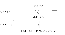
Fig. 4 illustrates according to of the present invention based on the IP protocol stack on the ducted LEP of converging of GE and 10GE, and it is used for layer 3 and transmits grouping;
Fig. 5 illustrates the interchangeable frame form according to the MSR that is used for building ring of one embodiment of the present of invention;
Fig. 6 illustrates the interchangeable frame form according to the CS﹠NM of one embodiment of the present of invention;
Fig. 7 is the expression formula according to TN ID of the present invention and TCCR ID;
Fig. 8 illustrates according to the TDM service channel along MSR of the present invention;
Fig. 9 illustrates according to the TDM service channel on bit FE/GE/10GE of the present invention;
Figure 10 illustrates the expression formula according to 1+1 of the present invention and 1:1 branch protection parameter;
Figure 11 illustrates the expression formula according to 1:N branch protection parameter of the present invention;
Figure 12 illustrates the single fiber ring according to the MSR of an alternative embodiment of the invention;
Figure 13 illustrates the MSR topology of adding, deleting the link type of branch service according to of the present invention;
Figure 14 illustrates the MSR topology that connects according to broadcasting of using for DVB of the present invention;
Figure 15 illustrates the MSR topology according to pseudo-Mesh connection of the present invention;
Figure 16 illustrates according to the physical architecture of the MSR node of one embodiment of the present of invention (being with outer CS﹠NM bus);
Figure 17 illustrates according to the physical architecture of the MSR node of one embodiment of the present of invention (CS﹠NM bus in the band);
Figure 18 illustrates the system equipment layout according to the MSR node of one embodiment of the present of invention.
The specific embodiment
Keyword related to the present invention is as follows: the N-subring structure, converge FE, GE, 10GE; branch road, TDM circuit simulation, protection in the Bandwidth Management, the 50ms of 1+1,1:1 and 1:N; professional multicast, packet-based performance monitoring, monocycle, chain, broadcasting and pseudo-network topology, linear speed filters
1. scope
This patent has proposed to be used for to adopt predistribution and has been connected link tunneling (LEP) mode that connects, that converge the Multiple Service Ring (MSR) of pipeline based on FE/GE/10GE. LEP be provided to be used in particular for the individual unidirectional subring of shown in Figure 1 comprising (N-M) and M (N of unidirectional counter-rotating subring of 1≤M<N) (and N=1,2,3,4,5 ...) on the ring structure. Suggestion N=4,8,16,32,64,128 ..... Usually, in specific (N-1) subring its packet to the of one-way transmission (N-1) subring, and oppositely transfer control is grouped in the N subring. Similarly, specific its packet of N subring one-way transmission is in the N subring, and oppositely (if N is even number) or in the same way (if N is odd number) transfer control grouping in the FWR. Similarly, in the situation of the optical fiber facility fault of (N-1) subring or Signal Degrade, also can be by the default guard channel that is made as (N-1) subring as the N subring of the control channel of (N-1) subring. If optical fiber facility fault or Signal Degrade are provided with in node in the situation of the protection path from a subring to another counter-rotating subring, then the branch service on the N ring structure is protected in 50ms each other automatically. On framework, also support monocycle, chain, broadcasting and pseudo-network topology. The professional tributary interface of MSR node is defined as supporting the TDM circuit simulation. LEP supports the 50ms protection based on 1+1, the 1:1 of branch road and 1:N, the branch road linear speed that limit bandwidth, the branch road of multicast, symmetry and asymmetrical branch road based on branch road merge, divide into groups to filter; the branch road performance monitoring of branch road mirror image, 15 minutes and 24 hours, also be defined simultaneously to support with more complicated route data system in function class like transmit MSR data link frame function (equally as branch road). X.85/Y.1321 and X.86/Y.1323 MSR-LEP provides packet-based transport model for multi-service and many topologys, to inherit and to have expanded the ITU-T suggestion.
This patent is used for Metropolitan Area Network (MAN), is absorbed in hub, enterprise and campus network and other dedicated network of telecommunications and data communication. Network of relation can be also can be not and CWDM (CWDM) or dense wave division multipurpose (DWDM) equipment interface.
2. list of references
Following ITU-T suggestion and other lists of references comprise the clause that becomes clause of the present invention by quoting of this paper. When announcing, indicated version is effective. All lists of references submit to revised edition: therefore, encourage all users of this patent to study as far as possible the latest edition of these lists of references that use lists below.
2.1 ITU-T suggestion
[1] ITU-T Recommendat ion X.85/Y.1321, IP over SDH using LAPS (X.85/Y.1321 ITU-T advise, uses the IP on SDH of LAPS)
[2] ITU-T Recommendation X.86/Y.1323, Ethernet over LAPS (X.86/Y.1323 ITU-T advises, the Ethernet on LAPS)
[3] ITU-T Recommendation X.211 (1995) | ISO/IEC 10022 (1996), Information technology-Open Systems Interconnection-Physical service definition. (the ITU-T suggestion is (1995) X.211 | and ISO/IEC 10022 (1996), and information technology-open system interconnects-the physical traffic definition)
[4] ITU-T Recommendation X.212 (1995) | ISO/IEC 8886 (1996), Information technology-Open Systems Interconnection-Data link service definition (the ITU-T suggestion is (1995) X.212 | and ISO/IEC 8886 (1996), and information technology-open system interconnects-the data link traffic definition)
[5] ITU-T Recommendation X.200 (1994) | ISO/IEC 7498-1 (1994), Information technology-Open System Interconnection-Basic reference model:The basic model (the ITU-T suggestion is (1994) X.200 | and ISO/IEC 7498-1 (1994), information technology-open system interconnects-Basic Reference Model: basic model).
[6] ITU-T Recommendation I.363.1 (1996), (the ITU-T suggestion is (1996) I.363.1, B-ISDN ATM adaptation layer standard: Class1 AAL) for B-ISDN ATM Adaptation Layer specification:Type 1 AAL
2.1 ieee specification
[7] IEEE 802.3 CSMA/CD Access Method and Physical Layer Specifications, 2002 Edition (IEEE 802.3 CSMA/CD access method and physical layer specifications, 2002 editions)
3. definition
This patent has adopted to give a definition:
3.1 converge pipeline (Aggregate Pipe), the physical connection between two adjacent nodes. Converging pipeline is the FE/GE/10GE passage. Suggestion is used along the same bandwidth that converges pipeline of the different spans (span) of same ring. Converging pipeline can be 10/100Mb/s self adaptation (auto-sense) Ethernet, Fast Ethernet, gigabit Ethernet (Gibabit Ethernet), 10 gigabit Ethernets (10GBASE-R, 10GBASE-W, 10GBASE-X)
3.2 control signal frame (Control Signalling Frame), a kind of frame for connecting foundation, Topology Discovery and carry out craft and mandatory protection switching etc. at layer 2 at the branch road of node.
3.3 CT_Request frame (CT_Request Frame, CT claim frame) is used for along the frame of MSR ring transmission allocation list request from node A to Node B.
3.4 CT_Response frame (CT_Response Frame, CT response frame) is used for sending the frame that allocation list responds from Node B to node A along the MSR ring.
3.5 allocation list (CT) (Configuration Table) at engineering operation or during the installation of project stage, is reflected in the mapping table of TCCR between the actual value of TT and TN in the node on the MSR ring and node.
3.6 allocation list is inquired (CTI) (Configuration Table Inquiry), obtains the function of allocation list from node. At engineering operation or during the installation of project stage, will be with having reflected that the CT_Request frame in the CTI parameter of the change part of the TCCR of MSR node on the ring gives other node (one of them be called as Node B) by clean culture/multicast/broadcast mode from a node (being called node A, generally for example is central station) by network management interface. Receive response that all nodes with CTI parameters C T_Request frame will provide a point-to-point by the CT_Response frame with the CTI parameter to node A, described CT_Response frame with the CTI parameter is reflected in the actual disposition expression condition of the local node on the MSR ring.
3.7 config update table (CUT) (Configuration Updating Table), at engineering operation or during the installation of project stage, be reflected in TT and the usable levels modification of TN and the mapping table of internodal TCCR in the node on the MSR ring. Incorrect ICT will cause the fault of the branch road on the MSR ring. At engineering operation or during the installation of project stage, send to other node by broadcast mode from a node (for example normally central site) by network management interface with the CT_Request frame of the CUT parameter of the changing unit that has reflected all node TCCR on the MSR ring. All nodes of receiving the CT_Request frame will construct corresponding TCCR mapping relations in local node, and the response of a point-to-point is provided to the node that sends the CT_Request frame by the CT_Response frame. After receiving the CT-Response frame, the node that the CT_Request frame is sent out in the source sends a CT_Confirm frame (CT acknowledgement frame) to the distant-end node that sends the CT_Response frame.
3.8 the first building ring (FWR) (First Working Ring), N (N=1,2,3,4,5 ...) first outer shroud of ring structure. Usually, it is ring, and sends in one direction data and control packet. When NWR optical fiber facility or node broke down, if be provided with guard channel from a ring to other counter-rotating subrings in node, then the branch service on the N ring structure was automatically protected each other in 50ms.
3.9 force handoff (Forced Switch), by network management or software debugging aids, the operator carries out layer 2 protection in the target span and switches (L2PS). The operator precedence level is higher than manual switching.
3.10 the first building ring disconnected fine (FWR-Fiber-Cut), the parameter of L2PS_Request frame (L2PS claim frame) is used for the state indication that the upper single fiber of expression FWR disconnects.
3.11 initial configuration table (ICT) (Initial Configuration Table), at engineering operation or during the installation of project stage, be reflected in MSR and encircle TT initial and available in the node and the mapping table of TN value and internodal TCCR. At the MSR engineering operation or before the installation of project stage, ICT must be installed in advance. Incorrect ICT will cause the branch service fault on the MSR ring. At initial engineering operation or during the installation of project stage, send to other node by broadcast mode from a node (for example normally station) by network management interface with the CT_Request claim frame of the ICT parameter that is reflected in initial TCCR on the MSR ring. All receive that the node of CT_Request frame will construct the corresponding TCCR mapping relations of local node, and the response of a point-to-point is provided to the node that sends the CT_Request frame by the CT_Response frame. After receiving the CT-Response frame, the node of the CT_Request frame that starts sends a CT_Confirm frame to the distant-end node that sends the CT_Response frame.
3.12 (L2PS) (L2 Protection Switchin) switched in layer 2 protection, a kind of powerful self-healing feature is so that can recover optical fiber facility or node failure in 50ms. Be similar to the K1/K2 protocol that the SONET/SDH ring adopts. L2PS entity detection Link State in the node. If in 20ms (its value is able to programme), both do not received at receive direction that the interFrameGap of MAC do not receive mac frame yet by a node from converging pipeline, if perhaps optical fiber facility or node break down (for example PSD or PSF), then two nodes on the fault span will enter the L2PS state. This function only is used for the situation of MSR ring (dicyclo).
3.13 layer 3 is transmitted grouping (Layer 3 Forwarding Packet), is used for the grouping of forwarding data grouping in node. This grouping is different from those groupings that arrive branch road in the node, also is different from management frame and control signal frame. In logic, node can be used as router and equally treats, and carries out layer 3 and transmits, and transmit grouping from described node to other node forwarding layer 3 according to the Ipv4/6 routing table in the node and Routing Protocol this moment on the MSR ring.
3.14 L2PS_Request frame (L2PS_Request Frame), adjacent two nodes (Node B and node C) from node A to the target span or adjacent two nodes (Node B and node C) of malfunctioning node send the frame of manual switching and force handoff request.
3.15 L2PS state (L2PS State), if node had not both been received the interFrameGap of MAC and had not been received mac frame yet from converging pipeline in 20ms (its value is able to programme), if perhaps optical fiber facility or node failure (for example PSD or PSF) then enter the L2PS state at two nodes in the situation that is provided with the L2PS function, on the fault span. When adopting monocycle, chain or broadcast topology, the L2PS function is closed.
When node enters the L2PS state, transmit mean the frame of receiving from node one side will be forwarded to the same side of this node (namely will be forwarded to from the FWR west to the frame of receiving counter-rotating the N subring the west to). This looks the node that is different from normal condition, transmits at that time to mean from the FWR west and will be forwarded to the east orientation of N subring to the frame of receiving.
3.16 manual switch (Manual Switch), the operator operates by network management or software debugging aids; Carrying out layer 2 protection in the target span switches.
3.17 Multiple Service Ring (MSR) (Multiple Services Ring), Fig. 1 show the MSR topology according to one embodiment of the present of invention.
Shown in Figure 1 be comprise (N-M) individual unidirectional subring and M (N of unidirectional counter-rotating subring of 1≤M<N) (and N=1,2,3,4,5 ...) ring structure. Usually, its packet of specific (N-1) subring one-way transmission, and oppositely transfer control grouping in the N subring. If optical fiber facility fault or Signal Degrade then are provided with in node in the situation of the guard channel from a ring to another counter-rotating subring, the branch service on the N ring structure is protected in 50ms each other automatically. On framework, also support single fiber ring, chain, broadcasting and pseudo-network topology. Each node can up/down one or more branch road independently. MSR supports that multinode sends and traffic engineering simultaneously. Be set at a ring in the situation of backup ring of any other single ring; the protected business of in service aisle other works and less than in the packet loss and traffic lost in the MSR ring, can insert online or delete a node from the MSR ring.
3.18 MSR broadcasts (MSR Broadcast), the frame that sends from a node along the MSR ring can be sent to all other nodes along MSR.
3.19 MSR filter element (MSR Filter Unit) is for filtration and the audit function unit of node address (NA) and TTL. All arrive the frame of MSR filter element and are at first delivered in the buffer of node. The MSR back end will check TTL and the node address of frame, and adopt local NA operation xor function. If TTL is zero, then abandon this frame. If joint NA coupling arrives these frames of destination and no longer is forwarded to neighbours' (only multicast or broadcast frame) along same monocycle. Otherwise those unmatched frames directly arrive neighbours by scheduling unit after the TTL field subtracts 1, and need not anyly process.
3.20 MSR multicast (MSR Multicast) utilizes the MSR-LEP agreement to send to several different nodes along a building ring from the frame of a node.
3.21 MSR back end (MSR Data Node), it is such network node, it have east orientation Rx, east orientation Tx along MSR ring, west to Rx be connected the separate branches that converges pipeline connection and one or more up/down to Tx. It also has reception, sends and transmit the function of management frame, control signal and Frame in a node. Different connection configurations are applied to different topologys.
3.22 the MSR-LEP agreement at MAC/TCE (or PPP/Ipv4/Ipv6) frame (or bag) with converge data link layer protocol between the Physical layer of pipeline, is used for communicating between the different nodes on the MSR. MSR-LEP comes work by the network management/signaling frame that sends Frame and be associated in single ring.
3.23 MSR-LEP Rx processor (MSR-LEP Rx Processor) is used for one group of function in the MSR-LEP of Rx direction protocol processes. It comprises the Rx filter element, the MSR-LEP protocol processes that multicast/broadcast is distinguished, TT/TN value and other are relevant.
3.24 MSR-LEP sending processor (MSR-LEP Tx Processor) is used for one group of function in the MSR-LEP of sending direction protocol processes. It comprises the Tx scheduling unit, determine NA, the function of TTL, TT, TN, FCS, multicast/broadcast. In other relevant MSR-LEP protocol processes is also included within.
3.25 MSR scheduling unit (MSR Schedule Unit) is according to from the multicast/broadcast frame of the priority of the transmitted frame of upstream node, site-local with send frame realizes being sent out the control function of frame in node unit. If have several frames to be sent out in node simultaneously, then scheduling unit will be checked the priority of frame, and determine which frame at first is sent to the downstream along ring.
3.26 N_ct is used for the retransmission count that allocation list operates. All nodes on ring are configured ICT in the engineering opening stage with wait. After sending the CT_Request frame, if node A does not receive corresponding CT_Response frame, then node A will send the CT_Request frame automatically again behind retransmission timer Timer_ct (able to programme). Retransmit (N_ct is also able to programme) afterwards at N time, just think that Node B is inaccessible. N_ct is also used by the CUT operation.
3.27 management frame (Network Management Frame) is used for the frame of performance and malfunction monitoring, node configuration management etc. in MSR ring or other topology.
3.28 node address (NA) (Node Address), the address of MSR node on the ring link. NA is local address, and just has local significance at MSR ring or other different topologys. It comprises 4 eight hytes. Each bit (binary zero or " 1 ") is corresponding to a node of any single ring. For example, binary number " 00,100,000 00,000,000 00,000,000 00000000 " represents the 3rd address of node (website); Binary number " 00,000,100 00,000,000 00,000,000 00000000 " represents the 6th address of node (website) (referring to Fig. 1). Because the online insertion of MSR support node, therefore also can use new the 7th address of node of inserting of binary number " 00,000,010 00,000,000 00,000,000 00000000 " representative, and the actual numbered positions of the 7th node can be corresponding to the centre position between website shown in Figure 11 and website 2. The snap left of all node address, and before operation, installed in advance by (NVRAM). Maximum node numbering on the MSR ring is 32 (for the needs of realizing, people can adopt ethernet mac and Ipv4 address to carry out external network management).
3.29 normal condition (Normal State) is described MSR and is had the node of normal transmission-receiving function on the ring and be not operated in state in the L2PS state. In normal condition, forwarding means that the frame that receives from the upstream will be forwarded to the downstream. This state only is used for the MSR ring.
3.30 N building ring (NWR) (N-th Working Ring), N (N=1,2,3,4,5 ...) a ring in the ring structure. Usually, it is a ring or counter-rotating subring, and sends data and control packet in same direction. In the situation of the facility of (N-1) subring or node failure, if be provided with guard channel from a ring to another counter-rotating subring at node, then the branch service on the N ring structure is protected in 50ms each other automatically.
3.31 N ring structure (N-ring Structure), N (N=1,2,3,4,5 ...) ring structure comprise unidirectional (N-M) individual subring and M (1≤M<N) individual unidirectional counter-rotating subring, as shown in Figure 1. The value of N and M depends on the demand of application, the distribution of ability and the strategy of protection. It can be configured to 1:N or M:N. Select ground, some ring uses GE, other use 10GE. Usually, specific (N-1) subring one-way transmission packet, and oppositely transfer control grouping in the N subring. Similarly, its packet of therein one-way transmission of specific N subring, and in oppositely (if N is even number) or in the same way (if N is odd number) transfer control grouping in the FWR. Similarly, in optical fiber facility fault or (N-1) in the situation of the Signal Degrade of subring, also can the default guard channel that is made as (N-1) subring as the N subring of the control channel of (N-1) subring. If optical fiber facility fault or Signal Degrade then are provided with in node in the situation of the guard channel from a ring to another counter-rotating subring, the branch service on the N ring structure is protected in 50ms each other automatically.
3.32 NWR disconnected fine (NWR-Fibre-Cut), a parameter of L2PS_Request frame is used to indicate the state indication that the single fiber on NWR disconnects.
3.33 physical signalling deteriorated (PSD) (Physical Signal Degrade), at random or automatically, caused by physical signalling deteriorated (for example excessive piece or bit error rate (BER)). In case it occurs, L2PS comes into force the fault span on the MSR ring.
3.34 physical signalling fault (PSF) (Physical Signal Failure), at random or automatically, cause (for example optical fiber facility fault) by the physical signalling fault. In case it occurs, L2PS comes into force the fault span on the MSR ring.
3.35 reference point G1 (Reference Point G1), the reference point between RX deframer and Rx filter. The processing place of the 10GMAC/GMAC Physical layer of its representative before converging XGMII/GMII/MII.
3.36 reference point G2 (Reference Point G2), the reference point between TX framer and Tx scheduler. The process source of the 10GMAC/GMAC Physical layer of its representative before converging XGMII/GMII/MII.
3.37 reference point T1 (Reference Point T1), the reference point between branch road RX deframer and MSR-LEP processor. The MSR-LEP of its representative before the encapsulation of the physics branch roads such as TCE processes the place.
3.38 reference point T2 (Reference Point T2), the reference point between branch road TX framer and MSR-LEP processor. The MSR-LEP process source of its representative before the physics branch roads such as TCE are removed.
3.39 RX deframer (Rx Framer), the Rx side converge the abstract of pipeline physics deframer, it represents the deframer of FE/GE/10GE. Be gigabit Ethernet if converge pipeline, then related rate and the signal at reference point G1 is GMII.
3.40 Timer_ct is used for the timer of the re-transmission of allocation list operation. All nodes on the ring are configured ICT in engineering opening or during the installation of project stage with wait. After sending the CT_Request frame, if node A does not receive corresponding CT_Response frame, then node A will send the CT_Request frame automatically again behind retransmission timer Timer_ct (able to programme). Think that Node B is inaccessible through N_ct re-transmission (N_ct is also able to programme) afterwards. N_ct is also used by the CUT operation.
3.41 Timer_WTR, for the timer that prevents the L2PS vibration, before MSR returned normal condition, L2PS can wait for the Timer_WTR period (its value is programmable). Only when being set, the L2PS function uses this timer.
3.42 branch road (Tributary), from/go to the independent up/down branch road of MSR back end on FE/GE/10GE (after the packetizing) (or professional) channel, similar a series of " from special line for rental or the special circuits of operator ". Branch road can be multi-service. Different branch roads can designated different priority.
3.43 branch road adaptation function (Tributary Adaptation Function Unit), from/go to the adaption function of various separate branches type signals, various separate branches type signals from/go to reference point T1 T2. It has branch road adaptive source function and the adaptive Su Gongneng of branch road. The place is corresponding to reference point T1, and the source is corresponding to reference point T2. This adaption function comprises signal and rate transition and the synchronizing function between both sides.
3.44 branch road interconnection relation (TCCR) (Tributary Cross-connection Relationship), the table of the branch road interconnection relation of all nodes on reflection MSR ring or other topologys. It is MSR or other topological global table, i.e. the global table of the source of all effective branch roads and place relation.
3.45 branch road Rx deframer (Tributary Rx Framer), abstract at the branch road physics deframer of Rx end, it represents the TCE deframer. If branch road for example is TCE, then the data at reference point T1 are payloads of TCE frame.
3.46 branch road TX framer (Tributary Tx Framer), abstract at the branch road physics framer of sending side. It represents the TCE framer.
3.47 branch road number (TN) (Tributary Number), the numbering of the same type tributary port on a node. If the 7th ISDN is provided in node, then this numbering is 7.
3.48 branch type (TT) (Tributary Type), go to/from the type of a path channels of the independent up/down of MSR back end. This can be that TCE is professional.
3.49 Topology Discovery (opology Discovery), data link control function in MSR-LEP, be used for finding which is its neighbours and how many nodes is arranged work (must receive the transmission frame to guarantee same station, and the destination address of frame pointing to itself) at MSR ring. To Topology Discovery (Topology Discovery) frame is added its node address according to the order of sequence as parameter in each station, the length of undated parameter, and this frame passed to neighbours along the MSR shown in the table 6 ring. Do not need to know the mapping relations between node address and the physical location. Each node periodically carries out topology discovery function by send the Topology Discovery frame at the first or second building ring (value of timer is able to programme). Topology Discovery adopts a kind of signaling format.
3.50 the existence time limit (Time to Live), this 6 bit field is hop count, and every minor node is transmitted a frame, and this 6 bit field will subtract one. The maximum quantity of the node in the ring of the MSR described in the described patent is 32. In the L2PS situation, the node on the ring sum can be 64.
3.51 send framer (Tx Framer), converge physics framer abstract of pipeline in the sending side, it represents the framer of FE/GE/10GE.
3.52 Wait-to-Restore (WTR) (Wait to Restore), at random or automatically, in case PSF, PSD or fiber plant fault disappear, when the node that enters L2PS satisfies the standard of recovering by automatic activation. For preventing the L2PS vibration, L2PS can wait for the Timer_WTR cycle (its value is able to programme) before MSR enters normal condition. This function only is used for the situation of MSR ring (dicyclo).
3.53 WTR_Request frame (WTR_Request Frame) is used on the fault span peer node by the frame of L2PS state transitions to normal condition. In case PSF, PSD or fiber plant fault disappear, after the satisfied standard of recovering of the node that enters the L2PS state, be activated. Be the anti-normal condition that enters. This function only is used for the situation of MSR ring (dicyclo).
4. abbreviation
4.1 the abbreviation of in IEEE 802.3, describing
This patent is used the following abbreviation of describing in IEEE 802.3
1) 10GE 10 gigabit Ethernets
2) FE Fast Ethernet comprises the automatic sensing-detecting Ethernet of 10/100Mb/s
3) GE gigabit Ethernet
4) LAN LAN
5) MAC media interviews control
6) MII GMII
7) GMII gigabit GMII
8) XGMII10 gigabit GMII
4.2 the abbreviation of describing I.321 and I.361 at ITU-T
This patent is used the following abbreviation of describing in the ITU-T suggestion
A) ATM Asynchronous Transfer Mode (Asynchronous Transfer Mode)
4.3 the abbreviation of in ETSI, describing
This patent is used the following abbreviation of recommending regulation among the EN 300 429 at ETSI:
A) DVB DVB
4.4 the abbreviation of in this patent, describing
1) FWR the first building ring
2) CS﹠NM control signal and network management
3) CT allocation list
4) CTI allocation list inquiry
5) CUT config update table
6) the thick wavelength of CWDM divides multiplexing
7) DL data link
8) the intensive wavelength of DWDM divides multiplexing
9) ICT initial configuration table
10) 2 protection of L2PS layer are switched
11) LSFFU linear speed filtering function
12) MAC media Access Control
13) layer-management of MDL data link
14) MSR Multiple Service Ring
15) MSR LEP Multiple Service Ring-link tunneling
16) N building ring of NWR
17) (N-1) WR N-1 building ring
18) (N-2) WR N-2 building ring
19) PDU protocol Data Unit
20) the PSD physical signalling is deteriorated
21) PSF physical signalling fault
22) NA node address
23) Rx receive data
24) SDU Service Data Unit
25) ST source branch road
26) TBM is based on the multicast of branch road
27) TBP is based on the protection of branch road
28) TCCR branch road interconnection relation
29) TCE TDM circuit simulation
30) TDM time division multiplex
31) TMG branch road merging group
32) TTBP is based on the protection of TCE branch road
33) TN branch number
34) TT branch type
35) Tx sends data
36) WTR Wait-to-Restore
5 MSR network frames
5.1 the element of ring
MSR N shown in Figure 1, as to comprise (N-M) individual unidirectional subring and M unidirectional counter-rotating subring (N=1,2,3,4,5 ...) ring structure. Usually, specific (N-1) subring one-way transmission packet, and oppositely transfer control grouping in the N subring. In the situation of optical fiber facility fault or Signal Degrade, the node that has then received the loss of signal or Signal Degrade will notify the peer node on the fault span that data and the control packet of correspondence switched to another counter-rotating subring. Do not use in this case around function (wrapping function) on framework, support single fiber ring, chain, broadcasting and pseudo-network topology yet. Each node can up/down one or more (for example be used for the forwarding data grouping, the DVB port also can transmit and receiving layer 3 (Ipv4/Ipv6 grouping) forwarding data grouping (also being branch road)), the independently branch road of control signal frame and management frame. MSR supports multicast and broadcasting and the forwarding data grouping of these branch services. Converging pipeline can be FE/GE/10GE. In situation about being provided with as the ring of the backup of other rings, can will normally operate other protected business along the MSR ring simultaneously from encircling online insertion and deletion of node, and bag loss and traffic lost.
5.2 the multi-service in the frame type on the ring and the branch road
Each node has the ability of up/down such as the defined some separate branches business of table 1.
Multi-service type in the table 1-branch road
| Branch type | Ability | ||
| TCEs | The full duplex point-to-point | Multicast | Broadcasting |
| Annotate 1: the bandwidth that converges pipeline depends on the professional demand of disposing. In the situation of needs, the bandwidth that converges branch road is half of bandwidth that converges pipeline, so that the protection bandwidth to be provided. In the situation that service needed allows, converging the branch road bandwidth can be above converging bandwidth. Annotate 2: multicast is based on the point-to-multipoint transmission of half-duplex of node, and broadcasting is based on the half-duplex point of node to upper other transmission of having a few of ring. | |||
On the ring there be the frame of transmitting-receiving: the multi-service frame of standing one by one in (1) in table 2, (2) layer 3 (Ipv4/Ipv6 bag) forwarding data frame (similar router), (3) control signal frame and (4) management frame are used for illustrating along the all-round power of point-to-point, multicast and the broadcasting of a ring.
Table 2-frame type
| Frame type | Ability | ||
| The multi-service frame of standing one by one | Point-to-point | Multicast | Broadcasting |
| Layer 3 (Ipv4/Ipv6 bag) forwarding data divide into groups (the similar router of node and operate) | Point-to-point | Multicast | Broadcasting |
| The control signal frame | Point-to-point | Multicast | Broadcasting |
| Management frame | Point-to-point | Multicast | Broadcasting |
Fig. 2 shows according to the Tx of the MSR back end of one embodiment of the present of invention and Rx functional diagram
5.3 the part of back end
The MSR back end is as a system equipment, and it has east orientation Rx, east orientation Tx, west and converges pipeline and one or more up and down separate branches to Rx and west to Tx. The MSR back end also has reception, sends and transmit the function of management frame, control signal and Frame in node. When different connection configuration is applied to differently when topological, should make corresponding changes. The element of MSR back end is as described below:
5.3.1 converge pipeline: the physical connection between two adjacent nodes. Converge the passage that pipeline is FE/GE/10GE. Suggestion is used the identical pipeline bandwidth that converges along the different spans (span) of same ring.
5.3.2 branch road: from/go to the bypass passage of the independent up/down of MSR back end, just as a series of " special line for rental or the special circuits of operator ". Branch road can be port G.702. Different branch roads can designated different priority.
5.3.3 the first building ring (FWR): N (N=1,2,3,4,5 ...) first outer shroud of ring structure. Usually, it is subring, and transmits in the same way data and control packet. When NWR optical fiber facility or node failure, if be provided with in the node from a subring to other the counter-rotating subrings protection channel, then the branch service on the N ring structure is automatically protected each other in 50ms.
5.3.4 N building ring (NWR): N (N=1,2,3,4,5 ...) single ring in the ring structure. Usually, it is subring or counter-rotating subring, and sends data and control packet in same direction. In the situation of the facility of (N-1) subring or node failure, if be provided with guard channel from a subring to other counter-rotating subrings at node, then the branch service on the N ring structure is protected in 50ms each other automatically.
5.3.5 N ring structure: comprise unidirectional (N-M) individual unidirectional subring and M (N of the individual unidirectional counter-rotating subring of 1≤M<N) (and N=1,2,3,4,5 ...) ring structure, as shown in Figure 1. The value of N and M depends on the demand of application, distribution and the protection strategy of capacity. Can be configured to 1:N or M:(N-M (M≤N-M)). Select ground, GE is used in some subrings, and other use 10GE. Usually, specific (N-1) subring its packet to the of one-way transmission (N-1) subring, and oppositely transfer control is grouped in the N subring. Similarly, specific N subring with its packet one-way transmission to the N subring, and in oppositely (if N is even number) or in the same way (if N is odd number) transfer control grouping in the FWR. Similarly, in the situation of the optical fiber facility fault of (N-1) subring or Signal Degrade, also can the default protection channel that is made as (N-1) subring as the N subring of the control channel of (N-1) subring. If optical fiber facility fault or Signal Degrade then are provided with in node in the situation of the guard channel from a subring to other counter-rotating subring, the branch service on the N ring structure is protected in 50ms each other automatically.
5.3.6 MSR filter element: for filtration and the audit function unit of NA and the TTL of frame. All arrive the frame of MSR filter element and are at first delivered in the buffer memory of node. The MSR back end will check TTL and the node address of frame, and local NA is carried out XOR (XOR) operation. If TTL is zero, then abandon this frame. If the NA coupling, these frames that then arrive the destination are not forwarded to neighbours' (only multicast or broadcast frame) along same ring. Otherwise those unmatched frames are not directly done any processing to neighbours by scheduling unit after TTL subtracts 1.
5.3.7 MSR scheduling unit: according to from priority, the multicast/broadcast frame of the transmitted frame of upstream stations with send frame and from the control function that in node, sends frame of the transmission frame of site-local. If will send several frames at one time in node, then scheduling unit will determine which frame at first is sent to the downstream along ring.
5.3.8 RX deframer: Rx end converge the abstract of pipeline physics deframer, it represents the deframer of GE/10GE.
5.3.9 TX framer: abstract at the physics framer that converges pipeline of Tx side, it represents the framer of GE/10GE.
5.3.10 branch road Rx deframer: abstract at the branch road physics deframer of Rx end. It represents the ISDN deframer.
5.3.11 branch road TX framer: abstract at the physics framer of the branch road of Tx side. It represents the ISDN framer.
5.4 the reference point in the back end
Four different reference points in node, have been defined.
5.4.1 reference point G1: the reference point between RX deframer and Rx filter. The processing place of the 10GMAC/GMAC Physical layer of its representative before converging XGMII/GMII/MII.
5.4.2 reference point G2: the reference point between TX framer and Tx scheduler. The process source of the 10GMAC/GMAC Physical layer of its representative before converging XGMII/GMII/MII.
5.4.3 reference point T1: the reference point between branch road RX deframer and MSR-LEP processor. The processing place of the MSR-LEP of its representative before the encapsulation of the physics branch roads such as TCE.
5.4.4 reference point T2: the reference point between branch road TX framer and MSR-LEP processor. The MSR-LEP process source of its representative before the peeling off of the physics branch roads such as TCE.
5.5 the data flow towards Rx and the Tx of branch road
Usually, its packet of specific (N-1) subring one-way transmission, and oppositely transfer control grouping in the N subring. Similarly, its packet of therein one-way transmission of specific N subring, and in oppositely (if N is even number) or in the same way (if N is odd number) transfer control grouping in (N-1) WR. Similarly, in the situation of the optical fiber facility fault of (N-1) subring or Signal Degrade, also can be by the default guard channel that is made as (N-1) subring as the N subring of the control channel of (N-1) subring.
5.5.1 Rx direction
Enter reference point G1 node the Rx frame and carry out the RX deframer after be sent to the Rx filter element. The Rx filter element will be checked TTL, FCS and the NA with filtering frames. All arrive the frame of MSR filter element and are at first delivered in the buffer memory of node. The MSR filter element will check TTL, FCS and the NA of frame, and local NA is carried out the XOR computing. If TTL is zero or fcs error, then take out and abandon this frame.
If the NA coupling, these frames not on same ring (for example (N-1) WR) that arrive the destination are sent to neighbours. Otherwise those unmatched frames directly arrive neighbours by scheduling unit after ttl field subtracts 1, and without any need for processing.
If the frame of receiving is multicast or broadcast frame, it at first is sent to the Tx scheduling unit, is sent to downstream node after ttl field subtracts one; It is copied into the processing of another buffer memory further to be correlated with in local node simultaneously.
After having checked TTL, NA and multicast/broadcast, the frame that arrives the destination carries out the second program in local node (station). Be whether TT and TN be illegal. If illegal, this frame will be dropped. If legal, will at reference point T1 corresponding tributary port, layer 3 retransmission unit, control signal unit or network management unit be arrived in this frame transfer according to its TT and TN value.
5.5.2 Tx direction
The Rx frame that enters the Tx processor from tributary port, layer 3 retransmission unit, control signal unit or the network management unit that is positioned at reference point T2 obtains TTL, FCS, TT, TN value and multicast/broadcast requirement, and then type and port arrangement, layer 3 forwarding grouping, the needs of control signal or the needs of network management according to branch road obtain node address. Next, these frames are sent to the Tx scheduling unit. One has 3 kinds of inputs: from the multicast/broadcast frame of other node upstream, be used for the point-to-point frame that transmits from the upstream and the frame that sends from site-local. They all will enter the Tx scheduling unit. Scheduling unit operates in the control function of these transmission frames in the node according to the priority of these frames. If there are some frames to be sent out simultaneously in node, then scheduling unit will determine which frame will at first go to the downstream along ring. During the Tx burst period, also may abandon the frame of low priority.
5.6 layer 3 is transmitted the operation of grouping
The MSR back end can transmit the relevant frame of IP to other node according to the relation between Ipv4/Ipv6 routing table and its NA/TT/TN on the MSR ring as router, and this node can provide the tributary port for rental of picture special circuit or circuit simultaneously. When MSR back end during as router, the control plane of router (MSR back end) (for example operation of Routing Protocol), network management plane (for example Simple Network Management Protocol) and datum plane will be shared the same logical channel corresponding to the value of NA, TT and TN along described ring. That is, the control signal frame of router (MSR back end) will be operated in the passage different from the control signal frame of MSR ring itself.
5.7 the operation of control signal frame
5.7.1 the operation of Topology Discovery frame
5.7.1.1 the operation of the Topology Discovery frame under normal condition
As a kind of control frame among the MSR-LEP, the Topology Discovery frame is used for finding which is its neighbours and how many nodes is arranged in work (to guarantee and must receive the transmission frame by the same website that sends the Topology Discovery frame that the destination address of frame points to itself) at the MSR ring. The Topology_Discovery_Request frame with sky parameter is periodically broadcasted along all rings respectively in each station (for example node A) (Timer_topology_discovery defaults to 3 seconds, and is able to programme). (for example node A) provides and replys the Topology_Discovery_Response frame of all stations (for example Node B) of receiving the Topology_Discovery_Request frame by comprising our station node address (for example node address of Node B) to that station. After obtaining the Topology_Discovery_Response frame, node A adds the node address received and ttl value in its topological address storehouse in node A to by the order of website. The difference that depends on ttl value along the order of ring. The state of ttl value, Node B (normal condition or L2PS state), ring status (normal condition or L2PS state) and (N-1) address of the value of WR/NWR and Node B be bound to together the NA of Node B as a record in the topological address storehouse of node A. The minimum and maximum value of TTL in the record of (N-1) WR/NWR is corresponding to two of node A adjacent neighbours. (N-1) record in the topological address storehouse of WR/NWR is independent operated.
If obtain same result behind continuous 3 transmission Topology Discovery frames, then the operation of Topology Discovery frame is effective, and refreshes the topological state in node. Otherwise the previous record of topological state will remain unchanged. (N-1) WR in node and operation and the record of NWR Topology Discovery are performed independently.
5.7.1.2 the operation of the Topology Discovery frame in the situation of the disconnected fibre of (N-1) WR
MSR-LEP comes work by following manner: be sent in the Frame among (N-1) WR and network management/control frame of being associated, and also be sent in NWR and (N-2) Frame among the WR and the network management/control frame that is associated.
If for example 1 the upper single fiber of (N-1) WR has broken or PSF occurred from node 2 to node in Fig. 1, then node 1 detects PSF at (N-1) WR. Node 1 and node 2 (N-1) WR upper from node 2 to node 1 and node 2 enter the L2PS state, and the broadcasting of all websites among Xiang Zaihuan L2PS_Event_Report frames. At this moment, the Frame on NWR is maintained at normal condition with corresponding network management/control frame and node 3,4,5 with 6 as usually. The Topology_Discovery_Request frame with sky parameter is at first periodically broadcasted along (N-1) WR in node 1,2,3,4, any one station (for example node C) of 5 and 6 (the Timer_topology_discovery default value is 3 seconds, and is able to programme). If when having arrived node 1 or 2 or be sent to node 2 from node 1 with this frame, then the route of this Topology_Discovery_Request frame will forward on the reverse NWR. If node 2 and node 1 along (N-1) WR are in the L2PS state, then these frames on the NWR and the ttl value of node that is not in the L2PS state are when will doubling than the value under the normal condition when these nodes send a frame. All receive that the website (for example node D) of Topology_Discovery_Request frame sends response to that website (for example node C) by the Topology_Discovery_Response frame with local node address (for example node address of node D). Node C adds the node address received and ttl value in node C its topological address storehouse by the order of website. The state of ttl value, node D (normal condition or L2PS state), ring status (normal condition or L2PS state) and (N-1) address binding of the value of WR/NWR and node D be used as a record in the topological address storehouse in node C together. The minimum and maximum value of TTL in the record of (N-1) WR/NWR is corresponding to two neighbours of node C. (N-1) record in the topological address storehouse of WR/NWR is separate operation.
5.7.1.3 the operation of the Topology Discovery frame in the situation of the disconnected fibre of NWR
If for example in Fig. 1 on 2 the NWR from node 1 to node single fiber broken or PSF occurred, then node 2 detects PSF at NWR. Node 2 and node 12 enter the L2PS state from node 1 to node on NWR, and to the L2PS_Event_Report frame of all websites broadcasting on a ring. At this moment, the Frame on NWR and corresponding network management/control frame and node 3,4,5,6 all are maintained at normal condition as usually. The Topology_Discovery_Request frame with sky parameter is at first periodically broadcasted along NWR in any one station in the node 1,2,3,4,5 and 6 (for example node C) (the Timer_topology_discovery default value is 3 seconds, and is able to programme). If be sent to node 1 when having arrived node 1 or 2 with this frame or from node 2 after, the route of this Topology_Discovery_Request frame will forward on reverse (N-1) WR. If the NWR span is in the L2PS state, then at these frames on the NWR and the ttl value of node that is not in the L2PS state when when these nodes send a frame, will doubling than the value under the normal condition. All receive that (for example: node D) the Topology_Discovery_Response frame by comprising local node address (for example NA of node D) provides response to that website (for example node C) for the website of Topology_Discovery_Request frame. Node C adds the node address received and ttl value in its topological address storehouse in node C to by the order of website. Along the order dependent of encircling in the difference of ttl value. The state of ttl value, node D (normal condition or L2PS state), ring status (normal condition or L2PS state) and (N-1) value of WR/NWR and the node address of node D bind together a record that is used as in the topological address storehouse of node C. (N-1) the minimum and maximum ttl value in the record of WR or NWR is corresponding to two neighbours of node C. (N-1) record in the topological address storehouse of WR and NWR is separate operation.
5.7.1.4 the operation of the Topology Discovery frame in the situation of two-way disconnected fibre
If for example in Fig. 1 in that the upper two-way fibre of 2 (N-1) WR and NWR has broken or PSF occurred from node 1 to node, then node 1 and node 2 detect PSF at (N-1) WR and NWR respectively. Node 1 and node 2 are upper from node 1 to node 2 and 1 enter the L2PS state from node 2 to node on NWR at (N-1) WR, and in a ring to L2PS_Event_Report frame of all websites broadcasting. At this moment, node 3,4,5,6 all is maintained at normal condition as usually. Any one station (for example in the node 1,2,3,4,5 and 6, node C) along (N-1) WR and the NWR Topology_Discovery_Request frame of the broadcasting of (the Timer_topology_discovery default value is 3 seconds, and is able to programme) with sky parameter periodically. If when having arrived node 1 or 2 or when being sent to node 2 or being sent to node 1 from node 2 from node 1, this Topology_Discovery_Request frame will be changed to NWR or oppositely be changed to (N-1) WR from NWR from (N-1) WR with this frame. If (N-1) WR and NWR span all are in the L2PS state, at these frames on (N-1) WR and the NWR and the ttl value of node that is not in the L2PS state when when these nodes send a frame, will doubling than the value under the normal condition. All receive that the website (for example node D) of Topology_Discovery_Request frame sends response by the Topology_Discovery_Response frame with local node address (for example NA of node D) to that website (for example node C). Node C adds the node address received and ttl value in its topological address storehouse in node C to by the order of website. Along the order dependent of website of ring in the difference of ttl value. The state of ttl value, node D (normal condition or L2PS state), ring status (normal condition or L2PS state) and (N-1) value of WR/NWR and the address of node D be bundled in together, with as a record in the topological address storehouse of node C. Minimum and maximum ttl value in the record of (N-1) WR or NWR is corresponding to two neighbours of node C. (N-1) record in the topological address storehouse of WR and NWR is independent separate operation.
5.7.1.5 the operation of the Topology Discovery frame in the situation of bi-directional failure occurs in the node both sides
For example, if bi-directional failure all occurs in the both sides of node 2, then node 1 and node 3 are respectively at NWR and (N-1) WR detection PSF. Node 1 and node 3 are upper from node 1 to node 3, on NWR from node 3 to node 1 and enter the L2PS state at (N-1) WR, and in a ring to L2PS_Event_Report frame of all websites broadcasting. At this moment, node 4,5,6 all is maintained at normal condition as usually. The Topology_Discovery_Request frame with sky parameter is periodically broadcasted along (N-1) WR and NWR in any one station in the node 1,3,4,5 and 6 (for example node C) (the Timer_topology_discovery default value is 3 seconds, and is able to programme). If this frame has arrived node 1 or 3 or sent to node 3 from node 1 or sent to node 1 from node 3, the route of this Topology_Discovery_Request frame will be changed to NWR or be changed to (N-1) WR from NWR in the other direction from (N-1) WR. If (N-1) WR and NWR span all are in the L2PS state, then at these frames on (N-1) WR and the NWR and the ttl value of node that is not in the L2PS state when when these nodes send a frame, will doubling than the value under the normal condition. All receive that the website (for example node D) of Topology_Discovery_Request frame sends response by the Topology_Discovery_Response frame with local node address (for example NA of node D) to that website (for example node C). Node C adds the node address received and ttl value in its topological address storehouse in node C to by the order of website. Along the order dependent of website of ring in the difference of ttl value. The state of ttl value, node D (normal condition or L2PS state), ring status (normal condition or L2PS state) and (N-1) value of WR/NWR and the address of node D be bundled in together, with as a record in the topological address storehouse of node C. (N-1) the minimum and maximum TTL value of the record of WR or NWR is corresponding to two neighbours of node C. (N-1) record in the topological address storehouse of WR and NWR is independent operation.
5.7.2 the operation of manual switching and force handoff frame
In initial engineering opening or during the engineering operation stage, with being sent to other node from the network management interface of a node (being called node A, for example central station) with clean culture or multicast mode for the L2PS_Request frame of one or two span (span) Manual_Switch on the MSR ring or Forced_Switch parameter. All receive that the adjacent node (Node B and C) of node (being called as Node B) on target span (span) of L2PS_Request frame carries out corresponding handover operation, by a response of returning a point-to-point with the L2PS_Response frame of the parameter of Successful_Switch or Unsuccessful_Switch to node A, send L2PS_Event_Report frame with the parameter of one group of Forced_Switch/Manual_Switch and L2PS state to specified node (being connected to network management), and/or all websites that are in normal condition among the Xiang Zaihuan send one with the L2PS_Event_Report frame of the parameter of one group of Forced_Switch/Manual_Switch and L2PS-State. If node A receives two correct responses from Node B and node C, then carried out successful operation, otherwise, operation failure.
5.7.3 the operation of the L2PS in PSF/PSD and node failure situation
5.7.3.1 (N-1) the disconnected fine operation of WR
If for example in Fig. 1 in that (N-1) WR upper (N-1) WR fibre of 2 has broken or PSF occurred from node 1 to node, then node 1 detects PSF at (N-1) WR, that is the interFrameGap of, both not received MAC in than (N-1) WR of jitty in 20ms (value of T200 and N200 is able to programme) is not received mac frame yet. To start the L2PS function at the L2PS of node 1 entity, and carry out following subfunction:
(1) node 1 enters the L2PS state, and will issue node 2 along the jitty of NWR with the L2PS_Request frame of (N-1) WR_Fiber_Cut parameter. After receiving this frame, node 2 also enters the L2PS state, issue specified node (in most cases being connected to network management) with the L2PS_Event_Report frame of the parameter of one group of NWR_Fiber_Cut/ (N-1) WR_Fiber_Cut, PSF/PSD and L2PS-State, or be broadcast to all nodes that are in normal condition in ring with the L2PS_Event_Report frame of the parameter of one group of NWR_Fiber_Cut/ (N-1) WR_Fiber_Cut, PSF/PSD and L2PS-State. In the L2PS state, 1 frame all switches on the long-channel of reciprocal NWR from node 2 to node along the upper jitty of (N-1) WR for all.
(2) after the PSF on the node 2 removed, node 1 entered normal condition, and started Timer_WTR (able to programme). In case Timer_WTR is overtime, node 1 sends one with the WTR-Request frame of Successful_WTR parameter to node 2 immediately along described jitty and long-channel. After receiving this frame, node 2 is got back to normal condition from the L2PS state.
5.7.3.2 the disconnected fine operation of NW
If for example in Fig. 1 on 2 the NWR from node 1 to node single fiber broken or PSF occurred, then node 2 detects PSF at NWR. The interFrameGap of namely both not received MAC on the NWR of the inherent jitty of 20ms (its value is able to programme) is not received mac frame yet. The L2PS entity of node 2 will start the L2PS function and carry out following operation:
(1) node 2 enters the L2PS state, and will issue node 1 along the jitty of (N-1) WR with the L2PS_Request frame of NWR_Fiber_Cut parameter. After receiving this frame, node 1 also enters the L2PS state, and send L2PS_Event_Report frame with one group of NWR_Fiber_Cut/ (N-1) WR_Fiber_Cut, PSF/PSD and L2PS-State state parameter to specified node (interconnection network management), and/or all websites broadcasting that are in normal condition among the Xiang Zaihuan are with the L2PS_Event_Report frame of one group of NWR_Fiber_Cut/ (N-1) WR_Fiber_Cut, PSF/PSD and L2PS-State parameter. In the L2PS state, 2 frame all switches on the long-channel of reciprocal (N-1) WR from node 1 to node along the upper jitty of NWR for all.
(2) after the PSF on the node 2 removed, node 2 entered normal condition, started Timer_WTR (able to programme). In case Timer_WTR is overtime, node 2 along the jitty of NWR and (N-1) the long-channel of WR send one with the WTR-Request frame of Successful_WTR parameter to node 1 immediately. After receiving this frame, node 1 is got back to normal condition from the L2PS state.
5.7.3.3 the two-way fine operation that disconnects
If for example in Fig. 1 in that the upper two-way fibre of 2 (N-1) WR and NWR has all broken or PSF occurred from node 1 to node, then node 1/ node 2 detects PSF at NWR/ (N-1) WR, that is, both do not received on (N-1) WR of the inherent jitty of 20ms (its value is able to programme) and NWR that the interFrameGap of MAC do not receive mac frame yet. L2PS entity in node 1 and the node 2 will start the L2PS function and carry out following subfunction:
(1) node 1/ node 2 enters L2PS state itself, and will issue node 2/ node 1 along the long-channel of (N-1) WR/NWR with the L2PS_Request frame of NWR_Fiber_Cut/ (N-1) WR_Fiber_Cut parameter. After receiving this frame, node 2 and node 1 enter the L2PS state, and send L2PS_Event_Report frame with one group of NWR_Fiber_Cut/ (N-1) WR_Fiber_Cut, PSF/PSD and L2PS-State parameter to the specified node of interconnection network management, and/or all websites broadcasting that are in normal condition among the Xiang Zaihuan are with the L2PS_Event_Report frame of one group of NWR_Fiber_Cut/ (N-1) WR_Fiber_Cut, PSF/PSD and L2PS-State parameter. In the L2PS state, all along the upper jitty of (N-1) WR/NWR from node 1 to node 2 or from node 2 to node 1 frame all switches on the long-channel of reverse NWR/ (N-1) WR.
(2) after the PSF on node 1 and the node 2 removed, node 1 and node 2 entered normal condition, started Timer_WTR (able to programme). In case Timer_WTR is overtime, node 1/ node 2 sends one with the WTR-Request frame of Successful_WTR parameter to node 2/ node 1 immediately along long-channel. After receiving this frame, node 1/ node 2 is got back to normal condition.
5.7.3.4 the operation of the bi-directional failure that occurs in the node both sides
The bi-directional failure that occurs in the node both sides is node failure completely. If for example be node 2 in Fig. 1, then node 1 and node 3 detect PSF at NWR/ (N-1) WR. That is, in 20ms (its value is able to programme), both do not received through node 2 that the interFrameGap of MAC do not receive mac frame yet on (N-1) WR of jitty and NWR. L2PS entity in node 1 and the node 3 will start the L2PS function, and carry out following subfunction:
(1) node 1/ node 3 mutual entry L2PS states, and will issue node 3/ node 1 along the long-channel of (N-1) WR/NWR with the L2PS_Request frame of NWR_Fiber_Cut/ (N-1) WR_Fiber_Cut parameter. After receiving this frame, node 3 and node 1 mutual entry L2PS state, and send L2PS_Event_Report frame with one group of NWR_Fiber_Cut/ (N-1) WR_Fiber_Cut, PSF/PSD and L2PS-State parameter to specified node (interconnection network management), and/or all node broadcasts that are in normal condition among the Xiang Zaihuan are with the L2PS_Event_Report frame of one group of NWR_Fiber_Cut/ (N-1) WR_Fiber_Cut, PSF/PSD and L2PS-State parameter. In two-way L2PS state, all along the upper jitty of (N-1) WR/NWR from node 1 to node 2 or from node 2 to node 1 frame all switches on the long-channel of reverse NWR/ (N-1) WR.
(2) when the removing of the PSF on node 1/ node 3 or node 2 recovery, node 1 and node 3 enter normal condition, start Timer_WTR (able to programme). In case Timer_WTR is overtime, node 1/ node 3 sends one with the WTR-Request frame of Successful_WTR parameter along long-channel to node 3/ node 1 immediately. After receiving this frame, node 3/ node 1 is got back to normal condition from the L2PS state.
5.7.3.5 the operation when bi-directional failure appears in node one side
Identical with 5.7.3.3..
5.8 the operation of management frame
5.8.1 the operation of initial configuration table (ICT)
ICT is a kind of mapping table, but it has reflected initial usable levels and the TCCR between the MSR node on the ring at the TT in a node and TN during the engineering opening stage. ICT must be installed before the MSR engineering operation in advance. Incorrect ICT will cause the branch service fault on the MSR ring. In the starting stage of engineering operation, CT_Request claim frame with the ICT parameter of the initial TCCR that is reflected in all nodes on the MSR ring sends to other node by broadcast mode from a node (being called node A, for example is Centroid as a rule) by network management interface. All receive that the node (being called Node B) of CT_Request frame will construct corresponding TCCR mapping relations in local node, and return the response of a point-to-point to node A by the CT_Response frame.
In the engineering opening stage, all nodes on ring will be waited for the configuration of ICT. After sending the CT_Request frame, if node A does not receive corresponding CT_Response frame, then pass through certain re-transmission time (Timer_ct, able to programme), node A will retransmit the CT_Request frame automatically. Through N_ct re-transmission (N_ct, also able to programme) afterwards, just think that Node B is inaccessible.
If node A CT retransmit overtime before or retransmitting for N_ct time before receive the message of being with the CT_Response frame that free parameter is arranged from Node B, think that then the ICT for Node B has operated successfully.
5.8.2 config update table (CUT) operation
Config update table CUT is a kind of mapping table, and it has reflected at the modification of the usable levels of TT under the engineering operation state, in node and TN and the TCCR between the MSR node on the ring. During the MSR engineering operation, use CUT. Incorrect config update table CUT will cause the branch trouble on the MSR ring. In the normal engineering operation stage, CT_Request frame with CUT parameter that the TCCR that has reacted all nodes on the MSR ring revises part sends to other node (one of them be referred to as Node B) by broadcast mode from a node (be called node A, for example normally central site) by network management interface. All receive that the node of CT_Request frame will construct corresponding TCCR mapping relations in local node, and return the response of a point-to-point to node A by the CT_Response frame.
After sending the CT_Request frame, if node A does not receive corresponding CT_Response frame, then pass through certain re-transmission time (Timer_ct, able to programme), node A will retransmit the CT_Request frame automatically. Through N_ct re-transmission (N_ct is also able to programme) afterwards, think that then Node B is inaccessible.
If node A receives the message of being with the CT_Response frame that free parameter is arranged from Node B before the CT that retransmits is overtime or before retransmitting for N_ct time, think that then the CUT for Node B has operated successfully.
5.8.3 allocation list inquiry (CTI) operation
In the normal engineering operation stage, give other node (one of them be called as Node B) by clean culture/multicast/broadcast mode from a node (be called node A, for example normally Centroid) by network management interface with the CT_Request frame of empty parameter. All receive that the node (such as Node B) of the CT_Request frame with sky parameter will be by returning the response of a point-to-point with the CT_Response frame of CTI parameter to node A, and this CTI parameter is reflected in the local node actual disposition table on the MSR ring.
5.9 fault management
If fault occurs, then will be sent out specified node (interconnection network management interface) with the Fault_Report frame that is defined in 11.6 fault parameter. Network management entity can will be sent to destination node from specified node with the Fault_Request frame that is defined in 11.6 fault parameter. Destination node will send with the Fault_Response frame that is defined in 11.6 fault parameter to specified node and be used as response.
5.10 performance management
Every 15 minutes or 24 hours, each node on the ring will send with the Performance_Report frame that is defined in 11.6 performance parameter to the node (linking to each other with network management interface) of appointment. Why network management entity can will want the time to be sent to destination node at the node from appointment with the Performance_Request frame that is defined in 11.6 performance parameter is in office. Destination node is by with the Performance_Response frame that is defined in 11.6 performance parameter and respond to specified node.
6. converge the protocol frame of pipeline
6.1 the protocol frame that converges pipeline based on GE and 10GE
Fig. 3 shows the protocol frame of MSR-LEP. This patent is regarded MSR-LEP as the upper-layer protocol of the ethernet mac of point-to-point full-duplex mode. Need not to adopt control signal. To/from the MAC payload, insert/need not use when extracting motor synchronizing scrambler/descrambling code function. According to ITU-T suggestion principle X.211, realize the communication service facility between MSR-LEP and the MAC layer by primitive (MAC-DATA request and MAC-DATA indication). The primitive standard provides at MSR-LEP and MAC interlayer and has been used for calling and the mutual of service being provided, and the element of primitive is provided.
MSR-LEP is SDL, is used for providing at the FE/GE/10GE mac frame transmission of point-to-point. The foundation and the disconnection that realize branch service by the control signal frame (as soft PVC) that is associated or management frame. Pass primitive in principle according to ITU-T suggestion X..212 and realize communication between data link and the upper-layer protocol that is associated.
The MSR-LEP service facility that offers other upper-layer protocols by SAP (Service Access point) is DL-UNACK-DATA request primitive and DL-UNACK-DATA indication, the DL-UNACK-DATA request primitive is included in " user data " (Frame in branch road and the L3 the forwarding partly or frame of CS﹠NM) and " priority " parameter that arranges in the node, and the DL-UNACK-DATA indication comprises " user data " (branch road and L 3 transmit partly interior Frame and CS﹠NM frame) and " priority " parameter of received frame. " user data " is the upper-layer packet of output/input. The default maximum frame size of MSR-LEP should be in the scope of 1,500 eight hytes after the expense of having considered the LEP frame. Support the maximum frame size of the huge payload of IPV6 to need further research. Do not adopt in the case eight hytes to fill rules.
Invalid frame refers to satisfy the frame of following condition:
1) it has in the MAC payload and is less than 16 eight hyte numbers; Perhaps
2) it includes fcs error; Perhaps
3) it comprises NA, U/M/B, TT or the TN that the recipient is not mated or do not supported;
Can notify transmit leg and abandon invalid frame. But for the frame of losing and repeating (comprising layer 3 forwarding grouping) of a branch road, the result of performance monitoring will be reported to layer management entity, and operates according to 11.6.
The connection management entity is used for the Link State that monitoring receives the peer link frame. This only is local the processing, does not have to use any associated frame between two ends.
---after initializing (default value of T200 and N200 is set to respectively 10 milliseconds and 3 milliseconds), the MSR-LEP entity enters transmit leg and recipient's normal mode.
---if timer T200 is in that to receive any frame (interFrameGap that comprises data/CS﹠NM frame and Ethernet) overtime before, and then the MSR-LEP entity is restarted timer T200, and retransmission counter N200 is subtracted one.
If---the overtime and retransmission counter N200 of timer T200 has been reduced to zero before receiving any frame, then the MSR-LEP entity will be indicated this to local connection management entity by the MDL-ERROR indication, and restart the value of timer T200 and recovery N200.
---the value of T200 and N200 is configurable, and the minimal configuration unit of T200 and N200 is respectively 5 milliseconds and 1 millisecond.
Fig. 4 shows the protocol stack of the IP on FE/GE/10GE that uses MSR-LEP. It is used for layer 3 and transmits grouping. Reference point G1/G2 and T1/T2 also are reflected in and save corresponding to Fig. 2 and 5.4.
Fig. 3 is the general protocol stack according to MSR of the present invention;
Fig. 4 is the protocol stack according to, IP on LEP ducted based on converging of GE and 10GE of the present invention, and it is used for layer 3 and transmits grouping
6.2 branch road adaptation function
The branch road adaptation function is a kind of adaption function from different separate branches type signals to reference point T1/T2 or from reference point T1/T2 to different separate branches type signals. It comprises branch road adaptive source function and Su Gongneng. Described place is corresponding to reference point T1, and described source is corresponding to reference point T2. This adaption function comprises the synchronizing function between signal and speed conversion, branch road Rx/Tx solution/framer and branch service interface.
7 general MSR frame formats
Each MSR-LEP frame adopts the regular length header, and the interchangeable frame form as shown in Figure 5. All binary numbers in the following description all are the orders from a high position to the low level, from left to right read, then based on 2 eight hytes and from up to down. Described eight hytes also are to be sent out from left to right, then based on 2 eight hytes and from up to down, and unless otherwise instructed. Need 32 bit FCS transmission order and the computational methods of MSR frame to use the standard described in the RFC 1662.
Fig. 5 illustrates the interchangeable frame form according to the MSR of the building ring of one embodiment of the present of invention.
Described field is described as follows:
7.1 destination node address
This 32 bit field is in the address of the node link on the MSR ring or other topologys of definition in 15 joints. NA is local address, and just has local significance at the MSR ring. It comprises 48 hytes. Each bit (binary " 0 " and " 1 ") is corresponding to a node. For example, binary number " 00,100,000 00,000,000 00,000,000 00000000 " represents the 3rd address of node (station); Binary number " 00,000,100 00,000,000 00,000,000 00000000 " represents the 6th address of node (station) (referring to Fig. 1). Because online insertion or the deletion of MSR support node, therefore also can represent the 7th new address of node of inserting with binary number " 00,000,010 00,000,000 00,000,000 00000000 ", and the actual numbered positions of described the 7th node address can be corresponding to the centre position between node shown in Figure 11 and node 2. The snap left of all node address, and just installed in advance (NVROM) before the stage at engineering operation. Maximum node number on the MSR ring is 32 (for the needs of realizing, people can adopt ethernet mac and Ipv4/Ipv6 address to carry out external network management).
7.2 the existence time limit
This 5 bit field is hop count, just it is subtracted one when transmitting a frame through other topologys of MSR ring or 15 joint definition at every turn.
7.3 be used for (N-1) WR/NWR field of building ring
This single bit field indicates this frame to be specified in the upper transmission of which ring. " 0 " and " 1 " represents respectively (N-1) WR that is used for building ring and the NWR that is instructed to protect. If NWR is building ring, then " 0 " and " 1 " represents respectively the NWR that is used for building ring and the FWR that is instructed to protect.
7.4 U/M/B field
The U/M/B representative is based on the clean culture/multicast/broadcast of node. The definition of this 2 bit field sees Table 3.
The code of table 3 UM/B field
| U/M/B | Code |
| Keep | 00 |
| | 01 |
| Multicast | 10 |
| Broadcasting | 11 |
7.5 precedence field
This 3 bit field has reflected the priority of from 0 to 7 MSR-LEP frame. Reach an agreement on the value of determining priority by the network management interface manual configuration in the engineering opening stage according to the service level from operator of the transmitting terminal in node. Be worth greatlyr, priority is higher. Also can be during service operation by CT_Request frame and CT_Response frame come online modification it.
7.6 reserved field
This 5 bit field is left in the future and uses.
7.7 branch type (TT) field
The indication of this 16 bit field to/transmit grouping, control signal and management frame from type, the layer 3 of the independent up/down bypass passage of MSR (or other topologys) back end. Described bypass passage can be various TCE. Its code following (seeing Table 4).
Table 4-TT code
| Branch type | Code |
| Keep | 00000000-00001000 |
| G.702PDH circuit-synchronous circuit transmits | 00001001 |
| G.702PDH circuit-asynchronous circuit 1.544Mbit/s | 00001010 |
| G.702PDH circuit-asynchronous circuit 2.048Mbit/s | 00001011 |
| G.702PDH circuit-asynchronous circuit 6.312Mbit/s | 00001100 |
| G.702PDH circuit-asynchronous circuit 8.448Mbit/s | 00001101 |
| G.702PDH circuit-asynchronous circuit 34.368Mbit/s | 00001110 |
| G.702PDH circuit-asynchronous circuit 44.736Mbit/s | 00001111 |
| G.702PDH circuit-synchronous circuit 1.544Mbit/s | 00010000 |
| G.702PDH circuit-synchronous circuit 2.048Mbit/s | 00010001 |
| G.702PDH circuit-synchronous circuit 6.312Mbit/s | 00010010 |
| G.702PDH circuit-synchronous circuit 8.448Mbit/s | 00010011 |
| G.702PDH circuit-synchronous circuit 34.368Mbit/s | 00010100 |
| G.702PDH circuit-synchronous circuit 44.736Mbit/s | 00010101 |
| Be other PDH or the reservation of DSL standard | 00010110-00011000 |
| Vision signal-distribution television services | 00011000 |
| Vision signal-bit rate is higher than the session service of main speed | 00011001 |
| The session service of vision signal-p * 64kbit/s signal | 00011010 |
| Be preserved for other vision signal | 00011011-00011111 |
| Voice band signal-64kbit/s A-rule coding is recommended G.711 signal | 00100000 |
| Voice band signal-64kbit/s μ-Lv coding is recommended G.711 signal | 00100001 |
| Be preserved for other voice band signal | 00100010-100111 |
| The transmission of the digital channel-64 kbit/s channel of supporting based on the ISDN of 64kbit/s | 00101000 |
| The digital channel-384 of supporting based on the ISDN of 64kbit/s, 1536 or the transmission of 1920kbit/s channel | 00101001 |
| Be preserved for other TCE | 00101010-00101000 |
| Keep | 00110100-00110101 |
| Layer 3 is transmitted grouping | 00110110 |
| The CS﹠NM frame | 00110111 |
| Other MSR branch road that is used for GE | 00111000 |
| Keep | 00111001-11111111 |
| The high eight-bit group of node 1:TT (eight hytes on the left side) default being made as " 00000000 " also keeps the application of doing future. | |
7.8 branch road (TN) field
This 16 bit field is the numbering of the same type tributary port in node. For example, if provide the 7th ISDN or port G.702 at the front panel of node, then TN is 7 (hexadecimal 0x0007).
7.9 CS﹠NM field
When TT was assigned with the value (Binary Zero 0110111) of CS﹠NM frame, this 8 bit field was used for identifying the type of control signal and management frame, referring to table 5. The FSN field need not and be set as Binary Zero 0000000.
The type of table 5-control signal and management frame
| The CS﹠NM frame type | Code |
| Keep | 00000000 |
| The Topology_Discovery_Request frame | 00000001 |
| The Topology_Discovery_Response frame | 00000010 |
| The L2PS_Request frame | 00000011 |
| The L2PS_Response frame | 00000100 |
| The L2PS_Event_Report frame | 00000101 |
| The WTR_Request frame | 00000110 |
| The CT_Request frame | 00000111 |
| The CT_Response frame | 00001000 |
| The Fault_Report frame | 00001001 |
| The Fault_Inquiry_Request frame | 00001010 |
| The Fault_Inquiry_Response frame | 00001011 |
| The Performance_Report frame | 00001100 |
| The Performance_Inquiry_Request frame | 00001101 |
| The Performance_Inquiry_Response frame | 00001110 |
| The SYNCHRONIZATION request | 00001111 |
| SYNCHRONIZATION confirms | 00010000 |
| The CONNECTION_Request frame | 00010001 |
| The CONNECTION_Confirm frame | 00010010 |
| The DISCONNECTION_Request frame | 00010011 |
| The DISCONNECTION_Confirm frame | 00010100 |
| The MDL_ERROR_Indication claim frame | 00010101 |
| L2PS_RECOVERY_EVENT_Report | 00010110 |
| Keep | 00010111-11111111 |
| The highest priority node that provides and receive 2 of each website will be provided node 1:Node_SYNCHRONIZATION claim frame: the encoding setting that copies based on branch protection, multicast, band-width tactics, safety and speed also is illustrated in 12/13/14 joint. | |
7.10 frame number (FSN) field
This 8 bit field be used for from 0 to 63 the mould that is labeled (numbered modulo) N_fsn=64 (default value, able to programme. Can be made as 256 if use to need) identify the TCE Frame or the relevant layer 3 of IP is transmitted the number of frames (FSN) of grouping. This field is used for based on the packet loss of the branch road of TCE or the performance monitoring function of repetition. Associative operation is seen 11.3 joints. If use signaling control frame or management frame, then the FSN field will be set to 0.
7.10.1 the processing in the sending side
In the sending side, DL provides sequence counter value and the data link layer indication that is associated with every frame. This sequence counter value is applied to the FSN field, and since 0, it sequentially is incremented to 63, and the good mould (numbered modulo) of mark is 64. When the data link frame that carries the branch road payload during by MSR or other topology, they may not be to arrive in order the purpose website, perhaps have losing and repeating of one or more frames. Because this reason, requirement must sequentially provide frame.
7.10.2 the processing at receiver side
Data link layer entity at receiving terminal must detect the frame of losing and repeating, and follows the tracks of following dynamic data stream mode:
Frame number and counting;
LOF (if there is words);
Frame repeat (if there is words).
Here have two kinds of methods to solve real-time processing problem: when unordered situation occured, (1) was attempted rearrangement and is categorized as correct order; Perhaps (2) frame that those are unordered abandons. When realizing, above-mentioned two kinds of methods all should be supported. If the 1st kind of method still can not satisfy transmitting and performance requirement, then will adopt method 2. Because the restriction of local processing speed and the delay of data link processes, this patent is not supported the correcting method to bit mistake and LOF. If any LOF and repeated events occur, then the data link layer entity will report to layer network management entity (referring to 11.3.2.2.3) by MDL-ERROR-Indication.
7.11 payload
When being used for transmitting grouping based on the layer 3 of branch road or node, payload field is used for sealing the upper-layer protocol content of listing in the table 4. Payload is towards eight hytes, and its variable-length. For based on Ipv4 with based on the application of Ipv6 (support of huge payload needs further research), its default maximum frame length should be supported the information field of (at least) 1,500 eight hytes. Except branch road, the payload that layer 3 is transmitted grouping, control signal frame and management frame is described below:
7.11.1 the layer 3 of node is transmitted part
It is to be used for the grouping of forwarding data grouping in node that layer 3 is transmitted grouping. This grouping is different from those groupings that arrive the interior branch road of node, and also different from control signal frame and management frame. In logic, when according to Ipv4/Ipv6 routing table in node and Routing Protocol and along the transmitting layer 3 from node to other node and transmit grouping of MSR ring or other topologys, the MSR node can be counted as the router that execution level 3 is transmitted.
7.11.2 control signal and network management part
Fig. 6 illustrates according to the control signal of one embodiment of the present of invention and the general format of management frame.
Can adjust and revise according to scope of the present invention the above-mentioned layout of concrete field. Above-described embodiment only is for example.
MSR-LEP works at (N-1) WR and NWR transmission by Frame and corresponding control/management frame. The general format of control and management frame is seen Fig. 6. The difference of parameter field is indicated various control signals and management frame below. First of parameter field 8 hytes are used for identifying the CS﹠NM frame and use how many parameters. Each parameter of first eight hytes back comprises type (or sign), length and the value of parameter. If the eight total hyte quantity of parameter field not based on 48 hytes, then can use eight hytes to fill (Binary Zero 0000000).
7.11.2.1 Topology Discovery frame
Initial ttl value should be the sum of real work website (or node), and is configured by providing in the engineering opening stage. 5.7.1 is seen in the operation of Topology_Discovery_Request frame and Topology_Discovery_Response frame, and table 6 has provided empty parameter. The U/M/B field is set to broadcasting, and priority is 6 (before the highest).
Table 6/X.msr-Topology_Discovery_Request frame and
The parameter type of Topology_Discovery_Response frame
| Parameter type | The value of parameter field |
| Empty | Binary number " 00,000,001 0,000,000 00,000,000 000000000 " |
7.11.2.2 the parameter of L2PS_Request frame
First and second parameters of L2PS_Request frame comprise force handoff, PSF, PSD and manual the switching. Its value is defined as table 7 and table 8, and 5.7.2 and 5.7.3 are seen in corresponding operation.
First parameter type of table 7/X.msr-L2PS_Request frame
| Parameter type | The value of parameter field |
| Force handoff | Binary number " 00,000,001 00,000,100 00,000,001 00000000 " |
| PSF | Binary number " 00,000,001 00,000,011 00,000,001 00000000 " |
| PSD | Binary number " 00,000,001 00,000,010 00,000,001 00000000 " |
| The manual switching | Binary number " 00,000,001 00,000,001 00,000,001 00000000 " |
The second parameter type of table 8/X.msr-L2PS Request frame
| Parameter type | The value of parameter field |
| FWR_Fiber_Cut | Binary number " 00,000,001 00,000,110 00,000,001 00000000 " |
| SWR_Fiber_Cut | Binary number " 00,000,001 00,000,101 00,000,001 00000000 " |
7.11.2.3 the parameter of L2PS_Response frame
The parameter type of L2PS_Request frame has Successful_Switch or Unsuccessful_Switch. Its definition sees Table 9, and 5.7.3 is seen in corresponding operation.
The parameter type of table 9-L2PS_Response frame
| Parameter type | The value of parameter field |
| Successful_Switch | Binary number " 00,000,001 00,001,000 00,000,001 00000000 " |
| Unsuccessful_Switch | Binary number " 00,000,001 00,000,111 00,000,001 00000000 " |
7.11.2.4 the parameter of L2PS_Event_Report frame
The parameter type of L2PS_Event_Report frame has Successful_Switch or Unsuccessful_Switch. The definition of its value sees Table 10,11,12, and 5.7.3 is seen in corresponding operation.
First parameter type of table 10-L2PS_Event_Report frame
| Parameter type | The value of parameter field |
| Force handoff | Binary number " 00,000,001 00,000,100 00,000,001 00000000 " |
| PSF | Binary number " 00,000,001 00,000,011 00,000,001 00000000 " |
| PSD | Binary number " 00,000,001 00,000,010 00,000,001 00000000 " |
| The manual switching | Binary number " 00,000,001 00,000,001 00,000,001 00000000 " |
The second parameter type of table 11-L2PS_Event_Report frame
| Parameter type | The value of parameter field |
| (N-1)WR_Fibre_Cut | Binary number " 00,000,001 00,000,110 00,000,001 00000000 " |
| NWR_Fibre_Cut | Binary number " 00,000,001 00,000,101 00,000,001 00000000 " |
The 3rd parameter type of table 12-L2PS_Event_Report frame
| Parameter type | The value of parameter field |
| L2PS_State | Binary number " 00,000,001 00,001,010 00,000,001 00000000 " |
| Normal_State | Binary number " 00,000,001 00,001,001 00,000,001 00000000 " |
7.11.2.5 the parameter of WTR_Request frame
5.7.3 is seen in corresponding operation, and parameter sees Table 13.
The parameter type of table 13-WTR_Request frame
| Parameter type | The value of parameter field |
| Successful_WTR | Binary number " 00,000,001 00,001,011 00,000,001 00000000 " |
7.11.2.6 CT_Request frame
The code value of CT_Request frame is binary system " 00000111 ". The CT_Request frame can be applied to based on branch road with based on the point-to-point operation of node, and also is used for the multicast/broadcast operation based on node. For the multicast/broadcast operation based on branch road, see also 13 joints of this patent. The major part of CT is TCCR ID. TCCR ID comprises the U/M/B field of TNi ID (this is the identifier of the branch road p in node x), 2 bits, the length field of 14 bits (this field is for the sum of the branch road TNj ID that is illustrated in the length field back) and one or more TNj ID (this is the identifier of the branch road q in node y). ID is the value of identifier, and TNi, TNj, TNk and TNm are m the branch road sequence numbers of same TT of k branch road sequence number, node q of same TT of j branch road sequence number, node p of same TT of i branch road sequence number, the node o of the same TT of node n. The value of n, o, p, q from 0 to 31, and the numbering of representation node. The value of i, j, k, l from 0 to 216-1, and representative has the branch road number of same TT value.
Fig. 7 is the expression formula according to TN ID of the present invention and TCCR ID. In Fig. 7, TNi ID=NAx (x=1,2,3 ..., 32)+TT+TNp (p=0,1,2,3 ..., 216-1), is used for being identified at p the branch road that has fixing TT and TN value in i the node. For the situation of multicast/broadcast mode, in source node can be along MSR ring or other topologys by multicast or be broadcast to appointment branch road or the source branch road (ST) of other information destination node based on the output grouping of branch road. At synchronization, each information destination node should only have a source branch road once to receive this bag from little ring. If set up multicast or broadcasting group in an information destination node, then described ST copies to this packet other branch roads with identical affiliate relationship.
That ICT, CUT and Null parameter are represented is three kinds of different operations: ICT, CUT and CTI. Its type and field are illustrated in following table 14.
The parameter type of table 14-CT_Request frame
| Parameter type | Parameter field |
| ICT | Eight hyte numbers of binary number " 00,000,001 00100000 "+parameter+" the TCCR ID value among Fig. 7 " |
| CUT | Eight hyte numbers of binary number " 00,000,001 00100001 "+parameter+" the TCCR ID value among Fig. 7 " |
| Empty | Binary number " 00,000,001 00,100,011 00,000,001 00000000 " |
7.11.2.7 CT_Response frame
Operate to use empty parameter in the CT_Response frame by ICT and CUT. The CTI parameter is used for the CTI operation.
The parameter type of table 15-CT_Request frame
| Parameter type | Parameter field |
| CTI | Eight hyte numbers of binary number " 00,000,001 00100100 "+parameter+" the TCCR ID value among Fig. 7 " |
| Empty | Binary number " 00,000,001 00,100,011 00,000,001 00000000 " |
Corresponding operation sees 5.8, and its parameter sees Table 15.
7.11.2.8 Fault_Report frame
The parameter type of table 16-Fault_Report frame
| Parameter type | Parameter field |
| PSF | Binary number " 00,000,001 00,000,011 00,000,001 00000000 " |
| PSD | Binary number " 00,000,001 00,000,010 00,000,001 00000000 " |
Corresponding operation sees 5.9, and its parameter sees Table 16.
7.11.2.9 the parameter of Fault_Inquiry_Request frame
The parameter type of table 17-Fault_Inquiry_Request frame
| Parameter type | Parameter field |
| Empty | Binary number " 00,000,001 00,100,011 00,000,001 00000000 " |
Corresponding operation sees 5.9, and its parameter sees Table 17.
7.11.2.10 the parameter of Fault_Inquiry_Response frame
The parameter of table 18-Fault_Inquiry_Request frame
| Parameter type | Parameter field |
| PSF | Binary number " 00,000,001 00,000,011 00,000,001 00000000 " |
| PSD | Binary number " 00,000,001 00,000,010 00,000,001 00000000 " |
Corresponding operation sees 5.9, and its parameter sees Table 18.
7.11.2.11 the parameter of Performance_Report frame
The parameter type of table 19-Performance_Report frame
| Parameter type | Parameter field |
| One group of TNi in (designated) node | Eight hyte numbers of binary system " 00,000,001 01000000 "+parameter+" TNi value shown in Figure 7 " |
| TNFCS_15m (sum of fcs error in 15 minutes, 4 eight hytes, 4 eight hyte length) | Binary system " 00,000,001 01,000,001 00000100 "+" TNFCS-15m value shown in Figure 7 " |
| TNPL_15m (sum of LOF in 15 minutes, 4 eight hyte length) | Binary system " 00,000,001 01,000,001 00000100 "+" TNPL-15m value shown in Figure 7 " |
| TNFCS_24h (sum of fcs error in 24 hours, 5 eight hyte length) | Binary system " 00,000,001 01,000,001 00000101 "+" value of TNFCS-24h shown in Figure 7 " |
| TNPL_24h (sum of LOF in 24 hours, 5 eight hyte length) | Binary system " 00,000,001 01,000,001 00000101 "+" TNPL-24h value shown in Figure 7 " |
| TNFCS has represented respectively to reflect " fcs error sum " two different registers with the value of " LOF sum " with TNPL | |
Corresponding operation sees 5.10, and its parameter sees Table 19.
7.11.2.12 the parameter of Performance_Inquiry_Request Frame frame
The parameter type of table 20-Performance_Inquiry_Request frame
| Parameter type | Parameter field |
| One group of TNi in the node (designated) | Eight hyte numbers of binary system " 00,000,001 01000000 "+parameter+" TNi value shown in Figure 7 " |
Corresponding operation sees 5.10, and its parameter sees Table 20.
7.11.2.13 the parameter of Performance_Inquiry_Response frame
The parameter type of table 21-Performance_Inquiry_Response frame
| Parameter type | Parameter field |
| One group of TNi in the node (designated) | Binary system " 00,000,001 01000000 "+" eight hyte numbers of parameter "+" TNi value shown in Figure 7 " |
| TNFCS_15m (sum of FCS in 15 minutes, 4 eight hyte length) | Binary system " 00,000,001 01,000,001 00000100 "+" TNFCS-15m value shown in Figure 7 " |
| TNPL_15m (sum of LOF in 15 minutes, 4 eight hyte length) | Binary system " 00,000,001 01,000,001 00000100 "+" TNPL-15m value shown in Figure 7 " |
| TNFCS_24h (sum of FCS in 24 hours, 5 eight hyte length) | Binary system " 00,000,001 01,000,001 00000101 "+" TNFCS-24h value shown in Figure 7 " |
| TNPL_24h (LOF in 24 hours | Binary system " 00,000,001 01,000,001 00000101 "+ |
| Sum, 5 eight hyte length) | " TNPL-24h value shown in Figure 7 " |
| TNFCS has represented respectively to reflect " fcs error sum " two different registers with the value of " LOF sum " with TNPL | |
Corresponding operation sees 5.10, and its parameter sees Table 21.
7.12 FCS (Frame Check Sequence)
Frame Check Sequence (frame check sequence) field is defined 32 bits (4 eight hyte). The calculating of FCS field covers all bits of destination node address, TTL, U/M/B, priority, TT, TN, CS﹠NM, payload (or parameter that is associated of CS﹠NM frame). FCS referring to 32 bits in X.85/Y.1321 calculates.
8 filter and scheduling feature
The filtering function of MSR is that NA and the TTL of frame filters and detection methods. All frames that arrive the MSR filter elements are at first delivered in the buffer memory in the node. The MSR back end will check TTL and the node address of frame, and the XOR computing is carried out in the execution of local node address. If TTL is zero, then abandon this frame. If its node address coupling, these frames that arrive the destination will be processed by the MSR-LEP processor, not be sent to neighbours' (only multicast or broadcast frame). Otherwise those unmatched frames directly arrive neighbours along MSR ring or other topologys by scheduling unit after TTL subtracts 1, and do not do any processing. This is the MSR filtering function.
The MSR scheduling feature is one group of function of carrying out the MSR-LEP protocol processes in the Tx direction. It comprises the Tx scheduling unit, determines the function of multicast/broadcast, NA, TTL, TT, TN, FCS, FSN according to the demand of the type of branch road and port arrangement and layer 3 transmitted frame route and control signal or network management. In other relevant MSR-LEP protocol processes is also included within.
The insertion of 9 back end and deletion
By using Topology Discovery (5.7.1) and L2PS function (5.7.2 and 5.7.3); can insert online or delete a back end on the ring; other node does not have LOF and the traffic lost on (N-1) ring with professional normal operation, as long as NWR is the guard channel of (N-1) WR.
10 tributary loopbacks (Tributary Loopback)
In case be provided with loop fuction, node can be provided in the Local or Remote data channel shortcut from the Tx interface to Rx interface in the branch road.
TDM circuit simulation (TCE) on 11 MSR
11.1 foreword
This section provide a MSR upper based on TDM bit stream or eight hytes stream, along the protocol model of MSR. Each website can have one or more TCE to be used as branch road. TCE operates end-to-endly, and originates from the Source Site, terminates in the residential site. The working method of TCE can be point-to-multipoint for half-duplex point-to-point, full duplex point-to-point or half-duplex. Two TCE channels as shown in Figure 8.
Fig. 8 illustrates according to the TDM service channel on the MSR ring of the present invention
11.2 TDM circuit simulation (TCE) protocol frame
The TCE protocol frame relates to bottom FE/GE/10GE and converges pipeline, as shown in Figure 9. The function of carrying out in MSR-LEP comprises: encapsulation, order transmit in real time, out-of-sequence and the detection, classification, error reporting, primitive and the relevant parameter thereof that repeat, Timing Synchronization processing etc.
Fig. 9 shows according to the TDM service channel on FE/GE/10GE of the present invention.
11.3 the business that is provided by the MSR data link
11.3.1 definition
The MSR data link offers the layer of TCE layer and serves as follows:
Transmit the Service Data Unit of constant source bit rate from the TCE layer, and in the MSR data link layer, provide them with same bits speed; And/or
The transmission of the timing information between the source and destination; And/or
The transmission of the structural information between the source and destination; And/or
If necessary, instruct MS R data link is not recovered loses, repetition or error message.
11.3.2 the language of the source between DL and the DL user
11.3.2.1 summary
At the Service Access point of MSR data link layer, adopt following primitive at MSR DL and TCE interlayer:
From the TCE layer to MSR DL,
The DL-UNACK-DATA request;
From MSR DL to the TCE layer,
DL-UNACK-DATA this be.
From MSR DL to management entity;
The MDL-ERROR indication.
DL-UNACK-DATA request primitive at local DL-SAP (data link-Service Access point) will generate the DL-UNACK-DATA indication at its reciprocity DL-SAP.
11.3.2.2 the definition of data link primitive
11.3.2.2.1 DL-UNACK-DATA asks (being not used in signaling frame)
The DL-UNACK-DATA request (USERDATA[is necessary],
STRUCTURE[selects])
The request of DL-UNACK-DATA request primitive transmits DL-SDU (data link-Service Data Unit), the i.e. content of parameter USERDATA from local DL entity to its peer-entities. The time interval between the length of DL-SDU and two continuous primitive is constant. These two constants are the functions that are provided for the DL business of TCE layer.
11.3.2.2.2 DL-UNACK-DATA indicates (not having signaling frame)
The DL-UNACK-DATA indication (USERDATA[is necessary],
STRUCTURE[selects],
ERROR[selects])
DL notice DL user can obtain from equity side DL-SDU, be the content of parameter USERDATA. The time interval between the length of DL-SDU and two continuous primitive is constant. These two constants are the functions that are provided for the DL business of TCE layer.
11.3.2.2.3 MDL-ERROR indication
The MDL-ERROR indication (T_error[is necessary],
REG_lost[selects],
REG_duplicated[selects])
REG_lost and REG_duplicated parameter are used for detecting to determine to lose in (T_error) or copied what sequence frames by FSN between given period from the transmitting terminal to the receiving terminal. In case the generation sequence is lost or copied, then will use the MDL-ERROR indication.
11.3.2.4 the definition of primitive parameter
11.3.2.4.1 USERDATA parameter
The USERDATA parameter is carried the DL-SDU that will send or pay. Each block size that will pay depends on used specific DL layer service. For the TCE payload of same type, i.e. ITU-T PDH circuit G.702, the length of DL-PDU payload is constant, and is 64 bytes by default setting. For the TCE payload of supporting, DL-PDU (data link-protocol Data Unit) payload length is defined as foloows:
The selection of the default payload length of table 22-DL-PDU
| The TCE payload type | The default payload length (byte) of DL-PDU |
| G.702 PDH circuit-synchronous circuit transmits | 64 |
| G.702 PDH circuit-asynchronous circuit transmits | 64 |
| Vision signal-distributed TV is professional | 188 |
| Vision signal-the be higher than interactive service of the bit rate of original rate | 188 |
| The interactive service of vision signal-p * 64kbit/s signal | 188 |
| Voice band signal-64kbit/s A-rule or μ-Lv coding is advised G.711 signal | 64 |
| The transmission of the digital channel of supporting based on the ISDN of 64kbit/s-64kbit/s channel | 64 |
| The digital channel-384 of supporting based on the ISDN of 64kbit/s, 1536 or the transmission of 1920kbit/s channel | 64 |
11.3.2.4.2 STRUCTURED parameter (option of DL-UNACK-DATA primitive)
When being organized layer bit group, the data flow of the TCE layer that will be sent to reciprocity DL entity can use the STRUCTURED parameter. The block structure length of every kind of DL business is fixed. Described length is the integral multiple of 32 bits. An example that uses this parameter is the circuit-mode bearer service of supporting based on the ISDN of 64kbit/s. Two values of STRUCTURED parameter are:
BOUND (border) and
DATA-STREAM (data flow)
When being the first of the block structure that can be comprised of continuous USERDATA, uses USERDATA the BOUND value. In other cases, structural parameters are set to DATA-STREAM. The type of the DL business that provides is provided in the use of STRUCTURED parameter. The use of this parameter is reached an agreement before TCE layer and data link interlayer connect or when connecting by network management. In great majority are used, because MSR-LEP adopts pre-configured and connection-oriented strategy, and TCCR had set up by network management entity or control signal before the on-line operation branch service, and (for example the ISDN 64kbit/s branch road source of certain node is to ISDN 64kbit/s branch road place, the E1 branch road source of certain node is to E1 branch road place), thus the STRUCTURED parameter the tributary interface in node comprised by the conversion of branch road and adaption function.
11.3.2.4.3 ERROR parameter (option of DL-UNACK-DATA primitive)
The ERROR parameter is used for determining that USERDATA has inerrancy, and the ERROR parameter has two values:
NO and
YES。
" YES " value representation USERDATA comprises a virtual value in this frame. " NO " value representation is not all found mistake from sending to receiving terminal. The type of the DL business that provides is provided for the use of ERROR parameter and the selection of virtual value. The use of this parameter is set up before the connection of TCCR between TCE layer and DL layer or the connection of TCCR is reached an agreement when setting up.
11.3.2.4.4 T_error, REG_lost and REG_duplicated parameter
The connection management entity is used in the error condition of peer layer monitoring reception peer link frame. It only has local significance, and does not have relevant frame to use between two ends.
REG_lost and REG_duplicated parameter are attached on the MDL-ERROR indication, are used for determining having from the transmitting terminal to the receiving terminal in (T_error) between given period how many sequence frames to lose or repeat. Their accumulated value is stored and transforms in two particular register of receiving terminal. Unit is initial value (15 minutes and 24 hours is two default values) for the T_error of second, and can be configured by the speed of network management entity according to the upper specific transactions of DL. Each branch road has corresponding REG_lost and REG_duplicated parameter, the REG_lost between each branch road and the REG_duplicated operation that is separated from each other. When the MSR back end starts beginning, remove REG_lost and the REG_duplicated of each branch road, and they are set to zero.
If---timer T_error do not receive lose or repeating frame before expire, then the link entity is restarted timer T_error. The DL entity does not report to local connection management entity to it.
---in case if timer T_error expiration when receiving LOF or repeating frame, then the DL entity is indicated its to local connection management entity by the MDL-ERROR indication, and restarts timer T_error.
11.4 the support function of MSR DL in the TCE situation
For satisfy TDM (time division multiplex) regularly, the requirement of structure, jitter and wander, in MSR DL, carry out following function:
A) source clock frequency at the receiver place recovers;
B) source data structure at the receiver place recovers;
C) piecemeal of DL user profile and remove piecemeal;
D) control of frame time-delay variation;
E) lose processing with repeating frame.
Annotate: to some DL users, may require to provide end to end QOS monitoring. The realization of this function can by calculate CRC, DL-PDU default cycles (for example 15 minutes and 24 hours) in report the frame of losing or repeating. Corresponding CRC computing cycle counting, REG_lost and a REG_duplicated value are dealt into network management entity.
11.4.1 TCE tupe
11.4.1.1 the tupe of PDH G.702
For this trifle, must determine TCE data structure and clock operation pattern on the DL traffic border, such as framing or non-framing, clock type (synchronous or asynchronous) when needing with network clocking relatively. Asynchronous and synchronous TCE transmits respectively and to provide its clock to network clocking is non-Frequency Locking and Frequency Locking, from the transmission of the signal in TCE source. The service that particular network provides is depended in synchronous or asynchronous judgement, i.e. PDH, SDH or ISDN. Should consider to select short pass to send passage, control is paid and the priority of transient state, and reduces transmission time-delay and the time-delay variation along the MSR ring in the installation of project stage.
1) asynchronous G.702 circuit
Circuit speed in the DL traffic border: at 1.544,2.048,6.312,8.448,44.736 and 34.368Mbit/s described in the suggestion G.702.
Packed payload is big or small: as to see Table 22
Source clock frequency recovers: asynchronous frequencies
Error condition indication at the receiver place: the counting report of the lost frames of MDL-ERROR indication indication or repeating frame.
2) synchronous circuit G.702
Circuit speed in the DL traffic border: 1.544,2.048,6.312,8.448,44.736 and 34.368Mbit/s described in the suggestion G.702.
Packed payload is big or small: as to see Table 22
Source clock frequency recovers: synchronization timing
Error condition indication at the receiver place: the counting report of the lost frames of MDL-ERROR indication indication or repeating frame.
11.4.1.2 vision signal transmits tupe
This trifle is told about the tupe that vision signal transmits. Should consider to select short pass to send passage, control is paid and the priority of transient state, and reduces transmission time-delay and the time-delay variation along the MSR ring in the installation of project stage.
1) the session service pattern of p * 64kbit/s signal
This trifle is told about the tupe of interactive video signal in the p described in H.320 advising * 64kbit/s videophone and video conference application.
A) in the circuit speed of DL traffic border: adopt respectively H0, H11, H12, based on 384,1536 among the 64kbit/s ISDN or 1920kbit/s.
B) with packed payload size: see Table 22
C) source clock frequency recovers: synchronization timing
D) indicate in the error condition at receiver place: the counting report of the lost frames of MDL-ERROR indication indication or repeating frame.
2) distributed TV business model
This trifle is told about in the J.82 transmission of distributed TV signal described in the suggestion, that encode by the MPEG2 that adopts constant bit-rate.
A) in the circuit speed of DL traffic border: depend on the MPEG2 parameter
B) with packed payload size: see Table 22
C) source clock frequency recovers: asynchronous frequencies
D) indicate in the error condition at receiver place: the counting report of the lost frames of MDL-ERROR indication indication or repeating frame.
3) be higher than the conversational business model of the bit rate of original rate
This trifle is told about the transmission of interactive video signal, namely in videophone and the conference applications described in the suggestion H.310.
A) in the circuit speed of DL traffic border: depend on H.310 parameter
B) with packed payload size: see Table 22
C) source clock frequency recovers: according to suggestion synchronous/asynchronous H.310
D) indicate in the error condition at receiver place: the counting report of the lost frames of MDL-ERROR indication indication or repeating frame. Also should consider suggestion H.310.
11.4.1.3 the tupe of the digital channel of supporting based on 64kbit/s ISDN
This trifle is told about the tupe based on the digital channel of the ISDN support of 64kbit/s. Should consider to select short pass to send passage, control is paid and the priority of transient state, reduces transmission time-delay and time-delay variation along the MSR ring in the installation of project stage.
1) 64kbit/s channelling mode
A) in the circuit speed of DL traffic border: 64kbit/s
B) with packed payload size: see Table 22
C) source clock frequency recovers: synchronization timing
D) indicate in the error condition at receiver place: the counting report of the lost frames of MDL-ERROR indication indication or repeating frame.
2) 384,1536 or the 1920kbit/s channelling mode
A) in the circuit speed of DL traffic border: 384,1536 or 1920kbit/s
B) with packed payload size: see Table 22
C) source clock frequency recovers: synchronization timing
D) indicate in the error condition at receiver place: the counting report of the lost frames of MDL-ERROR indication indication or repeating frame.
11.4.1.4 voice band signal tupe
This trifle tells about 64kbit/s A-rule or μ-Lv coding is advised the G.711 tupe of signal. Should consider to select short pass to send passage, control is paid and the priority of transient state, reduces transmission time-delay and time-delay variation along the MSR ring in the installation of project stage.
A) in the circuit speed of DL traffic border: 64kbit/s
B) with packed payload size: see Table 22
C) source clock frequency recovers: synchronization timing
D) indicate in the error condition at receiver place: the counting report of the lost frames of MDL-ERROR indication indication or repeating frame.
11.4.2 the TCE function of MSR data link
11.4.2.1 the TCE function for circuit
Following each joint is described in the asynchronous and synchronous TCE transmitting function on MSR ring or other topologys. Asynchronous and synchronous TCE supports the transmission of the signal from the constant bit-rate source to network clocking, the clock in described constant bit-rate source be respectively non-Frequency Locking with Frequency Locking. Asynchronous example is that example synchronization is at 64,384,1536 and 1920kbit/s described in the suggestion I.231 1.544,2.048,6.312,8.448,32.064,44.736 and the suggestion of 34.368Mbit/s signal G.702.
1) consideration of DL user profile
DL-SDU length is 64 8 hytes, and a DL-SDU consists of a DL PDU payload. For these users that the equity of claimed structure data sets in advance, described structural data namely is used for the 8kHz structural data based on 64 kbit/s isdn circuit mode carrying business.
2) processing policy of frame delay variation
Adopt buffer mechanism to support this function. When buffer underflow, DL can need to safeguard bit count integrity by the dummy bit that inserts right quantity. When buffer overflowed, DL may need to safeguard bit count integrity by the bit that abandons right quantity.
When transmit signal for suggestion G.702 1.544Mbit/s and during the 2.048Mbit/s signal, the dummy bit of insertion should all be " 1 ".
3) processing policy of lost frames and repeating frame
Frame number (FSN) or the sequence counter value of the DL PDU that destination DL can receive by tracking determine whether to have lost frame. Abandon the repeating frame that detects. The DL rules that are used for the sequence count processing are described at 11.5.2.
For safeguarding the bit count integrity of DL user profile, must compensate by the false payload that inserts right quantity by buffer underflow and sequence count and process the lost frames that detect. The content of this false payload depends on that the DL that provides is professional. For example, this false payload is " 1 " for suggestion 1.544Mbit/s and 2.048Mbit/s signal G.702 entirely.
4) assurance of shake (jitter) and drift (wander)
Need this function for paying DL-SDU with constant bit-rate to DL user. The source clock that recovers should satisfy the requirement of the jitter and wander performance of defined Suggestions. For example, advising G.823 and illustrated G.824 to advise the G.702 jitter and wander performance of signal, G.823 and G.824 to use the DL rules for suggestion.
11.4.2.2 the TCE function of vision signal
Below each joint tell about the processing of the vision signal of interactive and distributed service:
1) consideration of DL user profile
The length of DL-SDU is 188 8 hytes, and a DL-SDU consists of a DL PDU payload.
These users that set in advance for the equity of claimed structure data. The type (namely arriving DL user's interface) of the DL business that provides is provided, the ERROR parameter is delivered to DL user, so that convenient further image processing.
2) processing policy of frame delay variation
Adopt buffer mechanism to support this function. The size of this buffer depends on the specification of vision signal. When buffer underflow, DL need to safeguard bit count integrity by the dummy bit that inserts right quantity. When buffer overflowed, DL need to safeguard bit count integrity by the bit that abandons right quantity.
3) lose processing with repeating frame
Frame number (FSN) or the sequence counter value of the DL PDU that destination DL can receive by tracking determine whether to have lost frame. Abandon the repeating frame that detects. In 11.5.2, describe and be used for the DL rules that sequence count is processed.
For safeguarding the bit count integrity of DL user profile, require to compensate the lost frames that detected by buffer underflow and sequence count processing by the false payload that inserts right quantity. The content of this false payload depends on that the DL that provides is professional.
Information in the lost frames can be by at e) in the mechanism recovery described.
4) jitter and wander guarantees
Need this function for paying DL-SDU with constant bit-rate to DL user. Some DL users may need source clock frequency to recover i.e. recovery in the receiving terminal of the camera clock frequency that is not locked to network clocking. The DL rules that are used for this purpose in 11.5.2, have been provided.
11.4.2.3 the TCE function of voice band signal
Following chapters and sections are supported the processing of single audio signal, i.e. the suggestion of 64kbit/s A-rule or μ-Lv coding is signal G.711.
1) consideration of DL user profile
The length of DL-SDU is 64 8 hytes. A DL-SDU consists of a DL PDU payload.
2) processing of frame delay variation
Adopt buffer mechanism to support this function. The specification of the audio signal that provides is provided the size of this buffer.
3) processing policy of lost frames and repeating frame
For voice band signal, still require to detect to repeat and lost frames.
Receive when the DL entity transmits single audio signal from the DL-PDU payload to DL user must detect/compensating missing frame event to be safeguarding bit count integrity, and also must minimum latency, namely alleviate the echo performance issue. Receiving the DL entity can take measures according to the sequence number value that receives, but this measure must not increase the transportation time delay by the DL receiving entity, to alleviate the echo performance issue.
The DL receiving entity must adapt to unexpected increase or the reduction of nominal frame transfer delay. (the protection handover event in MSR can cause the variation of transfer delay. )
4) jitter and wander guarantees
The synchronous circuit that DL is provided for audio signal transmits.
Annotate the 1-employing and fill machine-processed example receiver technology based on timing mechanism or based on buffer, may add does not increase the sequence number of extra delay Processing Algorithm.
It is professional for being transmitted in the voice signal described in the 64kbit/s ISDN and 3.1kHz audio bearer to annotate 2-, the needs of identification A/ μ rule conversion. Conversion between A rule and mu-law encoding PCM eight is described in suggestion G.711. This mapping function is not in the scope of this patent.
11.4.2.4 the TCE function of high-quality audio signal
This situation is same as described above. In principle, the TCE function of the high-quality audio signal in DL comprises following performance.
A) consideration of DL user profile;
B) processing policy of frame delay variation;
C) lose processing with repeating frame;
D) assurance of jitter and wander;
11.5 the DL agreement of relevant support TCE
Following trifle is provided by the DL rules that provide in order to realize relating to the DL function of supporting TCE.
11.5.1 the processing policy of number of frames (FSN)
11.5.1.1 the processing in the sending side
In the sending side, DL provides sequence counter value and the DL indication relevant with each DL-PDU payload. When the TT field being set supporting the TCE function, be used for the count value of FSN field since 0, sequentially increase continuously 63, and be the mould 64 that is labeled. When the data link frame that carries the TCE payload passes through MSR or other topologys, may be out-of-sequence when arriving the purpose website. Owing to this reason, requirement must transmit frame in order. Guaranteeing to transmit in order also is to detect out-of-sequence a kind of effective ways.
11.5.1.2 the processing at receiver side
At receiver side, DL receives and draws the following information relevant with each DL-PDU payload:
Sequence number;
Counting;
The inspection mistake of number of frames and counting.
The realization of sequence counter value and numeral will be described according to specific transactions (for example REG_lost and REG_duplicated). Determine the DL-PDU payload losing or repeat at the DL of receiving terminal entity.
The DL entity is followed the tracks of the following state of dynamic dataflow:
DL-PDU payload sequence number and counting;
The DL-PDU payload is lost (if generation);
The DL-PDU payload repeats (if generation).
Have two clock methods to solve real-time processing problem, (1) is attempted rearrangement and is categorized as correct order, and perhaps (2) occur to abandon those out-of-sequence frames when out-of-sequence. When realizing, should all support this two kinds of methods. If method (1) still can not satisfy reliable transmission and performance requirement, then should adopt method (2). Because the time-delay accepted of the data link payload that the restriction of local rate and table 22 are listed, this patent does not provide the error correction method for bit mistake and LOF.
11.5.2 the restoration methods of timing and structured message
Professional for being supported in TCE listed in the table 22, timing and structured message require should be based on the local feature of these business, these TCE need to be at receiving terminal as far as possible when reverting to it with these signal characteristics and be sent out described in the related standards, these signal characteristics comprise that signal jitter, bit rate, timing property and structured message transmit (if there is). In great majority are used, because MSR-LEP adopts pre-configured and connection-oriented strategy, and before the on-line operation branch service, (for example set up TCCR by network management entity or signaling frame, ISDN 64kbit/s branch road source in node is to ISDN 64kbit/s branch road place, E1 branch road source in node is to E1 branch road place), so can provide STRUCTURE information by conversion and the adaption function of the tributary interface in node.
For timing property, there are two kinds of methods: along timing (synchronously) signaling that MSR encircles or other topologys are broadcasted termly from that specified sites of using external synchronization source; Or timing (synchronously) information that receives of the outside plant of quoting from all websites.
SYNCHRONIZATION Request (local NA, T_sync)
The signaling frame of broadcasting SYNCHRONIZATION request primitive has been assigned with and has had a limit priority in the every other signaling frame of this patent definition. Broadcast cycle is Timer T_sync. Its default value is per second 8000 frames. This value is able to programme, and network management entity can be changed it.
SYNCHRONIZATION Confirm (printenv)
Behind the signaling frame that receives the SYNCHRONIZATION request, described each website is adjusted its oscillator phase relation of (comprising Frequency Locking), and the SYNCHRONIZATION that sends lower priority confirms that signaling frame is to the Source Site of sending SYNCHRONIZATION demand signalling frame. The code of this two clocks signaling is as shown in table 5.
Because pre-configured from the Source Site to type of service and the annexation of the TCE of purpose website before the professional branch road in operation---comprising node address, TT and TN, so the configuration feature of network management entity should be before the operation of these TCE services pre-configured described initial timing (except phase relation and the actual bit stream) and structured message. The phase relation of TCE signal and actual bit stream are designed to carry out and extract output transmission bit timing information from the frame streams of paying, and need a phase place locking mechanism.
11.6 support the related management function of TCE
Following functions need to be provided for network management entity:
11.6.1 the TCE attribute between source and destination (structural information that comprises data flow) does not mate
Associative operation is described in detail, referring to 5.8 joints.
12 protections based on branch road (TBP)
The branch road that this section is said is the logic business channel in 3.41 joint definition, such as the TCE that branch type (TT) fixed value and branch road number (TN) arranged in frame format. The range of application based on the protection of branch road that relates in this section only is positioned at the point-to-point application of full duplex. Half-duplex is point-to-point, the operation of the branch protection of multicast and broadcasting is in the scope of this section. The MSR node can provide the support of a plurality of ETBP and a plurality of TTBP simultaneously.
12.1 the protection (TTBP) based on the TCE branch road
When needs are supported the TTBP function, the TTBP functional unit that is embedded in the DL entity respective branch will be triggered (realizing this configuration feature in the engineering opening stage or in the MSR on-line operation stage) by the configuration feature of network management entity, and corresponding branch road is set up work branch.
For the operation of 1+1 TTBP, need to specify the emergency bypass of the coupling with identical services attribute, source and place. Need to carry the work branch of coupling of same traffic and the payload of emergency bypass.
For 1:1TTBP, also need specify the supporting emergency bypass with identical service attribute, source and place. Emergency bypass can transmit extra traffic (in case TTBP occurs this work branch, then abandoning described extra traffic).
For 1:N TTBP, N work branch arranged; Also need specify an emergency bypass with identical services attribute, source and place. The payload of emergency bypass can move extra traffic (in case TTBP occurs in N work branch, then abandoning described extra traffic).
The CS﹠NM command code of TTBP sees Table 23.
The code of table 23-TTBP frame
| The CS﹠NM | Code | |
| 1+1 TTBP_Request frame | 00100111 | |
| The 1+1_TTBP_Response frame | 00101000 | |
| 1:1 TTBP_Request frame | 00101001 | |
| The 1:1_TTBP_Response frame | 00101010 | |
| 1:N TTBP_Request frame | 00101011 | |
| The 1:N_TTBP_Response frame | 00101100 | |
| TTBP_RECOVERY_EVENT_Report | 00101101 | |
| Annotate: 1+1 and 1:1 TTBP_Request frame are multicast frame, should be distributed to simultaneously 4 ends (comprising work and emergency bypass) of two target branch roads. 1:N TTBP_Request frame is multicast frame, should be distributed to simultaneously a plurality of ports (comprising N work branch and an emergency bypass) of target branch road. | ||
The parameter of the 1+1 that this trifle is told about, 1:1 and 1:N TTBP response frame is shown in table 24.
Table 24-B andwidth Limitation_Response frame parameter
| The CS﹠NM frame type | Code |
| The TTBP success | Binary system " 00,000,001 00,010,011 00,000,001 00000000 " |
| TTBP is unsuccessful | Binary system " 00,000,001 00,010,100 00,000,001 00000000 " |
The parameter of 1+1TTBP_Request frame and 1:1 TTBP_Request frame has the form identical with the unicast mode of TCCR ID. This parameter is comprised of following field: the U/M/B field of TNi ID (this is the identifier of branch road p in the node x), 2 bits, 14 bit length field (this field is used for the sum of branch road TNj ID after the reflection length field, and its value is Binary Zero 00,000 00000001) and a TNj ID (identifier of branch road q in the node y).
Figure 10 illustrates the expression formula according to 1+1 of the present invention and 1:1 branch protection parameter. In Figure 10, TNi ID=NAx (x=1,2,3 ..., 32)+TT+TNp (p=0,1,2,3 ..., 216-1), is used for determining to have in x the node fixedly p the branch road of TT and TN value. TNi ID and TNj ID represent respectively emergency bypass and work branch
The parameter of 1+1 TTBP_Response frame and 1:1 TTBP_Response frame is identical with top request primitive.
The parameter format of 1:N TTBP_Request frame is identical with the multicast/broadcast mode of TCCR ID. This parameter is comprised of following field: the U/M/B field of TNi ID (node x in branch road p identifier), 2 bits, 14 bit length field (this field is used for the sum of branch road TNj ID after the reflection length field, and its value is 000,000 00000001 for binary system) and a TNj ID (identifier of the interior branch road q of node y). Please refer to Figure 11.
Figure 11 illustrates the expression formula according to 1:N branch protection parameter of the present invention. In Figure 11, TNi ID=NAx (x=1,2,3 ..., 32)+TT+TNp (p=0,1,2,3 ..., 216-1), is used for determining to have in x the node fixedly p the branch road of TT and TN value. TNi ID is used for the expression emergency bypass, and TNi ID, TNk ID and TNm ID etc. represent work branch, add up to N.
The TTBP functional unit is used for monitoring by the peer link frame that pipeline is converged in monitoring the Link State of branch road. Usually, always receive mac frame or interFrameGap from equity side at the entity that converges the pipeline receiving terminal. In node, link error does not occur, and do not send Error-Hello to local branch road entity yet. It only has local significance, without any the relevant frame that is used between the two ends.
---after initializing (default value of T_ttbp and N_ttbp is set to respectively 10 milliseconds and 3), the link entity enters the normal mode of transmitter and receiver.
---if timer T_ttbp is overtime before any mac frame that receives the self-aggregation pipeline or interFrameGap, and the link entity that then converges pipeline is restarted timer T_ttbp, and the retransmission counter N_ttbp that successively decreases.
If---the overtime and retransmission counter N_ttbp of timer T_ttbp has reduced to zero before any mac frame that receives the self-aggregation pipeline or interFrameGap, then converges the link entity of pipeline and should be by sending Error-Hello information from the entity that converges passage to those branch road entities in a node reports to (being positioned at described node) all local branch road entity---they are set to have other emergency bypass---notification errors. After obtaining Error-Hello, local branch road entity will be carried out a TTBP (1+1,1:1 or 1:N) action to the corresponding emergency bypass in same-node, change to the counter-rotating subring that sets in advance from the previous transfer channel that converges. After the branch road entity enters normal transmit operation, local aggregation entity will restart timer T_ttbp, recover the value of N_ttbp. Each emergency bypass has its T_ttbp and N_ ttbp.
---T_ttbp and N_ttbp value are configurable, and the minimum unit that disposes of T_ttbp and N_ttbp is respectively 1 millisecond and 1.
In case the TTBP functional unit detects the fault span and is resumed and enters normal condition from TTBP, then the TTBP functional unit will wait for that (its default value is 10 minutes to T_ttbp_wtr, its value is able to programme, must be far longer than T_ttbp), then switch to work branch. After switching to work branch, the TTBP functional unit is issued the TTBP_RECOVERY_EVENT_Report that contains TT and TN parameter to network management entity.
13 multicasts based on branch road (TBM)
The branch road of this section is the logic business channel of the 3.42nd joint definition, such as the TCE that branch type (TT) and branch road number (TN) fixed value are arranged in the MSR frame etc. Only be applied to the operation of half-duplex point-to-multipoint based on the range of application of the multicast (TBM) of branch road. Full duplex is point-to-point not in the scope of this section.
Built-in TBM functional unit is defined as supporting simultaneously the multicast that may relate to identical or different TT of one or more independent level in the MSR node. The TBM functional unit is implemented in the node (website) from a branch road---it extracts a payload that comes the DL frame of Autocorrelation Topological (for example N ring structure)---to have identical TT value and has been set to have the copying of branch road that the member organizes relation to other. One group has the TN of identical TT value can be set to become member's group in the node. Requiring the member to organize interior appointment branch road will be at topology (for example N ring structure) receiving data frames of reference point G1 from being associated. This patent provides the branch road of this appointment to be used as source branch road (ST). In case obtain Frame, ST copies to each branch road in corresponding member's group in the node to these frames. During engineering opening stage or on-line operation stage, network management entity should arrange ST and ST is assigned to a given TT and TN value. According to user's request, capable of dynamic is specified or is changed one or more ST in node. The CS ﹠ NM command code of TBM is as shown in Table 25.
The code of table 25-TBM frame
| The CS﹠NM frame type | Code |
| The TBM_Request frame | 00101101 |
| The TBM_Response frame | 00101110 |
If TBP is for the TBM operation, it is work branch that ST is specified in suggestion, and ST also can be the 1+1 of 12.1 joint descriptions and the work branch that 1:1 uses.
If the multicast/broadcast field becomes " 10 " or " 11 " from " 01 ", then the parameter of the TBM_Request in this trifle and TBM_Response frame is defined by table 26.
The parameter of table 26-TBM Response frame
| The CS﹠NM frame type | Code |
| The TBM success | Binary system " 00,000,001 00,010,101 00,000,001 00000000 " |
| TBM is unsuccessful | Binary system " 00,000,001 00,010,110 00,000,001 00000000 " |
The band-width tactics of 14 branch roads, merging, linear speed filter, stacking and mirror image
14.1 based on the strategy of branch road-symmetrical asymmetrical limit bandwidth
Under normal circumstances, the speed of the TCE of DL service edge should be with IEEE 802.3, G.702, ISDN obtains other relevant criterion and meets fully. But in the application of some service level agreements, in order to realize the charging based on bandwidth, the strategy of operation and maintenance need to limit speed. The MSR entity provides a limit bandwidth functional unit. When a certain branch road was triggered this functional unit, this branch road provided configuration to increase progressively level take the granularity of least unit (for TCE as 64kbps) from 0 to standard value. Stipulated corresponding bandwidth criteria value in relevant standard, they can not be left in the basket. In case after for a certain branch road bandwidth being set during engineering opening and the on-line operation, this programmable thresholding will be applicable to this branch road and corresponding port. To carry out the setting of bandwidth threshold and the supervision of practical business stream by configuration feature and management entity.
The CS﹠NM command code of limit bandwidth is shown in table 27.
The code of table 27-limit bandwidth frame
| The CS﹠NM frame type | Code |
| Bandwidth Limitation_Request frame | 00101111 |
| Bandwidth Limitation_Response frame | 00110000 |
| Annotate: Bandwidth Limitation_Request frame is multicast frame, should be distributed to simultaneously the two ends of target branch road. |
The parameter of Bandwidth Limitation_Request frame comprises with lower unit:
Target (branch road) port A:TNi=NAx+TT+TNp;
Target (branch road) port B:TNj=NAy+TT+TNq;
The bandwidth that need to provide to port B from port A: specify integer value (eight bit byte) at 0 to one standard bandwidth, such as binary code: 01000100 expression 68*64k/bits bandwidth;
The bandwidth that need to provide to port A from port B: specify integer value (eight bit byte) at 0 to one standard bandwidth, such as binary code: bandwidth (this is the example of an asymmetric bandwidth availability), the binary code of 01000100 expression 32*64k/bits: 00000000 expression does not have available bandwidth, needs the client to use half-duplex point-to-point operation from port A to port B;
Standard bandwidth: TCE relevant criterion (binary code G.702E1: 00100000);
Smallest particles degree: be 64k/bits (binary code: 00000001) for TCE.
Bandwidth from port A to port B and separate to the bandwidth of port A from port B. Independently bandwidth can be symmetrical, also can be asymmetric. All these parameter unit will be mapped to the CS﹠NM frame according to top order. Limit bandwidth response (Bandwidth Limitation Response) frame uses two parameters: limit bandwidth success or limit bandwidth are unsuccessful, and be shown in table 28.
The parameter of table 28-Bandwidth Limitation_Response frame
| The CS﹠NM frame type | Code |
| The limit bandwidth success | Binary system " 00,000,001 00,010,111 00,000,001 00000000 " |
| Limit bandwidth is unsuccessful | Binary system " 00,000,001 00,011,000 00,000,001 00000000 " |
Can be used for the operation of half-duplex point-to-point, full duplex point-to-point, multicast and broadcasting based on the limit bandwidth of branch road.
14.2 symmetrical and asymmetrical branch road merges
The MSR entity can provide the polymerizable functional unit, and the branch road that can will reach 16 same TT by this unit binds together to form a branch road merging group (TMG). Can in a MSR or other topological nodes, set up at most 8 TMG. TMG is similar to a logical links, and more very useful during the application of high bandwidth at needs, and member's branch road of a TMG must have same TT, and is configured to full-duplex mode. The benefit that forms a TMG be on TMG link redundancy, converge handling capacity, increase progressively bandwidth and payload is balanced. In case form a TMG, must in corresponding Frame, signaling and management frame, only use a TN value (it is first member's branch road normally) to identify the TMG of TCE. For the upper layer application on TMG, can only see from the outside logical channel.
CS﹠NM operation code such as table 29 that branch road merges.
Table 29-branch road merges the code of (Tributary Merging) frame
| The CS﹠NM frame type | Code |
| Tributary Merging_Request frame | 00110001 |
| Tributary Merging_Response frame | 00110010 |
The parameter of Tributary Merging_Reques t frame comprises the following units:
First aim branch road: TNi=NAx+TT+TNp
Second target branch road: TNj=NAy+TT+TNq
The 3rd target branch road: TNk=NAz+TT+TNr
The 4th target branch road: ... ..
Branch road from node A to B merges with the branch road merging from the Node B to A separate. It can be symmetrical that the branch road of two half-duplex channels merges, and also can be asymmetric. All these parameter unit are mapped in the CS﹠NM control frame according to top order. Tributary Merging_Response frame has two parameter: Tributary_Merging_successful or Tributary_Merging_unsuccessful, and is shown in table 30.
The parameter of table 30-Tributary Merging_Response frame
| The CS﹠NM frame type | Code |
| Tributary_Merging_successful | Binary system " 00,000,001 00,011,001 00,000,001 00000000 " |
| Tributary_Merging_unsuccessful | Binary system " 00,000,001 00,011,010 00,000,001 00000000 " |
Branch road merges the operation that can be used for half-duplex point-to-point and full duplex point-to-point.
14.3 safety one linear speed based on branch road filters
The MSR entity provides linear speed filtering function unit (LSFFU) based on branch road, this unit that node processing is used according to the specific protocol field on the upper strata in the frame payload to content-based frame classification to carry out filtering frames and classification. Can filter be set for the specific fields from 2 to 4 layers on layer in frame. The LSFFU of node can filter the independent import or export of branch road. Filter algorithm adopts two kinds of structures: (a) filter mask, and which field its definition will filter; (b) rule list, it defines filtering option. Maximum available 48 filters, each filter comprises the closable filtration mask value of 64 byte wides, with any side-play amount any protocol fields is filtered in 96 bytes of the head of incoming frame. For the TCE branch road, rule list has nearly 256 list items.
In case obtain classification results and filtercondition coupling or part coupling, then adopt following following strategy or these tactful combinations:
Revise IP operation type (TOS preferential (precedence)) field
The copy of associated frame is sent to management domain
Abandon associated frame
Transmit relevant frame to other port of export of branch road
Transmit the copy of associated frame to " being mirrored onto " branch road
The modifying agreements field
Traceable at most and 1024 data flow of description of LSFFU. The flow of these data flow can pass through the monitored and adjusting of interior instrument, can specify two independent strategies to the overall status of data flow, and carry out these behaviors with linear speed.
The CS﹠NM command code that table 31 filters for linear speed.
The code of table 31-linear speed filtering frames
| The CS﹠NM frame type | Code |
| Line-Speed Filtering_Request frame | 00110011 |
| Line-Speed Filtering_Response frame | 00110100 |
The parameter of Line-Speed Filtering_Request frame comprises the following units:
Target branch road: TNi=NAx+TT+TNp
Change IP type of service (TOS is preferential) field, binary code: 10000001, operation is studied in detail. Otherwise use binary code: 00000000.
Copy associated frame to management domain, binary code 10000010 will be taked the action of " copying associated frame to management domain ". Otherwise use binary code: 00000000.
Abandon associated frame, binary code 10000011 expressions will be taked the action of " abandoning associated frame ", otherwise use binary code: 00000000.
Transmit associated frame to other port of export of branch road, binary code 10000100 expressions will be taked " transmitting associated frame to other port of export of branch road (representing this branch road with TNj=NAx+TT+TNq) " action, so " 10000100 " of eight bit byte add that " TNj " is used for this function. Otherwise use binary code: 00000000.
Protocol modification field, binary code: 10000101, detailed operation is studied. Otherwise use binary code: 00000000.
Linear speed from A to B filters with the linear speed filtration from B to A separate. Can choice for use or do not use the linear speed of two half-duplex channels to filter. All these parameter unit are mapped to CS ﹠ NM control frame according to said sequence. Linear speed (Line-Speed) Filtering_Response (filtering response) frame uses two parameters: linear speed filters success or linear speed filters unsuccessful, shown in table 34.
The parameter of table 34-Line-Speed Filtering_Response frame
| The CS﹠NM frame type | Code |
| Line-Speed_Filtering_successful | Binary system " 00,000,001 00,011,011 00,000,001 00000000 " |
| Line-Speed_Filtering_unsuccessful | Binary system " 00,000,001 00,011,100 00,000,001 00000000 " |
Branch road merges can be used for half-duplex point-to-point and full duplex point-to-point operation.
15 single fiber rings, chain, radio network and pseudo-network topology are used
15.1 the support of single fiber ring
MSR is defined as default application in the N ring structure. In some access situation, because fiber resource is limited---one of them ring can obtain two optical fiber, and single fiber ring is as shown in figure 12 used in suggestion. If relate to the topology among Figure 12, then should not use insertion and deletion based on the L2PS that converges pipeline, back end. On the contrary, can close these functions by the configuration feature of network management. Data and control packet will be shared same passage, and (N-1) the WR/NWR field always is set as " 0 ".
Figure 12 be according to an alternative embodiment of the invention MSR single fiber ring.
But 15.2 the support of the chain topology of up/down branch service
In some application scenario, need to set up chain topology as shown in figure 13, couple together with one or more branch road between node 2 and the node 4 (supposition) among the figure. This branch road can be the branch road of other MSR. If relate to topology shown in Figure 13, then should not use based on the L2PS that converges pipeline, back end and insert and deletion, close these functions by the configuration feature of network management. Data and control packet are shared same passage, and (N-1) the WR/NWR field always is set as " 0 ".
Figure 13 shows according to a MSR topology of the present invention: the link type that can add, delete branch service;
Figure 14 shows according to a MSR topology of the present invention: the broadcasting of using to DVB connects;
Figure 15 shows according to a MSR topology of the present invention: pseudo-Mesh connection.
15.3 the support that the broadcasting of using to DVB connects
For example in DVB uses, need to set up radio network topology as shown in figure 14,2/3/4 connection is the unidirectional pipeline that converges from node 1 to node among the figure. If relate to topology shown in Figure 14, then should not use based on the L2PS that converges pipeline, back end insert and deletion, based on network management in the protection of branch road and the band. On the contrary, close these functions by the configuration feature of network management. Data and control packet are shared same passage, and (N-1) the WR/NWR field always is set as " 0 ".
15.4 the support of pseudo-network topology
Pseudo-network topology shown in Figure 20 is a special case of MAR ring. 8 nodes link together and form a MSR ring by converging pipeline. This branch road can be the pipeline that converges that converges other low MSR spans of pipeline speed than this. Node 2,4,6,8 branch road are connected with node 9 (supposition). In this application, can effectively use in all functions described in this patent and and description.
The physical architecture of 16 MSR nodes
The physical architecture of MSR node (being with outer CS﹠NM bus) comprising:
(1) converge circuit board (be used for mode of operation), it is responsible for, and layer 3 bag of convergence processing device, the flow scheduling from the bus of each branch road, routing engine, IP bag are transmitted, the processing unit of control signal and network management in the node.
(2) converge circuit board (for the protection of pattern); be detected when fault having occurred when converging circuit board (mode of operation), layer 3 bag of being responsible for convergence processing device, the flow scheduling from the bus of each branch road, routing engine, IP bag are transmitted, the processing unit of control signal and network management in the node. If working plate is from fault recovery, then this plate returns protected mode.
(3) a plurality of pipelines that converge of transmission are responsible in CWDM/DWDM unit. For CWDM, converging pipeline is FE and GE. For DWDM, converging pipeline is 10GE.
(4) subcircuits plate is responsible for receiving and sending the flow of the bus of self-aggregation circuit board, adaptive multiple independently up/down bypass passage with processing with respect to the MSR back end, similar a series of " special line that operator is for rental or special circuits ". Branch road can be various G.702 ports, ISDN, DVB, audio frequency, video. Different branch roads can designated different priority. In the sending side, behind the adaption function of carrying out the subcircuits plate, all business all are that the mode of dividing into groups is sent out. Realize the access of all business at this plate. This plate also receives CS﹠NM message from the CS﹠NM bus.
(5) flow bus is responsible for converging switching traffic information between circuit board and the subcircuits plate.
(6) CS﹠NM bus is responsible for converging exchange CS﹠NM information between circuit board and the subcircuits plate. Pci bus or RS-485 are examples of CS﹠NM bus.
Seeing also Figure 16. Figure 16 diagram is according to the physical architecture (being with outer CS﹠NM bus) of the MSR node of one embodiment of the present of invention.
Figure 17 is the physical architecture (CS﹠NM bus in the band) of MSR node, comprising:
(1) converge circuit board (mode of operation),
(2) converge circuit board (protected mode),
(3) CWDM/DWDM unit,
(4) subcircuits plate, this plate also receive CS﹠NM message from the flow bus.
(5) flow bus is responsible for converging switching traffic information between circuit board and the subcircuits plate.
(6) the CS﹠NM bus is shared the physical channel of flow, is responsible for exchanging CS﹠NM converging between circuit board and the subcircuits plate.
Figure 17 is according to the physical architecture of the MSR node of one embodiment of the present of invention (CS﹠NM bus in the band).
Figure 18 is the system equipment layout according to the MSR node of one embodiment of the present of invention.
The device layout of MSR node system comprises frame, backboard, converge circuit board (being respectively applied to work and protection), 14 subcircuits plates, network management interface etc. as shown in figure 18.
17 CWDM/DWDM unit
This unit is used for transmitting based on two fibres of CWDM (CWDM) or dense wave division multipurpose (DWDM) and many ripples. When CWDM was used for the N ring structure, N can be 4,8,16, and converging can be FE/GE/10GE. If DWDM is used for the N ring structure, N is 8,16,32,64,128,256,512 and 1024, converging can be the 10GE with wide area interface, support SONET (synchronous optical network) transmission, or adopt STM-16/OC-48 passage (entering DWDN)---wherein STM-16/OC-48 carries GE and FE.
Application on the industry
The present invention can provide following performance:
(1) the G.702 protocol encapsulation of PDH circuit and transmission---in the chain type of two fine rings, single fiber ring, optical fiber and the synchronous and asynchronous circuit transmission on the broadcast topology, vision signal, audio signal, by the digital channel based on the ISDN support of 64 kbit/s.
(2) protection of the service based (or branch road) of the 1+1 in 50 milliseconds, 1:1 and 1:N model
(3) multicast of service based or branch road and based on multicast and the broadcasting of website
(4) limit bandwidth of symmetrical and asymmetric, service based (or branch road)
(5) symmetrical and asymmetric branch road merges
(6) linear speed based on branch road filters
(7) performance monitoring based on branch road in 15 minutes and 24 hours
(8) mirror image of branch road
(9) along MSR ring or other topologys from be linked into trunk, transmit based on transparent PP PoE and the PPPoA of frame, in order to simplify billing mechanism (for example Radius), minimizing maintenance work, and the delay variation (with layer 2 and layer 3 switching compare) of improvement in access network is used.
The application will be for Metropolitan Area Network (MAN), the hub of being absorbed in telecommunications and data communication, enterprise and campus network and other dedicated network. Network of relation can be included in the interface of CWDM (CWDM) or dense wave division multipurpose (DWDM) equipment.
Should be understood that above-mentioned explanation is not appreciated that the restriction for scope of the present invention, but as the explanation of its preferred embodiment. Therefore, should limit scope of the present invention by appended claim and equivalents thereof. Appended claim contains any change and modification within the spirit and scope of the present invention.
Claims (22)
1. data transmission device that is used for Multiple Service Ring, described Multiple Service Ring comprise that at least two are converged pipeline and are connected the node that branch road is connected with at least one, and described device comprises:
The branch road RX deframer that is connected with branch road is used for the Frame solution frame that will receive from described branch road, and extracts the destination node address;
The TX framer is used for the destination node address is become the Multiple Service Ring frame with the data encapsulation of receiving from branch road, and along the adjacent node that converges pipeline and send it to the downstream in described ring;
The RX deframer is used for receiving along converging pipeline and separates frame from the Multiple Service Ring Frame of upstream neighbor node and to these Frames, thereby obtains at least one destination node address and real data;
Filter is used for determining according to described destination node address the Frame of local node, and other frame is forwarded to described TX framer, thereby other frame is forwarded to next node;
Branch road TX framer is used for the described Frame to local node is encapsulated in the branch road Frame, and described branch road Frame is sent to corresponding branch road.
2. according to the data transmission device of claim 1, wherein, each converges pipeline and comprises one by the N ring structure of N-M unidirectional subring and M unidirectional counter-rotating subring, and N and M are integers herein, and 1≤M<N.
3. according to the data transmission device of claim 2, also comprise endless tube reason unit, be used for being controlled at the use of converging subring in the pipeline, comprise: distribute specific (n-1) subring to come the packet of one-way transmission in described (n-1) subring, and distribute the n subring oppositely to be transmitted in control packet in the described n subring, herein 1<n≤N.
4. according to the data transmission device of claim 3; wherein; in the situation of the optical fiber facility fault of (n-1) subring or Signal Degrade, also be the guard channel of (n-1) subring by default setting as the described n subring of the control channel of (n-1) subring.
5. according to any one data transmission device of claim 4, comprise that also the branch road identifier sets up parts, be used for to set up the identifier that is used to indicate the branch road that starts, described branch road identifier is packaged into the frame of Multiple Service Ring with destination node address and the data that receive from described branch road.
6. according to the data transmission device of claim 5, also comprise the branch road determining means, be used for according to determining branch type and branch number to the Frame of local node, in order to send described branch road Frame to the branch road of correspondence.
7. according to the data transmission device of claim 6, wherein, the Frame of described MSR is the FE/GE/10GE mac frame.
8. according to the data transmission device of claim 7, comprise that also be used to sending a plurality of CWDM/DWDM unit that converge, for CWDM, described converging is FE, GE and 10GE, and is operated in N=4/8/16; For DWDM, described converging is 10GE, it has STM-16/OC-4 8 passages (entering DWDM) that wide interface sublayer-SONET (synchronous optical network) transmits or use the carrying GE of STM-16/OC-48 wherein and FE, and subring quantity N can be up to 1024.
9. according to the data transmission device of claim 8, wherein, described N=1 and M=0 this means that converging pipeline comprises the single fiber ring, transmit all Frame and control frame in described single fiber ring.
10. according to the data transmission device of claim 1, wherein, each converges pipeline and comprises link and broadcast topology.
11. a data transmission method is used for Multiple Service Ring, this Multiple Service Ring comprises that at least two are converged pipeline and are connected the node that branch road is connected with at least one, and described method comprises step:
For the Frame from branch road:
To receive from the Frame of described branch road and conciliate frame, and extract the destination node address;
The destination node address is become the frame of Multiple Service Ring with the data encapsulation of receiving from branch road, and along the adjacent node that converges pipeline and send it to the downstream in described ring;
And for along converging the Frame of pipeline from upstream neighbor node:
Reception is separated frame along converging pipeline from the MSR Frame of upstream neighbor node and to it, thereby obtains at least one destination node address and real data;
Determine the Frame of local node according to the destination node address, and other frame is forwarded to next node;
The described Frame of local node is encapsulated in the branch road Frame, and described branch road Frame is sent to corresponding branch road.
12. according to the data transmission method of claim 11, wherein, each converges pipeline and comprises one by the N ring structure of N-M unidirectional subring and M unidirectional counter-rotating subring, N and M are integers herein, and 1≤M<N.
13. the data transmission method according to claim 12, also comprise step: be controlled at a use of converging subring in the pipeline, comprise and distribute specific (n-1) subring to come the packet of one-way transmission in described (N-1) subring, and distribute the n subring oppositely to be transmitted in control packet in the described N subring, herein 1<n≤N.
14. the data transmission method according to claim 13; wherein; in the situation of the optical fiber facility fault of (n-1) subring or Signal Degrade, also be the guard channel of (n-1) subring by default setting as the described n subring of the control channel of (n-1) subring.
15. any one data transmission method according to claim 11-14, wherein, for the Frame from upstream neighbor node, described method also comprises step: set up the identifier that is used to indicate the branch road that starts, and wherein, described branch road identifier is packaged into the frame of Multiple Service Ring with destination node address and the data that receive from described branch road.
16. according to the data transmission method of claim 15, also comprise step: determine branch type and branch number from the Frame of local node, in order to send described branch road Frame to the branch road of correspondence.
17. according to the data transmission method of claim 16, wherein, the described Frame of MSR is the FE/GE/10GE mac frame.
18. according to the data transmission method of claim 17, wherein, a plurality ofly converge the unit for CWDM/DWDM, for CWDM, described converging is FE, GE and 10GE, and is operated in N=4/8/16; For DWDM, described converging is 10GE, it has the STM-16/OC-48 passage (entering DWDM) that wide interface sublayer-SONET (synchronous optical network) transmits or use the carrying GE of STM-16/OC-48 wherein and FE, and pipe ring quantity N can be up to 1024.
19. according to the data transmission method of claim 18, wherein, described N=1 and M=0 this means that converging pipeline comprises the single fiber ring, transmit all Frame and control frame in described single fiber ring.
20. according to the data transmission method of claim 11, wherein, each converges pipeline and comprises link and broadcast topology.
21. according to the data transmission device of claim 3, wherein, one of described N subring is set to the guard channel of other subring.
22. according to the data transmission method of claim 13, wherein, one of described N subring is set to the guard channel of other subring.
Applications Claiming Priority (1)
| Application Number | Priority Date | Filing Date | Title |
|---|---|---|---|
| PCT/CN2002/000792 WO2004043011A1 (en) | 2002-11-06 | 2002-11-06 | Multiple service ring of n-ringlet structure based on multiple fe, ge and 10ge |
Publications (2)
| Publication Number | Publication Date |
|---|---|
| CN1720692A true CN1720692A (en) | 2006-01-11 |
| CN100490415C CN100490415C (en) | 2009-05-20 |
Family
ID=32304057
Family Applications (1)
| Application Number | Title | Priority Date | Filing Date |
|---|---|---|---|
| CNB028301374A Expired - Lifetime CN100490415C (en) | 2002-11-06 | 2002-11-06 | Multi-service ring of N-subring structure based on multiple FE, GE and 10GE |
Country Status (4)
| Country | Link |
|---|---|
| US (1) | US7778162B2 (en) |
| CN (1) | CN100490415C (en) |
| AU (1) | AU2002349257A1 (en) |
| WO (1) | WO2004043011A1 (en) |
Cited By (4)
| Publication number | Priority date | Publication date | Assignee | Title |
|---|---|---|---|---|
| CN103441795A (en) * | 2013-08-29 | 2013-12-11 | 成都泰富通信有限公司 | Online monitoring method for optical fiber transmission delay in optical communication network |
| CN103780326A (en) * | 2014-01-17 | 2014-05-07 | 电子科技大学 | Multi-node voice data transmission method |
| CN104604185A (en) * | 2012-09-07 | 2015-05-06 | 阿尔卡特朗讯 | Connectivity checking of a bidirectional circular path in a communication network |
| CN105553841A (en) * | 2015-12-11 | 2016-05-04 | 武汉兴图新科电子股份有限公司 | High-efficiency distributed intelligent routing method capable of effectively preventing signaling storm |
Families Citing this family (49)
| Publication number | Priority date | Publication date | Assignee | Title |
|---|---|---|---|---|
| WO2003067843A1 (en) * | 2002-02-06 | 2003-08-14 | Wuhan Fiberhome Networks Co., Ltd | Resilient multiple service ring |
| AU2003250913A1 (en) * | 2002-07-08 | 2004-01-23 | Abbott Laboratories Vascular Enterprises Limited | Drug eluting stent and methods of manufacture |
| US7627721B2 (en) | 2002-10-08 | 2009-12-01 | Rmi Corporation | Advanced processor with cache coherency |
| US7334086B2 (en) * | 2002-10-08 | 2008-02-19 | Rmi Corporation | Advanced processor with system on a chip interconnect technology |
| US7346757B2 (en) * | 2002-10-08 | 2008-03-18 | Rmi Corporation | Advanced processor translation lookaside buffer management in a multithreaded system |
| US7924828B2 (en) | 2002-10-08 | 2011-04-12 | Netlogic Microsystems, Inc. | Advanced processor with mechanism for fast packet queuing operations |
| US8176298B2 (en) | 2002-10-08 | 2012-05-08 | Netlogic Microsystems, Inc. | Multi-core multi-threaded processing systems with instruction reordering in an in-order pipeline |
| US7961723B2 (en) | 2002-10-08 | 2011-06-14 | Netlogic Microsystems, Inc. | Advanced processor with mechanism for enforcing ordering between information sent on two independent networks |
| US8478811B2 (en) | 2002-10-08 | 2013-07-02 | Netlogic Microsystems, Inc. | Advanced processor with credit based scheme for optimal packet flow in a multi-processor system on a chip |
| US7984268B2 (en) | 2002-10-08 | 2011-07-19 | Netlogic Microsystems, Inc. | Advanced processor scheduling in a multithreaded system |
| US8015567B2 (en) | 2002-10-08 | 2011-09-06 | Netlogic Microsystems, Inc. | Advanced processor with mechanism for packet distribution at high line rate |
| US8037224B2 (en) | 2002-10-08 | 2011-10-11 | Netlogic Microsystems, Inc. | Delegating network processor operations to star topology serial bus interfaces |
| US9088474B2 (en) | 2002-10-08 | 2015-07-21 | Broadcom Corporation | Advanced processor with interfacing messaging network to a CPU |
| WO2004043011A1 (en) | 2002-11-06 | 2004-05-21 | Wuhan Fiberhome Networks Co., Ltd. | Multiple service ring of n-ringlet structure based on multiple fe, ge and 10ge |
| US20040221058A1 (en) * | 2003-02-12 | 2004-11-04 | Nortel Networks Limited | Nested protection switching in a mesh connected communications network |
| JP4066867B2 (en) * | 2003-03-31 | 2008-03-26 | 富士通株式会社 | Mobile node, packet relay device, and packet transfer method |
| EP1587244B1 (en) * | 2004-04-15 | 2008-03-19 | Tektronix International Sales GmbH | Method of configuring a filter device for a data stream comprising frames, and protocol tester |
| US7653066B2 (en) * | 2004-11-04 | 2010-01-26 | Cisco Technology Inc. | Method and apparatus for guaranteed in-order delivery for FICON over SONET/SDH transport |
| US7408911B2 (en) * | 2004-11-08 | 2008-08-05 | Meshnetworks, Inc. | System and method to decrease the route convergence time and find optimal routes in a wireless communication network |
| JP4256386B2 (en) | 2004-12-21 | 2009-04-22 | 三星電子株式会社 | Data transmission apparatus and method in communication system |
| WO2006129701A1 (en) * | 2005-05-31 | 2006-12-07 | Nec Corporation | Packet ring network system, packet transfer method, and node |
| CN101064632A (en) * | 2006-04-28 | 2007-10-31 | 西门子通信技术(北京)有限公司 | Method and system for protecting Ethernet network loop |
| KR101053358B1 (en) * | 2006-06-30 | 2011-08-01 | 미쓰비시덴키 가부시키가이샤 | Communication node, communication system ring configuration method, and ring establishing method |
| CN100454903C (en) * | 2006-08-17 | 2009-01-21 | 华为技术有限公司 | Method of flow controlling for IUB-interface |
| US7752338B2 (en) * | 2007-03-30 | 2010-07-06 | Extreme Networks, Inc. | Ring topology discovery |
| US7990851B2 (en) * | 2007-11-11 | 2011-08-02 | Weed Instrument, Inc. | Method, apparatus and computer program product for redundant ring communication |
| US9596324B2 (en) | 2008-02-08 | 2017-03-14 | Broadcom Corporation | System and method for parsing and allocating a plurality of packets to processor core threads |
| CN101252500B (en) * | 2008-04-16 | 2012-08-08 | 杭州华三通信技术有限公司 | Intersect looped network, node and realizing method of random topology intersect looped network |
| JP5354392B2 (en) * | 2009-02-02 | 2013-11-27 | 日本電気株式会社 | Communication network management system, method, program, and management computer |
| JP5530520B2 (en) * | 2009-08-17 | 2014-06-25 | アルカテル−ルーセント | Method and Means for State Transition of Ethernet (R) Linear Protection Switching |
| US9949305B2 (en) * | 2009-10-02 | 2018-04-17 | Blackberry Limited | Methods and apparatus for peer-to-peer communications in a wireless local area network |
| CN101674146B (en) * | 2009-10-16 | 2014-12-10 | 中兴通讯股份有限公司 | Method and system for aligning all dispatching services in optical transmission network |
| US8751881B1 (en) * | 2009-11-06 | 2014-06-10 | Brocade Communications Systems, Inc. | Transmission buffer under-run protection |
| US8934493B2 (en) * | 2011-02-24 | 2015-01-13 | Broadcom Corporation | Aggregating communication channels |
| US20120320772A1 (en) * | 2011-06-14 | 2012-12-20 | Qualcomm Incorporated | Communication devices for transmitting data based on available resources |
| US9066160B2 (en) * | 2011-07-07 | 2015-06-23 | Alcatel Lucent | Apparatus and method for protection in a data center |
| CN103179013B (en) * | 2011-12-21 | 2019-03-12 | 中兴通讯股份有限公司 | A kind of realization method and system of looped network protection |
| US8862702B2 (en) * | 2012-07-18 | 2014-10-14 | Accedian Networks Inc. | Systems and methods of installing and operating devices without explicit network addresses |
| US9106706B2 (en) | 2012-07-18 | 2015-08-11 | Accedian Networks Inc. | Systems and methods of using beacon messages to discover devices across subnets |
| US8830869B2 (en) | 2012-07-18 | 2014-09-09 | Accedian Networks Inc. | Systems and methods of detecting and assigning IP addresses to devices with ARP requests |
| US9735874B2 (en) | 2012-07-18 | 2017-08-15 | Accedian Networks Inc. | Programmable small form-factor pluggable module |
| US8751615B2 (en) | 2012-07-18 | 2014-06-10 | Accedian Networks Inc. | Systems and methods of discovering and controlling devices without explicit addressing |
| US20140071855A1 (en) | 2012-09-10 | 2014-03-13 | Accedian Networks Inc. | Transparent auto-negotiation of ethernet |
| US9264346B2 (en) * | 2012-12-31 | 2016-02-16 | Advanced Micro Devices, Inc. | Resilient duplicate link aggregation emulation |
| US9300574B2 (en) * | 2012-12-31 | 2016-03-29 | Advanced Micro Devices, Inc. | Link aggregation emulation for virtual NICs in a cluster server |
| KR101631651B1 (en) * | 2013-12-04 | 2016-06-20 | 주식회사 쏠리드 | Optical Repeater of Ring Topology type |
| US10110700B2 (en) * | 2014-03-31 | 2018-10-23 | Oracle International Corporation | Multiple on-die communication networks |
| EP3991005A4 (en) * | 2019-06-28 | 2023-07-05 | Analog Devices International Unlimited Company | Low complexity ethernet node (len) one port |
| SE2050048A1 (en) * | 2020-01-22 | 2021-07-23 | Telia Co Ab | Method and System for Switching Data Frames in a Network |
Family Cites Families (77)
| Publication number | Priority date | Publication date | Assignee | Title |
|---|---|---|---|---|
| DE68925300T2 (en) | 1988-03-04 | 1996-05-30 | Nippon Electric Co | Procedure for controlling the address parameters for the connection between LAN and ISDN systems |
| JPH03148940A (en) | 1989-11-06 | 1991-06-25 | Hitachi Ltd | Interconnection method between LAN and ISDN |
| DE69126604T2 (en) | 1991-03-13 | 1998-01-08 | Ibm | Adaptation device and method for the effective connection of data processing devices and networks |
| US5524212A (en) | 1992-04-27 | 1996-06-04 | University Of Washington | Multiprocessor system with write generate method for updating cache |
| US5402452A (en) | 1992-08-25 | 1995-03-28 | Alcatel Network Systems, Inc. | Incremental phase smoothing desynchronizer and calculation apparatus |
| US5404380A (en) | 1992-08-25 | 1995-04-04 | Alcatel Network Systems, Inc. | Desynchronizer for adjusting the read data rate of payload data received over a digital communication network transmitting payload data within frames |
| US5784377A (en) | 1993-03-09 | 1998-07-21 | Hubbell Incorporated | Integrated digital loop carrier system with virtual tributary mapper circuit |
| US5452306A (en) | 1993-09-07 | 1995-09-19 | Southwestern Bell Technology Resources, Inc. | Out-of-band embedded overhead architecture for a transmission network |
| US5526344A (en) | 1994-04-15 | 1996-06-11 | Dsc Communications Corporation | Multi-service switch for a telecommunications network |
| US5548534A (en) | 1994-07-08 | 1996-08-20 | Transwitch Corporation | Two stage clock dejitter circuit for regenerating an E4 telecommunications signal from the data component of an STS-3C signal |
| US5497363A (en) | 1994-09-29 | 1996-03-05 | Alcatel Network Systems, Inc. | Expansion shelf for access system and switch block therefor |
| DE4446511A1 (en) | 1994-12-24 | 1996-06-27 | Sel Alcatel Ag | Synchronous digital message transmission system with hierarchical synchronization network |
| US5544161A (en) | 1995-03-28 | 1996-08-06 | Bell Atlantic Network Services, Inc. | ATM packet demultiplexer for use in full service network having distributed architecture |
| US5684799A (en) | 1995-03-28 | 1997-11-04 | Bell Atlantic Network Services, Inc. | Full service network having distributed architecture |
| US5680235A (en) | 1995-04-13 | 1997-10-21 | Telefonaktiebolaget Lm Ericsson | Optical multichannel system |
| US5640512A (en) | 1995-09-14 | 1997-06-17 | Alcatel Network Systems, Inc. | Maintenance method and apparatus for providing a high-integrity, unidirectional, standardized ATM/SONET/DS3 transport signal link for a video distribution network |
| JP3436451B2 (en) | 1995-12-29 | 2003-08-11 | 富士通株式会社 | Ring net |
| US5848065A (en) * | 1996-01-11 | 1998-12-08 | Nec America, Inc. | Optimized universal card slot system for sonet multiplex equipment |
| AU1697697A (en) | 1996-01-16 | 1997-08-11 | Fujitsu Limited | A reliable and flexible multicast mechanism for atm networks |
| US5719862A (en) | 1996-05-14 | 1998-02-17 | Pericom Semiconductor Corp. | Packet-based dynamic de-skewing for network switch with local or central clock |
| US6256292B1 (en) | 1996-07-11 | 2001-07-03 | Nortel Networks Corporation | Self-healing line switched ring for ATM traffic |
| DE69840867D1 (en) | 1997-04-15 | 2009-07-16 | Alcatel Lucent Usa Inc | IONAL LINE-SWITCHED RING DATA TRANSMISSION SYSTEM |
| US6134238A (en) * | 1997-05-06 | 2000-10-17 | Lucent Technologies Inc. | Layered bandwidth management in ATM/SDH (SONET) networks |
| US6041042A (en) | 1997-05-27 | 2000-03-21 | Cabletron Systems, Inc. | Remote port mirroring system and method thereof |
| JP3432702B2 (en) | 1997-06-13 | 2003-08-04 | 三菱電機株式会社 | Digital signal transmission / reception processing apparatus and digital signal transmission / reception processing method |
| US5930237A (en) | 1997-06-30 | 1999-07-27 | Ag Communication Systems Corporation | Video conference system with ATM cell reuse |
| GB2343086A (en) | 1997-07-15 | 2000-04-26 | Comsat Corp | Method and apparatus for improving asynchronous transfer mode operation over noisy,high speed wireless links |
| US6151641A (en) | 1997-09-30 | 2000-11-21 | Lsi Logic Corporation | DMA controller of a RAID storage controller with integrated XOR parity computation capability adapted to compute parity in parallel with the transfer of data segments |
| US6188699B1 (en) | 1997-12-11 | 2001-02-13 | Pmc-Sierra Ltd. | Multi-channel encoder/decoder |
| US6014708A (en) | 1998-02-19 | 2000-01-11 | Alcatel | Adaptor and method for mapping a fast ethernet payload input signal to a synchronous payload envelope, as well as a clock selector for use therewith |
| US6731876B1 (en) | 1998-02-23 | 2004-05-04 | Nippon Telegraph And Telephone Corporation | Packet transmission device and packet transmission system |
| JP3468085B2 (en) | 1998-03-05 | 2003-11-17 | 日本電信電話株式会社 | Data conversion and transfer device |
| JP3512329B2 (en) | 1998-03-05 | 2004-03-29 | 富士通株式会社 | Collective monitoring and control system for multiple networks |
| JP4243019B2 (en) | 1998-04-03 | 2009-03-25 | ヴァーティカル・ネットワークス・インコーポレーテッド | System and method for transmitting voice and data using intelligent bridge TDM and packet bus |
| US6097720A (en) | 1998-04-07 | 2000-08-01 | 3Com Corporation | Enabling multicast distribution efficiencies in a dialup access environment |
| FI108103B (en) | 1998-04-15 | 2001-11-15 | Nokia Mobile Phones Ltd | Mediation plan to implement protocol adaptations in a digital wireless transmission system |
| US6487177B1 (en) | 1998-06-12 | 2002-11-26 | Nortel Networks Limited | Method and system for enhancing communications efficiency in data communications networks |
| FI107686B (en) | 1998-06-16 | 2001-09-14 | Nokia Mobile Phones Ltd | Method and communication device for administering carriers in a third generation mobile communication system |
| JP3269523B2 (en) | 1998-08-18 | 2002-03-25 | 日本電気株式会社 | Communication method |
| US6584118B1 (en) | 1998-08-27 | 2003-06-24 | Nortel Networks Limited | Payload mapping in synchronous networks |
| US6496519B1 (en) | 1998-08-27 | 2002-12-17 | Nortel Networks Limited | Frame based data transmission over synchronous digital hierarchy network |
| US6765928B1 (en) | 1998-09-02 | 2004-07-20 | Cisco Technology, Inc. | Method and apparatus for transceiving multiple services data simultaneously over SONET/SDH |
| US6707789B1 (en) * | 1998-12-18 | 2004-03-16 | At&T Corp. | Flexible SONET ring with integrated cross-connect system |
| US6757243B1 (en) | 1998-12-29 | 2004-06-29 | At&T Corp. | System and method for service independent data routing |
| US6301254B1 (en) | 1999-03-15 | 2001-10-09 | Tellabs Operations, Inc. | Virtual path ring protection method and apparatus |
| US6658013B1 (en) * | 1999-03-23 | 2003-12-02 | Nortel Networks Limited | Method and apparatus for ensuring survivability of inter-ring traffic |
| US6639896B1 (en) | 1999-04-01 | 2003-10-28 | Diva Systems Corporation | Asynchronous serial interface (ASI) ring network for digital information distribution |
| JP2000333769A (en) | 1999-05-31 | 2000-12-05 | Ikeda Bussan Co Ltd | Seat back frame |
| CA2310949A1 (en) | 1999-06-15 | 2000-12-15 | Jon Anderson | Wideband optical packet ring network |
| US6657969B1 (en) | 1999-06-29 | 2003-12-02 | Cisco Technology, Inc. | Generation of synchronous transport signal data used for network protection operation |
| CN1246012A (en) | 1999-07-14 | 2000-03-01 | 邮电部武汉邮电科学研究院 | Adaptation method for making internet be compatible with synchronous digital system |
| CN1250294A (en) | 1999-07-27 | 2000-04-12 | 邮电部武汉邮电科学研究院 | Adaption method for fusion of Ethernet with synchronizing digital system or synchronizing optical network |
| JP3538076B2 (en) | 1999-08-12 | 2004-06-14 | 日本電信電話株式会社 | Packet transmission equipment |
| US7167443B1 (en) | 1999-09-10 | 2007-01-23 | Alcatel | System and method for packet level restoration of IP traffic using overhead signaling in a fiber optic ring network |
| US6532088B1 (en) | 1999-09-10 | 2003-03-11 | Alcatel | System and method for packet level distributed routing in fiber optic rings |
| US6680933B1 (en) | 1999-09-23 | 2004-01-20 | Nortel Networks Limited | Telecommunications switches and methods for their operation |
| AU2001257316A1 (en) | 2000-05-03 | 2001-11-12 | Nokia Inc. | Robust transport of ip traffic over wdm using optical burst switching |
| IT1319278B1 (en) | 2000-05-26 | 2003-10-10 | Cit Alcatel | INTERCONNECTION BETWEEN RING NETWORKS FOR TELECOMMUNICATIONS TIPOMS-SPRING AND SNCP. |
| US6414966B1 (en) | 2000-06-15 | 2002-07-02 | Oss Corporation | Bridging device for mapping/demapping ethernet packet data directly onto and from a sonet network |
| US7016379B2 (en) * | 2000-07-21 | 2006-03-21 | Lucent Technologies Inc. | Integrated network element |
| US6804248B1 (en) | 2000-09-14 | 2004-10-12 | Ciena Corporation | Sonet system having multiple slots providing multiple services from any slot |
| KR20020050578A (en) | 2000-12-21 | 2002-06-27 | 엘지전자 주식회사 | Access Device Which Is Able to Support Variable Data Layer |
| US6993047B1 (en) | 2000-12-30 | 2006-01-31 | Redback Networks Inc. | Any size and location of concatenated packet data across SONET frames in a SONET signal |
| US20020085563A1 (en) | 2001-01-03 | 2002-07-04 | Michael Mesh | Packet processing method and engine |
| US6603770B2 (en) | 2001-01-16 | 2003-08-05 | Physical Optics Corporation | Apparatus and method for accessing a network |
| US7068773B2 (en) | 2001-04-25 | 2006-06-27 | Tekelec | Methods and systems for load sharing signaling messages among signaling links in networks utilizing international signaling protocols |
| US7289428B2 (en) | 2001-08-13 | 2007-10-30 | Tellabs Operations, Inc. | Inter-working mesh telecommunications networks |
| US20040105453A1 (en) | 2001-08-14 | 2004-06-03 | Shpak Dale John | Capacity re-use in data communication networks |
| US20040252688A1 (en) | 2001-08-28 | 2004-12-16 | May George Anthony | Routing packets in frame-based data communication networks |
| CN1428959A (en) | 2001-12-26 | 2003-07-09 | 上海贝尔有限公司 | Double-way wave division multiplex optical network system |
| WO2003067843A1 (en) | 2002-02-06 | 2003-08-14 | Wuhan Fiberhome Networks Co., Ltd | Resilient multiple service ring |
| US7145882B2 (en) * | 2002-04-04 | 2006-12-05 | Bay Microsystems, Inc. | Multiplexed automatic protection switching channels |
| WO2004008708A1 (en) | 2002-07-17 | 2004-01-22 | Wuhan Fiberhome Networks Co., Ltd. | Multiple service ring with capabilities of transmitting and switching data, video and voice |
| WO2004043011A1 (en) | 2002-11-06 | 2004-05-21 | Wuhan Fiberhome Networks Co., Ltd. | Multiple service ring of n-ringlet structure based on multiple fe, ge and 10ge |
| US7428211B2 (en) | 2002-11-18 | 2008-09-23 | Wuhan Fiberhome Networks Co. Ltd. | Transmission apparatus and method of multi-service tributaries over RPR |
| US20040184450A1 (en) | 2003-03-19 | 2004-09-23 | Abdu H. Omran | Method and system for transport and routing of packets over frame-based networks |
| CN100508430C (en) | 2003-09-01 | 2009-07-01 | 烽火通信科技股份有限公司 | Communicating structure between optical network and connecting setting method |
-
2002
- 2002-11-06 WO PCT/CN2002/000792 patent/WO2004043011A1/en not_active Application Discontinuation
- 2002-11-06 US US10/534,211 patent/US7778162B2/en active Active
- 2002-11-06 AU AU2002349257A patent/AU2002349257A1/en not_active Abandoned
- 2002-11-06 CN CNB028301374A patent/CN100490415C/en not_active Expired - Lifetime
Cited By (6)
| Publication number | Priority date | Publication date | Assignee | Title |
|---|---|---|---|---|
| CN104604185A (en) * | 2012-09-07 | 2015-05-06 | 阿尔卡特朗讯 | Connectivity checking of a bidirectional circular path in a communication network |
| CN103441795A (en) * | 2013-08-29 | 2013-12-11 | 成都泰富通信有限公司 | Online monitoring method for optical fiber transmission delay in optical communication network |
| CN103780326A (en) * | 2014-01-17 | 2014-05-07 | 电子科技大学 | Multi-node voice data transmission method |
| CN103780326B (en) * | 2014-01-17 | 2016-06-01 | 电子科技大学 | The transmission method of a kind of multinode voice data |
| CN105553841A (en) * | 2015-12-11 | 2016-05-04 | 武汉兴图新科电子股份有限公司 | High-efficiency distributed intelligent routing method capable of effectively preventing signaling storm |
| CN105553841B (en) * | 2015-12-11 | 2019-08-02 | 武汉兴图新科电子股份有限公司 | A kind of efficient distributed intelligence method for routing can effectively prevent signaling storm |
Also Published As
| Publication number | Publication date |
|---|---|
| AU2002349257A1 (en) | 2004-06-07 |
| CN100490415C (en) | 2009-05-20 |
| US20060224659A1 (en) | 2006-10-05 |
| WO2004043011A1 (en) | 2004-05-21 |
| US7778162B2 (en) | 2010-08-17 |
Similar Documents
| Publication | Publication Date | Title |
|---|---|---|
| CN1720692A (en) | Multi-service ring of N-subring structure based on multiple FE, GE and 10GE | |
| CN1682512A (en) | Method and apparatus for realizing multi-business branch on elastic package loop | |
| CN1720693A (en) | Transmission device and method for multi-service branch on elastic envelope ring | |
| CN1618223A (en) | Resilient multiple service ring | |
| CN1496632A (en) | Method and apparatus for priority-based load balancing for use in extended local area network | |
| CN1841989A (en) | Method and system for distributing high throughput bandwidth in a cable network | |
| CN1157894C (en) | Apparatus for a voice over IP (VOIP) telephony gateway and methods for use therein | |
| CN1757210A (en) | A method and apparatus for transporting packet data over an optical network | |
| CN1656749A (en) | Digital content distribution system, method, program, server, and client | |
| CN1514598A (en) | Multi-service network switch with access quality | |
| CN1917471A (en) | Ethernet access device, and access method | |
| CN1159888C (en) | Data transmission apparatus and method for transmitting data between physical layer side device and network layer device | |
| CN1149794C (en) | Interfacing apparatus and method for adapting ethernet directly to physical channel | |
| CN1571304A (en) | An optical fibre transmission system and implementing method of optical fibre transmission thereof | |
| CN101056184A (en) | Network system and communication device | |
| CN1171679A (en) | Self-healing network and its transmission line switching method and transmission equipment | |
| CN1132881A (en) | Switch adapter, computer and data exchange method | |
| CN1260653A (en) | Multi-mode, multi-modulation point-to-multi point communication | |
| CN1151230A (en) | Scalable multimedia network | |
| CN1579072A (en) | Method system and data structure for multimedia communications | |
| CN1477833A (en) | LAN switching method and LAN switch | |
| CN1592259A (en) | Exchanger for network,route managing server,network interface device and its controlling method | |
| CN1314762A (en) | Data transmission method and data transmission system | |
| CN1127279C (en) | System and method for connecting calls with time division multiplex matrix | |
| CN101053208A (en) | Wideband protocol |
Legal Events
| Date | Code | Title | Description |
|---|---|---|---|
| C06 | Publication | ||
| PB01 | Publication | ||
| C10 | Entry into substantive examination | ||
| SE01 | Entry into force of request for substantive examination | ||
| C14 | Grant of patent or utility model | ||
| GR01 | Patent grant | ||
| TR01 | Transfer of patent right | ||
| TR01 | Transfer of patent right |
Effective date of registration: 20170310 Address after: 430074 Wuhan, Hongshan Province District Road, Department of mail, No. 88 hospital Patentee after: WUHAN Research Institute OF POSTS AND TELECOMMUNICATIONS Address before: Wuhan, Hubei Province, China Hongshan District Road No. 88 hospital Patentee before: WUHAN FIBERHOME NETWORKS Co.,Ltd. |
|
| CX01 | Expiry of patent term | ||
| CX01 | Expiry of patent term |
Granted publication date: 20090520 |