CN1674447A - Mapping method for encoded bits using LDPC code, transmitting and receiving apparatuses employing this method - Google Patents
Mapping method for encoded bits using LDPC code, transmitting and receiving apparatuses employing this method Download PDFInfo
- Publication number
- CN1674447A CN1674447A CNA2005100590118A CN200510059011A CN1674447A CN 1674447 A CN1674447 A CN 1674447A CN A2005100590118 A CNA2005100590118 A CN A2005100590118A CN 200510059011 A CN200510059011 A CN 200510059011A CN 1674447 A CN1674447 A CN 1674447A
- Authority
- CN
- China
- Prior art keywords
- coded bits
- bits
- ldpc
- coded
- computer
- Prior art date
- Legal status (The legal status is an assumption and is not a legal conclusion. Google has not performed a legal analysis and makes no representation as to the accuracy of the status listed.)
- Granted
Links
Images


Classifications
-
- H—ELECTRICITY
- H04—ELECTRIC COMMUNICATION TECHNIQUE
- H04L—TRANSMISSION OF DIGITAL INFORMATION, e.g. TELEGRAPHIC COMMUNICATION
- H04L1/00—Arrangements for detecting or preventing errors in the information received
- H04L1/004—Arrangements for detecting or preventing errors in the information received by using forward error control
- H04L1/0056—Systems characterized by the type of code used
- H04L1/0067—Rate matching
- H04L1/0068—Rate matching by puncturing
-
- H—ELECTRICITY
- H03—ELECTRONIC CIRCUITRY
- H03M—CODING; DECODING; CODE CONVERSION IN GENERAL
- H03M13/00—Coding, decoding or code conversion, for error detection or error correction; Coding theory basic assumptions; Coding bounds; Error probability evaluation methods; Channel models; Simulation or testing of codes
- H03M13/03—Error detection or forward error correction by redundancy in data representation, i.e. code words containing more digits than the source words
- H03M13/05—Error detection or forward error correction by redundancy in data representation, i.e. code words containing more digits than the source words using block codes, i.e. a predetermined number of check bits joined to a predetermined number of information bits
- H03M13/11—Error detection or forward error correction by redundancy in data representation, i.e. code words containing more digits than the source words using block codes, i.e. a predetermined number of check bits joined to a predetermined number of information bits using multiple parity bits
- H03M13/1102—Codes on graphs and decoding on graphs, e.g. low-density parity check [LDPC] codes
- H03M13/1105—Decoding
- H03M13/1131—Scheduling of bit node or check node processing
- H03M13/114—Shuffled, staggered, layered or turbo decoding schedules
-
- H—ELECTRICITY
- H03—ELECTRONIC CIRCUITRY
- H03M—CODING; DECODING; CODE CONVERSION IN GENERAL
- H03M13/00—Coding, decoding or code conversion, for error detection or error correction; Coding theory basic assumptions; Coding bounds; Error probability evaluation methods; Channel models; Simulation or testing of codes
- H03M13/25—Error detection or forward error correction by signal space coding, i.e. adding redundancy in the signal constellation, e.g. Trellis Coded Modulation [TCM]
- H03M13/255—Error detection or forward error correction by signal space coding, i.e. adding redundancy in the signal constellation, e.g. Trellis Coded Modulation [TCM] with Low Density Parity Check [LDPC] codes
-
- H—ELECTRICITY
- H03—ELECTRONIC CIRCUITRY
- H03M—CODING; DECODING; CODE CONVERSION IN GENERAL
- H03M13/00—Coding, decoding or code conversion, for error detection or error correction; Coding theory basic assumptions; Coding bounds; Error probability evaluation methods; Channel models; Simulation or testing of codes
- H03M13/35—Unequal or adaptive error protection, e.g. by providing a different level of protection according to significance of source information or by adapting the coding according to the change of transmission channel characteristics
- H03M13/353—Adaptation to the channel
-
- H—ELECTRICITY
- H03—ELECTRONIC CIRCUITRY
- H03M—CODING; DECODING; CODE CONVERSION IN GENERAL
- H03M13/00—Coding, decoding or code conversion, for error detection or error correction; Coding theory basic assumptions; Coding bounds; Error probability evaluation methods; Channel models; Simulation or testing of codes
- H03M13/35—Unequal or adaptive error protection, e.g. by providing a different level of protection according to significance of source information or by adapting the coding according to the change of transmission channel characteristics
- H03M13/356—Unequal error protection [UEP]
-
- H—ELECTRICITY
- H03—ELECTRONIC CIRCUITRY
- H03M—CODING; DECODING; CODE CONVERSION IN GENERAL
- H03M13/00—Coding, decoding or code conversion, for error detection or error correction; Coding theory basic assumptions; Coding bounds; Error probability evaluation methods; Channel models; Simulation or testing of codes
- H03M13/63—Joint error correction and other techniques
- H03M13/635—Error control coding in combination with rate matching
- H03M13/6362—Error control coding in combination with rate matching by puncturing
-
- H—ELECTRICITY
- H03—ELECTRONIC CIRCUITRY
- H03M—CODING; DECODING; CODE CONVERSION IN GENERAL
- H03M13/00—Coding, decoding or code conversion, for error detection or error correction; Coding theory basic assumptions; Coding bounds; Error probability evaluation methods; Channel models; Simulation or testing of codes
- H03M13/65—Purpose and implementation aspects
- H03M13/6577—Representation or format of variables, register sizes or word-lengths and quantization
- H03M13/658—Scaling by multiplication or division
-
- H—ELECTRICITY
- H04—ELECTRIC COMMUNICATION TECHNIQUE
- H04L—TRANSMISSION OF DIGITAL INFORMATION, e.g. TELEGRAPHIC COMMUNICATION
- H04L1/00—Arrangements for detecting or preventing errors in the information received
- H04L1/004—Arrangements for detecting or preventing errors in the information received by using forward error control
- H04L1/0056—Systems characterized by the type of code used
- H04L1/0057—Block codes
-
- H—ELECTRICITY
- H04—ELECTRIC COMMUNICATION TECHNIQUE
- H04L—TRANSMISSION OF DIGITAL INFORMATION, e.g. TELEGRAPHIC COMMUNICATION
- H04L1/00—Arrangements for detecting or preventing errors in the information received
- H04L1/004—Arrangements for detecting or preventing errors in the information received by using forward error control
- H04L1/0056—Systems characterized by the type of code used
- H04L1/0071—Use of interleaving
-
- H—ELECTRICITY
- H04—ELECTRIC COMMUNICATION TECHNIQUE
- H04L—TRANSMISSION OF DIGITAL INFORMATION, e.g. TELEGRAPHIC COMMUNICATION
- H04L25/00—Baseband systems
- H04L25/38—Synchronous or start-stop systems, e.g. for Baudot code
- H04L25/40—Transmitting circuits; Receiving circuits
- H04L25/49—Transmitting circuits; Receiving circuits using code conversion at the transmitter; using predistortion; using insertion of idle bits for obtaining a desired frequency spectrum; using three or more amplitude levels ; Baseband coding techniques specific to data transmission systems
- H04L25/4917—Transmitting circuits; Receiving circuits using code conversion at the transmitter; using predistortion; using insertion of idle bits for obtaining a desired frequency spectrum; using three or more amplitude levels ; Baseband coding techniques specific to data transmission systems using multilevel codes
-
- H—ELECTRICITY
- H04—ELECTRIC COMMUNICATION TECHNIQUE
- H04L—TRANSMISSION OF DIGITAL INFORMATION, e.g. TELEGRAPHIC COMMUNICATION
- H04L27/00—Modulated-carrier systems
- H04L27/02—Amplitude-modulated carrier systems, e.g. using on-off keying; Single sideband or vestigial sideband modulation
- H04L27/04—Modulator circuits; Transmitter circuits
-
- H—ELECTRICITY
- H04—ELECTRIC COMMUNICATION TECHNIQUE
- H04L—TRANSMISSION OF DIGITAL INFORMATION, e.g. TELEGRAPHIC COMMUNICATION
- H04L27/00—Modulated-carrier systems
- H04L27/18—Phase-modulated carrier systems, i.e. using phase-shift keying
- H04L27/183—Multiresolution systems
-
- H—ELECTRICITY
- H04—ELECTRIC COMMUNICATION TECHNIQUE
- H04L—TRANSMISSION OF DIGITAL INFORMATION, e.g. TELEGRAPHIC COMMUNICATION
- H04L27/00—Modulated-carrier systems
- H04L27/18—Phase-modulated carrier systems, i.e. using phase-shift keying
- H04L27/186—Phase-modulated carrier systems, i.e. using phase-shift keying in which the information is carried by both the individual signal points and the subset to which the individual signal points belong, e.g. coset coding or related schemes
-
- H—ELECTRICITY
- H04—ELECTRIC COMMUNICATION TECHNIQUE
- H04L—TRANSMISSION OF DIGITAL INFORMATION, e.g. TELEGRAPHIC COMMUNICATION
- H04L27/00—Modulated-carrier systems
- H04L27/32—Carrier systems characterised by combinations of two or more of the types covered by groups H04L27/02, H04L27/10, H04L27/18 or H04L27/26
- H04L27/34—Amplitude- and phase-modulated carrier systems, e.g. quadrature-amplitude modulated carrier systems
- H04L27/3405—Modifications of the signal space to increase the efficiency of transmission, e.g. reduction of the bit error rate, bandwidth, or average power
- H04L27/3416—Modifications of the signal space to increase the efficiency of transmission, e.g. reduction of the bit error rate, bandwidth, or average power in which the information is carried by both the individual signal points and the subset to which the individual points belong, e.g. using coset coding, lattice coding, or related schemes
-
- H—ELECTRICITY
- H04—ELECTRIC COMMUNICATION TECHNIQUE
- H04L—TRANSMISSION OF DIGITAL INFORMATION, e.g. TELEGRAPHIC COMMUNICATION
- H04L27/00—Modulated-carrier systems
- H04L27/32—Carrier systems characterised by combinations of two or more of the types covered by groups H04L27/02, H04L27/10, H04L27/18 or H04L27/26
- H04L27/34—Amplitude- and phase-modulated carrier systems, e.g. quadrature-amplitude modulated carrier systems
- H04L27/3488—Multiresolution systems
-
- H—ELECTRICITY
- H04—ELECTRIC COMMUNICATION TECHNIQUE
- H04L—TRANSMISSION OF DIGITAL INFORMATION, e.g. TELEGRAPHIC COMMUNICATION
- H04L5/00—Arrangements affording multiple use of the transmission path
- H04L5/0001—Arrangements for dividing the transmission path
- H04L5/0003—Two-dimensional division
- H04L5/0005—Time-frequency
- H04L5/0007—Time-frequency the frequencies being orthogonal, e.g. OFDM(A) or DMT
Landscapes
- Engineering & Computer Science (AREA)
- Computer Networks & Wireless Communication (AREA)
- Signal Processing (AREA)
- Physics & Mathematics (AREA)
- Probability & Statistics with Applications (AREA)
- Theoretical Computer Science (AREA)
- Spectroscopy & Molecular Physics (AREA)
- Error Detection And Correction (AREA)
- Detection And Prevention Of Errors In Transmission (AREA)
Abstract
本发明提出了一种映射使用低密次数奇偶校验(LDPC)码的编码比特的方法,这种方法包括下列步骤:用LDPC码对信息比特编码,产生编码比特;按照由LDPC码的奇偶校验矩阵表示的变量节点的次数对编码比特排序;按照一个使用调制方案将排好的编码比特分成多个组;以及考虑每个组的抗错性和相应调制信号点的抗错性而将编码比特映射到各自的调制信号点。
The present invention proposes a method for mapping coded bits using low-density parity-check (LDPC) codes, the method comprising the following steps: encoding information bits with LDPC codes to generate coded bits; The coded bits are sorted according to the number of variable nodes represented by the test matrix; the arranged coded bits are divided into multiple groups according to a modulation scheme used; and the coded Bits are mapped to respective modulation signal points.
Description
相关申请的相互参考Cross-references to related applications
本申请基于2004年3月24日提交的在先日本专利申请No.2004-88088,要求该申请的优先权,该申请的全部内容在此引用作为参考。This application is based on a prior Japanese Patent Application No. 2004-88088 filed on March 24, 2004, the entire content of which is hereby incorporated by reference.
技术领域technical field
本发明涉及无线电数字通信领域,具体地说,涉及以数字数据纠错及其调制方案为特征的映射使用低密次数奇偶校验(LDPC)码的编码比特的方法,以及采用这种方法的发送设备和接收设备和执行这种方法的程序。The present invention relates to the field of radio digital communication, in particular, to a method of mapping coded bits using a low-density parity-check (LDPC) code characterized by digital data error correction and its modulation scheme, and a transmission using this method Devices and receiving devices and programs for performing such methods.
背景技术Background technique
在使用某一个调制方案时,指配给各个调制信号点的编码比特序列在一个通信信道的这些调制信号点上通常具有不同的抗错性。此外,在这种情况下,由于调制,多个发送编码比特序列含有一些在这个通信信道内呈现高抗误码性的部分和一些呈现低抗误码性的部分。如果一些呈现低抗误码性的部分连续,在对编码数字信息解码时就有可能使误码率特性恶化。When a certain modulation scheme is used, the coded bit sequences assigned to the individual modulation signal points generally have different error resistances on these modulation signal points of a communication channel. Furthermore, in this case, due to the modulation, the plurality of transmitted coded bit sequences contain some parts which exhibit high error resistance and some parts which exhibit low error resistance within this communication channel. If some portions exhibiting low error resistance are continuous, there is a possibility of deteriorating bit error rate characteristics when decoding encoded digital information.
在传统的无线电通信系统内,为了解决这个问题,通过交织打乱编码比特序列,从而使得在接收方在一个通信信道内出现的连续误码分散。这抑制了通信信道内连续误码对解码的影响。这种方法在发送方所用的编码方案为所有的比特序列提供均匀的抗错性时是行之有效的。In conventional radio communication systems, in order to solve this problem, the coded bit sequence is scrambled by interleaving, so that successive bit errors occurring in a communication channel at the receiver are dispersed. This suppresses the effect of successive bit errors on the decoding in the communication channel. This approach works well when the encoding scheme used by the sender provides uniform error resistance for all bit sequences.
LDPC码是一种纠错码,被认为是替代Turbo码的技术。此外,可以知道LDPC码具有出色的渐近性能,例如可参见日本专利申请KOKAI公报No.2003-115768。然而,每个LDPC码本身呈现为具有不同的抗错性。因此,简单地将不均匀的抗错性分散在各调制信号点上,并不总是能充分利用LDPC码的特性。LDPC code is a kind of error correction code, which is considered as a technology to replace Turbo code. In addition, it is known that LDPC codes have excellent asymptotic performance, see, for example, Japanese Patent Application KOKAI Publication No. 2003-115768. However, each LDPC code itself exhibits a different error resistance. Therefore, simply distributing non-uniform error resistance at each modulation signal point cannot always make full use of the characteristics of LDPC codes.
如上所述,在传统的无线电通信系统内,执行对数字数据的编码和交织,使得在一个通信信道内一些调制信号点上的错误对编码比特序列的影响均匀地分散。然而,如果将呈现为具有不同的抗错性的LDPC码用于一个编码比特序列,它就不能充分地展现它的特性。此外,在构造LDPC编码器时,没有考虑在一个通信信道内的抗错性,因此在LDPC编码器内所用的LDPC码并不总是适合于通信信道的特性。As described above, in a conventional radio communication system, encoding and interleaving of digital data is performed so that the influence of errors at some modulation signal points within a communication channel on a coded bit sequence is uniformly dispersed. However, if an LDPC code exhibiting different error resistance is used for one coded bit sequence, it cannot sufficiently exhibit its characteristics. In addition, the error resistance within a communication channel is not considered when constructing the LDPC encoder, so the LDPC code used in the LDPC encoder is not always suitable for the characteristics of the communication channel.
发明内容Contents of the invention
按照本发明的第一方面,提供了一种映射使用低密次数奇偶校验(LDPC)码的编码比特的方法,这种方法包括下列步骤:用LDPC码对信息比特编码,产生编码比特;按照由LDPC码的奇偶校验矩阵表示的变量节点的次数对编码比特排序;按照一个使用调制方案将排好的编码比特分成多个组;以及考虑每个组的抗错性和相应调制信号点的抗错性而将编码比特映射到各自的调制信号点。According to a first aspect of the present invention, there is provided a method of mapping coded bits using a low-density parity-check (LDPC) code, the method comprising the steps of: encoding information bits with an LDPC code to generate coded bits; The number of variable nodes represented by the parity check matrix of the LDPC code sorts the encoded bits; divides the arranged encoded bits into a plurality of groups according to a modulation scheme used; and considers the error resistance of each group and the corresponding modulation signal point The coded bits are mapped to respective modulation signal points for error tolerance.
按照本发明的第二方面,提供了一种发送编码数据的发送设备,这种发送设备包括:一个用低密次数奇偶校验(LDPC)码对信息比特编码、产生编码比特的编码器;一个配置成按照由LDPC码的奇偶校验矩阵表示的变量节点的次数对编码比特排序的排序单元;一个配置成按照一个使用调制方案将排好的编码比特分成多个组的划分单元;一个配置成考虑每个组的抗错性和相应调制信号点的抗错性而将编码比特映射到各自的调制信号点、以提供各足够的抗错性的映射单元;一个配置成用所述调制方案调制映射的编码比特的调制单元;以及一个配置成发送经调制的映射编码比特的发送单元。According to a second aspect of the present invention, there is provided a sending device for sending coded data, which includes: an encoder for encoding information bits and generating coded bits with a low-density parity-check (LDPC) code; A sorting unit configured to sort coded bits according to the number of variable nodes represented by a parity check matrix of the LDPC code; a division unit configured to divide the sorted coded bits into a plurality of groups according to a modulation scheme used; a configured to A mapping unit that maps the coded bits to respective modulation signal points to provide sufficient error resistance for each group, taking into account the error resistance of each group and the error resistance of the corresponding modulation signal points; one configured to modulate with said modulation scheme a modulating unit for the mapped coded bits; and a transmitting unit configured to transmit the modulated mapped coded bits.
按照本发明的第三方面,提供了一种接收设备,这种接收设备包括一个配置成接收来自第二方面的发送设备的经调制的映射编码比特的接收单元。According to a third aspect of the present invention there is provided a receiving device comprising a receiving unit configured to receive modulated mapped coded bits from the transmitting device of the second aspect.
按照本发明的第四方面,提供了一种存储在一个计算机可读媒体内的映射使用低密次数奇偶校验(LDPC)码的编码比特的程序,这种程序包括:命令计算机用LDPC码对信息比特编码、产生编码比特的装置;命令计算机按照由LDPC码的奇偶校验矩阵表示的变量节点的次数对编码比特排序的装置;命令计算机按照一个使用调制方案将排好的编码比特分成多个组的装置;以及命令计算机考虑每个组的抗错性和相应调制信号点的抗错性将编码比特映射到各自的调制信号点的装置。According to a fourth aspect of the present invention, there is provided a program stored in a computer-readable medium for mapping encoded bits using a low-density degree parity-check (LDPC) code, the program comprising: instructing a computer to use an LDPC code to pair A device for encoding information bits and generating coded bits; a device for ordering the computer to sort the coded bits according to the number of variable nodes represented by the parity check matrix of the LDPC code; ordering the computer to divide the arranged coded bits into multiple means for groups; and means for instructing the computer to map the coded bits to respective modulation signal points taking into account the error resistance of each group and the error resistance of the corresponding modulation signal points.
按照本发明的第五方面,提供了一种存储在一个计算机可读媒体内的映射使用低密次数奇偶校验(LDPC)码的编码比特的程序,这种程序包括:命令计算机用LDPC码对信息比特编码、产生编码比特的装置;命令计算机按照由LDPC码的奇偶校验矩阵表示的变量节点的次数对编码比特排序的装置;命令计算机按照一个使用调制方案将排好的编码比特分成多个组的装置;命令计算机检测一个发送设备与一个接收设备之间的通信信道状态的装置;以及命令计算机考虑每个组的抗错性、相应调制信号点的抗错性和检测到的通信信道状态而将编码比特映射到各自的调制信号点的装置。According to a fifth aspect of the present invention, there is provided a program stored in a computer-readable medium for mapping encoded bits using a low-density degree parity-check (LDPC) code, the program comprising: instructing a computer to use an LDPC code to pair A device for encoding information bits and generating coded bits; a device for ordering the computer to sort the coded bits according to the number of variable nodes represented by the parity check matrix of the LDPC code; ordering the computer to divide the arranged coded bits into multiple means for grouping; means for instructing a computer to detect the state of a communication channel between a transmitting device and a receiving device; and means for instructing the computer to take into account the error resistance of each group, the error resistance of the corresponding modulation signal point and the detected communication channel state A device that maps coded bits to respective modulation signal points.
附图说明Description of drawings
图1为例示按照本发明第一实施例设计的无线电发送设备和无线电接收设备的方框图;FIG. 1 is a block diagram illustrating a radio transmitting device and a radio receiving device designed according to a first embodiment of the present invention;
图2为例示所有变量节点具有相同的次数的情况的偶图;Fig. 2 is the dual graph illustrating the situation that all variable nodes have the same degree;
图3A例示了在所有的变量节点具有相同的次数时使用的奇偶校验矩阵的例子;FIG. 3A illustrates an example of a parity check matrix used when all variable nodes have the same degree;
图3B例示了在变量节点具有不同的次数时使用的奇偶校验矩阵的例子;FIG. 3B illustrates an example of a parity check matrix used when variable nodes have different degrees;
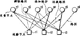
图4为例示删除、添加和转换路径的偶图;Figure 4 is a dual graph illustrating deletion, addition and conversion paths;
图5为有利于说明图4的对奇偶校验矩阵的操作的示意图;FIG. 5 is a schematic diagram useful for explaining the operation of the parity check matrix in FIG. 4;
图6为有利于说明图1中的LDPC解码器的解码处理的偶图;Fig. 6 is an even diagram useful in explaining the decoding process of the LDPC decoder in Fig. 1;
图7为例示包括具有不同的次数的变量节点的情况的偶图;FIG. 7 is a bigraph illustrating the case of including variable nodes with different degrees;
图8为例示调制方案为4元PAM时所得到的调制信号点和它们的抗错性的示意图;FIG. 8 is a schematic diagram illustrating modulation signal points obtained when the modulation scheme is 4-element PAM and their error resistance;
图9为例示图1中的无线电发送设备的工作情况的流程图;Fig. 9 is a flowchart illustrating the operation of the radio transmission device in Fig. 1;
图10为例示对4元PAM内的调制信号点执行标记的不同方式的示意图;FIG. 10 is a schematic diagram illustrating different ways of marking modulation signal points within a 4-element PAM;
图11为例示在调制方案为8元PSK时使用标记的映射的方式的示意图;FIG. 11 is a schematic diagram illustrating a manner of mapping using marks when the modulation scheme is 8-element PSK;
图12为例示按照本发明第二实施例设计的无线电发送设备和无线电接收设备的方框图;FIG. 12 is a block diagram illustrating a radio transmitting device and a radio receiving device designed according to a second embodiment of the present invention;
图13为例示图12中的无线电发送设备的工作情况的流程图;Fig. 13 is a flowchart illustrating the operation of the radio transmission device in Fig. 12;
图14为有利于说明根据频基通信信道状态确定映射模式的示意图;Fig. 14 is a schematic diagram useful for explaining the determination of the mapping mode according to the state of the frequency-based communication channel;
图15为有利于说明根据时基通信信道状态确定映射模式的示意图;Fig. 15 is a schematic diagram useful for explaining the determination of the mapping mode according to the state of the time-based communication channel;
图16为有利于说明按通信信道状态对LDPC比特序列的映射控制的示意图;Fig. 16 is a schematic diagram useful for explaining the mapping control of the LDPC bit sequence according to the state of the communication channel;
图17为例示图12所示的无线电发送设备和无线电接收设备的工作实例的示意图;FIG. 17 is a schematic diagram illustrating an example of the operation of the radio transmitting device and the radio receiving device shown in FIG. 12;
图18为例示按照本发明第三实施例设计的无线电发送设备和无线电接收设备的方框图;FIG. 18 is a block diagram illustrating a radio transmitting device and a radio receiving device designed according to a third embodiment of the present invention;
图19为例示按照本发明第三实施例的变型设计的无线电发送设备和无线电接收设备的方框图;FIG. 19 is a block diagram illustrating a radio transmitting device and a radio receiving device according to a modified design of the third embodiment of the present invention;
图20为例示按照本发明第四实施例设计的无线电发送设备和无线电接收设备的方框图;FIG. 20 is a block diagram illustrating a radio transmitting device and a radio receiving device designed according to a fourth embodiment of the present invention;
图21为有利于说明图20中所示的无线电发送设备执行的排序、分组和映射的偶图;FIG. 21 is a diagram useful in explaining the sorting, grouping, and mapping performed by the radio transmission device shown in FIG. 20;
图22为例示按照本发明第四实施例的第一变型设计的无线电发送设备和无线电接收设备的方框图;FIG. 22 is a block diagram illustrating a radio transmitting device and a radio receiving device designed according to a first modification of the fourth embodiment of the present invention;
图23为有利于说明图22中所示的无线电发送设备执行的排序、分组和映射的偶图;FIG. 23 is a diagram useful in explaining the sorting, grouping, and mapping performed by the radio transmission device shown in FIG. 22;
图24为例示按照本发明第四实施例的第二变型设计的无线电发送设备和无线电接收设备的方框图;FIG. 24 is a block diagram illustrating a radio transmitting device and a radio receiving device designed according to a second modification of the fourth embodiment of the present invention;
图25为有利于说明图24中所示的无线电发送设备执行的排序、分组和映射的偶图;FIG. 25 is a diagram useful in explaining the sorting, grouping, and mapping performed by the radio transmission device shown in FIG. 24;
图26为例示按照本发明第五实施例设计的无线电发送设备和无线电接收设备的方框图;以及FIG. 26 is a block diagram illustrating a radio transmitting device and a radio receiving device designed according to a fifth embodiment of the present invention; and
图27为例示图26中所示的无线电发送设备执行的收缩的模式的偶图。FIG. 27 is an even diagram illustrating a mode of contraction performed by the radio transmission device shown in FIG. 26 .
具体实施方式Detailed ways
下面将结合附图详细说明按照本发明的实施例设计的映射使用LDPC码的编码比特的方法、发送和接收设备以及执行这种方法的程序。A method for mapping coded bits using LDPC codes, a sending and receiving device, and a program for executing the method designed according to the embodiments of the present invention will be described in detail below with reference to the accompanying drawings.
首先,说明这些实施例所涉及的用低密次数奇偶校验(LDPC)码作为纠错码的无线电数字通信系统。在这种系统中,无线电发送设备通过向一个LDPC编码器输入数字数据和将它们指配给各自的调制信号点,产生一系列编码比特序列。另一方面,无线电接收设备根据无线电发送设备指配给调制信号点的每个编码比特序列与相应的纠错码之间的关系从由调制信号点接收的信息获取每个编码比特序列的似然信息。此后,无线电接收设备用似然信息对每个接收到的编码比特序列解码,得到想要的数字数据。First, a radio digital communication system using a low density parity check (LDPC) code as an error correction code according to these embodiments will be described. In such a system, radio transmitting equipment generates a series of encoded bit sequences by inputting digital data to an LDPC encoder and assigning them to respective modulation signal points. On the other hand, the radio receiving device acquires likelihood information of each coded bit sequence from information received by the modulated signal point based on the relationship between each coded bit sequence assigned to the modulation signal point by the radio transmitting device and the corresponding error correction code . Thereafter, the radio receiving device uses the likelihood information to decode each received coded bit sequence to obtain the desired digital data.
在这种无线电通信系统内,用例如M元相移键控(PSK)、M元正交调幅(QAM)、M元脉冲幅次数调制(PAM)、M元调幅/调相(AMPM)、M元脉冲位置调制(PPM)、正交频分多路复用(OFDM)、码分多址(CDMA)或超宽带调制(UWB)设置上面提到的调制信号点。In such radio communication systems, for example, M-ary phase shift keying (PSK), M-ary quadrature amplitude modulation (QAM), M-ary pulse amplitude modulation (PAM), M-ary amplitude/phase modulation (AMPM), M-ary Elemental Pulse Position Modulation (PPM), Orthogonal Frequency Division Multiplexing (OFDM), Code Division Multiple Access (CDMA), or Ultra Wideband Modulation (UWB) sets the modulation signal points mentioned above.
第一实施例first embodiment
下面将结合图1说明按照第一实施例设计的无线电发送设备和无线电接收设备。图1为无线电发送设备和无线电接收设备的方框图。A radio transmission device and a radio reception device designed according to the first embodiment will be described below with reference to FIG. 1. FIG. Fig. 1 is a block diagram of a radio transmitting device and a radio receiving device.
标为10的无线电发送设备适当地将用LDPC编码器编码的各比特序列映射到一些调制信号点,以使它们的抗错性最佳化。由图1可见,无线电发送设备10包括LDPC编码器11、排序单元12、交织单元13、映射单元14和多元发射信号调制器15。The radio transmission equipment referenced 10 suitably maps the respective bit sequences coded with the LDPC coder to modulation signal points in order to optimize their error resistance. It can be seen from FIG. 1 that the
LDPC编码器11接收到发送数据后,根据生成矩阵G对它进行LDPC编码。生成矩阵G定义为一个在一个预定的奇偶校验矩阵H下满足H×G=0的矩阵。执行LDPC编码后得到满足V×G=C的C,其中V表示构成发送数据的一个数字数据序列。这个“C”是一个LDPC编码比特序列,称为编码比特序列。After receiving the transmitted data, the
排序单元12按照从奇偶校验矩阵H得到的变量节点的次数对所得到的编码比特序列排序。从奇偶校验矩阵H得出的每个变量节点的次数与奇偶校验矩阵H的相应列向量内为“1”的元的个数相应。具体将就图3A和图3B所示的奇偶校验矩阵H进行说明。在这两个图中,奇偶校验矩阵H的每个列与一个变量节点相应,即第一至第六列与变量节点n1,n2,…,n6相应。在图3A所示的奇偶校验矩阵中,所有的变量节点n1,n2,…,n6的次数都为2。可是,在图3B所示的奇偶校验矩阵中,变量节点n1、n2、n3、n4、n5和n6的次数分别为3、3、3、1、1和1。在如图3B所示的不是所有的变量节点具有相同的次数的情况下,排序单元12就对所得到的编码比特序列排序。The sorting
此外,每个用从奇偶校验矩阵H得到的生成矩阵G编码的比特与一个变量节点相应。因此,奇偶校验矩阵H内的每个变量节点的次数可以认为与每个编码比特序列的每个比特相应。排序单元12考虑每个变量节点的次数是相应编码比特的次数,从而对编码比特序列排序。排序按照升幂或降幂的次序执行。在图3B所示的这个例子中,在按升幂执行排序时,变量节点排成n6、n5、n4、n3、n2和n1的次序。In addition, each bit coded with the generator matrix G obtained from the parity check matrix H corresponds to a variable node. Therefore, the frequency of each variable node in the parity check matrix H can be considered to correspond to each bit of each coded bit sequence. The sorting
排序单元12还将每个排好的编码比特序列分成与无线电发送设备10内所用的调制方案相应的预定个组。与调制方案相应的组数例如为在调制信号点之间不同的抗错级别数。例如,在4元PAM的情况下,每个排好的编码比特序列分成两个组,而在8元PSK的情况下分成三个组。Sorting
交织单元13以排序单元12分好的编码比特序列组为单位执行交织。交织单元13不是一个必需的单元,可以省去。也就是说,经排序单元12处理的编码比特序列可以直接输出给映射单元14。The
映射单元14为每个调制信号点指配一组编码比特序列。具体地说,按照与发送方所用的调制方案相应的抗错级别将编码比特序列组指配给各自的调制信号点。例如,如图11所示,用标志X、Y和Z进行标记。在上面提到的有n6和n5、n4和n3、n2和n1三个组的情况下,将它们分别指配给X、Y和Z。怎样为标志指配组由调制方案和/或通信信道确定。例如,某一个指配结果对一个高斯噪声通信信道呈现为具有很好的特性,但是对于一个例如存在衰落的通信信道就不总是呈现具有最佳特性。在图11这种情况下,标志Z呈现最低的抗错性,而标志X和Y呈现相同的高于标志Z的抗错性。图11中的编码比特的次数按照n6和n5、n4和n3、n2和n1的次序减小。此外,一个编码比特的次数越大,校正错误的可能性就越高。这是因为次数越大,一个通信信道上可用的似然信息通常就越多。在图11的情况下,具有最低通信抗错性的编码比特序列组指配给具有最高通信抗错性的标志。类似,具有第二最低通信抗错性的编码比特序列组指配给具有第二最高通信抗错性的标志。也就是说,在这种情况下,将一个编码比特序列内的一个呈现高抗错性的变量节点,即一个具有高的次数的变量节点,指配给一个状况不良的副载波。相反,将一个编码比特序列内的一个呈现低抗错性的变量节点,即一个具有低的次数的变量节点,指配给一个状况良好的副载波。因此,整个系统的抗错性得到增强。The
如上面所述那样映射LDPC编码器编码的比特序列避免了LDPC编码器11将一个低抗错的比特序列,如随机交织编码比特序列,草率地指配给发送方的一个低抗错的调制信号点。这样,可以建立一个更为可靠的用LDPC码的通信系统。Mapping the bit sequence encoded by the LDPC encoder as described above prevents the
多元发射信号调制器15用排序单元12执行分组时所参考的调制方案和映射单元14执行映射时所参考的调制方案对映射单元14输出的信号进行调制。所得到的调制信号发送给无线电接收设备50。The multi-element transmit
另一方面,无线电接收设备50包括接收信号解调器51、检波器52、去交织单元53、反排序单元54和LDPC解码器55,如图1中所示。On the other hand, the radio receiving device 50 includes a received
接收信号解调器51接收到无线电发送设备10发送的信号后,就对它进行解调。检波器52指定指配给每个调制信号点的编码比特,得出每个与所指定的编码比特相应的接收比特的似然值。一个接收比特的似然值为指出这个比特是否为0(或者是否为1)的概率。The
去交织单元53对接收比特序列的各比特的似然值执行去交织。去交织单元53与交织单元13相应。如果没有交织单元13,就不用去交织单元53。在这种情况下,检波器52的输出直接输入反排序单元54。The
反排序单元54用与经去交织的比特序列相应的变量节点的次数对经去交织的比特序列执行反排序。结果,将排序单元12所排的编码比特序列的比特的次序恢复到原来的次序。The
LDPC解码器55将从每个调制信号点接收到的编码比特的似然值指配给一个变量节点,根据最后汇聚的似然值估计出一个编码比特序列C′,满足C′×H=0,输出所估计的编码比特序列C′。The
下面将结合图2和图3A说明LDPC编码情况。The LDPC encoding situation will be described below with reference to FIG. 2 and FIG. 3A.
LDPC编码是一种根据例如如图2所示的偶图的编码方法。在LDPC编码方法中,构成与图2的偶图相应的奇偶校验矩阵H后,得出满足H×G=0的生成矩阵G。然后,得出满足V×G=C的编码比特序列C,其中V为一个发送数字数据序列。编码比特序列C指配和发送给一个调制信号点。此时,编码比特序列满足C×H=0。在接收方,通过选择一个满足C′×H=0的比特序列执行解码,其中C′表示从调制信号点接收到的含有一个错误的编码比特序列的似然性。因此,得到一个想要的数据序列。LDPC coding is a coding method based on a bipartite graph such as that shown in FIG. 2 . In the LDPC encoding method, after constructing the parity check matrix H corresponding to the even graph in FIG. 2 , a generator matrix G satisfying H×G=0 is obtained. Then, a coded bit sequence C satisfying V×G=C is obtained, where V is a transmitted digital data sequence. A coded bit sequence C is assigned and sent to a modulated signal point. At this time, the coded bit sequence satisfies C×H=0. On the receiving side, decoding is performed by selecting a bit sequence that satisfies C'*H=0, where C' represents the likelihood that a coded bit sequence containing an error is received from the modulated signal point. Thus, a desired data sequence is obtained.
可以产生一个与图2类似的偶图,与一个奇偶校验矩阵相应。也就是说,如果给定了一个偶图,就可以确定一个奇偶校验矩阵,反之亦然。例如,可以根据图2的这个偶图得到一个如图3A所示的奇偶校验矩阵。此外,在图2这个偶图中,图3A所示的奇偶校验矩阵H的这些列向量与图2所示的各变量节点相应,而图3A内的行向量与图2内的校验节点相应。此外,在奇偶校验矩阵H内为“1”的元的位置与将变量节点与校验节点连接的路径相应。例如,如果某一个元“1”的位置在矩阵的第二行与第三列的交点处,这就意味着在偶图内第二校验节点接到第三变量节点上。An even graph similar to that in Figure 2 can be generated, corresponding to a parity check matrix. That is, if an even graph is given, a parity-check matrix can be determined, and vice versa. For example, a parity check matrix as shown in FIG. 3A can be obtained according to the even graph in FIG. 2 . In addition, in the even graph shown in Figure 2, these column vectors of the parity check matrix H shown in Figure 3A correspond to the variable nodes shown in Figure 2, and the row vectors in Figure 3A correspond to the check nodes in Figure 2 corresponding. Also, the position of an element of "1" in the parity check matrix H corresponds to a path connecting a variable node and a check node. For example, if the position of a certain element "1" is at the intersection of the second row and the third column of the matrix, this means that the second check node is connected to the third variable node in the even graph.
利用以符号方式指出LDPC编码器11的编码操作的偶图可以获得与用变量节点的次数执行排序再按照通信信道状态执行分组相同的效果。这种方法下面将结合图4和5进行说明。The same effect as performing sorting with the number of times of variable nodes and then performing grouping according to the communication channel state can be obtained by using a bipartite graph that symbolically indicates the encoding operation of the
与排序相同的效果可以通过改变偶图内的路径获得。在这种情况下,由于可以通过改变奇偶校验矩阵H内元“1”的位置来改变次数的分布,因此可以省略用排序标记抗错性。此外,在这种情况下,必须按照奇偶校验矩阵H的改变情况改变生成矩阵G的元。可以通过按照通信信道状态改变奇偶校验矩阵的元“1”的数目来改变抗错性。The same effect as sorting can be obtained by changing the paths in the bipartite graph. In this case, since the distribution of the number of times can be changed by changing the position of the element "1" in the parity check matrix H, it is possible to omit marking error resistance with sorting. Also, in this case, it is necessary to change the elements of the generator matrix G according to the change of the parity check matrix H. The error resistance can be changed by changing the number of elements "1" of the parity check matrix according to the communication channel state.
下面将具体以图4所示的另一个偶图为例进行说明。图4示出了删除、添加和转换路径的情况。此外,图5示出了与删除、添加和转换图4的分部图中的路径相应的奇偶校验矩阵的改变。也就是说,在增加一个路径时,相应的矩阵元从“0”改变为“1”。在转换路径时,相应的两个的“0”和“1”互换。此外,在删除一个路径时,相应的矩阵元从“1”改变为“0”。由此可见,用变量节点的次数排序相当于置换列向量。The following will specifically take another even graph shown in FIG. 4 as an example for description. Figure 4 shows the cases of deleting, adding and converting paths. In addition, FIG. 5 shows changes in the parity check matrix corresponding to deletion, addition, and conversion of paths in the partition graph of FIG. 4 . That is, when adding a path, the corresponding matrix element changes from "0" to "1". When switching paths, the corresponding two "0"s and "1"s are swapped. Furthermore, when a path is deleted, the corresponding matrix element changes from "1" to "0". It can be seen that sorting by the number of variable nodes is equivalent to replacing the column vector.
下面将结合图6说明LDPC解码器55的解码情况。图6为一个有利于说明LDPC解码器55解码情况的偶图。The decoding of the
通过沿偶图内变量节点与校验节点之间的路径重复传送接收数据的似然信息对一个LDPC编码比特序列进行解码。在这种情况下,每个从一个调制信号点接收到的似然性指配给相应的变量节点,从而从最后汇聚的似然值估计出一个满足C′×H=0的C′,作为解码结果输出。An LDPC coded bit sequence is decoded by repeatedly transmitting the likelihood information of the received data along the path between the variable node and the check node in the even graph. In this case, each likelihood received from a modulation signal point is assigned to the corresponding variable node, so that a C′ satisfying C′×H=0 is estimated from the final aggregated likelihood value as the decoding The result output.
下面将结合图7说明由于解码导致的各变量节点之间不同的抗误码性。The difference in error resistance between variable nodes due to decoding will be described below with reference to FIG. 7 .
在与图7不同的图2这个偶图中,每个变量节点具有两个路径,而每个校验节点具有四个路径。在这种情况下,所有变量节点的似然信息从两个校验节点获得,而所有校验节点利用来自四个变量节点的似然信息。由于在每双节点之间传送相同的信息量,因此在编码比特序列之间可以获得相同的抗错性。In the dual graph of FIG. 2 which is different from FIG. 7, each variable node has two paths, and each check node has four paths. In this case, the likelihood information for all variable nodes is obtained from two check nodes, while all check nodes utilize likelihood information from four variable nodes. Since the same amount of information is transferred between each pair of nodes, the same error resistance can be obtained between coded bit sequences.
相比之下,在图7这个偶图(与图3B所示的奇偶校验矩阵相应)中,从校验节点传送给变量节点不同的似然信息量。例如,在图7这个偶图中,左边三个变量节点各有三个路径,而右边三个变量节点各只有一个路径。因此,所涉及的右边三个变量节点它们的似然值,即它们的编码比特,根据比左边三个变量节点的情况少的似然信息量估计。这意味着这些变量节点具有不同的抗错性。In contrast, in the even graph of FIG. 7 (corresponding to the parity check matrix shown in FIG. 3B ), different amounts of likelihood information are transmitted from the check nodes to the variable nodes. For example, in the bigraph in Figure 7, each of the three variable nodes on the left has three paths, while each of the three variable nodes on the right has only one path. Therefore, their likelihood values of the three variable nodes on the right involved, ie their coded bits, are estimated based on less likelihood information than in the case of the three variable nodes on the left. This means that these variable nodes have different error resistance.
假设,一个无线电通信系统使用一种具有多个调制信号点的调制方案,或者在时基域和频基域指配到一个有衰落的通信信道上的各个比特具有不同的抗错性。在这些情况下,诸如将编码比特的差错模式分散的交织方法之类的方法只注意了调制信号点和衰落差错模式而没有考虑LDPC编码比特序列内的抗错模式。因此,即使执行诸如交织之类的处理,也并不总是能实现适当地分散抗错性。此外,即使在一个通信信道上分散差错模式,也不总是能增强LDPC码的抗错性。It is assumed that a radio communication system uses a modulation scheme with multiple modulation signal points, or that individual bits assigned to a communication channel with fading have different error resistances in the time-based and frequency-based domains. In these cases, methods such as interleaving methods that disperse the error patterns of coded bits only pay attention to modulation signal points and fading error patterns without considering error-resistant patterns within the LDPC coded bit sequence. Therefore, even if processing such as interleaving is performed, appropriate dispersion of error resistance cannot always be achieved. Furthermore, even spreading error patterns over a communication channel does not always enhance the error resistance of LDPC codes.
考虑到以上情况,第一实施例的无线电发送设备和无线电接收设备提供了一个将编码比特序列映射到调制信号点的优化模型和一个基于这种映射的交织设计模型,可用于使用LDPC码的无线电通信系统。这些模型即使在LDPC编码比特序列包括具有不同抗错性的序列时也是有用的。In view of the above, the radio transmitting device and the radio receiving device of the first embodiment provide an optimized model for mapping coded bit sequences to modulation signal points and an interleaving design model based on this mapping, which can be used for radios using LDPC codes Communication Systems. These models are useful even when the LDPC coded bit sequence includes sequences with different error resistance.
下面将结合图8说明采用四元PAM调制方案、使编码比特序列与各调制信号点相应的具体例子。A specific example of using the quaternary PAM modulation scheme to make the encoded bit sequence correspond to each modulated signal point will be described below with reference to FIG. 8 .
在如图8所示采用四元PAM调制方案的情况下,指配给各自的调制信号点的编码比特XY具有不同的抗错性。比特X只按照幅度是否低于某个元确定是否X=0(或者是否X=1),而比特Y必须按照幅度是否在某个范围内确定是否Y=0(或者是否Y=1)。确定幅度是否在某个范围内比确定幅度是否高于某个元更为困难。前者得到一个错误的结果的可能性更高。由此可见,在图8的情况下,比特X具有比Y高的抗错性。In the case of adopting a quaternary PAM modulation scheme as shown in FIG. 8 , coded bits XY assigned to respective modulation signal points have different error resistances. Bit X only determines whether X=0 (or whether X=1) according to whether the magnitude is lower than a certain element, and bit Y must determine whether Y=0 (or whether Y=1) according to whether the magnitude is within a certain range. Determining whether the magnitude is within a certain range is more difficult than determining whether the magnitude is above a certain dollar. The former is more likely to get a wrong result. It can be seen that, in the case of FIG. 8 , bit X has higher error resistance than Y.
如果一个用LDPC编码器11编码的编码比特序列中的与具有比较少的路径的变量节点相应的比特(即具有低抗错性的比特)指配为图8中的比特Y,那么很可能相应调制信号点也具有低抗错性,从而使整个系统的性能降低。然而,如果编码比特序列指配给调制信号点的方式能使得编码比特序列的抗错性与调制信号点的抗错性不相互削弱,那么采用LDPC码的整个通信系统就可以具有高的抗错性。If the bit corresponding to the variable node with relatively few paths (that is, the bit with low error resistance) in the encoded bit sequence encoded by
下面将结合图9说明图1所示的无线电发送设备10的工作情况。Next, the operation of the
例如,按照图9所示的流程,无线电发送设备10的具有一些在所连接的路径的数目上不同(即次数不同)的变量节点的LDPC编码器用相应LDPC码的奇偶校验矩阵H对每比特序列进行编码,从而将每个编码比特序列映射到一个相应的调制信号点。For example, according to the flow shown in FIG. 9, the LDPC encoder of the
首先,从奇偶校验矩阵H得到所有的变量节点的次数(步骤S1)。每个变量节点的次数可以从偶图或者从构成奇偶校验矩阵H的每个列向量内元“1”的数目得出,因为每个变量节点的路径数与奇偶校验矩阵H的每个列向量内的元“1”的数目相应。一个用从奇偶校验矩阵H得出的生成矩阵G编码的比特序列内的比特与变量节点直接相应。因此,奇偶校验矩阵H内的每个变量节点的次数可以认为与编码比特序列的每个比特的次数相应。First, the times of all variable nodes are obtained from the parity check matrix H (step S1). The number of times of each variable node can be obtained from the even graph or from the number of "1" elements in each column vector constituting the parity check matrix H, because the number of paths of each variable node is the same as each of the parity check matrix H The number of elements "1" in the column vector corresponds. The bits in a bit sequence coded with a generator matrix G derived from a parity-check matrix H directly correspond to variable nodes. Therefore, the frequency of each variable node in the parity check matrix H can be considered to correspond to the frequency of each bit of the coded bit sequence.
接着,排序单元12按照从奇偶校验矩阵H得出的变量节点的次数对所得到的编码比特序列排序(步骤S2)。排序的次序可以是升幂或降幂的。此外,奇偶校验矩阵H的列向量可以是也可以不是按照编码比特序列的排序那样排序的。这些也都不失普遍性。Next, the sorting
用在通信信道上相应调制信号点所要求的抗错级别,排序单元12还将根据变量节点的次数排序的编码比特序列分成一些组(步骤S3)。例如,在图6所示的四元PAM调制的情况下,指配给每个调制信号点的两个比特XY具有不同的抗错级别,即具有两个抗错级别。在图8这个例子中,排序单元12形成一个具有较大的次数的组和一个具有较小的次数的组。同样,在采用另一个调制方案的情况下,抗错级别通过配置调制信号点和将比特映射到各自的调制信号点来确定。此外,在用次数进行分组中,组内的节点是否具有相同的次数并不重要。The sorting
此后,交织单元13对编码比特以排序单元12产生的组为单位进行交织(步骤S4)。是否执行这种处理并不失普遍性。此后,映射单元14将成组的编码比特映射到各自的调制信号点(步骤S5)。在这种情况下,指配的是按照发送方所用的调制方案确定的抗错级别分组的编码比特。Thereafter, the
下面结合图10说明根据不同的标记过程将编码比特映射到各自的调制信号点的方法的一个例子。具体地说,图10示出了受到不同的标记过程的调制信号点的四元PAM情况。An example of a method for mapping coded bits to respective modulation signal points according to different marking processes will be described below with reference to FIG. 10 . Specifically, Fig. 10 shows the Quaternary PAM case of modulated signal points subjected to different marking processes.
在四元PAM的情况下,灰度标记和集合划分是典型的对调制信号点执行的二进制标记过程。在图10所示的灰度标记和集合划分中,指配给每个信号点的比特X和比特Y具有不同的出错概率。图10所示的灰度标记是与图8的类似的二进制标记,其中比特X具有比Y高的抗错性。这一点很容易从上面结合图8所说明的信号点和所标记的比特的判决区域看出。In the case of quaternary PAM, grayscale labeling and set partitioning are typically binary labeling processes performed on modulated signal points. In the grayscale marking and set division shown in FIG. 10, bit X and bit Y assigned to each signal point have different error probabilities. The gray scale mark shown in FIG. 10 is a binary mark similar to that of FIG. 8, where bit X has higher error resistance than Y. This is easily seen from the signal points and the decision regions of the marked bits explained above in connection with FIG. 8 .
另一方面,在集合划分中,比特X的出错概率高于比特Y的出错概率。然而,如果比特X得到恰当地判定,并确定比特X的一个子集,就进一步降低了比特Y的出错概率。利用这个特征,可以规定将每个变量节点指配给灰度标志和集合分区的标准。On the other hand, in set division, the error probability of bit X is higher than that of bit Y. However, if bit X is properly judged and a subset of bit X is determined, the probability of error for bit Y is further reduced. Using this feature, it is possible to specify criteria for assigning each variable node to a grayscale label and set partition.
如果如在图1中所示的无线电接收设备50内检波器52不能接收LDPC解码器55的确定结果,从通信信道取得的比特X和比特Y的可信次数直接影响解码特性。在图10的灰度标记中,将一个包括次数高的(即路径多的)变量节点的组指配给出错概率高的比特Y。另一方面,将一个包括次数低的(即路径少的)变量节点的组指配给出错概率低的比特X。结果,可以得到出色的出错率特性。此外,在图10的集合划分中,如果将一个包括次数低的变量节点的组映射为比特Y而将一个包括次数高的变量节点映射为比特x就可以得到良好的结果。If the
然而,如果检波器52如在图18中所示的稍后要说明的无线电接收设备70内那样可以接收LDPC解码器55的确定结果,在将一个包括次数高的变量节点的组指配给比特Y而将一个包括次数低的变量节点的组指配给比特X时,在集合划分中可以取得良好的出错率特性。另一方面,在灰度标记中,如果在图18的无线电接收设备70内执行与在无线电接收设备50内相同的指配,就可以取得良好的出错率特性。However, if the
如上所述,通过根据变量节点的次数分组,将一个编码比特序列,即多个变量节点,指配给位于多个调制信号点的具有不同出错概率的各二进制标志。因此,按照接收方的解码处理,甚至从同一个信号点也可得到不同的出错率特性。类似,在任何其他调制方案中,必须规定怎样按照对信号点的配置、对信号点执行的标记和所用的解码方法将通过标记调制信号分组的变量节点指配给调制信号点。在这个实施例中,将变量节点分组成与多个调制方案之间的标记相应,按照所用的调制方案找出对编码比特序列分组的方法和将编码比特序列指配给信号点的最佳组合。As described above, by grouping according to the number of variable nodes, one coded bit sequence, ie, a plurality of variable nodes, is assigned to binary symbols with different error probabilities located at a plurality of modulated signal points. Therefore, different error rate characteristics can be obtained even from the same signal point according to the decoding process on the receiving side. Similarly, in any other modulation scheme, it must be specified how the variable nodes grouped by marking the modulated signal are assigned to the modulated signal points according to the configuration of the signal points, the marking performed on the signal points and the decoding method used. In this embodiment, the variable nodes are grouped to correspond to labels between a plurality of modulation schemes, the method of grouping coded bit sequences and the best combination of assigning coded bit sequences to signal points are found according to the modulation scheme used.
第二实施例second embodiment
下面将结合图12说明按照本发明第二实施例设计的无线电发送设备20和无线电接收设备60。图12为例示无线电发送设备20和无线电接收设备60的配置的方框图。A radio transmitting device 20 and a radio receiving device 60 designed according to a second embodiment of the present invention will be described below with reference to FIG. 12 . FIG. 12 is a block diagram illustrating configurations of the radio transmission device 20 and the radio reception device 60 .
第二实施例的无线电发送设备20只是在还使用一个通信信道状态接收单元21方面与第一实施例的无线电发送设备10不同。此外,第二实施例的无线电接收设备60只是在还使用一个通信信道状态发送单元61方面与第一实施例的无线电接收设备50不同。在第一和第二实施例中,同样的标号所标的是同样的组成部分,同样的说明就不再重复。The radio transmitting apparatus 20 of the second embodiment differs from the
通信信道状态接收单元21从无线电接收设备60接收一个包括通信信道状态的信号。映射单元14按照接收到的通信信道状态确定需将多个编码比特序列映射到各自的调制信号点的映射模式。The communication channel state receiving unit 21 receives from the radio receiving device 60 a signal including the state of the communication channel. The
通信信道状态发送单元61根据接收信号解调器51接收到的信号检测由于衰落而引起的通信信道状态,将包括通信信道状态的信号发送给无线电发送设备20的通信信道状态接收单元21。此外,通信信道状态发送单元61可以按照接收到的通信信道状态确定需将多个编码比特序列映射到各自的调制信号点的映射模式,将它发送给无线电接收设备60。在这种情况下,通信信道状态接收单元21从无线电接收设备60接收到映射模式后,映射单元14按照接收到的映射模式执行映射。The communication channel state transmitting unit 61 detects the communication channel state due to fading from the signal received by the received
下面将结合图13说明无线电发送设备20的工作情况。图13为有利于说明无线电发送设备20的工作的流程图。Next, the operation of the radio transmission device 20 will be described with reference to FIG. 13 . FIG. 13 is a flowchart useful in explaining the operation of the radio transmitting apparatus 20. As shown in FIG.
首先,通信信道状态接收单元21从无线电接收设备60接收到一个包括通信信道状态的信号,从而无线电发送设备20得知通信信道在频基或时基恶化的状态(步骤S11)。映射单元14按照检测到的通信信道状态确定编码比特序列的映射模式(步骤S12)。一种确定映射模式的方法将稍后结合图14(涉及频基状态)和图15(涉及时基状态)进行说明。First, the communication channel state receiving unit 21 receives a signal including the state of the communication channel from the radio receiving device 60, so that the radio transmitting device 20 knows the state of the communication channel in frequency base or time base degradation (step S11). The
按照在步骤S12确定的映射模式,确定解码器的结构,LDPC编码器11接收发送数据,对之编码(步骤S13)。排序单元12按照从奇偶校验矩阵H得出的变量节点的次数对每个所得到的编码比特序列排序(步骤S14)。排序单元12然后将排好的编码比特序列分成与在无线电发送设备20内所用的调制方案相应的预定个组(步骤S15)。According to the mapping mode determined in step S12, the structure of the decoder is determined, and the
交织单元13以排序单元12所分的组为单位交织编码比特(步骤S16)。按照在步骤S12确定的映射模式,映射单元14将每个组内的每个编码比特映射到相应的调制信号点(步骤S17)。The
下面将结合图14和15说明在步骤S12所用的确定映射模式的方法。图14为有利于说明按照频基信噪比(SNR)确定将一个变量节点指配给某个副载波的示意图。图15为有利于说明按照时基SNR确定将一个变量节点指配给某个副载波的示意图。The method of determining the mapping mode used in step S12 will be described below with reference to FIGS. 14 and 15 . FIG. 14 is a schematic diagram useful for explaining the determination of assigning a variable node to a certain subcarrier according to the frequency-based signal-to-noise ratio (SNR). FIG. 15 is a schematic diagram useful for explaining the determination of assigning a variable node to a certain subcarrier according to the time-based SNR.
在一个具有图14所示的频率特性的多载波通信系统内,各副载波之间SNR(即,通信信道状态)是不同的。在这种情况下,将一个次数高的即具有高抗错性的变量节点指配给一个信道状态不良的副载波,而将一个次数低的即具有低抗错性的变量节点指配给一个信道状态良好的副载波。这样就可以防止整个多载波通信系统特性的恶化。In a multi-carrier communication system having the frequency characteristics shown in FIG. 14, SNR (ie, communication channel state) is different among subcarriers. In this case, a variable node with a high degree of error resistance is assigned to a subcarrier with poor channel state, and a variable node with a low degree of error resistance is assigned to a channel state Good subcarrier. This prevents deterioration of the characteristics of the entire multicarrier communication system.
同样,在一个具有如图15所示的变化时基特性的通信信道系统内,将一个包括在每个编码比特序列内的低抗错性的组指配给一个高SNR的时基点,而将一个高抗错性的组指配给一个低SNR的时基点。这样就可以防止整个多载波通信系统特性的恶化。Also, in a communication channel system having varying timing characteristics as shown in FIG. 15, a group of low error resistance included in each encoded bit sequence is assigned to a timing point of high SNR, while a Groups with high error tolerance are assigned to a timing point with low SNR. This prevents deterioration of the characteristics of the entire multicarrier communication system.
此外,在通信信道状态具有时基或频基循环的情况下,可以对以上所说明的映射方法执行适当的控制。这将结合图16进行说明。图16示出了按照通信信道状态对映射每个LDPC编码比特序列的控制。Furthermore, in case the communication channel state has a time-based or frequency-based cycle, appropriate control can be performed on the mapping method explained above. This will be described with reference to FIG. 16 . Fig. 16 shows the control of mapping each LDPC coded bit sequence according to the communication channel state.
在通信信道状态如图16所示那样改变时,通信信道状态接收单元21检测在一段目标时间内的时基通信信道状态。然后,单元21将在目标时间内的出错特性分成若干级别不同的组。排序单元12按照通信信道状态接收单元21所分的组将每个LDPC编码比特序列分组,再将这些组映射到各抗错级别。这使通信信道状态随时间的改变可以得到迅速处理,不需要按照通信信道状态改变编码器的结构,而只需要在发送方和接收方面利用涉及映射编码器的输出的信息。When the communication channel status changes as shown in FIG. 16, the communication channel status receiving unit 21 detects the time-based communication channel status within a target time. Then, the unit 21 divides the error characteristics within the target time into several levels different groups. The sorting
在通信信道状态具有时基或频基循环的情况下,可以按照通信状态执行差错控制,不需要改变编码器和交织单元的设置,而只需要设置按照通信信道状态映射每个用变量节点的次数排序的编码比特序列的开始位置。In the case that the communication channel state has a time-based or frequency-based cycle, error control can be performed according to the communication state, without changing the settings of the encoder and interleaving unit, but only needs to set the number of times to map each variable node according to the communication channel state The starting position of the sorted coded bit sequence.
下面将结合图17进一步说明结合图16所说明的无线电发送设备20和无线电接收设备60的工作实例。An example of the operation of the radio transmitting device 20 and the radio receiving device 60 explained with reference to FIG. 16 will be further described below with reference to FIG. 17 .
LDPC编码器11输出一个编码比特序列(步骤S21),排序单元12按照相应的次数对编码比特序列排序(步骤S22)后,按照SNR将排好的编码比特序列分成一些组(步骤S23)。此后,映射单元14例如按照副载波的状态将这些组映射到各副载波(步骤S24)。多元发射信号调制器15对映射的信号进行调制后发送给无线电接收设备60(步骤S25)。
在无线电接收设备60内,接收信号解调器51接收到来自无线电发送设备20的信号(步骤S26)后,通信信道状态发送单元61检测通信信道状态(步骤S27)。此后,确定一个指出怎样按照检测到的通信信道状态将这些组的编码比特映射到调制信号点的映射模式,将它发送给无线电发送设备20(步骤S28)。接收到这个映射模式后,无线电发送设备20按照这个映射模式执行映射(步骤S29)。此外,无线电发送设备20发送给无线电接收设备60的信号从这些组通过检波器52至反排序单元54解除(步骤S30)后,再由LDPC解码器55解码(步骤S31)。In the radio receiving device 60, after the received
在如上所述那样工作的无线电发送设备20内,不必用上行链路发送为按照通信信道重构编码器所需的所有涉及通信信道状态的信息。无线电发送设备20只要发送涉及从分组得出的映射模式的信息就足够了。因此,在下行链路方通常可以迅速采用适合通信信道状态的编码比特序列的映射模式。在这种情况下,如果应处理更详细的通信信道状态,就将分组模式设置成产生许多组,而如果特性的恶化可以抑制在某个范围内,就将分组模式设置成产生少数几个分组。这可以尽量减小映射的处理量,有利于按照通信信道状态对比特数据编码。In the radio transmission device 20 operating as described above, it is not necessary to transmit all the information related to the state of the communication channel required to reconstruct the coder according to the communication channel in the uplink. It is sufficient for the radio transmission device 20 to transmit information related to the mapping pattern derived from the packet. Therefore, the mapping mode of the coded bit sequence suitable for the communication channel state can usually be rapidly adopted on the downlink side. In this case, set the grouping mode to generate many groups if more detailed communication channel status should be handled, and set the grouping mode to generate few groups if the deterioration of characteristics can be suppressed within a certain range . This can minimize the processing load of the mapping, and is beneficial to encode bit data according to the state of the communication channel.
按照第二实施例,采用LDPC编码的无线电通信系统使用了检测由于例如衰落而引起的时基或频基通信信道状态的改变的装置。结果,可以按照通信信道的状态控制编码比特序列的映射,从而使信息可以得到更为准确的解码。According to a second embodiment, a radio communication system employing LDPC coding uses means for detecting changes in the state of a time-based or frequency-based communication channel due to, for example, fading. As a result, the mapping of coded bit sequences can be controlled according to the state of the communication channel, so that information can be decoded more accurately.
第三实施例third embodiment
下面将结合图18说明按照本发明第三实施例设计的无线电发送设备10和无线电接收设备70。图18为例示无线电发送设备10和无线电接收设备70的配置的方框图。A
第三实施例的无线电发送设备10与第一实施例的无线电发送设备10类似。另一方面,第三实施例的无线电接收设备70只是在还使用排序单元71、交织单元72和加权单元73方面与第一实施例的无线电接收设备50不同。在第一和第三实施例中,同样的标号所标的是同样的组成部分,同样的说明就不再重复。The
在第三实施例中,无线电接收设备70重复执行对一个接收信号的解码。In the third embodiment, the
排序单元71和交织单元72具有与排序单元12和交织单元13相同的结构,分别执行与反排序单元54和去交织单元53相反的操作。具体地说,排序单元71对变量节点的似然值排序,而交织单元72交织排好的似然值。The sorting
加权单元73根据变量节点的似然值计算出需加到检波器52内的接收信号的似然值上的权,将它输出给检波器52。检波器52按照这个权校正接收信号的似然值。The
因此,在第三实施例内,接收信号的似然值可以比在第一实施例内更为精确地计算,从而信息可以比在第一实施例内更为准确地得到解码。Therefore, in the third embodiment, the likelihood value of the received signal can be calculated more accurately than in the first embodiment, so that information can be decoded more accurately than in the first embodiment.
图19示出了第三实施例的一个变型。在这个变型中,无线电发送设备和无线电接收设备还使用了一个能检测通信信道状态的单元。也就是说,这个变型是第二和第三实施例的组合,因此以与组合第二和第三实施例得到的无线电通信系统同样的方式进行工作,从而具有与第三实施例相同的优点。Fig. 19 shows a modification of the third embodiment. In this variation, the radio transmitting device and the radio receiving device also use a unit capable of detecting the state of the communication channel. That is, this modification is a combination of the second and third embodiments, and thus operates in the same manner as the radio communication system obtained by combining the second and third embodiments, thereby having the same advantages as the third embodiment.
如上所述,按照第三实施例设计的采用LDPC码的无线电通信系统可以更为准确地对信息解码。As described above, the radio communication system using LDPC codes designed according to the third embodiment can decode information more accurately.
第四实施例Fourth embodiment
按照第四实施例设计的无线电通信系统不仅用与包括在每个编码比特序列内的比特相应的次数执行对每个编码比特序列的分组,而且还用包括在多个编码比特序列内的比特的次数对多个编码比特序列分组。The radio communication system designed according to the fourth embodiment not only performs grouping of each coded bit sequence by the number of times corresponding to the bits included in each coded bit sequence, but also uses the number of bits included in a plurality of coded bit sequences Number of times to group multiple coded bit sequences.
下面将结合图20说明在第四实施例的无线电通信系统内所用的无线电发送设备30和无线电接收设备90。The radio transmitting device 30 and the radio receiving device 90 used in the radio communication system of the fourth embodiment will be described below with reference to FIG. 20 .
第四实施例的无线电发送设备30只是在采用多个LDPC编码器、排序单元和交织单元方面与第一实施例的无线电发送设备10不同。具体地说,从图20可见,无线电发送设备30通过在无线电发送设备10上再添加另一个LDPC编码器31、排序单元32和交织单元33形成。也就是说,无线电发送设备30包括两个LDPC编码器、两个排序单元和两个交织单元。此外,第四实施例的无线电接收设备90只是在包括多个去交织单元、反排序单元和LDPC解码器方面与第一实施例的无线电接收设备50不同。在第一和第四实施例中,同样的标号所标的是同样的组成部分,同样的说明就不再重复。在无线电发送设备30内,使用数量与去交织单元、反排序单元和LDPC解码器的数量相同的LDPC编码器、排序单元和交织单元。在这个实施例中,如上所述,数量设置为两个。The radio transmission device 30 of the fourth embodiment differs from the
在第四实施例的无线电通信系统内,多个发送数据项由各自的LDPC编码器编码。在无线电发送设备30内,以发送数据项为单位对发送数据LDPC编码、排序和分组,映射单元14将从所有发送数据项得到的编码比特序列组映射到各自的调制信号点。In the radio communication system of the fourth embodiment, a plurality of transmission data items are encoded by respective LDPC encoders. In radio transmission device 30, transmission data LDPC-encoded, sorted, and grouped in units of transmission data items, mapping
具体地说,例如如图21所示,通过LDPC编码器11、排序单元12和交织单元13从两个发送数据项得到编码比特序列1和编码比特序列2。这些编码比特序列如包围变量节点的椭圆所示那样分组。编码比特序列1被分成两个组g1和g2,而编码比特序列2被分成两个分组g3和g4。此后,在映射这些组时,编码比特序列1和2的所有的组g1至g4同时映射到各自的调制信号点。Specifically, for example, as shown in FIG. 21 , coded
下面将结合图22说明第四实施例的第一变型。图22为例示按照第一变型设计的无线电发送设备40和无线电接收设备150的方框图。Next, a first modification of the fourth embodiment will be described with reference to FIG. 22 . FIG. 22 is a block diagram illustrating the radio transmitting device 40 and the radio receiving device 150 designed according to the first modification.
第一变型的无线电发送设备40只是在包括多个LDPC编码器和单个排序单元和交织单元上与无线电发送设备30不同。此外,第一变型的无线电接收设备150只是在包括多个LDPC解码器和单个反排序单元和去交织单元上与无线电接收设备90不同。在第一变型和第四实施例中,同样的标号所标的是同样的组成部分,同样的说明就不再重复。无线电发送设备40使用数量与无线电接收设备150内使用的LDPC解码器的数量相同的LDPC编码器。在这个变型中,数量设置为两个。The radio transmission device 40 of the first modification differs from the radio transmission device 30 only in including a plurality of LDPC encoders and a single sorting unit and interleaving unit. Furthermore, the radio receiving device 150 of the first modification differs from the radio receiving device 90 only in including a plurality of LDPC decoders and a single reverse sorting unit and deinterleaving unit. In the first modification and the fourth embodiment, the same reference numerals designate the same components, and the same descriptions will not be repeated. The radio transmission device 40 uses the same number of LDPC encoders as the number of LDPC decoders used in the radio reception device 150 . In this variant, the number is set to two.
同样在第一变型内,多个发送数据项由各自的LDPC编码器编码。然而,第一变型与第四实施例不同,在排序后不是以发送数据项为单位而是以两个LDPC编码的发送数据项为单位执行处理。Also within the first variant, a plurality of transmission data items are encoded by respective LDPC encoders. However, the first modification performs processing not in units of transmission data items but in units of two LDPC-coded transmission data items after sorting, unlike the fourth embodiment.
在无线电发送设备40内,每个发送数据项是LDPC编码的,而两个LDPC编码的发送数据项同时输入排序单元12。结果,以两个发送数据项为单位,由排序单元12将LDPC编码的发送数据合成并排序,再由交织单元13交织。另一方面,映射单元14同时将从所有发送数据得到的发送比特序列的组同时映射到各自的调制信号点。In the radio transmission device 40, each transmission data item is LDPC-coded, and two LDPC-coded transmission data items are input to the
具体地说,例如如图23所示,LDPC编码器11和31分别对输入的发送数据项编码,产生编码比特序列1而2。这两个编码比特序列同时输入排序单元12。在这个变型中,对编码比特序列1和2的所有变量节点,从变量节点n1到变量节点n12,进行分组。此后,在执行映射时,将从编码比特序列1和2得出的所有发送比特序列的组映射到各自的调制信号点。Specifically, for example, as shown in FIG. 23,
下面将结合图24说明第四实施例的第二变型。图24为例示按照第二变型设计的无线电发送设备100和无线电接收设备160的方框图。Next, a second modification of the fourth embodiment will be described with reference to FIG. 24 . FIG. 24 is a block diagram illustrating a
第二变型的无线电发送设备100只是在不使用LDPC编码器31上与第一变型的无线电发送设备40不同。在设备100内,输入发送数据项中的一些输入LDPC编码器11编码后,输入排序单元12。但是,其他一些输入发送数据项没有受到编码而直接输入排序单元12。The
此外,第二变型的无线电接收设备160只是在不使用LDPC解码器93上与第一变型的无线电接收设备150不同。在无线电接收设备160接收到编码数据时,LDPC解码器55对接收数据解码,而在它接收到没有编码的数据时就不使用LDPC解码器55。编码数据解码后,用涉及解码数据的信息从检波器52提取没有编码的数据。Furthermore, the
具体地说,例如如图25所示,某些发送数据作为一个不编码比特序列直接输入排序单元12,而其他发送数据首先输入LDPC编码器11,经编码后再作为一个编码比特序列输入排序单元12。排序单元12对不编码比特序列和编码比特序列排序,交织单元13将排好的比特序列交织。在排序单元12按次数对不编码比特序列和编码比特序列分组时,将不编码比特序列考虑为具有最小的次数来排序和分组。此后,映射单元14将每个编码比特序列的组映射到相应的调制信号点。Specifically, for example, as shown in FIG. 25 , some transmitted data are directly input into the sorting
如上所述,不仅对单个编码比特序列而且也对多个编码比特序列LDPC编码的第四实施例的无线电通信系统可以更为准确地对信息解码。As described above, the radio communication system of the fourth embodiment that LDPC-codes not only a single coded bit sequence but also a plurality of coded bit sequences can decode information more accurately.
第五实施例fifth embodiment
下面将结合图26说明按照第五实施例设计的无线电发送设备110和无线电接收设备170。A radio transmitting device 110 and a radio receiving device 170 designed according to the fifth embodiment will be described below with reference to FIG. 26 .
第五实施例的无线电发送设备110只是在还采用一个收缩单元1101上与第一实施例的无线电发送设备10不同。此外,第五实施例的无线电接收设备170只是在还包括一个去收缩单元1701上与第一实施例的无线电接收设备50不同。在第一和第五实施例中,同样的标号所标的是同样的组成部分,同样的说明就不再重复。The radio transmission device 110 of the fifth embodiment differs from the
收缩单元1101收缩掉由排序单元12分成的具有最高抗错性的编码比特序列组,使得无线电发送设备110不发送这个组。非常可能的是,具有最高抗错性的组可以通过纠错从一个与没有收缩掉的编码比特序列相应的接收信号中恢复。因此,不大可能数据通信由于收缩掉具有最高抗错性的组而中断。Pruning unit 1101 punctures the group of coded bit sequences with the highest error resistance, which is divided into by sorting
去收缩单元1701用来使与一个收缩的编码比特序列相应的似然值可以用作一个与一个接收信号相应的似然值。The depuncturing unit 1701 is used to make the likelihood value corresponding to a punctured encoded bit sequence available as a likelihood value corresponding to a received signal.
下面将结合图27说明一个编码比特序列的例子。在图27中,一个与所示变量节点n1、n2和n3相应的编码比特序列属于一个具有最高抗错性的组(次数为3)。此外,一个与变量节点n4、n5和n6相应的编码比特序列属于一个需发送的组(次数为1)。即使无线电发送设备110不发送具有最高抗错性的编码比特序列组(次数为3),无线电接收设备170也可以对这个具有最高抗错性的编码比特序列解码。这可以通过映射一个接收到的编码比特序列组(次数为1)和通过一个接至一个包括在具有最高抗错性的组(次数为3)内的变量节点的路径接收信息来实现。在这种情况下,可以减少实际发送的信息量,从而提高了传输率。An example of a coded bit sequence will be described below with reference to FIG. 27 . In FIG. 27, a coded bit sequence corresponding to variable nodes n1, n2, and n3 shown belongs to a group having the highest error resistance (the number of times is 3). Furthermore, a coded bit sequence corresponding to variable nodes n4, n5 and n6 belongs to a group to be transmitted (number of times 1). Even if the radio transmitting device 110 does not transmit the coded bit sequence group having the highest error resistance (the number of times is 3), the radio receiving device 170 can decode this coded bit sequence having the highest error resistance. This is achieved by mapping a received coded bit sequence group (order 1) and receiving information via a path leading to a variable node included in the group with the highest error resistance (order 3). In this case, the amount of information actually sent can be reduced, thereby increasing the transmission rate.
在第五实施例中,如果用从按次数对变量节点排序得出的抗错级别的次序的信息执行分组,一个具有高抗错性的收缩模式可以很容易通过收缩一些具有高抗错性的组检测出来。In the fifth embodiment, if grouping is performed with information on the order of error resistance levels derived from sorting variable nodes by the number of times, a contraction pattern with high error resistance can be easily reduced by shrinking some group detected.
在以上所说明的按照第五实施例设计的采用LDPC码的无线电通信系统内,由于可以通过收缩减少无线电发送设备110所发送的数据量,因此可以提高数据传输速次数,而且可以准确地对发送数据解码。In the above-described radio communication system designed according to the fifth embodiment using LDPC codes, since the amount of data transmitted by the radio transmission device 110 can be reduced by contraction, the data transmission rate can be increased, and the transmission can be accurately performed. Data decoding.
这些实施例的流程图例示了按照本发明的这些实施例设计的方法和系统。可以理解,这些流程图的各个方框和流程图中的一些方框的组合可以用一些计算机程序指令实现。这些计算机程序指令可以加载到一个计算机或其他可编程的设备上来产生一个机器,使得这些指令在计算机或其他可编程的设备上执行时可以生成实现在流程图方框内所规定的功能的装置。这些计算机程序指令也可以存储在一个计算机可读存储器内,命令一个计算机或其他可编程设备以特定的方式操作,使得这些存储在计算机可读存储器内的指令形成一种包括实现在流程图的方框内指定的功能的指令装置的产品。计算机程序指令也可以加载到一个计算机或其他可编程的设备上,使得一系列操作步骤可在计算机或其他可编程设备上执行,产生一个计算机可编程的设备,提供各个步骤,实现在流程图的方框内指定的功能。The flowcharts of these embodiments illustrate methods and systems designed in accordance with these embodiments of the invention. It will be understood that individual blocks of the flowcharts and combinations of some blocks in the flowcharts can be implemented by some computer program instructions. These computer program instructions can be loaded on a computer or other programmable equipment to produce a machine, so that these instructions, when executed on the computer or other programmable equipment, can produce the means for realizing the functions specified in the blocks of the flowchart. The computer program instructions may also be stored in a computer-readable memory, and instruct a computer or other programmable device to operate in a specific manner, so that the instructions stored in the computer-readable memory form a method including the method implemented in the flowchart. The function specified in the box is the product of the instruction device. Computer program instructions can also be loaded on a computer or other programmable equipment, so that a series of operation steps can be executed on the computer or other programmable equipment, resulting in a computer programmable equipment, providing various steps, realizing the Functions specified within the box.
熟悉该技术领域的人员很容易想到其他一些优点和变型。因此,本发明并不局限于在这里所示出和所说明的具体细节和典型实施例。所以,可以在不背离如所附权利要求和与这些权利要求等效的表述所给出的本发明的精神实质和范围的情况下作出各种修改。Other advantages and modifications will readily occur to those familiar with the technical field. Therefore, the invention is not limited to the specific details and typical embodiments shown and described herein. Accordingly, various modifications may be made without departing from the spirit and scope of the invention as set forth in the appended claims and the equivalents of such claims.
Claims (11)
Applications Claiming Priority (2)
| Application Number | Priority Date | Filing Date | Title |
|---|---|---|---|
| JP2004088088A JP3875693B2 (en) | 2004-03-24 | 2004-03-24 | Coded bit mapping method and transmission apparatus using LPC code |
| JP2004088088 | 2004-03-24 |
Publications (2)
| Publication Number | Publication Date |
|---|---|
| CN1674447A true CN1674447A (en) | 2005-09-28 |
| CN100479334C CN100479334C (en) | 2009-04-15 |
Family
ID=34991610
Family Applications (1)
| Application Number | Title | Priority Date | Filing Date |
|---|---|---|---|
| CNB2005100590118A Expired - Fee Related CN100479334C (en) | 2004-03-24 | 2005-03-24 | Mapping method for encoded bits using LDPC code, transmitting and receiving apparatuses employing this method |
Country Status (3)
| Country | Link |
|---|---|
| US (1) | US20050216821A1 (en) |
| JP (1) | JP3875693B2 (en) |
| CN (1) | CN100479334C (en) |
Cited By (16)
| Publication number | Priority date | Publication date | Assignee | Title |
|---|---|---|---|---|
| CN101610133A (en) * | 2008-06-17 | 2009-12-23 | 三星电子株式会社 | Low-density parity code encoding device and decoding device and encoding and decoding method thereof |
| CN101119178B (en) * | 2006-08-01 | 2010-08-25 | 华为技术有限公司 | Signal sending and receiving method and signal sending and receiving device |
| CN101971503A (en) * | 2008-03-03 | 2011-02-09 | Rai意大利无线电视股份有限公司 | Modulation and QAM constellation bit permutation patterns for LDPC coding |
| CN104579571A (en) * | 2015-01-15 | 2015-04-29 | 山东超越数控电子有限公司 | Data storage method based on LDPC encoding |
| CN105379125A (en) * | 2014-05-21 | 2016-03-02 | 索尼公司 | Data-processing device and data processing method |
| CN105379127A (en) * | 2014-05-21 | 2016-03-02 | 索尼公司 | Data processing device and data processing method |
| CN105379124A (en) * | 2014-05-21 | 2016-03-02 | 索尼公司 | Data-processing device and data processing method |
| CN105409130A (en) * | 2014-05-21 | 2016-03-16 | 索尼公司 | Data-processing device and data processing method |
| CN105556855A (en) * | 2013-09-26 | 2016-05-04 | 索尼公司 | Data processing device and data processing method |
| CN105556856A (en) * | 2013-09-26 | 2016-05-04 | 索尼公司 | Data processing device and data processing method |
| CN105556857A (en) * | 2013-09-26 | 2016-05-04 | 索尼公司 | Data processing device and data processing method |
| CN105556854A (en) * | 2013-09-26 | 2016-05-04 | 索尼公司 | Data processing device and data processing method |
| CN105580281A (en) * | 2013-09-26 | 2016-05-11 | 索尼公司 | Data processing device and data processing method |
| CN105580280A (en) * | 2013-09-26 | 2016-05-11 | 索尼公司 | Data processing device and data processing method |
| CN105594130A (en) * | 2013-09-26 | 2016-05-18 | 索尼公司 | Signal representing data, method and device for generating such signal and method and device for determining the represented data from such signal |
| CN109784455A (en) * | 2019-01-23 | 2019-05-21 | 青岛柯锐思德电子科技有限公司 | A kind of reel material strip mask method |
Families Citing this family (62)
| Publication number | Priority date | Publication date | Assignee | Title |
|---|---|---|---|---|
| KR100918763B1 (en) | 2003-11-14 | 2009-09-24 | 삼성전자주식회사 | Apparatus and Method for Channel Coding / Decoding Using Parallel Concatenated Low Density Parity Check Codes |
| JP4050726B2 (en) * | 2004-06-23 | 2008-02-20 | 株式会社東芝 | Decoding device |
| US7760880B2 (en) * | 2004-10-13 | 2010-07-20 | Viasat, Inc. | Decoder architecture system and method |
| KR20060097503A (en) | 2005-03-11 | 2006-09-14 | 삼성전자주식회사 | Channel Interleaving / Deinterleaving Device and Its Control Method in Communication System Using Low Density Parity Check Code |
| JP4177824B2 (en) * | 2005-03-16 | 2008-11-05 | 株式会社東芝 | Encoding method, decoding method, and encoding system |
| KR20070015997A (en) * | 2005-08-02 | 2007-02-07 | 삼성전자주식회사 | Signal transmission / reception apparatus and method using differentiated multilevel modulation and demodulation method in wireless mobile communication system |
| JP4808722B2 (en) * | 2005-09-06 | 2011-11-02 | Kddi株式会社 | Data transmission system and data transmission method |
| GB2430586B (en) * | 2005-09-14 | 2007-11-07 | Toshiba Res Europ Ltd | Wireless communications apparatus |
| JPWO2007080727A1 (en) * | 2005-12-09 | 2009-06-11 | 三菱電機株式会社 | Communication method and communication apparatus |
| GB2434946B (en) * | 2006-02-01 | 2008-07-23 | Toshiba Res Europ Ltd | Wireless communications apparatus |
| KR100950654B1 (en) * | 2006-03-03 | 2010-04-01 | 삼성전자주식회사 | Signal transceiving device and method in communication system using multiple input multiple output method |
| EP1998454A4 (en) * | 2006-03-17 | 2010-04-28 | Mitsubishi Electric Corp | COMMUNICATION DEVICE, DECODING DEVICE, INFORMATION TRANSMITTING METHOD, AND DECODING METHOD |
| JP4864535B2 (en) * | 2006-05-16 | 2012-02-01 | 三菱電機株式会社 | Transmission / reception apparatus and transmission / reception method |
| KR100987692B1 (en) | 2006-05-20 | 2010-10-13 | 포항공과대학교 산학협력단 | Signal transceiving device and method in communication system |
| FR2904499B1 (en) * | 2006-07-27 | 2009-01-09 | Commissariat Energie Atomique | METHOD FOR DECODING MESSAGES WITH ORDERING ACCORDING TO NEIGHBORHOOD RELIABILITY. |
| CN101115045B (en) * | 2006-07-28 | 2010-05-19 | 华为技术有限公司 | A multi-antenna transmission method and device |
| JP4856605B2 (en) * | 2006-08-31 | 2012-01-18 | パナソニック株式会社 | Encoding method, encoding apparatus, and transmission apparatus |
| KR100834650B1 (en) | 2006-09-04 | 2008-06-02 | 삼성전자주식회사 | Signal transceiving device and method in communication system |
| ES2319590B2 (en) * | 2006-09-08 | 2009-10-07 | Universidad De Cantabria | LDPC AND INTERLEAVER ENCODER FOR DVB-S2. |
| WO2008034287A1 (en) * | 2006-09-18 | 2008-03-27 | Juntan Zhang | An interleaving scheme for an ldpc coded 32apsk system |
| JPWO2008093423A1 (en) * | 2007-02-01 | 2010-05-20 | パイオニア株式会社 | Data signal processing apparatus and method |
| KR101348221B1 (en) * | 2007-03-16 | 2014-01-07 | 삼성전자주식회사 | Method and apparatus for transmitting signal in a communication system |
| JPWO2008132813A1 (en) * | 2007-04-17 | 2010-07-22 | パナソニック株式会社 | Wireless communication apparatus and wireless communication method |
| US20100195571A1 (en) * | 2007-07-31 | 2010-08-05 | Panasonic Corporation | Wireless Communication Device and Retransmission Judging Method |
| WO2009028886A2 (en) * | 2007-08-28 | 2009-03-05 | Samsung Electronics Co., Ltd. | Apparatus and method for transmitting and receiving data in a communication system using low density parity check codes |
| JP4856608B2 (en) * | 2007-09-07 | 2012-01-18 | 日本放送協会 | Transmission device, reception device, and transmission method |
| WO2009031529A1 (en) * | 2007-09-07 | 2009-03-12 | Nippon Hoso Kyokai | Transmitter, receiver, and transmitting method |
| TWI459724B (en) * | 2007-11-26 | 2014-11-01 | Sony Corp | Data processing device and data processing method |
| TWI390856B (en) * | 2007-11-26 | 2013-03-21 | Sony Corp | Data processing device and data processing method |
| US8312341B1 (en) | 2007-12-05 | 2012-11-13 | Marvell International Ltd. | Interleaved error correction coding for channels with non-uniform SNRs |
| KR101503058B1 (en) | 2008-02-26 | 2015-03-18 | 삼성전자주식회사 | Method and apparatus for channel encoding / decoding in a communication system using a low-density parity-check code |
| WO2010024914A1 (en) * | 2008-08-29 | 2010-03-04 | Thomson Licensing | System and method for reusing dvb-s2 ldpc codes in dvb-c2 |
| US20100067514A1 (en) * | 2008-09-15 | 2010-03-18 | Qualcomm Incorporated | Wireless communication systems with femto nodes |
| US8842604B2 (en) * | 2008-09-15 | 2014-09-23 | Qualcomm Incorporated | Wireless communication systems with femto nodes |
| KR101481435B1 (en) * | 2008-12-18 | 2015-01-12 | 삼성전자주식회사 | Method for signal mapping in a communication system using low density parity check codes and apparatus therefor |
| CN102404072B (en) * | 2010-09-08 | 2013-03-20 | 华为技术有限公司 | A method, device and system for sending information bits |
| JP2012151676A (en) * | 2011-01-19 | 2012-08-09 | Jvc Kenwood Corp | Decoding apparatus and decoding method |
| WO2013097088A1 (en) * | 2011-12-27 | 2013-07-04 | France Telecom Research & Development Beijing Company Limited | Method and system for mapping bit sequences |
| KR101978811B1 (en) * | 2012-01-02 | 2019-08-29 | 삼성전자주식회사 | Hierarchical modulation and demodulation apparatus and method thereof |
| US9203434B1 (en) | 2012-03-09 | 2015-12-01 | Western Digital Technologies, Inc. | Systems and methods for improved encoding of data in data storage devices |
| US8605383B1 (en) | 2012-05-21 | 2013-12-10 | Western Digital Technologies, Inc. | Methods, devices and systems for characterizing polarities of piezoelectric (PZT) elements of a two PZT element microactuator |
| US8972826B2 (en) | 2012-10-24 | 2015-03-03 | Western Digital Technologies, Inc. | Adaptive error correction codes for data storage systems |
| US9021339B2 (en) | 2012-11-29 | 2015-04-28 | Western Digital Technologies, Inc. | Data reliability schemes for data storage systems |
| US9059736B2 (en) | 2012-12-03 | 2015-06-16 | Western Digital Technologies, Inc. | Methods, solid state drive controllers and data storage devices having a runtime variable raid protection scheme |
| CN102982849B (en) * | 2012-12-05 | 2015-10-28 | 清华大学 | For the ECC decode control method that data store |
| CN103036646B (en) * | 2012-12-05 | 2016-03-30 | 清华大学 | For the ECC decode control method of data communication |
| US9122625B1 (en) | 2012-12-18 | 2015-09-01 | Western Digital Technologies, Inc. | Error correcting code encoder supporting multiple code rates and throughput speeds for data storage systems |
| US9619317B1 (en) | 2012-12-18 | 2017-04-11 | Western Digital Technologies, Inc. | Decoder having early decoding termination detection |
| US8966339B1 (en) | 2012-12-18 | 2015-02-24 | Western Digital Technologies, Inc. | Decoder supporting multiple code rates and code lengths for data storage systems |
| US9214963B1 (en) | 2012-12-21 | 2015-12-15 | Western Digital Technologies, Inc. | Method and system for monitoring data channel to enable use of dynamically adjustable LDPC coding parameters in a data storage system |
| US8797664B1 (en) | 2012-12-22 | 2014-08-05 | Western Digital Technologies, Inc. | Polarity detection of piezoelectric actuator in disk drive |
| JP6363882B2 (en) * | 2013-06-19 | 2018-07-25 | 日本放送協会 | Transmitting apparatus, receiving apparatus and transmission system |
| CN104753653B (en) * | 2013-12-31 | 2019-07-12 | 中兴通讯股份有限公司 | A kind of method, apparatus and reception side apparatus of solution rate-matched |
| JP6404621B2 (en) * | 2014-07-03 | 2018-10-10 | 日本放送協会 | Transmitting apparatus, receiving apparatus and transmission system |
| US9153283B1 (en) | 2014-09-30 | 2015-10-06 | Western Digital Technologies, Inc. | Data storage device compensating for hysteretic response of microactuator |
| KR102504550B1 (en) * | 2015-12-28 | 2023-02-28 | 삼성전자주식회사 | Apparatus and method for receiving signal in communication system supporting low density parity check code |
| US11356193B2 (en) | 2016-10-07 | 2022-06-07 | Idac Holdings, Inc. | Rate matching and HARQ with irregular modulation |
| US11296823B2 (en) * | 2017-05-30 | 2022-04-05 | Qualcomm Incorporated | Priority based mapping of encoded bits to symbols |
| CN114679185A (en) * | 2017-08-11 | 2022-06-28 | 中兴通讯股份有限公司 | Data encoding method and device |
| CN111865333B (en) * | 2020-08-06 | 2023-06-23 | 南京信息工程大学 | A bit-level puncturing method based on multi-element LDPC code rate compatibility |
| US11316532B1 (en) * | 2020-12-17 | 2022-04-26 | SK Hynix Inc. | Decoding of low-density parity-check codes with high-degree variable nodes |
| WO2025203486A1 (en) * | 2024-03-28 | 2025-10-02 | 三菱電機株式会社 | Optical transmission device, control circuit, and program storage medium |
Family Cites Families (13)
| Publication number | Priority date | Publication date | Assignee | Title |
|---|---|---|---|---|
| US5243629A (en) * | 1991-09-03 | 1993-09-07 | At&T Bell Laboratories | Multi-subcarrier modulation for hdtv transmission |
| US5949796A (en) * | 1996-06-19 | 1999-09-07 | Kumar; Derek D. | In-band on-channel digital broadcasting method and system |
| US5953376A (en) * | 1996-09-26 | 1999-09-14 | Lucent Technologies Inc. | Probabilistic trellis coded modulation with PCM-derived constellations |
| US6198776B1 (en) * | 1996-11-13 | 2001-03-06 | Motorola Inc. | Device and method for precoding data signals for PCM transmission |
| US6157678A (en) * | 1996-12-18 | 2000-12-05 | Lucent Technologies Inc. | Probabilistic trellis/coded modulation with PCM-derived constellations |
| JP2004503979A (en) * | 2000-06-16 | 2004-02-05 | アウェア, インコーポレイテッド | LDPC modulation system and method |
| US6981202B2 (en) * | 2001-01-08 | 2005-12-27 | Nokia Corporation | Method and system for allocating convolutional encoded bits into symbols before modulation for wireless communication |
| BR0110161A (en) * | 2001-02-21 | 2002-12-31 | Matsushita Electric Industrial Co Ltd | Hybrid file method with redisposition of signal constellation |
| US6633856B2 (en) * | 2001-06-15 | 2003-10-14 | Flarion Technologies, Inc. | Methods and apparatus for decoding LDPC codes |
| FR2837044A1 (en) * | 2002-03-11 | 2003-09-12 | St Microelectronics Sa | Modulation procedure for binary data includes determination of number of bits to load according to signal to noise ratio and error probability |
| AU2003256588A1 (en) * | 2002-07-03 | 2004-01-23 | Hughes Electronics Corporation | Bit-interleaved coded modulation using low density parity check (ldpc) codes |
| US6829308B2 (en) * | 2002-07-03 | 2004-12-07 | Hughes Electronics Corporation | Satellite communication system utilizing low density parity check codes |
| US7020829B2 (en) * | 2002-07-03 | 2006-03-28 | Hughes Electronics Corporation | Method and system for decoding low density parity check (LDPC) codes |
-
2004
- 2004-03-24 JP JP2004088088A patent/JP3875693B2/en not_active Expired - Fee Related
-
2005
- 2005-03-10 US US11/076,050 patent/US20050216821A1/en not_active Abandoned
- 2005-03-24 CN CNB2005100590118A patent/CN100479334C/en not_active Expired - Fee Related
Cited By (23)
| Publication number | Priority date | Publication date | Assignee | Title |
|---|---|---|---|---|
| CN101119178B (en) * | 2006-08-01 | 2010-08-25 | 华为技术有限公司 | Signal sending and receiving method and signal sending and receiving device |
| CN101971503A (en) * | 2008-03-03 | 2011-02-09 | Rai意大利无线电视股份有限公司 | Modulation and QAM constellation bit permutation patterns for LDPC coding |
| CN101971503B (en) * | 2008-03-03 | 2014-07-02 | Rai意大利无线电视股份有限公司 | Bit permutation patterns for LDPC coded modulation and QAM constellations |
| CN101610133A (en) * | 2008-06-17 | 2009-12-23 | 三星电子株式会社 | Low-density parity code encoding device and decoding device and encoding and decoding method thereof |
| CN101610133B (en) * | 2008-06-17 | 2014-06-18 | 三星电子株式会社 | Low-density parity code encoding device and decoding device and encoding and decoding method thereof |
| CN105580280A (en) * | 2013-09-26 | 2016-05-11 | 索尼公司 | Data processing device and data processing method |
| CN105580281A (en) * | 2013-09-26 | 2016-05-11 | 索尼公司 | Data processing device and data processing method |
| CN105594130A (en) * | 2013-09-26 | 2016-05-18 | 索尼公司 | Signal representing data, method and device for generating such signal and method and device for determining the represented data from such signal |
| CN105556854A (en) * | 2013-09-26 | 2016-05-04 | 索尼公司 | Data processing device and data processing method |
| CN105556857A (en) * | 2013-09-26 | 2016-05-04 | 索尼公司 | Data processing device and data processing method |
| CN105556855A (en) * | 2013-09-26 | 2016-05-04 | 索尼公司 | Data processing device and data processing method |
| CN105556856A (en) * | 2013-09-26 | 2016-05-04 | 索尼公司 | Data processing device and data processing method |
| CN105409130A (en) * | 2014-05-21 | 2016-03-16 | 索尼公司 | Data-processing device and data processing method |
| CN105379124A (en) * | 2014-05-21 | 2016-03-02 | 索尼公司 | Data-processing device and data processing method |
| CN105379125A (en) * | 2014-05-21 | 2016-03-02 | 索尼公司 | Data-processing device and data processing method |
| CN105379127A (en) * | 2014-05-21 | 2016-03-02 | 索尼公司 | Data processing device and data processing method |
| CN105409130B (en) * | 2014-05-21 | 2019-09-27 | 索尼公司 | Data processing device and data processing method |
| CN105379124B (en) * | 2014-05-21 | 2019-11-08 | 索尼公司 | Data processing device and data processing method |
| CN105379125B (en) * | 2014-05-21 | 2019-11-12 | 索尼公司 | Data processing device and data processing method |
| USRE49925E1 (en) | 2014-05-21 | 2024-04-16 | Saturn Licensing Llc | Data processing device and data processing method |
| CN104579571A (en) * | 2015-01-15 | 2015-04-29 | 山东超越数控电子有限公司 | Data storage method based on LDPC encoding |
| CN109784455A (en) * | 2019-01-23 | 2019-05-21 | 青岛柯锐思德电子科技有限公司 | A kind of reel material strip mask method |
| CN109784455B (en) * | 2019-01-23 | 2022-02-22 | 青岛柯锐思德电子科技有限公司 | Reel material belt labeling method |
Also Published As
| Publication number | Publication date |
|---|---|
| US20050216821A1 (en) | 2005-09-29 |
| JP3875693B2 (en) | 2007-01-31 |
| JP2005277784A (en) | 2005-10-06 |
| CN100479334C (en) | 2009-04-15 |
Similar Documents
| Publication | Publication Date | Title |
|---|---|---|
| CN1674447A (en) | Mapping method for encoded bits using LDPC code, transmitting and receiving apparatuses employing this method | |
| CN1269338C (en) | Sending device, receiving device, sending method and receiving method | |
| CN1379561A (en) | System and method of transmitting/receiving data in CDMA mobile communication system | |
| CN1268063C (en) | Apparatus and method for generating codes in a communication system | |
| CN1868145A (en) | Method and apparatus for space-time coding using low density parity check codes in a wireless communication system | |
| CN1898891A (en) | Apparatus and method for transmitting and receiving coded data by encoder having unequal error probability in mobile communication system | |
| CN1650527A (en) | Digital audio broadcasting method and apparatus using complementary pattern-mapped convolutional codes | |
| CN1703862A (en) | Receiving signals modulated according to a multilevel coding technique | |
| CN1713531A (en) | Decoding apparatus and method for decoding the data encoded with an LDPC code | |
| CN1893342A (en) | Multi-carrier HSDPA service transmission channel coding processing method and coding device | |
| CN1993892A (en) | Apparatus and method for encoding and decoding a block low density parity check code | |
| CN1806392A (en) | Apparatus and method for generating and decoding forward error correction codes having variable rate in a high-rate wireless data communication system | |
| CN1947368A (en) | Apparatus and method for coding/decoding block low density parity check code with variable block length | |
| CN1666442A (en) | Radio communication base station device, radio communication mobile station device, and radio communication method | |
| CN1247648A (en) | Error correction decoder for vocoding system | |
| CN1655491A (en) | Transmission device using bit permutation method | |
| CN1286541A (en) | Orthogonal frequency-division multiplexing communication apparatus and propagation path estimating method | |
| US20230179321A1 (en) | Transport block size determination | |
| CN1595922A (en) | Wireless communication system, and demodulation method and data rate control method therefor | |
| CN1886923A (en) | Wireless transmission device and peak power suppression method in multi-carrier communication | |
| CN1705237A (en) | Decoding apparatus and decoding circuit | |
| CN101053195A (en) | Method and transmitter structure for reducing ambiguity by repeated recombination in bit fields | |
| US20080279303A1 (en) | Repetition-Dependent Mapping For Higher Order Modulation Schemes | |
| CN101065910A (en) | Apparatus and method for interleaving channels in a mobile communication system | |
| CN1993912A (en) | Radio transmitting apparatus and radio transmitting method in multicarrier communication |
Legal Events
| Date | Code | Title | Description |
|---|---|---|---|
| C06 | Publication | ||
| PB01 | Publication | ||
| C10 | Entry into substantive examination | ||
| SE01 | Entry into force of request for substantive examination | ||
| C14 | Grant of patent or utility model | ||
| GR01 | Patent grant | ||
| C17 | Cessation of patent right | ||
| CF01 | Termination of patent right due to non-payment of annual fee |
Granted publication date: 20090415 Termination date: 20120324 |