Rotor-position in the switched reluctance machines is determined
Technical field
The present invention relates in the reluctance motor, especially but be not unique, the non-inductive device rotor-position in the switched reluctance machines is determined.
Background technology
The control of switched reluctance machines and operation are described in the paper of being submitted to by J M Stephenson and R JBlake in PCIM ' 93 meetings that the Nurnberg of Germany holds and the exhibition " The Characteristics; Design and Applications ofSwitched Reluctance Motors and Drives " in 21-24 day in June, 1993 generally, and above-mentioned paper is hereby incorporated by.In that piece paper, " copped wave " pattern and " pulse " pattern of switched reluctance machines excitation has been described, be respectively applied for the operation of motor under low speed and high speed.
The typical prior art drive unit schematically shows in Fig. 1.This comprises a kind of direct current (DC) power supply 11, and above-mentioned DC power supply 11 can be a storage battery, or exchanges (AC) power supply through over commutation and filtering.The dc voltage that is provided by power supply 11 is under the control of electronic control unit 14, and the phase winding 16 that is striden across motor 12 by a power converter 13 is connected.One of many known converters topologys shown in Figure 2, wherein the phase winding 16 of motor is connected in series with two switching devices 21 and 22 between bus 26 and 27. Bus 26 and 27 is referred to as transducer " DC interconnection ".Energy recovery diode 23 and 24 is connected on the winding, when disconnecting with convenient switch 21 and 22, winding current can be flow back on the DC interconnection.A capacitor 25 that is called " DC interconnection capacitor " is connected between the DC interconnection with source or place as any alternating current component (that is so-called " pulsating current ") of DC interconnection electric current, and power supply be drawn or be returned to any alternating current component of above-mentioned DC interconnection electric current can not from power supply.In fact, capacitor 25 can comprise several series connection and/or capacitor in parallel, and in the place that employing is connected in parallel, wherein a part of element can be distributed in the whole transducer.A resistor 28 is connected in series with following switch 22, so that a current feedback signal is provided.A polyphase system adopts " phase core (leg) " of several Fig. 2 usually, and above-mentioned several " phase cores " are connected in parallel, so that each phase of exciting electric.
The performance of switched reluctance machines partly depends on the accurate timing that encourages mutually with respect to rotor-position.The detection of rotor-position is the transducer 15 that utilizes Fig. 1 to schematically show routinely, as the band fluted disc that is installed in a kind of rotation on the rotor reaches the band fluted disc of above-mentioned rotation and a kind of optics or the electromagnetic inductor collaborative work that are installed on the stator.The expression rotor produces and is added on the control circuit with respect to the pulse train of the position of stator, so that excitation mutually to be provided accurately.This system is simple, and can be in many application works fine.Yet rotor-position sensor has increased the total cost of device, some extra being electrically connected is added on the motor, and is a kind of potential source of unreliability therefore.
Now propose the whole bag of tricks and saved rotor-position sensor.Some method in these methods has been done commentary by W F Ray and I H Al-Bahadly in " Sensorless Methods for Determiningthe Rotor Position of Switched Reluctance Motors ", above-mentioned commentary be published in European PowerElectronics Conference minutes the 6th volume 7-13 that Britain Brighton1993 holds on September-16 on the 13rd capable in, this commentary is hereby incorporated by.
In these methods of estimating to be proposed for the conventional rotor-position in the electric drive-type motor, many methods are all utilized and are measured one mutually or phase magnetic flux chain (that is institute's making alive is to integration of time) and electric current in heterogeneous.The position utilizes as the understanding of the variation inductance in the motor of the function of angle and electric current and calculates.This specific character can be used as a kind of magnetic flux chain/angle/ammeter storage, and illustrates with curve chart in Fig. 3.The storage of this data comprises that this expense is used for the insertion of data between memory point with a kind of big memory array and/or other overhead.
Some method is utilized this data under low speed, wherein " copped wave " Current Control is the main control strategies that is used to change the torque of generation.Copped wave is controlled among Fig. 4 (a) and illustrates with curve chart, wherein is illustrated in the interior electric current of a phase inductance periodic regime and the waveform of inductance.(notice that variation inductance illustrates with Utopian form.) these methods adopt in the phase that does not produce torque (that is a particular moment not directly by those phases of power supply excitation) usually and diagnose driving pulse.A kind of method that is suitable for low cruise is the method that is proposed in " Accurate SensorlessRotor Position Detection in an S R Motor " by N M Mvungi and J M Stephenson, its be published in Italian Firenze in 1991 European Power Electronics Conference minutes the 1st the volume 390-393 capable in, be hereby incorporated by.These methods the best of working under lower speed, it is little wherein being compared with the whole cycle time in an inductance cycle by the shared time span of a diagnosis pulse.When speed rose, pulse occupied the major part in cycle, and unavailable that of very fast arrival securing position information.
Other method is to move with " pulse " incentive mode under fair speed.This pattern is shown in Fig. 4 (b), and wherein electric current and inductance waveform are to illustrate in a phase inductance periodic regime.These methods are not being disturbed operating voltage and the electric current that monitors current phase under the normal operation.A kind of method of typical fair speed has been done introduction in International Patent Application WO 91/02401, it is hereby incorporated by.
Two switches are opposite with disconnecting simultaneously, have in the certain situation advantageously than θ
OnPostpone an angle θ
fDisconnect second switch, make electric current wind switch, phase winding and formed looped cycle of diode by closure.Typical waveform is shown in Fig. 4 (c).This technology is called " inertia operation (freewheeling) ", and for a variety of causes uses, reduces comprising peak current restriction and noise.
For two-dimensional array that must the store electricity machine data there not being under the situation of position sensor operation is a significant disadvantages.Proposed some methods that substitute, it is the needs of the information of reference with the angle that these methods have been saved great majority, stores data and only replace under an angle.A kind of such method has been done introduction in European patent application EP 0573198A (Ray), above-mentioned patent application is hereby incorporated by.This method purpose is by determine phase magnetic flux chain and the electric current under a predetermined angular according to the bias adjustment diagnostic points of the desired point of the distance that calculates.The magnetic flux chain will be by being added to voltage measuring value (to the time) Integral Estimation that goes up mutually.Two one dimension tables of storage in above preferred embodiment, one of them is at magnetic flux chain-electric current of doing under the rotor angle of benchmark, and another is the difference-electric current of magnetic flux chain with respect to rotor angle.By monitoring phase voltage and electric current, can estimate apart from the deviation of prediction angle by means of look-up table, and correspondingly regulating system operation.
When electric current drops to zero and phase winding when no longer being coupled any magnetic flux, for fear of the integrator drift of magnetic flux chain (owing to the undesirable of undesirable noise and integrator in the system causes), the end in each conduction cycle is set at it zero.This method is a kind of " predictor/corrector " method, because it predicts at the beginning when rotor is in the reference position, when it is thought when having arrived the reference position, measure the parameter of electric machine, and utilize these measurement results to detect error in the prediction, thereby by adopting new prediction to carry out corrective action to next reference position.
The phase inductance cycle of switched reluctance machines is the inductance period of change for this phase or each phase, for example between each rotor pole and relevant stator poles separately are fully to punctual limit.Fig. 4 (a) illustrates the inductance distribution map of ideal form, and in fact the turning of distribution map owing to aerial magnetic flux edge effect and ferromagnetic path saturated becomes circle.
Known in single pulse mode the phase current waveform shape of switched reluctance machines relevant with the inductance distribution map of phase winding.Especially because the beginning of the overlapping inductance distribution map rising part that begins to cause between stator and the rotor pole, corresponding to when phase current phase inductance in the cycle from rising to the upset when descending variation.The EP1109309A that is hereby incorporated by has discussed this phenomenon, and utilizes intrinsic peak in the electric current as the basis of rotor position detecting method in that pulse is in service.
Yet, if not excitation on winding, for example motor is just in running down, perhaps since the history of the excitation of front because of noise or mechanical disturbance is unreliable causes excitation to lose, then need method for detecting position, it is provided to the bumpless transfer of excitation with the estimated position and under needn't the situation of brake.The inventor understands, and needs a kind of non-inductive device control method, and described non-inductive device control method can be moved in very wide velocity interval under the situation of the excitation history of not knowing drive unit in advance.
Summary of the invention
The purpose of this invention is to provide a kind of stalwartness and cost-effective method of determining rotor-position under without the situation of rotor-position sensor.
The present invention limits in appended independent claims.Some preferable feature is described in the dependent claims.
In one form, the invention provides a kind of method and system, the continuous current that described method and system utilization is produced in a phase winding is determined the position of motion rotor, above-mentioned continuous current has waveform, and described waveform comprises relevant information basic time of the various major events of phase inductance in the cycle with motor.From these features one of them, may obtain rotor position information.
A benefit of the present invention is the electromagnetism distribution map that it does not need to know in advance motor, for example, and as shown in Figure 3.Therefore, this method does not need to store in a large number data, and can be very healthy and strong under the situation that has noise on the waveform, and described method derives the position from this waveform.This is opposite with above-mentioned prior art.
One embodiment of the present of invention provide a kind of method that is identified for the rotor-position of motor, above-mentioned motor has stator and rotor, said stator has at least one phase winding, said method comprises: form the continuous current in the phase winding when rotor motion, this electric current has the waveform relevant with the inductance distribution map of motor, and described waveform changed with the rotor-position cycle; The predetermined characteristic of detection waveform in the cycle; And from the existence of feature, obtain rotor position information.
Preferably, motor is a switched reluctance machines.
Preferably, continuous current forms by for example striding the added potential pulse of phase winding.Because each potential pulse only is used for forming continuous current, the appearance of each potential pulse can be asynchronous.For this reason, they needn't be in reference aspect phase inductance cycle any.Be added to preferably potential pulse of this voltage distribution map of going up mutually, and the opposite polarity voltage than low amplitude between each pulse.
The estimated rotor position based on a kind of feature easily be the electric current upset consistent with the beginning of the inductance that rises in the phase inductance distribution map.
The present invention is particularly useful for the running down motor, because the smaller electric current of being inducted in single-phase winding has waveform, described waveform comprises to be determined to see in the equivalent current waveform when all required information of rotor-position, above-mentioned information can also be worked as the motor operation in addition.
Description of drawings
The present invention can try out with many modes, and the some of them mode will be used as example now and describe with reference to accompanying drawing, wherein:
Fig. 1 illustrates a kind of typical prior art switch magnetic resistance driving device;
Fig. 2 illustrates the known topology of a phase of the transducer among Fig. 1;
Fig. 3 is illustrated under the situation of rotor-position as a parameter, the curve of typical magnetic flux chain and phase current;
Fig. 4 (a) is illustrated in a kind of typical motor running current waveform in the copped wave control;
Fig. 4 (b) is illustrated in a kind of typical motor running current waveform in the pulse control;
Fig. 4 (c) is illustrated in a kind of typical motor running current waveform in the pulse control that utilizes the inertia operation;
Fig. 5 illustrates in schematic form and embodies switch magnetic resistance driving device of the present invention;
Fig. 6 illustrates a kind of according to the described current waveform of one aspect of the present invention; And
Fig. 7 illustrates a kind of according to the described phase voltage waveform of one aspect of the present invention.
Embodiment
Exemplary embodiment to be illustrated adopts a kind of 2 phase switch reluctance drive units under the motor operational mode, but can use any number of phases, and drive unit can be under the motor operational mode, also can be under power generation mode.
Fig. 5 illustrates a kind of system, and described system is used to implement the present invention, has wherein embodied a kind of form of the present invention.Wherein, provide a power converter 13, be used for the control switch reluctance motor, above-mentioned power converter 13 is identical with the power converter shown in Fig. 1 usually.Control transformation device 13 be a controller 42, in the present embodiment, above-mentioned controller 42 comprises: a processor, especially a kind of digital signal processor 44 is such as one of them of Analog Devices2181 series; And relevant program and data storage 46.Some alternate embodiments can comprise the programming device of a kind of microprocessor or other form, and this is being well-known in the art.Processor moves with conventional method according to institute's stored program code in the memory 46, so that carry out method of the present invention.Shown 2 phase motors have a stator 30 and a rotor 32.Stator has 4 utmost points 50, twines phase winding 34/36 at above-mentioned 4 on extremely.Rotor has rotor pole 52, and in order to help starter motor, rotor has a ladder air gap 54.The ladder air gap is not important: the end face of each rotor pole can have a kind of curved profile of routine.One skilled in the art will recognize that, can be with a kind of motor, because the present invention is not specific to any specific motor topology with the different numbers of phases or utmost point combination.
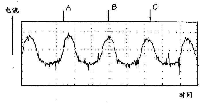
According to one embodiment of the present of invention, by on one's own initiative a voltage being injected a single-phase winding, and the electric current that above-mentioned voltage is inducted moves at the remainder inertia of whole phase cycle, obtain data flow from electric rotating machine, it is little that above-mentioned voltage ratio strides across the added driving voltage of winding usually.Voltage distribution map and especially potential pulse, so selected so that keep a continuous electric current in the phase winding.By injecting small voltage as pulse, producing definite rotor information required in the cycle phase current as a result with respect to the position of stator, The above results cycle phase current illustrates with the trace of Fig. 6.Method of the present invention is used on the motor, and described motor turns round (such as rotation), but not necessarily moving by excitation phase winding incoming call gas drive.This is called " running down ".This situation is the former a kind of special situation of difficult of just thinking to determine therein rotor-position owing to its dynamic property.Yet as appreciable in Fig. 6, the voltage that is injected produces the phase current waveform of one-period, and described phase current waveform presents the feature that rotor-position can therefrom be determined.
To the specific drive unit of being considered, injecting voltage size must be careful selected, but above-mentioned injecting voltage size has a mean value usually, and described mean value is lower than and is 10% of the added specified driving voltage of drive motors.Voltage is preferably by providing from main bus bar on the bus switch that pulse width modulation (PWM) is added to a phase.Perhaps, a low-tension supply of separating (pulsed or not variation in time) can be connected to going up mutually of an appointment.In both cases, add that positive voltage makes the magnetic flux chain of phase winding be risen by the speed that voltage swing was determined with a kind of.When removing voltage, the negative electricity pressure drop that is produced by the voltage drop sum of striding winding resistance, diode and switch makes magnetic flux descend with lower speed.Electric current reverts back to stable figure, always described stable figure positive and change with inductance distribution map cycle of winding, shown in the trace among Fig. 6, the trace among Fig. 6 is considered in more detail below.
Should be noted that when the full negative voltage of voltage bus is added on the winding there is not cycle portions, different when this runs well with motor.Voltage replaces between short high positive voltage that happens suddenly and long-standing much lower negative inertia working voltage, as shown in Figure 7.Very little continuous magnetic flux is arranged in winding; Electric current when the current ratio that is produced is normally moved is little; And epitrochanterian effective torque is zero.Therefore, the theoretical proposition, as long as effective torque is zero, the size of each potential pulse and duration just do not have the upper limit.Yet, if pulse rises to high level, the overslaugh that will become of the interrupted character of injecting voltage pulse.Overslaugh may for example produce torque pulsation or noise, and above-mentioned torque pulsation or noise may be unacceptable in some applications.The lower limit of voltage is the voltage of the continuous current in keeping mutually.
Fig. 6 illustrates phase current waveform actual oscillography trace under these conditions.Can note several characteristic about this trace.At first, there is sizable noise on signal, to exist.Although wherein a part may be the true indication of electric current in the winding, wherein a part is a measure error, and described measure error is by causing such as near the interference of switch motion to current measurement value.However, position probing of the present invention is for preventing that these phenomenons from being healthy and strong, and do not need special filtering usually.Secondly, current peak is inhomogeneous.This may be because various factors causes that above-mentioned factor comprises the pulsation on the power bus.In addition, it is healthy and strong that this method changes these because with the absolute current level be incomparable.
According to one embodiment of the present of invention, the existence of the crest that continuous rotor position information can be by detecting the phase current that initiatively injecting voltage pulse produced obtains.The method of various detection current waveform crests all is fine.According to a preferred embodiment of the present invention, the simplest form is with processor 44 programming so that to adopting the sample of Continuous Flow from the electric current of transducer 38, and with youngest sample and previous sample comparison.If two samples equate that then the size of current waveform does not change.Therefore, reach phase current and change (di/dt) in time for the point of zero-speed rate, described in EP1109309A, the identification of above-mentioned point is extremely overlapping point.Yet as if although detection zero di/dt likes a kind of ideal solution to non-inductive device problem, in fact it is restricted, and may be unreliable, mainly is owing to the noise on the current waveform that records causes.
A kind of more healthy and stronger method is to utilize a kind of method of slope detection, and the method for described slope detection detects and reaches the peak current beginning of slope downwards afterwards.Although this inserts delay inevitably when detecting extremely overlapping point, this delay is actually constant, and this can compensate in controller.Therefore controller can calculate to a nicety when run into the extremely overlapping point of the next one.
In this embodiment, in order to carry out slope detection, microprocessor 44 comprises a kind of algorithm that sample is compared (as in the above-mentioned execution) with previous sample.Yet equal samples is opposite mutually with searching two, and it has ignored all samples (promptly when waveform increases or be smooth) more than or equal to previous sample.In case reach the point of current sample, can assert that crest (0di/dt) puts process, and electric current descend with a negative slope now less than previous sample.This technology produces one and normally detects pulse at the non-inductive device of latter two sample of actual crest, and the sampling time is the known quantity of fixing.Can in the angle Control Software, compensate this known time of two sample cycles then.
Be programmed into the algorithm that detects the continuous negative slope on some samples in the processor by modification, rather than assert that first negative slope that is calculated is current waveform crest reality first sample afterwards, can realize improved performance.Such as, by from sample, searching two or more negative slope results and ignoring any zero result of variations (because such as the slow rate of change under low speed and bad analog/digital (A/D) resolution), can assert very safely that slope descends clearly.Detect pulse and after the 0di/dt point, also postpone minimum 3 samples, but because it is known time quantum, this can compensate in controller 42.
Because even do not need to understand approx rotor-position to implement the present invention's (not as many other method for detecting position), so can apply the pwm pulse of voltage at any some place of inductance in the cycle, that is they can be asynchronous with current waveform, makes to implement this method under the situation of not understanding spinner velocity.Close inspection Fig. 6 as can be seen, the asynchronous pwm pulse that adds is marked with A at trace, the some place of B and C takes place.Because some C is in the zone of carrying out slope detection, so the making alive pulse may produce a kind of false results when slope detection herein.This can be avoided by those zones that restriction is added to pulse in the current waveform, in above-mentioned those zones electric current less than peak value such as 50%.This value is not strict, but only as a rough filter, so that waveform more clearly is provided for the slope detection algorithm.
From above-mentioned explanation as can be seen, electric current is flowed in mutually, so that the detection position one.Whether this method exists electric current irrelevant with other in mutually owing to any reason.Yet, this method is applied to two-phase or multiphase simultaneously, therefore increase the speed of rotor position detection, may be favourable.If no matter the speed of rotor is upwards or downwards to change fast, then this may have special advantage.
Can recognize,, need a limited time quantum for the potential pulse with Fig. 7 forms for example continuous current of Fig. 6.If require to form electric current quickly, then originally the work period of potential pulse can increase, and then when reaching the desired level of electric current, reduces to one and produce enough webers so that electric current remains on the width of desired level.
The foregoing description detects extremely overlapping beginning, and the rotor-position of deriving thus.Other embodiment of the present invention detect other point on the inductance distribution map.For example,, can detect the position of maximum induction (Lmax) by detecting the middle part of trough in the current waveform, that is the point aimed at fully of rotor pole and stator poles.Can detect equally with related other point of inductance distribution map on the current waveform.Be also to be understood that this feature takes place in the one-period of waveform.Therefore, in order to detect, only need form electric current at one-period.Equally, can recognize that the cycle itself does not need continuously, such as, it can comprise some divided portion, above-mentioned each divided portion is observed by controller, so that detected characteristics.
Said method can on an equal basis advantageously be applied to as motor or as the motor of generator work.
It should be appreciated by those skilled in the art that without departing from the invention especially on the details of the algorithm in implementing controller, the various distortion of disclosed device all are possible.It is evident that also although above-mentioned technology is described about a kind of switched reluctance machines, it can be used for any periodically motor of inductance distribution map that has.Whether this method can be applicable to one and no matter there is excitation to be added to any other that may exist in the motor goes up mutually mutually.In addition, although the present invention is illustrated according to electric rotating machine, the present invention is comparably applicable to linear electric motors, and above-mentioned linear electric motors have the stator of track form and mobile moving-member thereon.Using word " rotor " to refer to the two movable part of electric rotating machine and linear electric motors in the art, and explaining by this way at this.Therefore, the explanation of some embodiment is to be used as example and hard-core purpose above.Those skilled in the art are not obviously carrying out under the situation of great change aforesaid operations, can carry out minor modifications to drive circuit.The present invention's plan is only limited by the scope of following claims.