[go: up one dir, main page]

CN1509525A - Automatic gain control system for multi-user OFDM digital transmission system using the electric grid - Google Patents

Automatic gain control system for multi-user OFDM digital transmission system using the electric grid Download PDF

Info

Publication number
CN1509525A
CN1509525A CNA028101170A CN02810117A CN1509525A CN 1509525 A CN1509525 A CN 1509525A CN A028101170 A CNA028101170 A CN A028101170A CN 02810117 A CN02810117 A CN 02810117A CN 1509525 A CN1509525 A CN 1509525A
Authority
CN
China
Prior art keywords
user
signal
gain
headend equipment
instrument
Prior art date
Legal status (The legal status is an assumption and is not a legal conclusion. Google has not performed a legal analysis and makes no representation as to the accuracy of the status listed.)
Granted
Application number
CNA028101170A
Other languages
Chinese (zh)
Other versions
CN1280998C (en
Inventor
J��V������
J·V·布拉斯科
��Τ����˹
克拉雷
͵�Ī����
J·C·里韦罗因苏亚
��Ī������
J·阿巴德莫利纳
S·伊朗佐莫利内罗
A·马塔斯博尼拉
F·J·斯门尼斯马基纳
N·H·福伦
Current Assignee (The listed assignees may be inaccurate. Google has not performed a legal analysis and makes no representation or warranty as to the accuracy of the list.)
MaxLinear Hispania SL
Original Assignee
Diseno de Sistemas en Silicio SA
Priority date (The priority date is an assumption and is not a legal conclusion. Google has not performed a legal analysis and makes no representation as to the accuracy of the date listed.)
Filing date
Publication date
Application filed by Diseno de Sistemas en Silicio SA filed Critical Diseno de Sistemas en Silicio SA
Publication of CN1509525A publication Critical patent/CN1509525A/en
Application granted granted Critical
Publication of CN1280998C publication Critical patent/CN1280998C/en
Anticipated expiration legal-status Critical
Expired - Lifetime legal-status Critical Current

Links

Images

Classifications

    • HELECTRICITY
    • H04ELECTRIC COMMUNICATION TECHNIQUE
    • H04WWIRELESS COMMUNICATION NETWORKS
    • H04W52/00Power management, e.g. Transmission Power Control [TPC] or power classes
    • H04W52/04Transmission power control [TPC]
    • H04W52/30Transmission power control [TPC] using constraints in the total amount of available transmission power
    • H04W52/34TPC management, i.e. sharing limited amount of power among users or channels or data types, e.g. cell loading
    • H04W52/343TPC management, i.e. sharing limited amount of power among users or channels or data types, e.g. cell loading taking into account loading or congestion level
    • HELECTRICITY
    • H04ELECTRIC COMMUNICATION TECHNIQUE
    • H04JMULTIPLEX COMMUNICATION
    • H04J11/00Orthogonal multiplex systems, e.g. using WALSH codes
    • HELECTRICITY
    • H04ELECTRIC COMMUNICATION TECHNIQUE
    • H04BTRANSMISSION
    • H04B3/00Line transmission systems
    • H04B3/54Systems for transmission via power distribution lines
    • HELECTRICITY
    • H04ELECTRIC COMMUNICATION TECHNIQUE
    • H04LTRANSMISSION OF DIGITAL INFORMATION, e.g. TELEGRAPHIC COMMUNICATION
    • H04L25/00Baseband systems
    • H04L25/02Details ; arrangements for supplying electrical power along data transmission lines
    • H04L25/03Shaping networks in transmitter or receiver, e.g. adaptive shaping networks
    • H04L25/03006Arrangements for removing intersymbol interference
    • H04L25/03343Arrangements at the transmitter end
    • HELECTRICITY
    • H04ELECTRIC COMMUNICATION TECHNIQUE
    • H04LTRANSMISSION OF DIGITAL INFORMATION, e.g. TELEGRAPHIC COMMUNICATION
    • H04L27/00Modulated-carrier systems
    • H04L27/26Systems using multi-frequency codes
    • H04L27/2601Multicarrier modulation systems
    • H04L27/2626Arrangements specific to the transmitter only
    • HELECTRICITY
    • H04ELECTRIC COMMUNICATION TECHNIQUE
    • H04LTRANSMISSION OF DIGITAL INFORMATION, e.g. TELEGRAPHIC COMMUNICATION
    • H04L27/00Modulated-carrier systems
    • H04L27/26Systems using multi-frequency codes
    • H04L27/2601Multicarrier modulation systems
    • H04L27/2647Arrangements specific to the receiver only
    • HELECTRICITY
    • H04ELECTRIC COMMUNICATION TECHNIQUE
    • H04LTRANSMISSION OF DIGITAL INFORMATION, e.g. TELEGRAPHIC COMMUNICATION
    • H04L27/00Modulated-carrier systems
    • H04L27/32Carrier systems characterised by combinations of two or more of the types covered by groups H04L27/02, H04L27/10, H04L27/18 or H04L27/26
    • H04L27/34Amplitude- and phase-modulated carrier systems, e.g. quadrature-amplitude modulated carrier systems
    • H04L27/38Demodulator circuits; Receiver circuits
    • H04L27/3809Amplitude regulation arrangements
    • HELECTRICITY
    • H04ELECTRIC COMMUNICATION TECHNIQUE
    • H04LTRANSMISSION OF DIGITAL INFORMATION, e.g. TELEGRAPHIC COMMUNICATION
    • H04L5/00Arrangements affording multiple use of the transmission path
    • H04L5/02Channels characterised by the type of signal
    • H04L5/023Multiplexing of multicarrier modulation signals, e.g. multi-user orthogonal frequency division multiple access [OFDMA]
    • HELECTRICITY
    • H04ELECTRIC COMMUNICATION TECHNIQUE
    • H04LTRANSMISSION OF DIGITAL INFORMATION, e.g. TELEGRAPHIC COMMUNICATION
    • H04L5/00Arrangements affording multiple use of the transmission path
    • H04L5/14Two-way operation using the same type of signal, i.e. duplex
    • H04L5/1469Two-way operation using the same type of signal, i.e. duplex using time-sharing
    • HELECTRICITY
    • H04ELECTRIC COMMUNICATION TECHNIQUE
    • H04WWIRELESS COMMUNICATION NETWORKS
    • H04W52/00Power management, e.g. Transmission Power Control [TPC] or power classes
    • H04W52/04Transmission power control [TPC]
    • H04W52/30Transmission power control [TPC] using constraints in the total amount of available transmission power
    • H04W52/34TPC management, i.e. sharing limited amount of power among users or channels or data types, e.g. cell loading
    • H04W52/346TPC management, i.e. sharing limited amount of power among users or channels or data types, e.g. cell loading distributing total power among users or channels
    • HELECTRICITY
    • H04ELECTRIC COMMUNICATION TECHNIQUE
    • H04BTRANSMISSION
    • H04B2203/00Indexing scheme relating to line transmission systems
    • H04B2203/54Aspects of powerline communications not already covered by H04B3/54 and its subgroups
    • H04B2203/5404Methods of transmitting or receiving signals via power distribution lines
    • H04B2203/5425Methods of transmitting or receiving signals via power distribution lines improving S/N by matching impedance, noise reduction, gain control
    • HELECTRICITY
    • H04ELECTRIC COMMUNICATION TECHNIQUE
    • H04BTRANSMISSION
    • H04B2203/00Indexing scheme relating to line transmission systems
    • H04B2203/54Aspects of powerline communications not already covered by H04B3/54 and its subgroups
    • H04B2203/5462Systems for power line communications
    • H04B2203/5495Systems for power line communications having measurements and testing channel
    • HELECTRICITY
    • H04ELECTRIC COMMUNICATION TECHNIQUE
    • H04LTRANSMISSION OF DIGITAL INFORMATION, e.g. TELEGRAPHIC COMMUNICATION
    • H04L25/00Baseband systems
    • H04L25/02Details ; arrangements for supplying electrical power along data transmission lines
    • H04L25/03Shaping networks in transmitter or receiver, e.g. adaptive shaping networks
    • H04L25/03006Arrangements for removing intersymbol interference
    • H04L2025/0335Arrangements for removing intersymbol interference characterised by the type of transmission
    • H04L2025/03375Passband transmission
    • H04L2025/03414Multicarrier
    • HELECTRICITY
    • H04ELECTRIC COMMUNICATION TECHNIQUE
    • H04WWIRELESS COMMUNICATION NETWORKS
    • H04W52/00Power management, e.g. Transmission Power Control [TPC] or power classes
    • H04W52/04Transmission power control [TPC]
    • H04W52/06TPC algorithms
    • H04W52/08Closed loop power control
    • HELECTRICITY
    • H04ELECTRIC COMMUNICATION TECHNIQUE
    • H04WWIRELESS COMMUNICATION NETWORKS
    • H04W52/00Power management, e.g. Transmission Power Control [TPC] or power classes
    • H04W52/04Transmission power control [TPC]
    • H04W52/06TPC algorithms
    • H04W52/10Open loop power control
    • HELECTRICITY
    • H04ELECTRIC COMMUNICATION TECHNIQUE
    • H04WWIRELESS COMMUNICATION NETWORKS
    • H04W52/00Power management, e.g. Transmission Power Control [TPC] or power classes
    • H04W52/04Transmission power control [TPC]
    • H04W52/06TPC algorithms
    • H04W52/14Separate analysis of uplink or downlink
    • H04W52/146Uplink power control
    • HELECTRICITY
    • H04ELECTRIC COMMUNICATION TECHNIQUE
    • H04WWIRELESS COMMUNICATION NETWORKS
    • H04W52/00Power management, e.g. Transmission Power Control [TPC] or power classes
    • H04W52/04Transmission power control [TPC]
    • H04W52/18TPC being performed according to specific parameters
    • H04W52/24TPC being performed according to specific parameters using SIR [Signal to Interference Ratio] or other wireless path parameters
    • HELECTRICITY
    • H04ELECTRIC COMMUNICATION TECHNIQUE
    • H04WWIRELESS COMMUNICATION NETWORKS
    • H04W52/00Power management, e.g. Transmission Power Control [TPC] or power classes
    • H04W52/04Transmission power control [TPC]
    • H04W52/38TPC being performed in particular situations
    • H04W52/42TPC being performed in particular situations in systems with time, space, frequency or polarisation diversity

Landscapes

  • Engineering & Computer Science (AREA)
  • Signal Processing (AREA)
  • Computer Networks & Wireless Communication (AREA)
  • Power Engineering (AREA)
  • Circuits Of Receivers In General (AREA)
  • Cable Transmission Systems, Equalization Of Radio And Reduction Of Echo (AREA)
  • Radio Relay Systems (AREA)
  • Transmitters (AREA)
  • Control Of Amplification And Gain Control (AREA)
  • Amplifiers (AREA)

Abstract

The system includes a plurality of user kits and a head-end kit in bi-directional communication over the electricity network. Its essential characteristics are: carrier by carrier treatment of transmission and reception signals and control of transmission power in each kit. The system makes it possible to reach the maximum the number of users, it maximizes transmission capacity, it admits signals coming from users situated at varying distances both near and far, it avoids the production of overflows, it introduces the maximum average power for the range available to the communication and it minimizes the number of bits necessary for the analog/digital conversion in reception.

Description

Be used to use the AGC (automatic gain control) system of the multi-user OFDM digital transmission system of electrical network
Goal of the invention
As described in denomination of invention, the present invention relates to be used for the AGC (automatic gain control) system of the multi-user digital OFBM transmission system on electrical network.This AGC (automatic gain control) system is carried out following operation:
-generation that it has overflowed on having avoided in system equipment, on the generation of overflowing can cause the deterioration of the signal to noise ratio of system.
-it introduces maximum average power in the scope of the communication that can be used for being suitable for this type channels.
Because this AGC (automatic gain control) system, obtained maximum transfer capacity, reached the user of maximum quantity by frequency reuse and time, from being positioned at a distance and user's nearby signal is admitted, and the needed bit number of the mould/number conversion in reception is minimized.
Background technology
As everyone knows, electrical network is not the channel that is used for quiesce communication, in other words, frequency response on the circuit, decay and noise time to time change, so the configuration of the gain in transmission and reception amplifier may be suitable at a given time, after several moment, because the change that network behavior produced, described gain configuration can become unsuitable.
On the other hand, the user of the communication system on the electrical network according to them with respect to the position of headend equipment and see a different channel, so when the user was connected to described system, fixing configuration was the gain that can not be used in the corresponding amplifier.
Electrical network according to one optionally communication channel carry out work (can in other words, just have dynamic margin) with some carrier waves with respect to other carrier wave decay 80dB greater than 80dB.Circuit noise also is that variable (that is to say, always do not measure identical noise power in reception) and various impulsive noise also exist.Therefore, traditional AGC (automatic gain control) system is in the communication system that is unsuitable for being applied on the electrical network, wherein needs to take the gain controlling of intelligence.
On the other hand, well known in the prior art is the patent application P-200003024 that is entitled as " system and method (system and process for the transmissionof digital data point to multipoint over the electricitynetwork) of strong point to multicast communication of counting the number of words on electrical network ".This patent has been described wherein various user instruments (kit) and headend equipment carry out two-way communication by electrical network system, channel is the upstream from user to the headend equipment, another is the downstream from the headend equipment to the user instrument, be included in the medium access control module (MAC) in each instrument, being used for maximizing user instrument can the information transmitted amount and minimize stand-by period in these user instruments, the electrical network that utilizes Frequency Division Duplexing (FDD) simultaneously and/or utilize time division duplex to carry out the upstream and downstream channel is divided, and headend equipment and user instrument all comprise the device that is used for the corresponding digital transmission is fitted to electrical network.
The system of describing among the above-mentioned patent P-200003024 has solved the inconvenient part in the state-of-art before present patent application rightly and may further include as described in the present application AGC (automatic gain control) system.
Summary of the invention
In order to arrive purpose recited above, the present invention includes a kind of AGC (automatic gain control) system that is used for the digital OFDM transmission system on electrical network, wherein various user instruments and headend equipment instrument carry out two-way communication by described network, have independently control in upstream channel from the user instrument to the headend equipment and the downstream channel from the headend equipment to the user instrument; The electrical network that wherein utilizes Frequency Division Duplexing (FDD) (FDD) and/or time division duplex (TDD) to carry out the upstream and downstream channel is divided; The signal that wherein has non-constant envelope is sent by employed OFDM modulation (OFDM); Act on gain in sending and receiving comprising amplifier; And under the situation of the various combinations that may use headend equipment and user instrument, reuse identical frequency and time, wherein utilize OFDM/TDMA multiplexing (OFDM and/or time division multiplexing) to insert the upstream and downstream channel.
Novelty of the present invention is an AGC (automatic gain control) system, and this system comprises:
-carrier processing corresponding transmitted signals one by one so that before the time domain that transforms to the average power of wherein having fixed signal, compensates in advance such as the influence of the such frequency-selective channel of electrical network for signal,
-in reception, signal in the carrier processing frequency domain one by one, wherein the compensator of the influence of block of channels (channelblock) is carried out the scaling of the element correction of received signal and signal in frequency, utilize the signal that a floating point representation compensated and the fixing bit number of mantissa, thereby obtain a maximal accuracy (perhaps signal to noise ratio) of determining by the carrier wave definition, therefore the memory of the compensating elements of memory channel influence can be lowered, thereby reduced operation complexity in the frequency domain by the fixing bit number of mantissa, so that the more great dynamic range in the processing received signal, and the signal that will enter ADC is amplified to maximum, and can not overflow for producing in the frequency processing piece in front.
-for various tool control transmission power, so that received with identical level and can be used the seldom A/D converter of bit from each user's power,
-control transmission power can not disturb at other group headend equipment that uses identical frequency and time and user's generation in service so that guarantee the signal that is sent to headend equipment by the user.
Utilize these essential characteristics, AGC (automatic gain control) system of the present invention has obtained:
-reach maximum transfer capacity,
-reach the user of maximum quantity by frequency reuse and time.
-under the situation that does not worsen signal to noise ratio or transmission capacity, admit nearby or the signal of remote subscriber from (according to cable length or decay),
-avoided causing in the system authority of transmission capacity loss on the generation of overflowing.
-avoided by Legal Regulation or produce and the use of the frequency of the interference of other communication system.
-introduced the maximum average power in the frequency range that can be used for communicating by letter, and
-minimize the needed bit number of mould/number conversion in the reception.
The gain in the transmitter of headend equipment instrument had both been adjusted in control for the automatic gain in downstream, also adjust the gain of the receiver of user instrument, adjust the gain in the headend equipment before the receiving gain in adjusting user instrument, so that do not produce in the system converter under the situation of overflowing, maximum average power in the scope that introducing can be used for communicating by letter, purpose are maximizes transmission capacity.
If the quantity of overflowing on producing in the ADC receiver surpasses certain restriction, then the control of the automatic gain in downstream reduces the gain in the receiver user, and this is that this can cause the deterioration in the transmission capacity because these overflows go out to produce reducing of S/N ratio.
Equally, in the downstream, if do not overflowing in the generation in the ADC receiver during the time window of determining, then this AGC (automatic gain control) system increases the gain in receiver user, can not limit S/N so that quantizing noise is compared with the circuit noise of amplification.
One of respective algorithms who is used for the automatic gain control of downstream channel may realize being based on picture overflows the each side (ADC receiver saturated) quantity and the equalization weights on producing during definite time window control, if so that in the time window on the quantity of overflowing greater than certain threshold value, then the gain of receiver is reduced, do not show that signal can increase power and overflows on can not producing if be exceeded simultaneously described threshold value and equalization weights for whole window, then the gain in the receiver is increased; And if in these situations any one all do not have to occur, then system's gain of being considered to operate in an optimizing level and the respective amplifier is not modified; The system of surveillance gain value always is used, so that the cycle checking of avoiding producing the increase of vibrating and gaining in gain in reception can not improve signal to noise ratio.
In the upstream connects, AGC (automatic gain control) system of the present invention had both been adjusted the gain in the headend equipment receiver, also adjust the gain in user's transmitter, before gain in the transmitter in carrying out user instrument is adjusted, adjust the gain in (in reception) headend equipment instrument, purpose be avoid since on overflow the deterioration of the S/N that is caused and the quantizing noise of the ADC in the headend equipment instrument.
In addition, for the automatic gain control that is proposed here, receiving gain in the headend equipment instrument is used as the function of the noise on the circuit in the downstream channel and fixes, so that the headend equipment instrument is measured the power of noise and is adjusted gain, purpose is that the quantizing noise of ADC is not compared with the circuit noise of amplification and can be limited S/N, and makes to use to have a transducer that reduces number of bits.
When there not being user instrument sending, when headend equipment uses DFT (discrete Fourier transform (DFT)) on the signal that receives, the noise testing of mentioning in the paragraph of front is used, and it can come the estimation of line noise by the gain in increase receiving and with the outlet (exit) of a described DFT definite threshold when not having user instrument to send.
The another kind of mode that adopts this noise testing can be when some users are sending, the rub-out signal that provides from the reception equalizer headend equipment and from sending and the known gain of reception amplifier.
For upstream channel, the gain controlling of the transmit amplifier in user instrument appears in open loop and/or the closed loop, so that maximizes transmission capacity and be reduced in the needed bit number of the conversion among the ADC on whole range of signal among the ADC:
-in open loop control,, should be estimated by the quantity of power that upstream channel sends by the power that in downstream channel, receives;
-in closed-loop control, the headend equipment instrument is measured its power from the user instrument received signal and reception, and if it in corresponding ADC, produce and overflow; And measure from this, preferably by transmitting control message to show that to user instrument it should increase or reduce to send gain amplifier.
May realize comprising for one of agc algorithm in upstream channel:
-at first, if in the estimated time window on the threshold value that is allowed to greater than a maximum of the quantity of overflowing and this value, then gain is reduced;
-should be reduced in order to determine which gain (reception in the transmission of user instrument or the headend equipment instrument), the information that is provided by the weighting equalizer is used for distinguishing that to overflow be that information signal owing to the user sends produces (in this case, the headend equipment instrument shows to user instrument will reduce transmission level) still owing to circuit noise produces (gain in this case, will being reduced to receive by the headend equipment instrument);
-gain improves, and this has only when the reason that does not reduce to gain exists and just is used, and appears in the user instrument so that this gain only improves can not causing overflowing Shi Caihui;
-situation whatsoever always is to use a surveillance gain value to avoid the system of vibrating;
-in time that (by enough separated) determined, whether correctly communication line is monitored so that the fixed value of checking the gain in reception (impulsive noise on the network causes a unsuitable adjustment) and if necessary, then revise this value.
In order to optimize gain controlling, use the carrier processing one by one of corresponding transmission signal to come the influence of compensate for channel on signal in advance, by being increased in by the power in the carrier wave that suffers more decay in the channel transmission and being reduced in the channel by the power in the less carrier wave that sends damply, make to keep average transmitting power and transmission capacity to be increased, do not overflow and can in the signal processing in time or the mould/number conversion, not produce.
In the carrier processing once can be decaying gradually and comprise and eliminate the carrier wave that its frequency location conforms to following frequency in sending one by one: it uses by the frequency of Legal Regulation, the frequency of disturbing other communication equipment, the intermediate frequency of using in TV and other electronic equipment, the amateurish frequency of radio etc., and wherein the selection of carrier wave is to dispose in real time at the communication needs in each moment according to system.
In order to optimize gain controlling, in case signal is in frequency domain, then the carrier processing one by one of corresponding signal just occurs in reception, and comprise a compensator block, the influence of this compensator block compensate for channel on the signal that receives, value according to level of estimating for the signal of the reception in each carrier wave and the frequency corrector element that uses on this signal is come this signal of proportional zoom, so that may be only the reception mantissa (mantissa's index) in the floating-point of the signal that receives be worked, and fixes the bit number of this mantissa at last according to the maximal accuracy (perhaps signal to noise ratio) of carrier wave; Purpose is to use considerably less bit number to represent to have the signal of great dynamic range (just having very high or very lower powered signal), thereby reduce to be used for to store frequency domain operation memory size (so that wherein having the bit that reduces quantity) and in porch signal is amplified to maximum to A/D converter, and can in frequency domain, in each piece, not overflow in the generation before the carrier processing signal one by one, reception has the carrier wave than high attenuation that quantizing noise limited that is not subjected to A/D converter in reception being subjected to the noise on the circuit on the signal to noise ratio, and receive simultaneously less by Line Attenuation and before conversion the carrier wave that is exaggerated, do not overflow and can by scaling easily the time, not produce, so as by the frequency chunks utilization with handle them for having the bit number in each is operated identical than the carrier wave of high attenuation.
In aforementioned proportion convergent-divergent process, when the signal times that receives during with the expression index of the floating point representation of equalization weights, picked up signal mantissa, if and the data that wherein send are pointed to other user and in all carrier waves, when the data that send are pointed to our user, the equalizing training stage of described index in grid upgraded oneself, so that reduce owing to influence the possibility of the error of graduation that a plurality of impulsive noise caused of the communication on the electrical network.
The realization of using same frequency and the user's who respectively organizes headend equipment and communicate by letter with the former of time (frequency reuse and time) coexistence is by controlling the transmission gain in these instruments, and the device of the control of before having described reception, the judgement so various headend equipment instrument mutual communication coexists.
Another reaches the realization of using the identical frequency and the possibility of the user's who respectively organizes headend equipment and communicate by letter with the former of time (frequency reuse and time) coexistence is by controlling the transmission gain in these instruments, the device of controlling receiving gain simultaneously reaches by previously described device, so there is a main headend equipment instrument, its uses different frequency and/or the time is used for and its telex network and being responsible for guarantees to reuse coexistence between each group instrument of same frequency and time, and it can be communicated by letter with every group headend equipment.
When each group is reused the headend equipment of identical frequency and time and user, in order to optimize the gain controlling result, send gain by carrier wave ground modification one by one, perhaps (because this means the increase of cost), consider that carrier wave that the carrier wave ratio with big signal to noise ratio has a less signal to noise ratio comes the average signal-to-noise ratio in the estimated frequency, and this result is used to realize sending the modification in the gain.
The coexistence of respectively organizing headend equipment and user instrument that the frequency of using same range as and time are used to communicate by letter is possible, this owing to:
Power control in-the corresponding signal dispensing device in these two communication channels of upstream and downstream;
-network topology was wherein at first passed through headend equipment instrument corresponding to their group from the signal of all user instruments before arriving the instrument of forming another group; And
-by measure the decay between (reusing same frequency and time) headend equipment instrument in transmission information between the headend equipment instrument or by communicating by letter, so that this measurement is used to adjust the maximum transmit power that may be used for user instrument with a main headend equipment instrument.
For downstream channel, all headend equipment instruments send by the maximum power of the communication system of power grids may being used for, so that the maximum for the noise in user's receiver (S/N) ratio will be limited by the decay between the headend equipment instrument of frequency of reusing same range as and time, if (using the frequency of another a scope and/or time) main headend equipment is arranged simultaneously, then it will be this main headend equipment instrument of being responsible for utilizing channel control and preferably utilizing control messages to be adjusted at the different gains that needs in the various headend equipment instruments.
Coexistence for the instrument of respectively organizing that guarantees in the upstream communication channel, to reuse same frequency and time, transmission in user instrument gain is adjusted, so that arrive the level of signal power of headend equipment of another group (and may disturb this group) and the noise level on the circuit is more or less the same.
For the upstream communication channel, power that the headend equipment tool detection arrives from its one of user and decision should improve gain and still reduce gain, preferably utilize subsequently control messages with this information communication to the user instrument that relates to; Value, the preceding value of this estimation and the estimation of noise of the estimation of headend equipment by using the signal to noise ratio be considered in frequency determine accordingly.
Described system provides the possibility that reaches intelligence and effective automatic gain control by the problem communicator as the electrical network, and wherein said invention comprises following advantage: it has reached maximum transfer capacity; It has reached user's maximum quantity by frequency reuse and time; Its is admitted from nearby or user's at a distance signal; It overflows on avoiding producing in system authority; In the scope that can be used for communicating by letter, introduce maximum average power, and be minimized in the needed bit number of mould/number conversion in the reception.
The following drawings is provided to be convenient to understand the present invention better, and form to describe in detail simultaneously and a major part of claim, and these accompanying drawings provide the illustrative of the principle of the invention and nonrestrictive description.
Description of drawings
Fig. 1 schematically represents to use the example of topology of the system of automatic gain control of the present invention.
Fig. 2 schematically is illustrated in the communication system on the electrical network that uses automatic gain control of the present invention, for the influence of the signal of the A/D converter of the D/A from transmitter in receive.
Fig. 3 schematically is illustrated in the power level in the reception in the communication system on the electrical network that uses automatic gain control of the present invention.
Fig. 4 schematically represents if reduce in gain under being suitable on the electrical network situation of overflowing on comprising in the communication system of automatic gain of the present invention control.
The gain that Fig. 5 schematically is illustrated in receiving in the communication system that being suitable on the electrical network comprise automatic gain of the present invention control improves.
Fig. 6 schematically represents to have the logical topology of the various headend equipments in the system that uses automatic gain control of the present invention.
Fig. 7 schematically represents to have the physical topology of the various headend equipments in the system that uses automatic gain control of the present invention.
Fig. 8 schematically is illustrated in the interference between the various headend equipments in the downstream channel of the communication system on the electrical network that uses automatic gain control of the present invention.
Fig. 9 schematically is illustrated in the interference in the upstream channel of the communication system on the electrical network that uses automatic gain control of the present invention.
The description of one embodiment of the present of invention
(15 to 29) describe below a preferred embodiment of the present invention, and wherein employed numeral refers to the numeral among the figure.
Be used for AGC (automatic gain control) system in the transmission of the digital OFDM multi-user on the electrical network and be applied in communication system on the electrical network with multi-user's topology, wherein headend equipment or center 1 send to information a plurality of user instruments 2 and receive information there from them, as shown in Figure 1.
This headend equipment sends a broadband signal with maximum power, have non-constant envelope and high (peak average ratio, just by square the signal voltage peak value and the relation between the mean-square value of same signal).These features are mainly modulated owing to OFDM.
Automatic gain control is to act on the transmission in headend equipment 1 and the user instrument 2 and the process of receiving gain, and purpose is to reach the transmission capacity that signal power will be enough to the system that maximizes.This example comprises the independently automatic gain control for system's middle and lower reaches channel and upstream channel.
A/D converter (ADC) is when judging automatic gain control the most restricted.The bit that this transducer has a quantification is used for conversion, and maximum input voltage that overflows on therefrom producing in addition.That is to say that when more switch bit is used among the corresponding ADC transducer produces less quantizing noise.
In this example system uses the ADC with sufficient amount bit to come correctly demodulating ofdm signal (because this is one of expensive component, being used so correct demodulation has the least bits of ofdm signal of the maximum number bits of each carrier wave of supporting in each constellation).These transducers have a scope less than line range usually, perhaps in other words, are created in the quantizing noise on the background-noise level on the electric wire, so that in most of the cases, are this quantizing noise restriction S/N ratios.Fig. 2 represents the influence of channel on corresponding signal, and wherein signal 3 arrives transducer DAC from the time processing block of corresponding transmitter.This signal that leaves described transducer is affected, and just as its channel by as shown in Figure 2, and arrives a transducer ADC, the time processing block that it exists signal (exist signal) 4 to enter in the corresponding receiver.
In Fig. 2, can see the signal that is sent out was how to suffer different variations before the receiver that arrives the other end.In the figure, suppose that DAC and ADC transducer are desirable, so the quantizing noise in these mechanisms is used as additional noise addition independently.In addition, channel influences signal with following dual mode: it be multiply by decay and the phase place a that changes from the carrier wave to the carrier wave ce JfcAnd additional noise is added on the signal.With mathematical form, the signal of reception will be:
Y=r+n ADC(t)=(x+nD AC(t)).a Ce jfc+n 1?nea(t)+n ADC (t)
Fig. 3 represents the tolerance limit for the A/D converter of a definite bandwidth and receiver, the average power signal that (before realizing corresponding D FT) measures in time domain.
In described Fig. 3, showing on the longitudinal axis with dBm is the power of unit.Arrow 5 expressions are for the margin of power of PAR.Level 7 expressions are as the ADC saturation threshold of being selected selected fixed value by ADC.The quantizing noise of level 8 expression ADC, it also is to select a selected fixed value by ADC, and the noise on the level 9 expression circuits.Arrow 6 expression is about the Maximum tolerance corresponding to the detected S/N ratio of the transducer ADC of the difference between the maximum between level 7 and 8 and 9.
The influence of ADC transducer is considered in variation in the receiving gain.
When the signal that receives reach ADC on when overflowing voltage threshold, the receiver gain is lowered.Amplifier gain in the reception is lowered, and realizes that up to it the maximum level of signal is the saturation level of ADC so that reach the maximum S/N scope of system.
The gain that Fig. 4 is illustrated in when overflowing reduces.Circuit noise level (N during the part a of Fig. 4 represents to receive 1nea), the quantization noise level (N among the ADC ADC), saturation threshold (U Sat) and the level of the signal that receives.After by the suitable decay shown in the arrow 10 owing to gain control system, the situation shown in the part b of arrival Fig. 4, the variation in its expression level has shown that the level of the signal that receives reduces.
Be expressed as with mathematical form:
P r>U SatG=U ideally Sat-P r<0
S/N=(P r+G)-max(N ADC,N 1nea+G)=U sat-N ADC
On the other hand, the restriction of just amplifying the existence that also is subjected to A/D converter in the receiver.When the signal that amplify to receive, we not only improve another the terminal desired signal that sends to communication channel, and we also amplify to add at channel and upload circuit noise on the signal of reception of sowing time.The summation of noise is exactly the limit of the S/N ratio in receiving.When the circuit noise of amplifying during, will be that this noise limits signal to noise ratio in the receiver (this can occur during bigger 12dB at least at it) fully greater than the ADC quantizing noise.Improve gain from this point and can not bring any improvement.When the difference between the power level (with logarithmic scale) in the circuit noise that quantizes noise and amplification during greater than 12dB, suppose that overall noise will approximate the circuit noise of amplification greatly, and when gain amplifier in reception, will can in signal to noise ratio, not produce improvement from this point.
In the part a of Fig. 5, show under the situation that not have amplification when receiving detected signal to noise ratio in reception by the tolerance limits of 11 expressions.From the situation of part a, and in suitable amplification (by arrow 12 expressions) afterwards, the situation shown in the arrival part b, the signal level after wherein reference number 14 expressions are amplified, the S/N ratio before the reference number 15 expression amplifications.
But, if the situation from a begins, take place by arrow 13 expressions greater than N ADC+ 12Db-N 1 neaExtra amplification, then arrive the situation shown in the part c of Fig. 5, the signal level after wherein reference number 16 expressions are amplified, 17 then expression be equal to N when amplifying ADC+ 12Db-N 1 neaSituation under do not have improved signal to noise ratio, this is because the noise of restriction S/N approximates the circuit noise of amplification now greatly.
With mathematical form, if:
P r<U SatG=min (U ideally Sat-P r, N ADC+ 12Db-N 1 nea) at the next S/N=(P of undersaturated situation r+ G)-max (N ADC, N 1 nea+ G)=P r-N 1 nea
If G>N ADC+ 12dB-N 1 nea
S/N=(P then r+ G)-max (N ADC, n L NEA+ G)=P r-N1 nea.
Control is intended to maximize from headend equipment 1 to user instrument 2 transmission capacity for the automatic gain of downstream channel.
In downstream links, before the gain in the receiver of adjusting user instrument 2, system gives the gain of maximum possible in the transmission of headend equipment 1.This is because the change carried out in transmission by headend equipment 1 will influence all users 2, and uses (by regulations restrict) gain of maximum possible to help to reach the covering of maximum possible.
As adjusting the gain in the receiver user as described in the point in front, just note not producing overflowing and in usable range, inject maximum power (coming maximizes transmission capacity).
Reach the control that may realize being based on system aspects of the automatic gaining controling algorithm of aforementioned two targets: mainly, the weighting of the signal when on producing between the special time window phase, overflowing the quantity of (in this case, be among the receiver ADC saturated) and leaving equalizer.If the quantity of overflowing in time window is greater than the threshold value of determining, then the gain in the receiver is reduced, and this is because this will worsen S/N.If this threshold value be not exceeded between window phase and equalization weights shows that signal power can be enhanced not producing under the situation of overflowing, the gain in then receiving is enhanced.If both of these case is all inapplicable, then system is in optimizing level and does not need to revise amplifier gain.In all cases, a yield value surveillance all is used for avoiding controlling identical vibration generation with automatic gain.In addition, check that also the increase in the receiving gain does not improve the S/N that is in optimum value.
On the other hand, control had both been adjusted receiver gain in the headend equipment 1 and had also been adjusted transmission gain in the user instrument 2 for the automatic gain of downstream channel.With identical for the mode of the control of the automatic gain in the downstream channel, before the transmission gain in adjusting user instrument, gain in the headend equipment (being specifically in reception) is adjusted and is fixing, so that avoid good communication saturated and permission and each instrument.
Receiving gain in the headend equipment is used as the function of circuit noise and fixes.For this reason, central instrument or headend equipment are measured this noise and are adjusted gain, so that the circuit noise of amplifying is no more than the quantizing noise 12dB in the A/D converter.
The method that exists headend equipment 1 to carry out described measurement.Be two possible realizations below:
A. when not having the user to send information, central instrument use DFT comes the noise on the measurement circuitry.
B. from the rub-out signal weighting of equalizer, carry out the estimation of channel characteristics.The rub-out signal of equalizer algorithm is the good estimation of noise on the circuit, and this is because the power that sends from the other end is fixed value.
On the other hand, the gain controlling in the transmit amplifier of user instrument 2 is also taked.This control occurs in open loop and the closed loop:
-in open loop control, the power of the reception in the downstream links is used for estimating to send how much power by upstream link.
-in closed-loop control, headend equipment instrument 1 is from user's 2 received signals and measure its power reception (and it whether produce in ADC overflow).Measure from this, it uses control channel (preferably by transmitting control message) to inform that user instrument 2 improves or reduce the transmit amplifier gain.
Be an example in the cards of an agc algorithm in upstream channel below.
At first, measure in time window on the quantity of overflowing, if this value greater than a definite threshold value, the value when then withdrawing from equalizer is used for determining to reduce which gain.
In order to determine to reduce which gain (gain that in user instrument, sends or the gain that in headend equipment, receives), overflowing conduct on the information that provides in the weighting when withdrawing from equalizer is used to distinguish and is is produced (in this case by the result of the information signal of user's transmission, headend equipment reduces it to user instrument indication and sends) to overflow on still be (in this case, headend equipment instrument 1 will reduce gain in reception) that is caused by the circuit noise of amplifying.Have only when not having the reason that reduces to gain, just improve gain.If do not overflow on producing, gain then takes place improve.
In above two kinds of situations, all the surveillance gain value is so that avoid vibration.
Circuit sometimes (an enough big time cycle) be monitored so that check the fixed value of receiving gain whether be correct (impulsive noise can cause a unsuitable adjustment) and if incorrect, then revise described value.
Automatic gain control is even more important, so that can use OFDM (OFDM) in each internal block under the situation of or not overflowing in the generation.In this case, receiving gain in the headend equipment 1 is fixed and keeps the S/N tolerance limit, and owing to different users is arranged send (signal from different user arrives) on the different frequencies simultaneously in identical signal, so the receiving gain in the headend equipment can't be suitable in these each.Receiving gain is suitable for maximum, in frequency domain (after DFT), takes carrier processing one by one, overflows on possible so that keep the S/N tolerance limit with fixed gain and reduce.
In order to optimize the gain controlling in these two channels of upstream and downstream, take the processing of the carrier wave one by one of corresponding transmission signal.This handles the influence (being decayed to more by the carrier wave of less decay and vice versa) of precompensation channel.In addition, this one by one the processing of carrier wave can be used for decaying gradually (in this case, the carrier wave of decay can continue to be used in communication) or even eliminate and (that is to say, the carrier wave that is eliminated does not send) its frequency is used for other telecommunication system (such as being used for the radio amateur) by the carrier wave of Legal Regulation, perhaps may disturb the frequency of other communication equipment.The degree (in this case) of selecting decay or eliminating which carrier wave and decay can dispose in each instrument in real time, so that the installation code of their compliance with system and meet each system communication demand constantly.One that realizes it may form be to use power mask, and it comprises in transmission multiply by a pre-determined factor with each carrier wave.
On the other hand, in reception, between equalizing stage, equalization weights is by with floating-point code, so that when leaving FFT, signal can be utilized the index that is calculated by equalization weights and come scaling.,, just may handle and have the seldom mantissa of bit with these indexes by the signal times that will receive just by scaling.
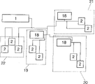
Fig. 6 represents to be used for the logical topology of the various headend equipments 18 in the corresponding communication system on electrical network.The use of a plurality of headend equipments 18 allows to create headend equipment group 18 and adds user 2, is positioned at away from the user instrument of main front end tool 1 and can communicates by letter so that may take independently to communicate by letter between described two instruments or reach (according to cable length or decay).
In order to make the communication of main headend equipment instrument 1 not disturb mutually with communicating by letter of headend equipment instrument 18, different frequencies and/or time are used in two communications.Can be used to be known as one " link " with a class frequency and the time of the system communication of this specification.In every group, time and frequency are reused, and just identical time and frequency are used in transmission by headend equipment group 18 and user 2 thereof, and feasible signal from a group may disturb the signal of other group or be disturbed by the signal of other group.
In a realization of the present invention, " link " can by use be used to transmit 1 to 5MHz frequency constitute, and another constitutes by transmitting 5 to 10MHz.All instruments all adopt " link " of one group of use or these class frequencys and therefore may interfere with each other.
Communicating by letter between main headend equipment instrument 1 and the user instrument 2 undertaken by one " link ", and the communication between headend equipment instrument 18 and the user thereof is undertaken by another " link ", thereby avoids two interference between the communication.
The headend equipment 18 of these groups is shared identical " link ", and just they use identical frequency and the time to send.Therefore, the signal in headend equipment 18 and the user instrument 2 thereof is disturbed by another headend equipment 18 and user 2 thereof, and vice versa.The topology of electrical network can be used to make the headend equipment 18 of a group and user 2 (according to cable length or decay) distance enough far, so that the signal that sends in (upstream and downstream) two channels can not produce high interference.
Since the existence of these interference groups, the reduction that in 18 groups of headend equipments and user's 2 thereof upstream and downstream channel, produces signal to noise ratio.
Native system is the form that allows 18 groups of each headend equipments wherein and user's 2 coexistences thereof about the novelty of this point.For this reason, we will be mainly based on control transmission power.
Fig. 7 represents the example of the physical connection between (on electric wire) two different instruments, its expression headend equipment instrument 18 and the position of user instrument 2 in four different buildings 19 to 22.
In order to take automatic gain control, suppose to have arrived a not headend equipment instrument 18 in its group by the signal that user instrument 2 sends, it will have to propagate a long distance and through wherein its point that will be connected with the headend equipment instrument 18 of its group on the network.This is to utilize the topology of power distribution network to realize easily.For example, headend equipment instrument 18 can be positioned on the electric input point of building, and user instrument 2 is in building, as shown in Figure 7.The group of headend equipment 18 and user's 2 thereof coexistence is based on such fact: all users 2 that append to a specific front-end equipment 18 always connect so that can arrive the not point of another headend equipment 18 in its group through this headend equipment 18 wherein.For this reason, we measure the decay between the headend equipment 18, and this can carry out automatically by transmission information between headend equipment instrument 18 and/or 1.As previously mentioned, this value is used to the user to adjust maximum transmission power.
In downstream channel, the signal in the adjacent headend equipment tool 18 can mix with the signal from the headend equipment in our group 18.This disturbs the noise introduced the additive white Gaussian noise type in system (this is owing to such fact: have about 1,000 distribution statisticses with the ofdm signal of the carrier wave of M-QAM modulation and be actually standard).The user receives (its headend equipment and adjacent headend equipment) signal.The signal of the headend equipment 18 of our group will be decayed pro rata with the distance from user instrument 2 to its headend equipment 18, and the signal of " interference " headend equipment 18 will and user instrument 2 and another headend equipment 18 between distance decay pro rata.If " interference " greater than the noise on the circuit, then the degradation of S/N will mainly disturb institute cause by this, so S/N will be poor between the signal power, just directly with two headend equipments 18 between the decay of existence proportional.
Fig. 8 represents that not on the same group the headend equipment 18 for downstream channel adds the interference between the user 2.
On the mathematics, from the signal that its headend equipment instrument 18 receives be by user 2:
P r=S 2-L u
S wherein 2Be the signal power that sends by headend equipment 18, L uIt is the decay that is mainly produced by (electric wire) distance that exists between headend equipment 18 and the user 2.On the other hand, (being sent) interference signal by the headend equipment instrument 18 of other group is:
P i=S 1-L-L u
Wherein, S 1Be the power of the signal that sends of the headend equipment 18 by other group, L is the decay between the headend equipment 18.Usually, this interference power is greater than the quantizing noise of user ADC receiver, so the S/N tolerance limit becomes:
S/N=P r-max(N ADC,P i)=P r-P i=S 2-L u-(S 1-L-L u)=S 2-S 1+L
All headend equipment instruments 18 all send (reciprocity is disturbed and maximization covers so that have) with maximum power, so the maximum of S/N will equal the decay (L) between the headend equipment instrument.
Under the situation of " link " more than two, the decay between the headend equipment 18 may be unequal, and this is because headend equipment 18 can be seen other group that has more high attenuation and may have bigger gain.In this case, main headend equipment instrument 1 will be responsible for utilizing control messages (the perhaps channel of other type control) to adjust gain.
About upstream channel, purpose be from another organize signal that another headend equipment 18 adds user 2 with power distribution network in the power level that is more or less the same of background noise arrive our group (its instrument just uses identical time and frequency from identical " link ").
If two power levels equate that then be created in the raising of the 3dB on the intrinsic noise level, this is considered to acceptable degradation in the upstream channel.
Therefore, user instrument 2 must be revised transmission gain and will do like this to be less than or equal to for this reason the performance number of headend equipment 18 detected circuit noises so that guarantee to arrive the signal of the headend equipment 18 of other group.Detection is to carry out in the headend equipment 18 of each group, and the user 2 of this group is used control messages (perhaps the channel of other type control) and notifies.Therefore, utilize the control in the closed loop to adjust.This is illustrated in Fig. 9, wherein shows the interference in the upstream channel.
User instrument 2 is with power S transmission signals in upstream channel.This signal attenuation ground arrives described group headend equipment 18 (decay L 1) and arrive with this value and add the decay that characterizes between the headend equipment 18 and arrive the headend equipment 18 (S-L of another group damply 1-L 2).This signal is considered to the noise for (reusing same frequency and time) other group, so the value of S is adjusted to revise the transmission of user instrument 2, so that S-L 1-L 2To become the intrinsic noise level on the circuit.
On the mathematics, power disturbance will become:
P i=S-L 1-L 2
And we can say N<P i(if it is greater than the noise that is caused by the other factors such as ADC).
In order to optimize the result, and because channel does not have the uniform response in frequency, so transmission gain must be by carrier wave ground change one by one.Because this can raise the cost greatly, so can use the average estimation that on frequency, obtains S/N than the carrier wave more generally of the carrier wave with less S/N value with big S/N value.
These operations are to carry out in corresponding to described group headend equipment instrument 18, and described group determines that each user's 2 of this group gain is should be enhanced, reduce or keep.Afterwards, it utilizes control channel (preferably utilizing control messages) that this information is sent to user 2.It uses the weighted value of S/N estimation and the preceding value of this estimation to carry out this decision.

Claims (22)

1. AGC (automatic gain control) system that is used for the digital OFDM multi-user transmission system on electrical network, wherein a plurality of user instruments and headend equipment instrument carry out two-way communication by described electrical network, has independent control for upstream channel from the user instrument to the headend equipment and the downstream channel from the headend equipment to the user instrument, the electrical network that wherein utilizes Frequency Division Duplexing (FDD) (FDD) and/or time division duplex (TDD) to carry out the upstream and downstream channel is divided, one of them signal is utilized OFDM modulation (it is multiplexing to utilize orthogonal frequency to carry out) and sends, result as this modulation, it is the signal with non-constant envelope, and comprise that amplifier acts on transmission and receiving gain, and under the situation of the various combinations that may use headend equipment and user instrument, reuse identical frequency and time, wherein utilize OFDMA/TDMA multiplexing (utilize orthogonal frequency to carry out multiplexing/utilize the time-division to carry out multiplexing) to insert the upstream and downstream channel, it is characterized in that:
-carrier processing corresponding transmitted signals one by one, so that before the time domain that transforms to the average power of wherein having fixed signal, the such frequency-selective channel of retrieved image electrical network is for the influence of signal in advance,
-in reception, signal in the carrier processing frequency domain one by one, wherein the compensator of the influence of block of channels is carried out the scaling of the element correction of received signal and signal in frequency, utilize the signal that a floating point representation compensated and the fixing bit number of mantissa, thereby obtain a maximal accuracy or the signal to noise ratio determined by the carrier wave definition, therefore the memory of the compensating elements of memory channel influence can be reduced, thereby reduced the complexity in the frequency-domain operations by the fixing bit number of mantissa, the more great dynamic range of processing signals in reception, and the signal that will enter ADC is amplified to maximum, and can not overflow for producing in the frequency processing piece in front
-control is from the through-put power of various tool, so that received with identical level and can be used the seldom A/D converter of bit for various users' power,
-control transmission power can not disturb at other group headend equipment that uses identical frequency and time and user's generation in service so that guarantee the signal that is sent to headend equipment by the user;
Utilize these essential characteristics, AGC (automatic gain control) system of the present invention can:
-reach maximum transfer capacity,
-reach user's maximum quantity by frequency reuse and time,
-under the situation that does not worsen signal to noise ratio or transmission capacity, admit from according to cable length or decay nearby or the signal of remote subscriber,
-avoided causing in the system authority of transmission capacity loss on the generation of overflowing,
-avoided by Legal Regulation or produce and the use of the frequency of the interference of other communication system,
-introduced the maximum average power in the frequency range that can be used for communicating by letter, and
-minimize the needed bit number of mould/number conversion in the reception.
2. the AGC (automatic gain control) system that is used for the digital OFDM multi-user transmission system on electrical network according to claim 1, it is characterized in that for the automatic gain in downstream control both adjusted the gain in the transmitter of headend equipment instrument, also adjust the gain in the receiver of user instrument, so that do not produce in the system converter under the situation of overflowing, maximum average power in the scope that introducing can be used for communicating by letter, purpose are maximizes transmission capacity.
3. the AGC (automatic gain control) system that is used for the digital OFDM multi-user transmission system on electrical network according to claim 2, it is characterized in that if produce in the ADC receiver on quantity definite restriction of overflowing above one, then the control of the automatic gain in downstream reduces the gain in the receiver user, this is that this can cause the deterioration in the transmission capacity because these overflows go out to produce reducing of S/N ratio.
4. the AGC (automatic gain control) system that is used for the digital OFDM multi-user transmission system on electrical network according to claim 2, it is characterized in that if in the ADC receiver, do not overflowing in the generation during the time window of determining, then the control of the automatic gain in the downstream increases the gain in the receiver user, can not limit S/N so that quantizing noise is compared with the circuit noise of amplification.
5. according to the described AGC (automatic gain control) system that is used for the digital OFDM multi-user transmission system on electrical network of claim 2 to 4, one of respective algorithms who it is characterized in that being used for the automatic gain control of downstream channel may realize being based on picture and overflow on the ADC receiver that produces during the time window of determining, the control of the each side that saturated quantity and equalization weights are such, if so that in the time window on the quantity of overflowing greater than certain threshold value, then the gain of receiver is reduced, do not show that signal can increase power and overflows on can not producing if surpass simultaneously this threshold value and equalization weights for whole window, then the gain in the receiver is increased; And if in these situations any one all do not have to occur, then system's gain of being considered to be in an optimizing level and the respective amplifier is not modified; The system of surveillance gain value always is used, so that the cycle checking of avoiding producing the raising of vibrating and gaining in gain in reception can not improve signal to noise ratio.
6. the AGC (automatic gain control) system that is used for the digital OFDM multi-user transmission system on electrical network according to claim 1, it is characterized in that in upstream channel, the gain in the headend equipment receiver had both been adjusted in automatic gain control, also adjust the gain in user's transmitter, before gain in the transmitter in carrying out user instrument is adjusted, be adjusted at the gain in the headend equipment instrument in the reception, purpose be avoid since on overflow the deterioration of the S/N that is caused and the quantizing noise of the ADC in the headend equipment instrument.
7. the AGC (automatic gain control) system that is used for the digital OFDM multi-user transmission system on electrical network according to claim 6, it is characterized in that it is to be used as the function of the noise on the circuit and fixing that for the automatic gain of upstream channel control is included in the reception of headend equipment instrument fixed gain, so that the headend equipment instrument is measured the power of noise and is adjusted gain, purpose is that the quantizing noise of ADC is not compared with the circuit noise of amplification and can be limited S/N, and makes to use to have the transducer that reduces number of bits.
8. the AGC (automatic gain control) system that is used for the digital OFDM multi-user transmission system on electrical network according to claim 7, it is characterized in that because when not having user instrument when sending, headend equipment uses DFT (discrete Fourier transform (DFT)) on the signal that receives, described noise testing takes place, and it can be by increasing the gain in receiving and the outlet of a described DFT definite threshold when not having user instrument to send being come the estimation of line noise.
9. the AGC (automatic gain control) system that is used for the digital OFDM multi-user transmission system on electrical network according to claim 7, the rub-out signal that provides from the reception equalizer headend equipment and from sending and the known gain of reception amplifier begins to carry out described noise testing is provided when some users are sending.
10. the AGC (automatic gain control) system that is used for the digital OFDM multi-user transmission system on electrical network according to claim 6, it is characterized in that for upstream channel, the gain controlling of the transmit amplifier in user instrument appears in open loop and/or the closed loop, so that maximizes transmission capacity and minimizing needed bit number of the conversion on whole range of signal in ADC:
-in open loop control,, should be estimated by the quantity of power that upstream channel sends by the power that in downstream channel, receives;
-in closed-loop control, the headend equipment instrument is measured its power from the user instrument received signal and reception, and whether it overflows in the generation in corresponding ADC; And measure beginning preferably by transmitting control message to show that to user instrument it should increase or reduce to send gain amplifier from this.
11., it is characterized in that of agc algorithm in upstream channel may realize comprising according to the described AGC (automatic gain control) system that is used for the digital OFDM multi-user transmission system on electrical network of claim 7 to 10:
-at first, if in the estimated time window on the threshold value that is allowed to greater than a maximum of the quantity of overflowing and this value, then gain is lowered;
-still reduce receiving gain in the headend equipment instrument in order to determine to reduce transmission gain by user instrument, the information that is provided by the weighting equalizer is used for distinguishing that to overflow be because the information signal that the user sends is produced, still produce owing to circuit noise, last overflowing is because under the situation that information signal produced that the user sends, the headend equipment instrument shows to user instrument will reduce transmission level, last overflowing is owing under the situation that circuit noise produced, the gain in will being reduced to receive by the headend equipment instrument;
-gain improves, and this has only when the reason that does not reduce to gain exists and just is used, and appears in the user instrument so that this gain only improves can not causing overflowing Shi Caihui;
-situation whatsoever, the system that the surveillance gain value is avoided vibrating always is used;
-by in enough separated definite time, communication line is monitored so that it is correct checking the fixed value of the gain in reception, and the impulsive noise on the network causes a unsuitable adjustment, and if necessary, then revises this value.
12. the AGC (automatic gain control) system that is used for the digital OFDM multi-user transmission system on electrical network according to claim 1, it is characterized in that in order to optimize gain controlling, use the carrier processing one by one of corresponding transmitted signals to come the influence of compensate for channel on signal in advance, by being increased in by the power in the carrier wave that suffers more decay in the channel transmission and being reduced in the channel by the power in the less carrier wave that sends damply, make to keep average transmitting power and transmission capacity to be increased, do not overflow and can in the signal processing in time or the mould/number conversion, not produce.
13. the AGC (automatic gain control) system that is used for the digital OFDM multi-user transmission system on electrical network according to claim 12, it is characterized in that in the carrier processing one by one in transmission, there is a decay gradually, it comprises eliminates the carrier wave that its frequency location conforms to following frequency: it uses by the frequency of Legal Regulation, the frequency of disturbing other communication equipment, the intermediate frequency of using in TV and other electronic equipment, the amateurish frequency of radio etc., and wherein the selection of carrier wave is to dispose in real time at each communication needs constantly according to system.
14. the AGC (automatic gain control) system that is used for the digital OFDM multi-user transmission system on electrical network according to claim 1, it is characterized in that in order to optimize gain controlling, the carrier processing one by one of corresponding signal is used in frequency domain once in reception, the compensator block that comprises the influence of compensate for channel on the signal that receives, value according to level of estimating for the signal of the reception in each carrier wave and the frequency corrector element that uses on this signal is come this signal of proportional zoom, so that may be only to the reception mantissa in the floating-point of the signal that receives, mantissa and index work, and the last bit number that fixes this mantissa according to the maximal accuracy or the signal to noise ratio of carrier wave; Purpose is to use considerably less bit number to represent to have the signal of great dynamic range, just has very high or very lower powered signal, thereby reduce to be used for to store the size of memory of the operation of frequency domain, so that wherein have the bit that reduces quantity, and signal is amplified to maximum in porch to mould/number conversion, and can in frequency domain, in each piece, not overflow in the generation before the carrier processing signal one by one, reception has the carrier wave than high attenuation that quantizing noise limited that is not subjected to A/D converter in reception being subjected to the noise on the circuit on the signal to noise ratio, and receive simultaneously less by Line Attenuation and before conversion the carrier wave that is exaggerated, do not overflow and can by scaling easily the time, not produce, so that handle them for having the bit number in each operation identical than the carrier wave of high attenuation by the frequency chunks utilization.
15. the AGC (automatic gain control) system that is used for the digital OFDM multi-user transmission system on electrical network according to claim 14, it is characterized in that in aforementioned proportion convergent-divergent process, when the signal times that receives during with the expression index of the floating point representation of equalization weights, picked up signal mantissa, if and the data that wherein send are pointed to other user and in all carrier waves, when the data that send are pointed to our user, the equalizing training stage of described index in the grid carrier wave upgraded oneself, so that reduce owing to influence the possibility of the error of graduation that a plurality of impulsive noise caused of the communication on the electrical network.
16. according to the described AGC (automatic gain control) system that is used for the digital OFDM multi-user transmission system on electrical network of claim 1 to 7, it is characterized in that using the user's who respectively organizes headend equipment and communicate by letter with the former of same frequency and the frequency reuse of time and time the realization of coexistence is by controlling the transmission gain in these instruments, and the device that receives of the control that has been described in front the claim, the judgement so that various headend equipment instrument mutual communication coexists.
17. according to the described AGC (automatic gain control) system that is used for the digital OFDM multi-user transmission system on electrical network of claim 1 to 7, it is characterized in that using the user's who respectively organizes headend equipment and communicate by letter with the former of identical frequency and the frequency reuse of time and time the realization of coexistence is by controlling the transmission gain in these instruments, and the device of control receiving gain is to realize by the described device of the claim of front, so that there is a main headend equipment instrument, its uses different frequency and/or the time is used for and its telex network and being responsible for guarantees to reuse coexistence between each group instrument of same frequency and time, and it can be communicated by letter with every group headend equipment.
18. according to the described AGC (automatic gain control) system that is used for the digital OFDM multi-user transmission system on electrical network of claim 16 to 17, it is characterized in that when each group is reused the headend equipment of identical frequency and time and user, in order to optimize the gain controlling result, send gain by carrier wave ground modification one by one, this is because this means the increase of cost, consider that carrier wave that the carrier wave ratio with big signal to noise ratio has a less signal to noise ratio comes the average signal-to-noise ratio in the estimated frequency, and this result is used to reach the modification that sends in the gain.
19. according to the described AGC (automatic gain control) system that is used for the digital OFDM multi-user transmission system on electrical network of claim 16 to 18, the coexistence of respectively organizing headend equipment and user instrument that the frequency that it is characterized in that using same range as and time are used to communicate by letter is possible, this be because:
Power control in-the corresponding signal dispensing device in these two communication channels of upstream and downstream;
-network topology was wherein at first passed through headend equipment instrument corresponding to their group from the signal of all user instruments before arriving the instrument of forming another group; And
-by reusing transmission information between the headend equipment instrument of same frequency and time or measuring decay between these headend equipment instruments by communicating by letter, so that this measurement is used to adjust the maximum transmit power that may be used for user instrument with a main headend equipment instrument.
20. according to the described AGC (automatic gain control) system that is used for the digital OFDM multi-user transmission system on electrical network of claim 16 to 18, it is characterized in that in downstream channel, all headend equipment instruments send by the maximum power of the communication system of power grids may being used for, so that the maximum for the noise in user's receiver (S/N) ratio will be limited by the decay between the headend equipment instrument of frequency of reusing same range as and time, if there is simultaneously one to use the frequency of another scope and/or the main headend equipment of time, then it will be this main headend equipment instrument of being responsible for utilizing channel control and preferably utilizing control messages to be adjusted at the different gains that needs in the various headend equipment instruments.
21. according to the described AGC (automatic gain control) system that is used for the digital OFDM multi-user transmission system on electrical network of claim 16 to 18, it is characterized in that coexistence for the instrument of respectively organizing that guarantees in the upstream communication channel, to reuse same frequency and time, transmission in user instrument gain is adjusted, so that arrive the headend equipment of another group and may disturb the level of signal power of this group and the noise level on the circuit to be more or less the same.
22. the AGC (automatic gain control) system that is used for the digital OFDM multi-user transmission system on electrical network according to claim 21, it is characterized in that in the upstream communication channel, the headend equipment tool detection is should improve gain or reduce gain from power and the decision that its one of user arrives, and preferably utilizes control messages this information to be sent to the user instrument that relates to subsequently; Value, the preceding value of this estimation and the estimation of noise of the estimation of headend equipment by using the signal to noise ratio be considered in frequency determine accordingly.
CNB028101170A 2001-05-17 2002-05-17 Automatic gain control system for multi-user OFDM digital transmission system using the electric grid Expired - Lifetime CN1280998C (en)

Applications Claiming Priority (2)

Application Number Priority Date Filing Date Title
ES200101121A ES2187274B1 (en) 2001-05-17 2001-05-17 AUTOMATIC GAIN CONTROL SYSTEM FOR MULTI USER DIGITAL TRANSMISSION SYSTEM ON ELECTRICAL NETWORK.
ESP200101121 2001-05-17

Publications (2)

Publication Number Publication Date
CN1509525A true CN1509525A (en) 2004-06-30
CN1280998C CN1280998C (en) 2006-10-18

Family

ID=8497739

Family Applications (1)

Application Number Title Priority Date Filing Date
CNB028101170A Expired - Lifetime CN1280998C (en) 2001-05-17 2002-05-17 Automatic gain control system for multi-user OFDM digital transmission system using the electric grid

Country Status (17)

Country Link
US (1) US7545733B2 (en)
EP (1) EP1394960B1 (en)
JP (1) JP4143416B2 (en)
KR (1) KR100724500B1 (en)
CN (1) CN1280998C (en)
AT (1) ATE365400T1 (en)
AU (1) AU2002311177B2 (en)
BR (1) BR0209902A (en)
CA (1) CA2447256A1 (en)
DE (1) DE60220789T2 (en)
EA (1) EA005656B1 (en)
ES (2) ES2187274B1 (en)
HK (1) HK1061320A1 (en)
IL (2) IL158720A0 (en)
MX (1) MXPA03010388A (en)
PT (1) PT1394960E (en)
WO (1) WO2002093775A1 (en)

Cited By (3)

* Cited by examiner, † Cited by third party
Publication number Priority date Publication date Assignee Title
CN106549690A (en) * 2016-11-05 2017-03-29 北京晓程科技股份有限公司 Power carrier communication system auto gain control method and device
CN110392421A (en) * 2018-04-18 2019-10-29 电信科学技术研究院有限公司 A kind of signal processing method and equipment based on AGC
CN112640300A (en) * 2018-06-27 2021-04-09 北欧半导体公司 Automatic gain control

Families Citing this family (28)

* Cited by examiner, † Cited by third party
Publication number Priority date Publication date Assignee Title
GB0116493D0 (en) 2001-07-06 2001-08-29 Koninkl Philips Electronics Nv Receiver having an adaptive filter and method of optimising the filter
ES2212744B2 (en) 2003-01-10 2005-03-16 Diseño De Sistemas En Silicio, S.A. SYNCHRONIZATION PROCEDURE IN THE DOMAIN OF TIME AND FREQUENCY OF MULTIPLE EQUIPMENT IN A TRANSMISSION SYSTEM WITH OFDM MODULATION.
US11152971B2 (en) * 2004-02-02 2021-10-19 Charles Abraham Frequency modulated OFDM over various communication media
EP1643658A1 (en) 2004-10-04 2006-04-05 Sony Deutschland GmbH Power line communication method
KR100623485B1 (en) * 2004-12-21 2006-09-13 한국전자통신연구원 A receiving apparatus of orthogonal frequency division multiplex system and a demodulation method thereof
JP4602073B2 (en) * 2004-12-28 2010-12-22 パナソニック株式会社 Communication apparatus and communication method
US7653368B2 (en) * 2006-06-14 2010-01-26 Intel Corporation Radio receiver and a method thereof
JP2008153913A (en) * 2006-12-18 2008-07-03 Sharp Corp Digital demodulation device, digital receiver, control method of digital demodulation device, control program of digital demodulation device and storage medium storing the control program
KR101468490B1 (en) 2007-05-02 2014-12-10 삼성전자주식회사 Method and apparatus for qualitatively transmitting and receiving a set of control channels in a wireless communication system
SI2023501T1 (en) * 2007-08-07 2012-09-28 Abb Technology Ag Data transmission method
JP2009099084A (en) * 2007-10-19 2009-05-07 Kyocera Corp Conversion device
CN101471723B (en) * 2007-12-26 2012-09-05 北京朗波芯微技术有限公司 Bidirectional dynamic amplification method and apparatus for TDD system
US8165172B2 (en) * 2008-06-06 2012-04-24 Maxim Integrated Products, Inc. Robust wideband symbol and frame synchronizer for power-line communication
US8284825B2 (en) * 2008-06-06 2012-10-09 Maxim Integrated Products, Inc. Blind channel quality estimator
US8315341B2 (en) * 2008-06-06 2012-11-20 Maxim Integrated Products, Inc. Soft repetition code combiner using channel state information
US8276025B2 (en) * 2008-06-06 2012-09-25 Maxim Integrated Products, Inc. Block interleaving scheme with configurable size to achieve time and frequency diversity
US8139614B2 (en) * 2008-06-06 2012-03-20 Maxim Integrated Products, Inc. Robust narrowband symbol and frame synchronizer for power-line communication
US8149967B2 (en) * 2008-06-06 2012-04-03 Maxim Integrated Products, Inc. Combined dual feed-forward and feedback analog and digital automatic gain control for broadband communication
US8315152B2 (en) 2008-06-06 2012-11-20 Maxim Integrated Products, Inc. System and method for applying multi-tone OFDM based communications within a prescribed frequency range
US8472576B2 (en) 2008-06-06 2013-06-25 Maxim Integrated Products, Inc. Jammer canceller for power-line communication
US8320233B2 (en) 2009-06-12 2012-11-27 Maxim Integrated Products, Inc. Transmitter and method for applying multi-tone OFDM based communications within a lower frequency range
US8824344B2 (en) 2009-09-09 2014-09-02 Nec Corporation Time division duplex communication apparatus and reception interference preventing method thereof
CN102870475B (en) * 2010-03-12 2016-12-07 日升微器件公司 The communication of power-efficient
FR2971107B1 (en) * 2011-01-27 2015-04-03 Spidcom Technologies METHOD AND DEVICE FOR TRANSMITTING A SIGNAL USING A TRANSMISSION POWER MASK
PL2744117T3 (en) * 2012-12-13 2017-09-29 Deutsche Telekom Ag Method for reducing interference in a communication network
CN108541055B (en) * 2018-03-02 2019-09-20 珠海格力电器股份有限公司 Power adjustment method and device and power adjustment method based on power line carrier
CN112737637B (en) * 2020-12-24 2022-11-15 阳光电源股份有限公司 Power carrier communication crosstalk optimization method and photovoltaic system
DE102022111224A1 (en) * 2022-05-05 2023-11-09 Bayerische Motoren Werke Aktiengesellschaft Wired communication system and method for determining a transmission signal strength of a plurality of transceivers

Family Cites Families (21)

* Cited by examiner, † Cited by third party
Publication number Priority date Publication date Assignee Title
US5448593A (en) * 1984-03-06 1995-09-05 Cyplex Corporation Frequency hopping time-diversity communications systems and transceivers for local area networks
JPH03274818A (en) * 1990-03-23 1991-12-05 Matsushita Electric Ind Co Ltd Automatic equalizer circuit
JPH07297748A (en) * 1994-04-26 1995-11-10 Clarion Co Ltd Transmission-reception system
US6058104A (en) * 1994-06-17 2000-05-02 Home Wireless Networks, Inc. Communications webs for PSTN subscribers
US6334219B1 (en) * 1994-09-26 2001-12-25 Adc Telecommunications Inc. Channel selection for a hybrid fiber coax network
US5765097A (en) * 1996-05-20 1998-06-09 At & T Corp Shared hybrid fiber-coax network having reduced ingress noise in the upstream channel transmitted via a repeater
JPH10150426A (en) * 1996-11-19 1998-06-02 Toshiba Corp Data generator for fm multiplexing processing
JP3667960B2 (en) * 1997-11-04 2005-07-06 日本放送協会 OFDM transmission method, transmitter, and receiver
JP3217307B2 (en) * 1997-11-18 2001-10-09 沖電気工業株式会社 Wireless transmission device
JP2920131B1 (en) * 1998-01-28 1999-07-19 株式会社次世代デジタルテレビジョン放送システム研究所 OFDM signal transmission device
JPH11266199A (en) * 1998-03-17 1999-09-28 Matsushita Electric Ind Co Ltd Radio communication base station device
JP3572933B2 (en) * 1998-03-31 2004-10-06 Kddi株式会社 Mobile communication system
JP3024755B2 (en) * 1998-06-24 2000-03-21 日本電気株式会社 AGC circuit and control method therefor
ITMI981699A1 (en) * 1998-07-23 2000-01-23 Alsthom Cge Alcatel METHOD AND DEVICE FOR BIDIRECTIONAL DATA EXCHANGE LONG LOW AND MEDIUM VOLTAGE ELECTRICAL LINES
JP4287536B2 (en) * 1998-11-06 2009-07-01 パナソニック株式会社 OFDM transmitter / receiver and OFDM transmitter / receiver method
JP2000269925A (en) * 1999-03-17 2000-09-29 Mitsubishi Electric Corp Device and method for data communication
JP3191802B2 (en) * 1999-06-17 2001-07-23 三菱電機株式会社 Communication device and communication method
US6363127B1 (en) * 1999-06-23 2002-03-26 At&T Wireless Services, Inc. Automatic gain control methods and apparatus suitable for use in OFDM receivers
US7298691B1 (en) * 2000-08-04 2007-11-20 Intellon Corporation Method and protocol to adapt each unique connection in a multi-node network to a maximum data rate
US7295518B1 (en) * 2001-08-30 2007-11-13 Entropic Communications Inc. Broadband network for coaxial cable using multi-carrier modulation
US7002899B2 (en) * 2001-10-09 2006-02-21 Ati Technologies Inc. Method and apparatus to improve SCDMA headroom

Cited By (3)

* Cited by examiner, † Cited by third party
Publication number Priority date Publication date Assignee Title
CN106549690A (en) * 2016-11-05 2017-03-29 北京晓程科技股份有限公司 Power carrier communication system auto gain control method and device
CN110392421A (en) * 2018-04-18 2019-10-29 电信科学技术研究院有限公司 A kind of signal processing method and equipment based on AGC
CN112640300A (en) * 2018-06-27 2021-04-09 北欧半导体公司 Automatic gain control

Also Published As

Publication number Publication date
AU2002311177B2 (en) 2007-04-26
EP1394960A1 (en) 2004-03-03
ATE365400T1 (en) 2007-07-15
US7545733B2 (en) 2009-06-09
IL158720A0 (en) 2004-05-12
DE60220789T2 (en) 2008-03-06
ES2187274B1 (en) 2004-08-16
ES2289108T3 (en) 2008-02-01
ES2187274A1 (en) 2003-05-16
BR0209902A (en) 2004-07-27
DE60220789D1 (en) 2007-08-02
KR100724500B1 (en) 2007-06-04
PT1394960E (en) 2007-10-02
EP1394960B1 (en) 2007-06-20
MXPA03010388A (en) 2004-03-16
EA005656B1 (en) 2005-04-28
EA200301168A1 (en) 2004-08-26
HK1061320A1 (en) 2004-09-10
WO2002093775A1 (en) 2002-11-21
US20040120249A1 (en) 2004-06-24
JP2004529577A (en) 2004-09-24
IL158720A (en) 2008-11-03
KR20040014523A (en) 2004-02-14
JP4143416B2 (en) 2008-09-03
CA2447256A1 (en) 2002-11-21
CN1280998C (en) 2006-10-18

Similar Documents

Publication Publication Date Title
CN1280998C (en) Automatic gain control system for multi-user OFDM digital transmission system using the electric grid
CN1299439C (en) Communication optimisation method for multi-user OFDM digital transmission system using electrical network
CN1117459C (en) Method and apparatus for superframe bit allocation in discrete multitone system
CN104143998B (en) The method and apparatus reducing feedback overhead
CN1036884C (en) Method and device for adjusting transmission power in wireless system
RU2415515C2 (en) Managing power for wireless communication network
JP4105133B2 (en) Scheduling method and apparatus for multiple users in a mobile communication system using multiple transmit / receive antennas
EP1895680B1 (en) Apparatus and method for transmitting/receiving data in a multi-antenna system, and system using the same
CN1148015C (en) Transmit diversity method and system
CN1116754C (en) Digital radio frequency interference canceller
CN1658532A (en) Wireless relay system, wireless relay apparatus, and wireless relay method
CN1613198A (en) Method and apparatus for adaptive QoS-based joint rate and power control algorithm in multi-rate wireless systems
WO2016122252A1 (en) System and method for link adaptation for low cost user equipments
CN1489833A (en) Digital point-to-multiponit data transmission system on electric network
CN1864382A (en) Apparatus and method of multiple antenna receiver combining of high data rate wideband packetized wireless communication signals
CN1643866A (en) A multiple channel wireless receiver
CN1790943A (en) Method and system for transmissing information in communication system
WO2010101443A2 (en) Method and apparatus for power control in a wireless communication system
CN1229553A (en) Digital radio frequency interference canceller
EP3821651A1 (en) Method and apparatus for reducing energy consumption of terminal in wireless communication system
WO2022010231A1 (en) Method and apparatus for uplink transmit beam selection procedures in a wireless communication system
CN1716926A (en) Automatically control the method and apparatus of the step-length of lowest mean square type equalizer
CN1701542A (en) Optical transmission system with gain control for reducing spurious components
US7418030B2 (en) Flexible initialization method for DSL communication systems
WO2021006569A1 (en) Apparatus and method for controlling gain of received signal in wireless communication system

Legal Events

Date Code Title Description
C06 Publication
PB01 Publication
C10 Entry into substantive examination
SE01 Entry into force of request for substantive examination
C14 Grant of patent or utility model
GR01 Patent grant
ASS Succession or assignment of patent right

Owner name: MARVELL SPAIN CO., LTD.

Free format text: FORMER OWNER: DISE DE SISTEMS EN SILICIO S.A.

Effective date: 20110402

C41 Transfer of patent application or patent right or utility model
COR Change of bibliographic data

Free format text: CORRECT: ADDRESS; FROM: VALENCIA, SPAIN TO: MADRID, SPAIN

TR01 Transfer of patent right

Effective date of registration: 20110402

Address after: Madrid

Patentee after: Marvell Hispania, S.L.

Address before: Valencia

Patentee before: Diseno Sistemas Silicio SA

CX01 Expiry of patent term

Granted publication date: 20061018