Injection (mo(u)lding) machine with mould platen of the mold clamping force that is used for evenly distributing
Technical field
The present invention relates to a kind of structure that is used for movable platen (a movable platen), this movable platen is used for supporting at injection (mo(u)lding) machine the part of injection molding.Especially, the present invention relates to a kind of moveable die support platen that improves rigidity that has, this platen is carried on the injection (mo(u)lding) machine underframe slidably.
Background technology
In general, the machinery that is used for the injection molded goods includes a pair of stationary platen, and this is separated from each other stationary platen, and is connected with each other by four parallel draw bars usually, and the axis of described parallel draw bar is oriented to limit a rectangular array.Keep static one of in the described stationary platen, and be suitable for supporting the part of two or many injection moldings, when assembled or when being joined together, described two or many injection moldings limit a die cavity, and this die cavity is corresponding to the outline of required mechanograph.Movable platen is carried on the pull bar between the described stationary platen slidably, and be suitable for carrying a cooperation part on the described mould, when shifting to the stationary platen that carries mould part with this movable platen of box lunch, two mould parts come in contact, and limit a die cavity that is used to produce required goods between them.
Movable platen is a rectangular plate-like members normally, and includes four borings that are positioned at the respective corners place, all extends through a pull bar in each boring.A movable platen actuating system is placed between the stationary platen and movable platen that does not carry mould, with so that movable platen along pull bar towards or deviate from described mould platen and move, and when described mould partly closes up together, movable platen is securely fixed on the suitable position, to prevent that described mould separates in the die cavity along with melted material under high pressure is injected into.
Platen in the injection (mo(u)lding) machine normally is processed to the parts (block) as shown in following patent: the U.S. Patent No. 5188850 that licenses to Hirata etc.; License to the U.S. Patent No. 5066217 of Fukuzawa etc.; License to the U.S. Patent No. 5110283 of Bluml etc.; License to the U.S. Patent No. 5123834 of Joyner; License to the U.S. Patent No. 5162782 of Yoshioka; License to the U.S. Patent No. 5192557 of Hirata etc.; License to the U.S. Patent No. 5593711 of Glaesener; And the U.S. Patent No. 5776402 that licenses to Glaesener.In each of these patents, the mould platen is the parts that are processed to have the rectangular side of cardinal principle basically, in described rectangle sides upper support a half mould (a mold half) is arranged.In closing up in the process of half mould, can on the die mounting surface of platen, produce a power.As following this parts shape platen usually, die mounting surface can deform with being recessed, and the upper and lower edge that forces described side is towards the power that is about to apply, and forces platen to bend, and produces stretching action across the trailing flank of mould platen.Finally, under the effect of chucking power, separate at the middle part of platen, cause producing a gap between half mould, and in some cases, the formation of burr (flash) is byproduct.
The U.S. Patent No. 4615857 that licenses to Baird discloses a kind of containment device and method that is used for reducing in the mold work process burr.According to this equipment, it is said that the injection of plastics and transfer moulding can carry out in the mode of obvious elimination burr.Wherein, under clamping cap (mold press) is in the condition of clamp position, the deflection of clamping cap is measured.By support post and pull bar are configured, thereby make them be used as the power that the independent spring that is resisted against on the die surface and response are produced when mould is in clamp position, the supporting construction of mould is configured to apply equal power to die surface.In order to learn the actual flexure amount of clamping cap, need calculate the spring constant and the length of described support post and pull bar, and on mould, apply a uniform pressure in the process in closing up of pressing plate thus.
Therefore, in order to compensate the bending phenomenon of platen, need measure the deflection degree of mould platen in the mould involution process, and a function as the lateral attitude on a platen or two platens is regulated the compressibility of the mould installing component in the described equipment, thereby the die joint to mould applies a constant power, and need not to consider the lateral attitude on die joint.The power that is provided by this installing component is provided for the hardness of described installing component and length, and is determined that according to predetermined formula and predetermined platen deflection described predetermined formula depends on the position of described installing component on platen.Although Baird compensates bending phenomenon, utilize this method and apparatus to realize that this point is very complicated, the certain force for being about to utilize particular mold to produce needs special-purpose structural design.Therefore, fail to realize the consistent design that is suitable for.
Accompanying drawing 5a and 5b disclose a kind of molded platen of prior art, and the shape of this molded platen is different slightly with those parts shape platens of discussing in institute's referenced patents.As shown in the accompanying drawing 5a, this mould platen profile (profile) includes the opening of several break-through, an antetheca and a rear wall.As shown in the accompanying drawing 5b, be extended with a plurality of groovings and rib towards rear wall, described rear wall can have a surface area less than the platen antetheca.Described platen also includes and is positioned at the boring that its each corner is used for ccontaining pull bar, and described pull bar is used for closing up process at mould and bears directed force F c between the platen.As shown, each root pull bar all carries a resistance FR.A plurality of groovings and rib are set to reduce the weight of platen.That is to say, close up in the process that as in simply supported beam, the die mounting surface of front is compressed, and rear wall is stretched at mould.As shown by dotted line among the accompanying drawing 5a and arrow, pull bar is pullled to the inside, and deform and come motion to be consistent, cause die surface in molding process, to bend thus and be the indent state, be similar to the platen in the aforementioned patent with platen surface.Therefore, although the design of mould platen has been shown among accompanying drawing 5a and the 5b, the buckling phenomenon of die surface can't be compensated, and still can produce burr.Because the both sides of platen all bend, so the support that is formed by pull bar also can bend around the corner, cause rob support to be subjected to uneven load effect.This will cause pull bar to bend, and too high stress is concentrated and can be caused taking place prematurely fatigue rupture.Arrow C shows pull bar and how to bend in the matched moulds process.
In order to make this situation more complicated, designed a kind of mould platen shown in accompanying drawing 5a and 5b in recent years, this mould platen can not come in contact with described many pull bars.On the contrary, this platen only is supported on the underframe of injection (mo(u)lding) machine, and in the matched moulds process, only has anchor clamps itself to support movable platen.As in the present invention (referring to accompanying drawing 4), platen is provided with bigger perforation, extends on the length direction of injection (mo(u)lding) machine to allow pull bar, and only is connected on the end platen that does not move.Because need not when movable platen is taken out from injection (mo(u)lding) machine described pull bar is removed, therefore this structure allows to dismantle apace and re-assembly, thereby is superior compared with prior art.But, apply uniform pressure across the surface of movable platen and can become and more become a problem as the result of this structure.The supernumerary structure rigidity that does not have pull bar, deflection can freely take place in movable platen around the corner, does not wish the burr that exist thereby can produce on final mechanograph in those zones on the mould.
Therefore, desirable is to have a kind of like this injection (mo(u)lding) machine, this injection (mo(u)lding) machine has a platen simple in structure and weight is lighter, this platen includes the device that is used for closing up at mould or pressing plate process compensation platen deflection, and can eliminate in injection-molded process basically and form burr.
Summary of the invention
Main purpose of the present invention is to provide a kind of injection (mo(u)lding) machine with a mould platen, and described mould platen is designed to obtain smooth and parallel substantially die mounting surface in the matched moulds process.
Another object of the present invention is to provide a kind of mould carrying platen of structure optimization, and this platen is particularly suitable for use in movable platen and is not connected in the injection (mo(u)lding) machine on the pull bar.
A further object of the present invention is to provide the lighter mould of a kind of weight to carry platen, this platen can provide smooth and parallel substantially die mounting surface in the matched moulds process, for a given injection (mo(u)lding) machine, required clamp pressure is less.
Another purpose of the present invention is to provide a kind of injection (mo(u)lding) machine, and this injection (mo(u)lding) machine has a structure optimization and the lighter platen of weight, is convenient to carry out quickly the cycle operation of mould, improves the output of a given injection (mo(u)lding) machine thus.
A further object of the invention is to provide a kind of injection (mo(u)lding) machine with a platen, because the weight saving of described movable platen, so the energy that each working cycles consumed of injection (mo(u)lding) machine is less.
Aforementioned purpose realizes by the injection (mo(u)lding) machine among the present invention.This injection (mo(u)lding) machine comprises: the stationary platen with one first half mould; At least one has the movable platen of one second half mould, and described second half mould is used for forming a mould with first half mould; Be used for the device of described movable platen being guided with respect to described stationary platen; And be used for molten resin is expelled to device in the described mould.For in the described platen at least one, a rear surface is placed in the middle part of this platen, is used to be connected to one such as the such pressure source of hydraulic cylinder.A front surface is parallel and spaced apart with described rear surface, is used to carry a half mould, and structural walls is from the periphery projection backward of this front surface.A plurality of isolated ribs extend to front surface from described rear surface, and these ribs are attached on the described structural walls with a kind of pattern rigidity of structurally optimizing.Also be provided with the device that is used for equably chucking power being passed to from the middle part of described rear surface front surface, in order to alleviate the local buckling of die surface.
Details of the present invention is illustrated in the following description and the drawings, and wherein, identical Reference numeral is used to describe identical member.
Description of drawings
Accompanying drawing 1 is a side elevation according to representative injection (mo(u)lding) machine of the present invention;
Accompanying drawing 2 is the cross-sectional side views according to platen of the present invention, shows a uniform involution pressure P;
Accompanying drawing 3a is the rearview such as axle such as grade of the platen after improving according to the present invention;
Accompanying drawing 3b is the front view such as axle such as grade of the platen after improving according to the present invention;
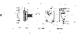
Accompanying drawing 4 is back elevational view of the platen after improving according to the present invention;
Accompanying drawing 5a and 5b are front views according to the platen of prior art.
The specific embodiment
With reference to accompanying drawing 1, show an injection (mo(u)lding) machine 11 substantially, this injection (mo(u)lding) machine 11 has used one at least according to movable platen 10 of the present invention.Anchor clamps 20 are connected in the middle part of the rear surface 14 of movable platen 10 by rigidity, and these anchor clamps 20 can be with platen open and close (arrow A) under the effect of a hydraulic cylinder 30.Movable platen 10 straddles on the guide rail 40 that is connected on the injection (mo(u)lding) machine underframe 38.Many pull bars 32 extend along the length direction of injection (mo(u)lding) machine 11, and are connected respectively on the isolated first stationary platen 34a and the second stationary platen 34b.In a preferred embodiment, pull bar 32 is not connected on the movable platen 10 and can guide movable platen 10 in other words.
One first half mould 26a removably is connected on the front surface 12 of movable platen 10.One second half mould 26b removably is installed on the second stationary platen 34b, so that carry out under the effect of anchor clamps 20 in the process of matched moulds, forms a die cavity 28 when half mould 26a and 26b come in contact.An injection device 36 is attached on the first stationary platen 34a, and is connected with die cavity 28, and this injection device 36 is used for optionally supplying with molten resin to die cavity 28 under HTHP, forms an injection molded article.Described injection pressure must be overcome by the chucking power that is produced by anchor clamps 20.Along with high-pressure resin enters in the die cavity, described pressure can make half mould 26a separate with two surfaces of 26b.
A plurality of structural ribs 18 14 extend to front surface 12 from the rear surface, and have formed and be used for across the even device of distribution chucking power in the surface of half mould 26a and 26b.
With reference to the accompanying drawings 2,3a, 3b and 4, show in more detail according to platen 10 of the present invention.A plurality of rear surface 14a to 14d that keep apart by a hollow hole of centre (center void) 22 link together with the single anchor clamps 20 that are used to apply chucking power Fc.Hollow hole of centre 22 has formed four independences but the surface of coplane, is used to apply a mold clamping force.Front surface 12 is in substantially parallel relationship to rear surface 14a to 14d, and moves from these rear surfaces 14a to 14d, this front surface 12 half mould 26a that is particularly suitable for removably being connected.Roof 46, diapire 48 and web 42a to 42b extend back from the periphery of front surface 12.
Many roots bar 18 begins to extend from rear surface 14a to 14d, and is attached to the back side of front surface 12, roof 46, diapire 48 and web 42a and 42b.Each rib 18 all shapes similarly, presents one and extends to the trapezoidal of front surface 12, roof 46, diapire 48 and web 42a and 42b from rear surface 14a to 14d.The position of rib 18, size and pattern (pattern) are combined with other member, form the front surface 12 of an even support and rigidity.In a preferred embodiment, the position of described a plurality of ribs 18 and size are determined based on structural analysis, to obtain a kind of structural design through optimizing.Described structural design through optimization has limited such structure, promptly can equably mold clamping force be passed to front surface 12 from middle part anchor clamps 20, and make the inhomogeneous deformation amount that may occur in the matched moulds process minimize.In addition, describedly can make the gross weight of movable platen 10 alleviate, and reduce the required energy of open and close mould thus, so that circulation timei faster through the structure of optimizing.
Two corners in platen 10 bottoms are provided with guide pad 24a and 24b, and they and guide rail 40 link together.Guide rail 40 is used for along front and rear direction platen 10 being guided when mould is opened and is closed, and if anchor clamps 20 be removed, be used to prevent that movable platen 10 from toppling.
Reinforcement 44a and 44b are attached to respectively between a pair of rib 18 at the top of movable platen 10 and place, bottom.In a preferred embodiment, these reinforcements are the t shape reinforcements that are suitable for increasing the rigidity of structure of movable platen 10 and increase the load transmission capacity of rib 18.A pair of stay 50a and 50b are attached on a pair of rib 18 in the inboard that is positioned at movable platen 10 and the outside.In a preferred embodiment, these members are meridosternouses, and the rib 18 of they and those specific location links together, in order to increase the load transmission capacity of movable platen 10.The position of stay 50a and 50b and size are all determined based on the structural analysis that can produce optimal design.
With reference to accompanying drawing 2, can see the structure of the movable platen 10 that the invention provides a kind of process optimization, particularly in order to transmit a chucking power Fc equably to the surface of half mould.Thereby, on the surface of half mould, have a uniform pressure distribution P, and local buckling and minimizing deformation.The major advantage of this scheme has been to reduce the burr on the mechanograph.
Another one advantage of the present invention is, a kind of injection (mo(u)lding) machine with the lighter platen of a weight is provided.This moves described platen with less energy easy to use, and allows described platen to be moved more apace, shortens circulation timei thus.
Another advantage of the present invention is, a kind of injection (mo(u)lding) machine is provided, and this injection (mo(u)lding) machine has one and is particularly suitable for the platen that uses under the pull bar supporting condition not having.This will be convenient to more quick and easily injection (mo(u)lding) machine be dismantled.
Need should be appreciated that the present invention is not limited to the example describing and illustrate here, these examples should be considered to only be used for illustration and implement best mode of the present invention, and allow change aspect form, size, component configuration and operational detail.The present invention is used for comprising that all fall into technical conceive and the interior this change of protection domain that is defined by the claims.