CN1469586A - Method and device for burst scheduling - Google Patents
Method and device for burst scheduling Download PDFInfo
- Publication number
- CN1469586A CN1469586A CNA031494013A CN03149401A CN1469586A CN 1469586 A CN1469586 A CN 1469586A CN A031494013 A CNA031494013 A CN A031494013A CN 03149401 A CN03149401 A CN 03149401A CN 1469586 A CN1469586 A CN 1469586A
- Authority
- CN
- China
- Prior art keywords
- circuit
- control
- bhp
- time
- burst
- Prior art date
- Legal status (The legal status is an assumption and is not a legal conclusion. Google has not performed a legal analysis and makes no representation as to the accuracy of the status listed.)
- Granted
Links
- 238000000034 method Methods 0.000 title description 16
- 238000007789 sealing Methods 0.000 claims 1
- 230000003287 optical effect Effects 0.000 description 38
- 239000000872 buffer Substances 0.000 description 23
- 230000005540 biological transmission Effects 0.000 description 13
- 239000000835 fiber Substances 0.000 description 13
- 238000010586 diagram Methods 0.000 description 10
- 238000005516 engineering process Methods 0.000 description 9
- 230000003111 delayed effect Effects 0.000 description 6
- 230000006870 function Effects 0.000 description 5
- 238000013459 approach Methods 0.000 description 4
- 239000013307 optical fiber Substances 0.000 description 4
- 238000000348 solid-phase epitaxy Methods 0.000 description 4
- 230000000903 blocking effect Effects 0.000 description 2
- 238000013461 design Methods 0.000 description 2
- 239000004744 fabric Substances 0.000 description 2
- 238000012986 modification Methods 0.000 description 2
- 230000004048 modification Effects 0.000 description 2
- 238000012545 processing Methods 0.000 description 2
- 230000001360 synchronised effect Effects 0.000 description 2
- 102100040338 Ubiquitin-associated and SH3 domain-containing protein B Human genes 0.000 description 1
- 101710143616 Ubiquitin-associated and SH3 domain-containing protein B Proteins 0.000 description 1
- 230000003190 augmentative effect Effects 0.000 description 1
- 238000004364 calculation method Methods 0.000 description 1
- 238000004891 communication Methods 0.000 description 1
- 230000001934 delay Effects 0.000 description 1
- 230000001747 exhibiting effect Effects 0.000 description 1
- RGNPBRKPHBKNKX-UHFFFAOYSA-N hexaflumuron Chemical compound C1=C(Cl)C(OC(F)(F)C(F)F)=C(Cl)C=C1NC(=O)NC(=O)C1=C(F)C=CC=C1F RGNPBRKPHBKNKX-UHFFFAOYSA-N 0.000 description 1
- 238000007726 management method Methods 0.000 description 1
- 238000013507 mapping Methods 0.000 description 1
- 239000011159 matrix material Substances 0.000 description 1
- 239000010813 municipal solid waste Substances 0.000 description 1
- 238000012360 testing method Methods 0.000 description 1
Images


Classifications
-
- H—ELECTRICITY
- H04—ELECTRIC COMMUNICATION TECHNIQUE
- H04Q—SELECTING
- H04Q11/00—Selecting arrangements for multiplex systems
- H04Q11/0001—Selecting arrangements for multiplex systems using optical switching
- H04Q11/0005—Switch and router aspects
-
- H—ELECTRICITY
- H04—ELECTRIC COMMUNICATION TECHNIQUE
- H04Q—SELECTING
- H04Q11/00—Selecting arrangements for multiplex systems
- H04Q11/0001—Selecting arrangements for multiplex systems using optical switching
- H04Q11/0062—Network aspects
- H04Q11/0066—Provisions for optical burst or packet networks
-
- H—ELECTRICITY
- H04—ELECTRIC COMMUNICATION TECHNIQUE
- H04Q—SELECTING
- H04Q11/00—Selecting arrangements for multiplex systems
- H04Q11/0001—Selecting arrangements for multiplex systems using optical switching
- H04Q11/0005—Switch and router aspects
- H04Q2011/0007—Construction
- H04Q2011/002—Construction using optical delay lines or optical buffers or optical recirculation
-
- H—ELECTRICITY
- H04—ELECTRIC COMMUNICATION TECHNIQUE
- H04Q—SELECTING
- H04Q11/00—Selecting arrangements for multiplex systems
- H04Q11/0001—Selecting arrangements for multiplex systems using optical switching
- H04Q11/0062—Network aspects
- H04Q2011/0064—Arbitration, scheduling or medium access control aspects
Landscapes
- Engineering & Computer Science (AREA)
- Computer Networks & Wireless Communication (AREA)
- Data Exchanges In Wide-Area Networks (AREA)
Abstract
使用在一条或多条控制信道(16)上的各载荷包封(100)来发送与要在一个突发交换路由器上进行交换的数据突发有关的控制信息。控制信道调度模块(86)定义各组邻接的载荷包封,其被称为“边界”(110)。一个边界含有预定数目的各载荷包封,它们能够在从一个控制分组的到达时间到该控制分组离开的最后时间之间的最大时间差中被发送。在选定一个控制分组之后,从当前时间以及边界索引,来确定当前边界。当前和下一个边界的调度信息被存储在存储器(116)之中。根据调度信息,从存储器中寻找在当前组或者下一个边界其中之一中的一个可用的间隙,以容纳控制分组(144)。
Control information pertaining to data bursts to be switched at a burst switching router is transmitted using payload packets (100) on one or more control channels (16). The Control Channel Scheduling Module (86) defines groups of contiguous payload envelopes, referred to as "boundaries" (110). A boundary contains a predetermined number of payload packets that can be sent within the maximum time difference from the arrival time of a control packet to the last time the control packet left. After a control group is selected, the current boundary is determined from the current time and the boundary index. Scheduling information for the current and next boundaries is stored in memory (116). Based on the scheduling information, an available slot in one of the current group or the next boundary is found from memory to accommodate the control packet (144).
Description
技术领域technical field
本发明一般地涉及远程通信,更具体地说,涉及用于突发交换的光学网络。This invention relates generally to telecommunications and, more particularly, to optical networks for burst switching.
背景技术Background technique
近年来,在各种网络(尤其是因特网)上的数据通信已经显著地增长,随着用户的增加以及需要更宽的带宽的新业务的引入,它将继续增长。因特网通信量的增加需要一种具有大容量路由器的网络,上述路由器能按照路由传送不同长度的数据分组。一种选择就是使用光学网络。Data communication over various networks, especially the Internet, has grown significantly in recent years and will continue to grow with the increase in users and the introduction of new services requiring wider bandwidths. The increase in Internet traffic requires a network with high-capacity routers capable of routing data packets of different lengths. One option is to use an optical network.
密集波分复用(DWDM)技术的出现通过增加一根光纤的容量使带宽问题得以改善。然而,已增加的容量又产生了跟当前的电子交换技术严重地不匹配的问题,这是因为,电子交换技术能交换的数据速率只有几个吉比特/秒(Gbit/s),而与此相对比,DWDM则具有数个太比特/秒(Tbit/s)的能力。当正在出现的ATM交换机和IP路由器可以使用在光纤中的各信道,典型地以2.4吉比特/秒或10吉比特/秒的速率交换数据时,这种方法就意味着,必须使用数十或数百个交换机接口来终接具有大量信道的单根DWDM光纤。当并行的各信道被简单地用作各独立链路的集合、而不是用作共享资源时,这可能导致统计多路复用效率的显著损失。The emergence of Dense Wavelength Division Multiplexing (DWDM) technology improves the bandwidth problem by increasing the capacity of an optical fiber. However, the increased capacity creates a serious mismatch with the current electronic switching technology, because the electronic switching technology can only exchange data rates of a few gigabits per second (Gbit/s), while this In contrast, DWDM has several terabits per second (Tbit/s) capability. While emerging ATM switches and IP routers can use each channel in the fiber to exchange data typically at a rate of 2.4 Gbit/s or 10 Gbit/s, this approach means that tens or Hundreds of switch interfaces to terminate a single DWDM fiber with a large number of channels. This can result in a significant loss of statistical multiplexing efficiency when the channels in parallel are simply used as a collection of independent links rather than as a shared resource.
已经提出了主张在交换系统中使用光学技术来取代电子技术的各种不同的方法;然而,光学部件技术的局限性大大地限制了光学交换用于管理/控制应用。一种方法,称为光学突发交换网络,尝试最好地使用光学和电子交换技术。电子技术通过将个别的用户数据突发分配到DWDM光纤的各信道,来提供对系统资源的动态控制,而光学技术则被用来交换在光学域中的全部用户数据信道。Various approaches have been proposed advocating the use of optical technology in place of electronic technology in switching systems; however, the limitations of optical component technology greatly limit the use of optical switching for management/control applications. One approach, called Optical Burst Switching Networks, attempts to make the best use of optical and electronic switching technologies. Electronic technology provides dynamic control of system resources by allocating individual user data bursts to channels of DWDM fiber, while optical technology is used to switch all user data channels in the optical domain.
被设计用于直接地管理端到端用户数据信道的先前的光学突发交换网络已经令人失望,同时也表现出当前各种光学部件的局限性。光学突发交换网络是非常受时间限制的;在一段有限的时间内,数据突发(data burst)(DB)和相关的控制信息(突发报头分组或“BHP”)二者必须经过调度,以便在一条具有可用的容量的外送光学链路上进行传输。已经发现,BHP的调度是极端挑战性的。Previous optical burst switching networks designed to directly manage end-to-end user data channels have been disappointing, while exhibiting limitations of current optical components. Optical burst-switched networks are very time-constrained; for a finite period of time, both data bursts (DB) and associated control information (burst header packets or "BHP") must be scheduled, for transmission over an outgoing optical link with available capacity. Scheduling of BHPs has been found to be extremely challenging.
因此,产生了对这样一种方法和装置的需求,它们能在一个突发交换网络中对突发报头分组进行有效的调度。Therefore, a need arises for a method and apparatus that enable efficient scheduling of burst header packets in a burst switched network.
发明内容Contents of the invention
使用各载荷包封在一条或多条控制信道上来发送与要在一个突发交换路由器上进行交换的各数据突发有关的控制信息。根据一个预定数目的载荷包封来定义各组邻接的载荷包封,上述各载荷包封可以在从控制分组的到达时间到该控制分组的最后离开时间的最大时间差中被发送。在选定一个控制分组之后,根据一个当前时间以及一个边界索引,来确定一个当前边界。在当前组或下一个组其中的一个,从调度信息中寻找一个可用的间隙,以容纳(accommodate)控制分组。Control information associated with data bursts to be switched at a burst switching router is transmitted using payloads encapsulated on one or more control channels. Each set of contiguous payload packets is defined according to a predetermined number of payload packets which can be sent within the maximum time difference from the arrival time of the control packet to the last departure time of the control packet. After a control group is selected, a current boundary is determined according to a current time and a boundary index. In either the current group or the next group, an available slot is found from the scheduling information to accommodate the control packet.
本发明相对于现有技术来说提供了显著的优点。首先,它允许对各控制分组进行有效的和快速的调度。其次,使用预定的各组载荷包封使得需要存储的调度信息的数量最小化。第三,可以使用一个同步载荷包封来传送信息。The present invention provides significant advantages over the prior art. First, it allows efficient and fast scheduling of control packets. Second, the use of predetermined sets of payload envelopes minimizes the amount of scheduling information that needs to be stored. Third, an isochronous payload packet can be used to transmit information.
附图说明Description of drawings
为了更完整地理解本发明以及它的更多的优点,现在参照以下结合诸附图的说明,在诸附图中:For a more complete understanding of the present invention and its further advantages, reference is now made to the following description taken in conjunction with the accompanying drawings, in which:
图1a是一个光学网络的方框图;Figure 1a is a block diagram of an optical network;
图1b是一个核心光学路由器的方框图;Figure 1b is a block diagram of a core optical router;
图2表示调度过程的数据流;Figure 2 represents the data flow of the scheduling process;
图3表示一个调度器的方框图;Figure 3 represents a block diagram of a scheduler;
图4说明一个同步载荷包封(SPE)的表示;Figure 4 illustrates the representation of a Synchronous Payload Envelope (SPE);
图5表示用于存储各突发报头分组的邻接的一组SPE;Figure 5 shows a contiguous set of SPEs for storing burst header packets;
图6表示一个控制信道调度模块的方框图;Figure 6 represents a block diagram of a control channel scheduling module;
图7表示一系列的边界;Figure 7 shows a series of boundaries;
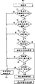
图8表示一份流程图,说明控制信道调度模块的操作;Figure 8 shows a flowchart illustrating the operation of the control channel scheduling module;
图9表示一份流程图,说明控制信道调度模块的间隙装入功能;Figure 9 shows a flow chart illustrating the gap loading function of the control channel scheduling module;
图10a至图10d描述图9的间隙装入功能的一个实例;Figures 10a-10d describe an example of the gap-filling function of Figure 9;
图11表示用以确定一个当前边界的一个状态机;Figure 11 shows a state machine for determining a current boundary;
图12表示一个SPE的调度一览表的链接表结构;Fig. 12 shows the link table structure of the scheduling table of a SPE;
图13表示一个SPE的调度一览表的二叉树结构;Fig. 13 shows the binary tree structure of the scheduling table of a SPE;
图14表示一个SPE的调度一览表的内容可寻址存储器结构。Figure 14 shows the content-addressable memory structure of a schedule table of an SPE.
具体实施方式Detailed ways
参照诸附图的图1-14,将有助于更好地理解本发明,在不同的附图中,相同的数字被用来表示相同的元件。A better understanding of the invention will be aided by reference to Figures 1-14 of the drawings, wherein like numerals are used to designate like elements in the different drawings.
图1a表示一个光学突发交换网络4的总方框图。光学突发交换(OBS)网络4包括多个电子入口边沿路由器6以及多个出口边沿路由器8。各入口边沿路由器6以及各出口边沿路由器8被连接到多个核心光学路由器10。介于各入口边沿路由器6、各出口边沿路由器8以及各核心路由器10之间的连接用光学链路12来实现。每一根光纤都能承载多个光学数据信道。FIG. 1a shows a general block diagram of an optical
在运行中,光学数据的一个数据突发(或者简称为“突发”)是有待于通过网络4进行传送的基本数据块。各入口边沿路由器6以及各出口边沿路由器8负责实施突发的组装和分解功能,并且用作介于光学突发交换网络4以及常规的电子路由器之间的各传承接口。In operation, a data burst (or simply "burst") of optical data is the basic block of data to be transmitted over the
在光学突发交换网络4中,待传送的基本数据块是一个突发,它是具有某些共同属性的分组的一个集合。一个突发由一个突发载荷(称为“数据突发”)和一个突发报头(称为“突发报头分组”或BHP)组成。光学突发交换网络的一项固有的特征就是数据突发以及它的BHP是在不同的信道中发送的,并且分别在每一个网络节点上在光学域和电子域中进行交换。BHP的发送先于它的相关的数据突发的发送一偏移时间toffset(≥0)。其初始值toffset0由(电子)入口边沿路由器6设定。In the optical
在本发明中,一条“信道”被定义为两个相邻的路由器之间的某一单方向的传输能力(以比特/秒为单位来表示)。一条信道可以包括一个波长或一个波长的一部分(例如,在使用时分复用的情况下)。传送数据突发的信道被称为“数据信道”,传送各BHP以及其他控制分组的信道被称为“控制信道”。一个“信道组”是具有共同类型和节点邻接性的一组信道。一条链路被定义为介于两个路由器之间的总的传输能力,其在每一个方向上通常包括一个“数据信道组”(DCG)以及一个“控制信道组”(CCG)。In the present invention, a "channel" is defined as a certain unidirectional transmission capacity (expressed in bit/second) between two adjacent routers. A channel may consist of a wavelength or a fraction of a wavelength (for example, where time division multiplexing is used). The channel carrying the data bursts is called the "data channel" and the channel carrying the BHPs and other control packets is called the "control channel". A "channel group" is a group of channels with a common type and node adjacency. A link is defined as the total transmission capacity between two routers, which generally includes a "data channel group" (DCG) and a "control channel group" (CCG) in each direction.
图1b表示一个核心光学路由器10的方框图。对于每一根光纤12,通过去复用器18,将到达的DCG14从CCG16中分离出来。由光纤延迟线(FDL)19对每一个DCG14进行延时。通过去复用器22将已延时的DCG14分解到各信道20。每一个信道20被输入到位于一个非阻塞的空分交换机(spacial switch)24之中的各自的输入节点。空分交换机24的附加的各输入和输出节点被连接到一个循环缓冲存储器(RB)26。由一个循环交换控制器28对循环缓冲存储器26进行控制。由空分交换机控制器30对空分交换机24进行控制。A block diagram of a core
各CCG14被连接到一个交换机控制单元(SCU)32。SCU包括用于每一个CCG16的一个光学/电子收发信机34。光学/电子收发信机34接收光学的CCG控制信息,并将该光学信息转换为电子信号。电子CCG信息被一个分组处理器36所接收,它将信息送往一个传送器(forwarder)38。用于每一个CCG的传送器被连接到一个交换机40。交换机40的各输出节点被连接到各自的调度器42。各调度器42被连接到一个路径与信道选择器44以及各自的BHP发送模块46。BHP发送模块46被连接到电子/光学收发信机48。电子/光学收发信机48产生输出CCG52,通过多路复用器50,将上述CCG52跟各自的输出DCG54信息组合在一起。路径与信道选择器44还被连接到RB交换机控制器28以及空分交换机控制器30。Each
图1b所示的实施例具有N个输入DCG-CCG对以及N个输出DCG-CCG对52,其中,每一个DCG都有K条信道,并且每一个CCG只有一条信道(k=1)。一个DCG-CCG对52在一根光纤中被传送。一般来说,光学路由器可能是不对称的,一个CCG16的信道数目k可能大于1,并且一个DCG-CCG对52可以在一根以上的光纤12中被传送。在所示的实施例中,有一个具有R条缓冲信道的缓冲信道组(BCG)56。一般来说,可能有一个以上的BCG56。光学交换矩阵(OSM)包括一个(NK+R)×(NK+R)空分交换机以及一个R×R交换机,后者具有波分复用(WDM)光纤延迟线(FDL)缓冲器,用作循环缓冲器(RB)26,用以解决在各出口数据信道中的数据突发竞争问题。空分交换机是一个严格的非阻塞交换机,这意味着在一条入口的数据信道上的一个到达的数据突发可以被切换到任何空闲的出口数据信道。由输入光纤延迟线19引入的延时tfdl必须足够长,使得在相关的数据突发进入空分交换机之前,SCU32有足够的时间去处理一个BHP。The embodiment shown in Fig. 1 b has N input DCG-CCG pairs and N output DCG-CCG pairs 52, where each DCG has K channels and each CCG has only one channel (k=1). One DCG-
R×R RB交换机是一种广播与选择型交换机,在P.Gambini等人于1998年9月发表于IEEE J.Selected Areas inCommunications,第16卷,第7期,第1245-1259页的论文“在KEOPS项中的透明的光学分组交换网络体系结构和示范样机”中,对这种类型的交换机作了描述。假定R×R RB交换机有B根光纤延迟线,其中,第i根光纤延迟线引入了延迟时间Qi,1≤i≤B。在不失一般性的前提下,进一步地假定Q1<Q2<…<QB并且Q0=0,这意味着不使用光纤延迟线缓冲器。要注意的是光纤延迟线缓冲器被所有N个输入DCG所共享,同时每一个光纤延迟线含有R条信道。进入任何入口信道的RB交换机的一个数据突发可能按照所提供的B种延迟时间其中的一种被延时。通过去除RB交换机的功能,就能使图1b中的循环缓冲器退化为无源的光纤延迟线环路,其中,不同的缓冲器信道可以具有不同的延迟。The R×R RB switch is a broadcast and selection switch, published in September 1998 by P.Gambini et al. in the paper " This type of switch is described in the KEOPS item "Transparent Optical Packet-Switched Network Architecture and Demonstration Prototype". It is assumed that the R×R RB switch has B fiber delay lines, wherein the i-th fiber delay line introduces a delay time Q i , 1≤i≤B. Without loss of generality, it is further assumed that Q 1 <Q 2 <...<Q B and Q 0 =0, which means no fiber delay line buffers are used. It should be noted that the fiber delay line buffer is shared by all N input DCGs, and each fiber delay line contains R channels. A data burst entering the RB switch of any ingress channel may be delayed according to one of the B delay times provided. By removing the function of the RB switch, the circular buffer in Fig. 1b can be degenerated into a passive fiber optic delay line loop, where different buffer channels can have different delays.
SCU部分地基于电子路由器。在图1b中,SCU32具有N条输入控制信道和N条输出控制信道。SCU主要地包括分组处理器(PP)36,传送器38,开关结构40,调度器42,BHP传输模块46,路径与信道选择器44,空分交换机控制器30,以及RB交换机控制器28。可以在各电子路由器中找到分组处理器36,传送器38以及开关结构40。其他各部件,特别是调度器,对光学路由器来说是新的。SCU32的设计尽可能多地使用分布式控制,但是对集中化的共享FDL缓冲器的访问控制除外。The SCU is based in part on electronic routers. In FIG. 1b,
分组处理器执行第一层和第二层打开分组(decapsulation)功能,并且为每一个到达的BHP加上时间戳记,用以记录相关的数据突发到达OSM的时间。时间戳记是BHP到达时间、由BHP所传送的突发的偏移时间toffset,以及由输入FDL19引入的延时tfdl的总和。传送器主要地进行传送表的查找,以决定由哪一个出口CCG52来传送BHP。相关的数据突发将被切换到相应的DCG54。可以在一种无连接或面向连接的方式中来完成传送。The Packet Handler performs
每一个DCG-CCG对52都有一个调度器。调度器42根据BHP所携带的信息对出口DCG54的一条数据信道上的数据突发的交换进行调度。若找到一条自由的数据信道,则调度器42将对出口控制信道上的BHP的传输进行调度,通过令偏移时间toffset尽可能地接近toffset0,尝试使BHP及其相关的数据突发实现“再同步”。在数据突发和BHP二者被成功地调度之后,若不需要通过循环缓冲器26来提供延迟,则调度器42将向空分交换机控制器30发送配置信息,否则,它也将向RB交换机控制器28发送配置信息。Each DCG-
调度判断过程的数据流示于图2。在判断框60,调度器42确定是否有足够的时间对到来的数据突发进行调度。若有,则调度器确定是否可以对该数据突发进行调度,即,在用于数据突发的指定的DCG54中,是否还有未被占用的空间。为了对该数据突发进行调度,在指定的输出DCG中,必须有一个可用的空间供数据突发使用。这个空间可以在一个时间窗口内开始,该时间窗口开始于数据突发到达空分交换机24的时间点上,一直延伸到循环缓冲器26所能提供的最大延时为止。若该数据突发可以被调度,则在判断框64中,调度器42必须确定在输出CCG52中,是否有可用于BHP的空间。The data flow of the scheduling judgment process is shown in Figure 2. At
若在各判断框60,62或64中,任何一次判断的结果为否,则在方框65中,数据突发和BHP都被丢弃。若在各判断框60,62或64中,所有的判断的结果均为是,则调度器向路径与信道选择器44发送调度信息。从调度器送往路径与信道选择器的配置信息包括到来的DCG标识符,到来的数据信道标识符,外送的DCG标识符,外送的数据信道标识符,数据突发到达空分交换机的时间,数据突发持续时间,FDL标识符i(所要求的延迟时间为Qi,0≤i≤B)。If the result of any one of the decisions in each
若FDL标识符为0,则意味着不需要FDL缓冲器,路径与信道选择器44将仅向空分交换机控制器30传送配置信息。否则,在判断框68中,路径与信道选择器44将搜索一条通往RB交换机26的空闲的入口缓冲器信道。若找到的话,在判断框70,路径与信道选择器44将从RB交换机26中寻找一条空闲的出口缓冲器信道,以便在RB交换机26里面经过特定的延时之后,令数据突发重新进入空分交换机。假定一旦数据突发进入RB交换机,它将按照来自集合{Q1,Q2,…,QB}的任何一个离散的时间来产生延迟。若不是这样的情况,则路径与信道选择器44将必须考虑RB交换机的体系结构。若进出RB交换机26的两条空闲信道都被找到,则路径与信道选择器44将向空分交换机控制器30以及RB交换机控制器28发送配置信息,并将一个确认(ACK)信号送回调度器42。否则,它将一个不确认(NACK)信号送回调度器42,同时在框65中,BHP以及数据突发将被丢弃。If the FDL identifier is 0, it means that no FDL buffer is needed, and the route and
从路径与信道选择器44送往空分交换机控制器30的配置信息包括到来的DCG标识符,到来的数据信道标识符,外送的DCG标识符,外送的数据信道标识符,数据突发到达空分交换机的时间,数据突发持续时间,FDL标识符i(所要求的延迟时间为Qi,0≤i≤B)。若i>0,则该信息还包括到来的BCG标识符(送往RB交换机),到来的缓冲信道标识符(送往RB交换机),外送的BCG标识符(来自RB交换机),以及外送的缓冲信道标识符(来自RB交换机)。The configuration information sent from path and
从路径与信道选择器送往RB交换机控制器的配置信息包括到来的BCG标识符(送往RB交换机),到来的缓冲信道标识符(送往RB交换机),外送的BCG标识符(来自RB交换机),外送的缓冲信道标识符(来自RB交换机),数据突发到达RB交换机的时间,数据突发持续时间,FDL标识符i(所要求的延迟时间为Qi,0≤i≤B)。The configuration information sent from the path and channel selector to the RB switch controller includes the incoming BCG identifier (sent to the RB switch), the incoming buffer channel identifier (sent to the RB switch), and the outgoing BCG identifier (from the RB switch), the outgoing buffer channel identifier (from the RB switch), the time when the data burst arrives at the RB switch, the duration of the data burst, the FDL identifier i (the required delay time is Q i , 0≤i≤B ).
空分交换机控制器30以及RB交换机控制器28将进行从已接收的配置信息到在设定内部路径的过程中所涉及的各物理部件的映射,并且及时地配置各交换机,以便让数据突发迅速地通过光学路由器10。当FDL标识符大于0时,空分交换机控制器30将在空分交换机中设置两条内部路经,当数据突发到达空分交换机时,一条路径从到来的数据信道通往到来的循环缓冲器信道,当数据突发重新进入空分交换机时,另一条路径则从外送的缓冲器信道通往外送的数据信道。在接收到来自路径与信道选择器44的ACK之后,调度器42将更新已选定的数据和控制信道的状态信息,同时作好准备以便处理一个新的BHP。The space
最后,BHP传输模块按照调度器所指定的时间来安排各BHP的传输。Finally, the BHP transmission module arranges the transmission of each BHP according to the time specified by the scheduler.
以上是在光学路由器中,关于如何去调度数据突发的一般描述。若希望这样做的话,可以容易地根据下述的各项设计原理,通过R×R循环缓冲器交换机将各数据突发循环一次以上。The above is a general description of how to schedule data bursts in an optical router. If this is desired, each data burst can be easily cycled through the RxR circular buffer switch more than once according to the design principles described below.
图3表示一个调度器42的方框图。调度器42包括一个调度队列80,一个BHP处理器82,一个数据信道调度(DCS)模块84,以及一个控制信道调度(CCS)模块86。每一个调度器只需要跟踪其相关的外送DCG54以及外送CCG52的忙/闲周期。FIG. 3 shows a block diagram of a
从电子交换机到达的各BHP首先被存储在调度队列80之中。对基本操作来说,所需的一切就是一个调度队列80,然而,可以为不同的业务等级保留虚拟的各调度队列80。根据各BHP的到达顺序或者根据它们的相关的各数据突发的实际到达顺序,来为每一个队列80提供服务。BHP处理器82对数据和控制信道的调度过程进行协调,并向路径与信道选择器44发送配置信息。Each BHP arriving from an electronic exchange is first stored in dispatch queue 80 . For basic operation, all that is required is one dispatch queue 80, however, virtual dispatch queues 80 may be reserved for different traffic classes. Each queue 80 is serviced according to the order of arrival of the BHPs or according to the actual order of arrival of their associated data bursts. The BHP processor 82 coordinates the scheduling of the data and control channels and sends configuration information to the path and
BHP处理器82首先触发DCS模块84,以便在所希望的输出DCS54的一条数据信道上对数据突发(DB)进行调度。在确定该数据突发何时将被送出之后,BHP处理器就触发CCS模块86,以便在一条相关的控制信道上对BHP进行调度。The BHP processor 82 first triggers the DCS module 84 to schedule a data burst (DB) on a data channel of the desired
图4说明一个用以在一条控制信道上传送BHP信息的同步载荷包封(SPE)100的表示。SPE100可能类似于在SONET中使用的STS-1帧结构。SPE100被描述为一个数组(data array),该数组的每一行都有一个传输开销字段102以及一个数据字段104。在一个STS-1SPE中,9行中的每一行都有一个3字节的传输开销字段102以及一个87字节的数据字段104。在本发明中,可以适当地使用不同于STS-1SPE的数据结构。FIG. 4 illustrates a representation of a Synchronous Payload Envelope (SPE) 100 for conveying BHP information on a control channel.
图5表示集群为一个“边界(frontier)”110的一组邻接的各SPE100集合。边界表示在BHP的到达及其可能的离开之间,可能发送的一组最大数目的SPE。介于BHP的到达及其可能的离开之间的时间被表示为tfrontier,并且它等于tioffset max+tfdl+tbuffer max+tpadding-tminproc之和,式中,toffset max为介于BHP及其相关的DB之间的最大允许偏移时间,tfdl为在输入FDL19中,DB被延迟的时间,tbuffer max为在循环缓冲器26中,一个数据突发可能被延迟的最大时间,tpadding为到达最后一个完整的SPE(每一个边界都有整数个SPE100)所需的被添加的时间,并且tmin proc为用于BHP的最短处理时间。为了便于说明,在计算中tmin proc被忽略不计。FIG. 5 shows a contiguous set of
图6表示在调度器42中,用以对各BHP的传输进行调度的控制信道调度模块86的方框图。控制信道调度模块86包括一个调度处理器114以及一个调度一览表(calendar)存储器116。调度一览表存储器116存储SPE信息。调度处理器114确定一个当前BHP在SPE100中的最佳位置。FIG. 6 shows a block diagram of the control
要注意的是,可以在CCG上传送各BHP以外的控制信息。各BHP以及其他控制信息在这里可以被称为各控制分组。It is to be noted that control information other than each BHP can be transmitted on the CCG. BHPs and other control information may be referred to herein as control packets.
在各SPE100中,在CCG16之上发送控制信息。各SPE在逻辑上被划分为各边界,如图7所示。由于一个BHP的离开时间只可能出现在当前边界110或者下一个边界110之中,所以在任何给定时间内,在控制信道调度一览表存储器116中,需要只有两个边界110,即边界(n)和边界(n+1)的一个调度窗口。随着时间的推移,当前的和随后的边界都被加1,并且所有已使用过的边界以及在它们的内容中的各数据项都被送回到垃圾箱里面。在初始化时,向当前边界赋予索引(index)“0”,向下一个边界赋予索引“1”,依此类推。In each
图8表示用于调度一个BHP的流程图。在方框120,从队列80中取出一个BHP。然后,在方框122,控制信道调度模块86取出一个当前时间并确定一个当前边界。下面将结合图11,更详细地讨论当前边界的确定方法。在这里,当前边界被表示为边界“F”。Figure 8 shows a flowchart for scheduling a BHP. At block 120, a BHP is taken from the queue 80. Then, at block 122, the control
在方框124中,确定BHP的离开时间。BHP的离开时间先于相关的数据突发的离开时间一段预定的最小偏移时间。一旦离开时间被确定,就能确定离开边界D。离开边界D可以跟当前边界C相同,或者它可能就是下一个后继的边界。In block 124, the departure time of the BHP is determined. The departure time of the BHP precedes the departure time of the associated data burst by a predetermined minimum offset time. Once the departure time is determined, the departure boundary D can be determined. The leaving boundary D may be the same as the current boundary C, or it may be the next successive boundary.
在方框128,对处于与BHP离开时间相对应的离开边界之中的SPE进行标识。在方框130,在这个SPE之中的一个间隙被定位。下面将结合图12-14来说明用以对间隙进行定位的3种方法。At block 128, the SPEs within the departure boundary corresponding to the BHP departure time are identified. At block 130, a gap within the SPE is located. Three methods for positioning the gap will be described below with reference to FIGS. 12-14 .
判断框132确定当前的BHP能否装入在方框130中所标识的间隙。若能,则在方框134中,在该间隙中对BHP进行调度以离开。然而,在某些情况下,BHP可能装不进该间隙。在这些情况下,只要该间隙位于偏移时间窗口之中(即,BHP的离开先于相关的数据突发的离开的时间不大于toffset max),则在方框136和138,控制信道调度模块将尝试把BHP装进一个更早的间隙之中(由此增加了介于BHP及其相关的突发之间的时间差)。对每一个间隙,重复进行判断框132的测试,以保证BHP能装进该间隙之中。若该BHP不能装进在偏移时间窗口以内的任何一个间隙,则BHP的调度宣告失败。Decision block 132 determines whether the current BHP can fit into the gap identified in block 130 . If so, then in block 134 the BHP is scheduled to leave during the gap. However, in some cases the BHP may not fit into this gap. In these cases, as long as the gap is within the offset time window (i.e., the departure of the BHP does not precede the departure of the associated data burst by more than t offset max ), then at blocks 136 and 138, the control channel schedules The module will try to fit the BHP into an earlier gap (thereby increasing the time difference between the BHP and its associated burst). For each gap, the test of decision block 132 is repeated to ensure that the BHP fits into the gap. If the BHP cannot fit into any gap within the offset time window, the scheduling of the BHP fails.
图9结合图10a-d,更详细地说明方框132。判断框142确定有待于接受调度的BHP是否开始于在相关的SPE中的一个开销字节。在图10a中,以图形方式来表示这种情形。在该图中,BHP144是有待于接受调度的BHP。BHP144的起始点被表示为“S”。这个点位于一个先前调度的控制分组146之后,以及位于另一个先前调度的控制分组148之前。然而,在图10a中,S处于一个传输开销区102之中(见图4)。相应地,BHP144的起始点被移动到一个先前的点S’处,以避开该SPE的传输开销区(方框150),如图10b所示。在判断框152,若在移动到S’之后,现在BHP位于偏移时间窗口以外,或者跟先前的分组146重叠,则在方框154,返回一个“假”。另一方面,若S’不在偏移时间窗口以外,并且不跟先前的分组146重叠,则在方框156,计算一种扩增的情况,以产生BHP’158,如图10c所示。Figure 9 illustrates block 132 in more detail in conjunction with Figures 10a-d. Decision block 142 determines whether the BHP to be scheduled begins with an overhead byte in the associated SPE. In Fig. 10a, this situation is represented graphically. In this figure,
BHP144扩大到BHP’158需要考虑各SPE中用于传输开销(字段)102的部分。如图10c所示,BHP’可以跟后继的分组148再次发生重叠。在判断框160,若BHP’跟后继的控制分组158发生重叠,则起始点被移动到一个更早的时间S”,以便避开后继的分组(方框162)。在判断框164,若在延迟到S”之后,BHP”158现在处于偏移时间窗口以外,或者跟先前的分组146重叠,则在方框166,返回一个“假”。另一方面,若S”不在偏移时间窗口以外,并且不跟先前的分组146重叠,则流程控制返回到判断框142,以确定新的起始点位置是否处于一个开销区之中。该循环将继续进行,直到在方框160中,BHP不跟后继的控制分组148发生重叠为止(见图10d),这时,在方框168将返回一个“真”。The extension of
可能有若干寂静期,这将导致控制信道调度模块失去对在调度一览表中的当前位置的跟踪。在优选的实施例中,在核心路由器的接收端,有一个定时器可用于运行一个状态机。描述运行/空闲状态机170的运作的状态图示于图11。There may be periods of silence which will cause the control channel scheduling module to lose track of its current position in the scheduling table. In the preferred embodiment, at the receiving end of the core router, a timer is available to run a state machine. A state diagram describing the operation of the run/idle state machine 170 is shown in FIG. 11 .
运行/空闲状态机170有两种状态:运行状态172和空闲状态174。一开始,一个时钟被设置为两倍边界持续时间的数值。在运行状态中,时钟一直进行计数,直到出现下列两种情况其中之一为止:(1)一个控制分组从到来的控制信道组中的任何控制信道到达,或(2)时钟停止(run out)。表示两个边界已经通过,没有出现一个控制分组。当状态机170处于运行状态172时,若有一个控制分组到达,则时钟被复位,同时一个“R”代码连同该分组一起被送往正在进行处理的队列。若时钟停止,则状态机170进入空闲状态174。在空闲状态174,只能出现该分组的到达。一旦有一个分组到达,时钟将被复位,一个“I”代码连同BHP一起被发送,并且状态机返回到运行状态172。Run/idle state machine 170 has two states: run state 172 and idle state 174 . Initially, a clock is set to twice the value of the boundary duration. In the running state, the clock keeps counting until one of the following two conditions occurs: (1) a control packet arrives from any control channel in the incoming control channel group, or (2) the clock stops (run out) . Indicates that both boundaries have been passed without a control packet. When the state machine 170 is in the run state 172, if a control packet arrives, the clock is reset and an "R" code is sent to the processing queue along with the packet. If the clock is stopped, state machine 170 enters idle state 174 . In the idle state 174, only the arrival of the packet can occur. Once a packet arrives, the clock is reset, an "I" code is sent along with the BHP, and the state machine returns to run state 172.
在控制信道调度模块86,按照一个系统时钟来进行调度。若跟一个BHP相关的代码为“R”,则系统时钟被读出作为当前时间。通过将当前时间除以边界数值,所得商的最低位将表示在两个边界中,哪一个是当前的边界。若最低位跟先前所计算的数值的最低位相同,则当前的边界没有发生改变。若最低位已经从它的前一个当前数值发生改变,则当前的边界被更新,指向下一个边界,同时前一个边界被送回到垃圾箱。一个新的边界被添加,作为第二边界。In the control
若该分组具有一个I代码,则系统时钟、当前和下一个边界都被复位,同时开始进行调度。使用这个方法,系统将永远不会出现时钟溢出的情况。If the packet has an I code, the system clock, current and next boundaries are all reset, and scheduling begins. Using this method, the system will never experience clock overflow.
回到控制信道调度,将外送时间除以边界数值,并且所得商的二进制等价物的最低位定义了需要在其中对控制分组进行调度的边界的数目。除法运算的余数定义了在边界之中的参考时间,据此可以对SPE进行定位,以便对控制分组进行调度。Returning to control channel scheduling, the outgoing time is divided by the boundary value, and the lowest bit of the binary equivalent of the resulting quotient defines the number of boundaries within which control packets need to be scheduled. The remainder of the division operation defines the reference time within the boundary from which the SPE can be located for scheduling control packets.
为了进行调度,每一个SPE都有一个预约一览表,通过记忆以字节数目表示的每一个它们的起始字节和长度,以记录先前已进行调度的各控制分组。在这里,叙述了用于在SPE层次上安排数据结构的3种不同的方法:(1)线性链接表,(2)二叉树,(3)并行内容寻址。还可以使用其他方法。For scheduling, each SPE has a reservation list, by memorizing the start byte and length of each of them represented by the number of bytes, to record the control packets that have been previously scheduled. Here, 3 different methods for arranging data structures at the SPE level are described: (1) linear linked list, (2) binary tree, (3) parallel content addressing. Other methods can also be used.
图12表示用于一个SPE的调度一览表的链接表结构。在这个方法中,涉及已经调度的各控制分组的数据被排列在线性链接表之中。在这个方法中,当对一个新的分组进行调度时,就在该表上进行一次线性检索。线性检索的时间复杂性为O(n),式中n为链接表中各项的数目。Fig. 12 shows the link list structure of the schedule table for one SPE. In this method, data related to the control packets that have been scheduled are arranged in a linearly linked list. In this approach, a linear search is performed on the table when a new packet is scheduled. The time complexity of linear retrieval is O(n), where n is the number of items in the linked list.
图13表示一种二叉树方法的方框图。随着对各控制分组进行调度,根据起始位置,它们被定位在二叉树之中(通过SPE中的字节位置)。在图13所示的二叉树中,对位于起始位置13,7,11,2,20,8,12和9的各控制分组(按照顺序)进行调度。在二叉树中的每一个节点都包括相关控制分组的起始位置和长度。每一个节点可能有,最多,一个父节点和两个子节点。若有两个子入口,则其中一个必须具有较小的起始位置,而另一个必须具有较大的起始位置。根据该起始位置大于或小于在每一个节点上的起始位置,跟随一条通过该树的路径,将新的入口添加到该树之中。新的入口被添加到第一个可用的节点上。Fig. 13 shows a block diagram of a binary tree method. As the control packets are scheduled, they are positioned in the binary tree (by byte position in the SPE) according to their starting position. In the binary tree shown in FIG. 13, the respective control packets located at the starting positions 13, 7, 11, 2, 20, 8, 12 and 9 are scheduled (in order). Each node in the binary tree contains the start position and length of the associated control packet. Each node may have, at most, one parent node and two child nodes. If there are two sub-entries, one must have a smaller starting position and the other must have a larger starting position. A new entry is added to the tree by following a path through the tree based on whether the starting position is greater or less than the starting position at each node. New entries are added on the first available node.
为了对处于一个给定的起始位置的BHP进行调度,进行针对先前的和后继的各分组的检索。因此,对一个开始于字节“10”的BHP来说,要对位于字节“9”和“11”的分组进行检索。这种检索的时间复杂性为O(logn),式中,n为在该树中的数据项的数目。In order to schedule a BHP at a given starting position, a search is made for previous and subsequent packets. Thus, for a BHP starting at byte "10", packets at bytes "9" and "11" are retrieved. The time complexity of this retrieval is O(logn), where n is the number of data items in the tree.
图14表示使用一个内容可寻址的存储器单元180的一种检索方法。可以以并行方式对每一个存储器单元180进行访问。每一个存储器单元都存储着在针对一个SPE的调度图中的每一个间隙的起始字节和末尾字节。进行一次并行比较(用多个圆182来描绘),以定位一个间隙,该间隙能根据偏移数值来定位该控制分组。只有一次成功的比较才能导致(将比较结果)写入到结果寄存器184中去。这种结构的时间复杂性为O(1)。Figure 14 shows a retrieval method using a content
本发明相对于现有技术来说提供了显著的优点。首先,它允许对各BHP以及其他各控制分组进行有效的和快速的调度。其次,使用各边界使得需要被存储到控制信道调度模块之中的调度信息的数量最小化。第三,可以使用同步载荷包封来传送信息。The present invention provides significant advantages over the prior art. First, it allows efficient and fast scheduling of BHPs as well as other control packets. Second, the use of boundaries minimizes the amount of scheduling information that needs to be stored into the control channel scheduling module. Third, information can be transferred using isochronous payload packets.
虽然本发明的详细说明是针对一些示范性的实施例来进行叙述的,但是,本领域技术人员可提出这些实施例的各种修改方法以及各种可供替代的实施例。凡是处于权利要求书的范围以内的任何修改或者可供替代的实施例都被纳入本发明之中。Although the detailed description of the present invention has been described with respect to some exemplary embodiments, various modifications of these embodiments and various alternative embodiments can be suggested by those skilled in the art. Any modifications or alternative embodiments within the scope of the claims are included in the present invention.
Claims (5)
Applications Claiming Priority (2)
| Application Number | Priority Date | Filing Date | Title |
|---|---|---|---|
| US10/177,201 US7257127B1 (en) | 2002-06-21 | 2002-06-21 | Method and apparatus for burst scheduling |
| US10/177,201 | 2002-06-21 |
Publications (2)
| Publication Number | Publication Date |
|---|---|
| CN1469586A true CN1469586A (en) | 2004-01-21 |
| CN100568810C CN100568810C (en) | 2009-12-09 |
Family
ID=29717858
Family Applications (1)
| Application Number | Title | Priority Date | Filing Date |
|---|---|---|---|
| CNB031494013A Expired - Fee Related CN100568810C (en) | 2002-06-21 | 2003-06-20 | Apparatus for burst scheduling |
Country Status (4)
| Country | Link |
|---|---|
| US (1) | US7257127B1 (en) |
| EP (1) | EP1377106B1 (en) |
| CN (1) | CN100568810C (en) |
| AT (1) | ATE550883T1 (en) |
Cited By (1)
| Publication number | Priority date | Publication date | Assignee | Title |
|---|---|---|---|---|
| CN101447914B (en) * | 2007-11-27 | 2012-08-08 | 华为技术有限公司 | Multichannel scheduling method, and system and device thereof |
Families Citing this family (7)
| Publication number | Priority date | Publication date | Assignee | Title |
|---|---|---|---|---|
| EP2302961B1 (en) * | 2002-09-20 | 2013-11-06 | Fujitsu Limited | Resource information transmission for multicasting in a wireless network |
| US7528614B2 (en) | 2004-12-22 | 2009-05-05 | Applied Materials, Inc. | Apparatus and method for voltage contrast analysis of a wafer using a tilted pre-charging beam |
| US7468974B1 (en) * | 2003-09-22 | 2008-12-23 | Pmc-Sierra, Inc. | Efficient strictly non-blocking multicast switch architecture for time division multiplexed traffic |
| US7567572B1 (en) * | 2004-01-09 | 2009-07-28 | Cisco Technology, Inc. | 2-rate scheduling based on search trees with configurable excess bandwidth sharing |
| KR100603254B1 (en) * | 2004-12-27 | 2006-07-24 | 삼성전자주식회사 | Filling of empty transmission section and transmitting burst data in optical burst switching network |
| CN101232438B (en) * | 2007-01-26 | 2012-10-03 | 华为技术有限公司 | Method for implementing outburst packet delay and core node |
| CN107172026A (en) * | 2017-05-05 | 2017-09-15 | 广西师范大学 | A kind of burst transfer dispatching method of mobile media broadcasting network |
Family Cites Families (5)
| Publication number | Priority date | Publication date | Assignee | Title |
|---|---|---|---|---|
| US6470347B1 (en) * | 1999-09-01 | 2002-10-22 | International Business Machines Corporation | Method, system, program, and data structure for a dense array storing character strings |
| US6661789B1 (en) * | 1999-09-10 | 2003-12-09 | Alcatel | Dynamic burstification based on fully/partially shared multicast entities |
| US6721315B1 (en) * | 1999-09-30 | 2004-04-13 | Alcatel | Control architecture in optical burst-switched networks |
| US6671256B1 (en) * | 2000-02-03 | 2003-12-30 | Alcatel | Data channel reservation in optical burst-switched networks |
| US6577635B2 (en) * | 2001-02-26 | 2003-06-10 | Maple Optical Systems, Inc. | Data packet transmission scheduling |
-
2002
- 2002-06-21 US US10/177,201 patent/US7257127B1/en not_active Expired - Fee Related
-
2003
- 2003-06-06 AT AT03012861T patent/ATE550883T1/en active
- 2003-06-06 EP EP03012861A patent/EP1377106B1/en not_active Expired - Lifetime
- 2003-06-20 CN CNB031494013A patent/CN100568810C/en not_active Expired - Fee Related
Cited By (1)
| Publication number | Priority date | Publication date | Assignee | Title |
|---|---|---|---|---|
| CN101447914B (en) * | 2007-11-27 | 2012-08-08 | 华为技术有限公司 | Multichannel scheduling method, and system and device thereof |
Also Published As
| Publication number | Publication date |
|---|---|
| EP1377106B1 (en) | 2012-03-21 |
| US7257127B1 (en) | 2007-08-14 |
| ATE550883T1 (en) | 2012-04-15 |
| CN100568810C (en) | 2009-12-09 |
| EP1377106A3 (en) | 2009-01-14 |
| EP1377106A2 (en) | 2004-01-02 |
Similar Documents
| Publication | Publication Date | Title |
|---|---|---|
| US10182021B2 (en) | Crossbar switch and recursive scheduling | |
| JP2923693B2 (en) | Large capacity ATM switch | |
| US7023841B2 (en) | Three-stage switch fabric with buffered crossbar devices | |
| US7161906B2 (en) | Three-stage switch fabric with input device features | |
| US7693142B2 (en) | Scalable router-switch | |
| US7079485B1 (en) | Multiservice switching system with distributed switch fabric | |
| US6542511B1 (en) | Programmable transport and network architecture | |
| US7742489B2 (en) | Multi-protocol network interface card | |
| US7940786B2 (en) | System and method for communicating data using a common switch fabric | |
| US7324537B2 (en) | Switching device with asymmetric port speeds | |
| CN1035927A (en) | The method and apparatus of hybrid packet switching | |
| US6819870B1 (en) | All-optical networking optical fiber line delay buffering apparatus and method | |
| JPH08298522A (en) | Selective ejection system and method to maintain space priority order to be used in common memory asynchronous transfer mode switch | |
| KR20040032880A (en) | Scalable switching system with intelligent control | |
| US20020118419A1 (en) | Unified associative memory of data channel schedulers in an optical router | |
| EP1220563A2 (en) | Channel scheduling in optical routers | |
| JPH10285185A (en) | Method for scheduling data cell transmission in atm network | |
| US20080273546A1 (en) | Data switch and a method of switching | |
| CN1359241A (en) | Distribution type dispatcher for group exchanger and passive optical network | |
| US20020054732A1 (en) | Optical burst scheduling using partitioned channel groups | |
| CN100568810C (en) | Apparatus for burst scheduling | |
| US5757799A (en) | High speed packet switch | |
| Rahnema | The fast packet ring switch: A high-performance efficient architecture with multicast capability | |
| EP1217863A2 (en) | Unified associative memory of data channel schedulers in an optical router | |
| Ren | Bandwidth allocation and congestion control for broadband ISDN |
Legal Events
| Date | Code | Title | Description |
|---|---|---|---|
| C06 | Publication | ||
| PB01 | Publication | ||
| C10 | Entry into substantive examination | ||
| SE01 | Entry into force of request for substantive examination | ||
| C14 | Grant of patent or utility model | ||
| GR01 | Patent grant | ||
| CF01 | Termination of patent right due to non-payment of annual fee |
Granted publication date: 20091209 Termination date: 20150620 |
|
| EXPY | Termination of patent right or utility model |