CN1423150A - Observation device - Google Patents
Observation device Download PDFInfo
- Publication number
- CN1423150A CN1423150A CN02153885A CN02153885A CN1423150A CN 1423150 A CN1423150 A CN 1423150A CN 02153885 A CN02153885 A CN 02153885A CN 02153885 A CN02153885 A CN 02153885A CN 1423150 A CN1423150 A CN 1423150A
- Authority
- CN
- China
- Prior art keywords
- lens
- astigmatism
- optical
- observation
- variable
- Prior art date
- Legal status (The legal status is an assumption and is not a legal conclusion. Google has not performed a legal analysis and makes no representation as to the accuracy of the status listed.)
- Granted
Links
- 230000003287 optical effect Effects 0.000 claims abstract description 252
- 201000009310 astigmatism Diseases 0.000 claims abstract description 152
- 210000005252 bulbus oculi Anatomy 0.000 claims abstract description 44
- 238000003384 imaging method Methods 0.000 claims abstract description 42
- 230000004075 alteration Effects 0.000 claims description 52
- 210000001508 eye Anatomy 0.000 claims description 12
- 238000011282 treatment Methods 0.000 claims description 7
- 230000001225 therapeutic effect Effects 0.000 claims description 6
- 230000008859 change Effects 0.000 claims description 5
- 238000004458 analytical method Methods 0.000 claims description 4
- 238000010191 image analysis Methods 0.000 claims description 2
- 230000008030 elimination Effects 0.000 claims 2
- 238000003379 elimination reaction Methods 0.000 claims 2
- 230000001915 proofreading effect Effects 0.000 claims 2
- 238000006243 chemical reaction Methods 0.000 abstract 1
- 238000010586 diagram Methods 0.000 description 21
- 210000001747 pupil Anatomy 0.000 description 15
- 238000005286 illumination Methods 0.000 description 10
- 230000002093 peripheral effect Effects 0.000 description 6
- 210000004087 cornea Anatomy 0.000 description 5
- 239000003086 colorant Substances 0.000 description 4
- 239000006185 dispersion Substances 0.000 description 4
- 210000004204 blood vessel Anatomy 0.000 description 3
- 230000000694 effects Effects 0.000 description 3
- 238000000926 separation method Methods 0.000 description 3
- 239000000284 extract Substances 0.000 description 2
- 230000004907 flux Effects 0.000 description 2
- 238000001356 surgical procedure Methods 0.000 description 2
- 238000005345 coagulation Methods 0.000 description 1
- 230000015271 coagulation Effects 0.000 description 1
- 239000007943 implant Substances 0.000 description 1
- 230000006872 improvement Effects 0.000 description 1
- 230000001678 irradiating effect Effects 0.000 description 1
- 238000013532 laser treatment Methods 0.000 description 1
- 239000003550 marker Substances 0.000 description 1
- 238000000034 method Methods 0.000 description 1
- 230000004044 response Effects 0.000 description 1
Images


Classifications
-
- A—HUMAN NECESSITIES
- A61—MEDICAL OR VETERINARY SCIENCE; HYGIENE
- A61B—DIAGNOSIS; SURGERY; IDENTIFICATION
- A61B3/00—Apparatus for testing the eyes; Instruments for examining the eyes
- A61B3/10—Objective types, i.e. instruments for examining the eyes independent of the patients' perceptions or reactions
- A61B3/13—Ophthalmic microscopes
Landscapes
- Life Sciences & Earth Sciences (AREA)
- Health & Medical Sciences (AREA)
- Medical Informatics (AREA)
- Molecular Biology (AREA)
- Ophthalmology & Optometry (AREA)
- Engineering & Computer Science (AREA)
- Biomedical Technology (AREA)
- Heart & Thoracic Surgery (AREA)
- Physics & Mathematics (AREA)
- Biophysics (AREA)
- Surgery (AREA)
- Animal Behavior & Ethology (AREA)
- General Health & Medical Sciences (AREA)
- Public Health (AREA)
- Veterinary Medicine (AREA)
- Eye Examination Apparatus (AREA)
- Lenses (AREA)
- Microscoopes, Condenser (AREA)
Abstract
一种能消除散光的观察装置。在光学观察系统(13a)从物镜(19)到目镜(22)的观察路径设有可变焦度透镜系统(20)。光学观察系统中从物镜(19)到可变焦度透镜系统(20)的一部分光学观察系统形成观察路径,通过该路径从手术眼球(E)眼底(Er)的反射光束平行到达可变焦度透镜系统(20)。从可变焦度透镜系统(20)到成像透镜(22)一部分光学观察系统形成观察路径,通过该路径从可变焦度透镜系统(20)获得的反射光束平行到达转换目镜(26)。在光学观察系统(13a)从物镜(19)到目镜(26)的观察路径有消除散光的光学元件(61),以消除在(棱镜)光学元件(60)压在手术眼球(E)上产生的散光。

A viewing device that eliminates astigmatism. A variable focus lens system (20) is provided on the observation path of the optical observation system (13a) from the objective lens (19) to the eyepiece (22). A part of the optical observation system from the objective lens (19) to the variable focus lens system (20) in the optical observation system forms an observation path, through which the reflected beam from the surgical eyeball (E) fundus (Er) reaches the variable focus lens system in parallel (20). A part of the optical observation system from the zoom lens system (20) to the imaging lens (22) forms an observation path, through which the reflected light beam obtained from the zoom lens system (20) reaches the conversion eyepiece (26) in parallel. In the observation path of the optical observation system (13a) from the objective lens (19) to the eyepiece (26), there is an optical element (61) to eliminate astigmatism, so as to eliminate the pressure generated by the (prism) optical element (60) on the surgical eyeball (E). of astigmatism.
Description
技术领域technical field
本发明涉及一种观察装置如手术显微镜或裂隙灯的改进。The present invention relates to an improvement of an observation device such as an operating microscope or a slit lamp.
背景技术Background technique
图1所示为现有技术中用作观察装置的手术显微镜。图1中有支撑柱1、支撑臂2、托架3,其中的托架3用来将手术显微镜连接到支撑臂的端部。Fig. 1 shows a surgical microscope used as an observation device in the prior art. In Fig. 1 there are a
支撑臂2由L形臂4和摇臂5构成。L形臂4与支撑臂2的顶端相连从而能水平旋转。摇臂5通过其内的一个弹簧向上偏移。The support arm 2 is composed of an L-shaped arm 4 and a rocker arm 5 . The L-shaped arm 4 is connected to the top end of the support arm 2 so as to be able to rotate horizontally. The rocker arm 5 is biased upwards by a spring inside it.
臂6在支撑上可水平旋转,其布置在摇臂5的端部并向下。同时托架3与臂6相连。The arm 6 is horizontally rotatable on a support which is arranged at the end of the rocker arm 5 and downwards. At the same time the
手术显微镜10连接在托架3上。手术显微镜10有一个镜筒11。镜筒11中有一个光学观察系统。镜筒11带有一个目镜镜筒11’。The surgical microscope 10 is attached to the
如图2所示,手术显微镜10具有例如一个光学照明系统12和一个光学观察系统13。其中光学照明系统12由照明光源14、一个聚光透镜15、一个照明场阑16、一个准直管透镜17以及一个棱镜18构成。附图标记18b表示棱镜18的反射面。来自照明光源14的照明光通过聚光透镜15、照明场阑16、准直管透镜17和棱镜18导引到光学观察系统13的物镜19上。然后再导引到例如手术眼球E的眼底Er,以便照亮眼底Er。注意,标记Ea表示手术眼球的瞳孔,Eb为虹膜,Ec为角膜。As shown in FIG. 2 , the surgical microscope 10 has, for example, an
如图3所示,光学观察系统13由右眼光学观察系统13a和左眼光学观察系统13b构成。右眼光学观察系统13a包括一个由镜头20a、20b、20c构成的(可变焦距透镜系统)可变焦度透镜系统20、一个分束器21、一个成像透镜22、一个像转正棱镜23、一个光瞳调节棱镜24、一个场阑25以及一个目镜26。注意标记2a1表示入射光瞳,26a表示出射点。As shown in FIG. 3 , the
同样,左眼光学观察系统13b包括一个由透镜30a、30b、30c构成的(可变焦距透镜系统)可变焦度透镜系统30、一个分束器31、一个成像透镜32、一个像转正棱镜33、一个眼距调节棱镜34、一个场阑35以及一个目镜36。注意标记2b1表示入射光瞳,36a表示出射点。Equally, the left-eye
从被测眼球E的眼底Er反射回来的光束从光学观察系统13a和13b的物镜19到目镜26和36一直导向操作者的眼睛,从而使操作者能观察到眼底Er。从眼底Er反射回来的一部分光束通过分束器21和31分离并导向辅助光学观察系统40供助手和TV摄像系统50使用。The light beams reflected from the fundus Er of the eyeball E to be measured are directed from the
图3中,41和51表示成像透镜,42和52表示反射镜,43表示目镜,TV摄像机53表示TV摄像机。TV摄像机53具有一个CCD成像元件,其用作图像接收装置53a。In FIG. 3 , 41 and 51 represent imaging lenses, 42 and 52 represent mirrors, 43 represents an eyepiece, and a
如图4所示,照明光学系统12的出射光瞳18a紧靠着光学观察系统13a和13b的观察路径2a2和2b2布置。图4中的标记O表示物镜19的光轴,O1表示左眼光学观察系统13a的观察光轴,O2表示右眼光学观察系统13b的观察光轴。As shown in FIG. 4, the
顺便说一下,用这类手术显微镜来观察眼底及其周围情况是理想的。如图5所示,在这种情况下将一个光学元件如棱镜、透镜、接触棱镜或接触透镜(以下称为“光学元件”)60压在被测眼球E的瞳孔Ec,以便观察眼底Er的眼底周围部分Er’。在图5中,具有顶角θ(例如45度)的光学元件60压在瞳孔Ec上。By the way, this type of surgical microscope is ideal for viewing the fundus and its surroundings. As shown in FIG. 5, in this case, an optical element such as a prism, lens, contact prism or contact lens (hereinafter referred to as "optical element") 60 is pressed against the pupil Ec of the eyeball E to be measured, so that the pupil Ec of the eyeball Er is observed. Part Er' around the fundus. In Fig. 5, an
因此,当光学元件60压在瞳孔Ec上时,物镜19的光轴O、光学照明系统12的照明光轴O’以及光学观察系统13a和13b的观察光轴O1和O2将被弯折从而观察到眼底的周围部分Er’。适当改变光学元件60的顶角θ,就能适当改变眼底周围部分Er’的观察点。Therefore, when the
然而,在使用光学元件60来观察眼底周围部分Er’时,由光线的折射和散射作用会产生散光和色差。图6所示为未将光学元件60压在手术眼球E上时,其散光的示意图。横坐标表示聚集位置假定为原始位置时前后散焦的散焦量。纵坐标表示点像Q在不同散焦位置时的尺寸和形状。当光学元件60未压在瞳孔Ec上时,即使散焦量相对聚焦量变大,点像Q也基本保持为圆形。与之相比,图7所示为将光学元件60压在手术眼球上时,其散光的示意图。横坐标表示前后散焦的散焦量。纵坐标表示点像Q在不同散焦位置时的尺寸和形状。However, when the portion Er' around the fundus is observed using the
当光学元件60压在瞳孔Ec上时,将出现散光。即,点像Q为圆形的位置会从聚焦位置偏移,并且当聚焦状态从前聚焦位变到后聚焦位时点像的形状将从纵椭圆形经最小的圆形变到横椭圆形。Astigmatism will occur when the
还有,图8所示为棱镜未压在手术眼球上时散光和色差的示意图。横坐标表示聚集位置假定为原始位置时前后散焦的散焦量。纵坐标表示点像Q在不同散焦位置时的尺寸和形状。当光学元件60未压在瞳孔Ec上时,即使散焦量相对聚焦量变大,点像Q也基本保持为圆形。同时,没有观察到图像被分开R、G、B的色差现象。只是随着散焦的增加才观察到一点点色差。因此,在聚焦位置观察时不会有什么问题。Also, Fig. 8 is a schematic diagram of astigmatism and chromatic aberration when the prism is not pressed on the operated eyeball. The abscissa represents the defocus amount of front and back defocus when the focus position is assumed to be the original position. The ordinate represents the size and shape of the point image Q at different defocus positions. When the
与之相比,图9所示为将光学元件60压在手术眼球E上时,其散光和色差的示意图。横坐标表示聚集位置假定为原始位置时前后散焦的散焦量。纵坐标表示点像Q在不同散焦位置时的尺寸和形状。当光学元件60压在瞳孔Ec上时,将出现散光。即,点像Q为圆形的位置会从聚焦位置偏移,并且当聚焦状态从前聚焦位变到后聚焦位时点像的形状将从纵椭圆形经最小的圆形变到横椭圆形。同时,即使在聚焦位置光学元件60的折射作用也会引起色差。这里,色差用三种颜色G、R和B来表示。其中颜色分离的方向就是光学元件60折射作用的方向,在本例中就是纵坐标的方向。In contrast, FIG. 9 is a schematic diagram of astigmatism and chromatic aberration when the
因此,如图10所示,当色差出现时,即使消除了散光,色差也依旧存在。Therefore, as shown in Figure 10, when chromatic aberration occurs, even if the astigmatism is eliminated, the chromatic aberration still exists.
当把光学元件60压在手术眼球E的瞳孔Ec上并且对眼底周围部分Er’进行观察时,将出现散光和色差现象,眼底图像会因颜色的分离而被扭曲。因此,不能观察到眼底周围部分Er’的清晰图像,难以对眼底周围部分Er’进行手术。When the
特别是在对眼内植有眼内镜片(IOL)眼球进行手术时,散光和色差的影响更大。由此,更加难以观察到图像锐利的眼底周围部分Er’。Astigmatism and chromatic aberration are especially important when operating on eyes with intraocular lens (IOL) implants. This makes it more difficult to observe the portion Er' around the fundus where the image is sharp.
此外,在将光学元件60压在手术眼球E的角膜上并用激光进行眼球凝结治疗时,也会产生散光现象。In addition, when the
发明内容Contents of the invention
因此,本发明的第一个目的是提供一种能够消除散光的观察装置。Therefore, a first object of the present invention is to provide a viewing device capable of eliminating astigmatism.
本发明的第二个目的是提供一种能够消除色差的观察装置。A second object of the present invention is to provide an observation device capable of eliminating chromatic aberration.
本发明的第三个目的是提供一种用来进行眼底治疗的观察装置。A third object of the present invention is to provide an observation device for fundus treatment.
本发明的第一方面是提供一种观察装置,其在光学观察系统从物镜到目镜的观察路径上布置有一可变焦度透镜系统和一组成像透镜,其中:A first aspect of the present invention is to provide an observation device, which arranges a zoom lens system and a group of imaging lenses on the observation path of the optical observation system from the objective lens to the eyepiece, wherein:
在光学观察系统中,从物镜到可变焦度透镜系统延伸的光学观察系统形成一条观察路径,该路径用来将手术眼球眼底到可变焦度透镜系统的反射光束转换成平行光束;以及In the optical observation system, the optical observation system extending from the objective lens to the variable focus lens system forms an observation path for converting a reflected light beam from the fundus of the surgical eye to the variable focus lens system into a parallel light beam; and
在光学观察系统中,从可变焦度透镜系统到成像透镜延伸的光学观察系统形成一条观察路径,该路径用来将获得的、从可变焦度透镜系统到成像镜头成像透镜的反射光束转换成平行光束;In the optical observation system, the optical observation system extending from the zoom lens system to the imaging lens forms an observation path, which is used to convert the reflected light beam obtained from the zoom lens system to the imaging lens imaging lens into a parallel beam;
其特征在于光学观察系统从物镜到目镜的观察路径上有一个消除散光的光学元件,以便在棱镜压在手术眼球上时用来消除棱镜引起的散光。It is characterized in that there is an astigmatism-eliminating optical element on the observation path from the objective lens to the eyepiece of the optical observation system, so as to eliminate the astigmatism caused by the prism when the prism is pressed on the operating eyeball.
本发明的第二方面是提供一种观察装置,其特征在于消除散光的光学元件布置在可变焦度透镜系统和成像透镜之间。A second aspect of the present invention is to provide an observation device characterized in that an astigmatism-removing optical element is arranged between the variable-focus lens system and the imaging lens.
本发明的第三方面是提供一种观察装置,其特征在于消除散光的光学元件布置在物镜和可变焦度透镜系统之间。A third aspect of the present invention is to provide an observation device characterized in that an astigmatism-removing optical element is arranged between the objective lens and the variable focus lens system.
本发明的第四方面是提供一种观察装置,消除散光的光学元件由一对可变柱面透镜构成,这两个柱面透镜能相对彼此绕观察路径的观察光轴转动,该消除散光的光学元件还包括一校正镜头,其用来校正正的、负的散光量。The fourth aspect of the present invention is to provide an observation device. The optical element for eliminating astigmatism is composed of a pair of variable cylindrical lenses, and these two cylindrical lenses can rotate relative to each other around the observation optical axis of the observation path. The optical element also includes a correction lens for correcting positive and negative amounts of astigmatism.
本发明的第五方面是提供一种观察装置,其包括有散光校正量自动变化装置,该散光校正量自动变化装置能对这种随着观察放大倍数一起变化的散光进行校正,其特征在于该散光校正量自动变化装置包括有可变柱面透镜旋转装置,以便旋转该可变柱面透镜,并且该可变柱面透镜旋转装置能根据散光校正量使可变柱面透镜相对彼此绕观察光轴转动以便改变其焦度而消除散光。The fifth aspect of the present invention is to provide an observation device, which includes an automatic astigmatism correction amount changing device, and the astigmatism correction amount automatic changing device can correct this kind of astigmatism that changes with the observation magnification, which is characterized in that The astigmatism correction amount automatic changing device includes a variable cylindrical lens rotating device to rotate the variable cylindrical lens, and the variable cylindrical lens rotating device can rotate the variable cylindrical lenses relative to each other to observe light according to the astigmatism correction amount. The shaft rotates to change its power to eliminate astigmatism.
本发明的第六方面是提供一种观察装置,其特征在于光学观察系统包括图像接收装置以便接收眼底的反射光,该图像接收装置与一图像处理设备相连,并且该散光校正量自动变化装置通过图像处理设备对图像接收装置所接收眼底图像进行分析从而计算出散光校正量,然后根据计算结果控制可变柱面透镜旋转装置来旋转可变柱面透镜。A sixth aspect of the present invention is to provide an observation device, characterized in that the optical observation system includes an image receiving device for receiving reflected light of the fundus, the image receiving device is connected to an image processing device, and the astigmatism correction amount automatic changing device is passed The image processing device analyzes the fundus image received by the image receiving device to calculate the astigmatism correction amount, and then controls the variable cylindrical lens rotating device to rotate the variable cylindrical lens according to the calculation result.
本发明的第七方面是提供一种观察装置,其特征在于:The seventh aspect of the present invention is to provide an observation device, characterized in that:
该光学观察系统包括:The optical viewing system includes:
光学投影系统,其通过物镜将图案图像投射到眼底;以及an optical projection system that projects a pattern image onto the fundus through an objective lens; and
图像接收装置,其用来接收眼底的反射光束,同时该图像接收装置还与一图像处理设备相连;以及An image receiving device, which is used to receive the reflected light beam of the fundus, and the image receiving device is also connected with an image processing device; and
散光校正量自动变化装置通过使用图像处理设备来分析图像接收装置所接收的图案图像从而计算出散光校正量,然后根据计算结果控制可变柱面透镜旋转装置来旋转可变柱面透镜。The astigmatism correction amount automatic changing device calculates the astigmatism correction amount by analyzing the pattern image received by the image receiving device by using an image processing device, and then controls the variable cylindrical lens rotating device to rotate the variable cylindrical lens according to the calculation result.
本发明的第八方面是提供一种观察装置,其特征在于:The eighth aspect of the present invention is to provide an observation device, characterized in that:
散光校正量自动变化装置包括一个存贮器,该存贮器保存对应于棱镜不同的观察放大倍数的散光校正量,其中的棱镜具有参考顶角;以及The astigmatism correction amount automatic changing device includes a memory, which stores astigmatism correction amounts corresponding to different observation magnifications of the prism, wherein the prism has a reference apex angle; and
一旦确定出对应于一棱镜观察放大倍数的校正量,该散光校正量自动变化装置就根据存贮器中保存的校正量相应于其它放大倍数来对校正量进行校正,其中的棱镜的顶角不同于参考顶角。Once the correction amount corresponding to a prism observation magnification is determined, the astigmatism correction amount automatic changing device corrects the correction amount corresponding to other magnifications according to the correction amount stored in the memory, wherein the apex angles of the prisms are different at the reference top angle.
本发明的第九个方面是提供一种观察装置,其特征在于包括一个消除色差光学元件,其在一方向上具有焦度从而能够消除在棱镜压在手术眼球上时引起的色差,并该消除色差光学元件布置在可变焦度透镜系统和成像透镜之间。A ninth aspect of the present invention is to provide an observation device characterized by comprising a chromatic aberration-eliminating optical element having a power in one direction so as to be able to eliminate chromatic aberration caused when a prism is pressed against an operating eyeball, and the chromatic aberration-eliminating An optical element is disposed between the variable focus lens system and the imaging lens.
本发明的第十个方面是提供一种观察装置,其在光学观察系统从物镜到目镜的观察路径上布置有可变焦度透镜系统和成像透镜,其中:A tenth aspect of the present invention is to provide an observation device, which is arranged with a zoom lens system and an imaging lens on the observation path of the optical observation system from the objective lens to the eyepiece, wherein:
在光学观察系统中,从物镜到可变焦度透镜系统延伸的光学观察系统形成一条观察路径,该路径用来将手术眼球眼底到可变焦度透镜系统的反射光束转换成平行光束;以及In the optical observation system, the optical observation system extending from the objective lens to the variable focus lens system forms an observation path for converting a reflected light beam from the fundus of the surgical eye to the variable focus lens system into a parallel light beam; and
在光学观察系统中,从可变焦度透镜系统到成像透镜延伸的光学观察系统形成一条观察路径,该路径用来将获得的、从可变焦度透镜系统到成像镜头成像透镜的反射光束转换成平行光束;In the optical observation system, the optical observation system extending from the zoom lens system to the imaging lens forms an observation path, which is used to convert the reflected light beam obtained from the zoom lens system to the imaging lens imaging lens into a parallel beam;
其特征在于光学观察系统从物镜到目镜延伸的观察路径上有一个消除色差的光学元件,以便在将棱镜压在手术眼球上时用来消除棱镜产生的色差。It is characterized in that there is an optical element for eliminating chromatic aberration on the observation path extending from the objective lens to the eyepiece of the optical observation system, so as to eliminate the chromatic aberration produced by the prism when the prism is pressed on the operating eyeball.
本发明的第十一方面是提供一种观察装置,其特征在于消除色差的光学元件布置在可变焦度透镜系统和目镜之间。An eleventh aspect of the present invention is to provide an observation apparatus characterized in that an optical element for eliminating chromatic aberration is arranged between the variable focal power lens system and the eyepiece.
本发明的第十二方面是提供一种观察装置,其特征在于消除色差的光学元件布置在物镜和可变焦度透镜系统之间。A twelfth aspect of the present invention is to provide an observation apparatus characterized in that an optical element for eliminating chromatic aberration is arranged between the objective lens and the variable focus lens system.
本发明的第十三方面是提供一种观察装置,其包括:A thirteenth aspect of the present invention provides an observation device, which includes:
在光学观察系统从物镜到目镜的观察路径上布置有一可变焦度透镜系统和一组成像透镜,其中:A zoom lens system and a group of imaging lenses are arranged on the observation path of the optical observation system from the objective lens to the eyepiece, wherein:
在光学观察系统中,从物镜到可变焦度透镜系统延伸的光学观察系统形成一条观察路径,该路径用来将手术眼球眼底到可变焦度透镜系统的反射光束转换成平行光束;以及In the optical observation system, the optical observation system extending from the objective lens to the variable focus lens system forms an observation path for converting a reflected light beam from the fundus of the surgical eye to the variable focus lens system into a parallel light beam; and
在光学观察系统中,从可变焦度透镜系统到成像透镜延伸的光学观察系统形成一条观察路径,该路径用来将获得的、从可变焦度透镜系统到成像镜头成像透镜的反射光束转换成平行光束;In the optical observation system, the optical observation system extending from the zoom lens system to the imaging lens forms an observation path, which is used to convert the reflected light beam obtained from the zoom lens system to the imaging lens imaging lens into a parallel beam;
该光学观察系统包括图像接收装置以便接收眼底的反射光束并显示眼底图像,同时该图像接收装置还与一图像处理设备相连;The optical observation system includes an image receiving device to receive the reflected light beam of the fundus and display the fundus image, and the image receiving device is also connected with an image processing device;
其特征在于,为了校正在一光学元件压在手术眼球上时所产生的色差,该图像处理设备包括一个色差校正装置通过在某一点对图像接收装置上图像经R、G和B三色分离而获得的点像进行数字合成来对色差进行校正。It is characterized in that, in order to correct the chromatic aberration produced when an optical element is pressed on the surgical eyeball, the image processing device includes a chromatic aberration correction device by separating the image on the image receiving device at a certain point through three colors of R, G and B. The obtained point images are digitally synthesized to correct for chromatic aberration.
本发明的第十四个方面是提供一种观察装置,其在光学观察系统从物镜到目镜的观察路径上布置有一可变焦度透镜系统和一组成像透镜,其中:The fourteenth aspect of the present invention provides an observation device, which arranges a zoom lens system and a group of imaging lenses on the observation path from the objective lens to the eyepiece of the optical observation system, wherein:
在光学观察系统中,从物镜到可变焦度透镜系统延伸的光学观察系统形成一条观察路径,该路径用来将手术眼球眼底到可变焦度透镜系统的反射光束转换成平行光束;以及In the optical observation system, the optical observation system extending from the objective lens to the variable focus lens system forms an observation path for converting a reflected light beam from the fundus of the surgical eye to the variable focus lens system into a parallel light beam; and
在光学观察系统中,从可变焦度透镜系统到成像透镜延伸的光学观察系统形成一条观察路径,该路径用来将获得的、从可变焦度透镜系统到成像镜头成像透镜的反射光束转换成平行光束;以及In the optical observation system, the optical observation system extending from the zoom lens system to the imaging lens forms an observation path, which is used to convert the reflected light beam obtained from the zoom lens system to the imaging lens imaging lens into a parallel light beams; and
利用一种光学照射系统来照射治疗性激光光束从而进行眼底治疗;其特征在于还带有一个消除散光的光学元件,该消除散光的光学元件用来消除在光学元件或一棱镜压在手术眼球上以便将治疗性激光光束照射到眼底时所引起的散光。Utilize an optical irradiation system to irradiate therapeutic laser beams for fundus treatment; it is characterized by an optical element for eliminating astigmatism, which is used to eliminate pressure on the optical element or a prism on the surgical eyeball Astigmatism caused when a therapeutic laser beam is irradiated onto the fundus of the eye.
附图说明Description of drawings
图1所示为现有手术显微镜的外形图;Fig. 1 shows the outline drawing of existing operating microscope;
图2所示为现有手术显微镜光学系统的总体侧视图;Fig. 2 shows the overall side view of the existing operating microscope optical system;
图3所示为现有手术显微镜光学系统的总体正视图;Fig. 3 shows the overall front view of the existing operating microscope optical system;
图4所示为物镜和观察路径之间的关系平面图;Figure 4 shows a plan view of the relationship between the objective lens and the observation path;
图5所示为棱镜压在手术眼球上时观察光轴折射情况的示意图;Figure 5 is a schematic diagram of observing the refraction of the optical axis when the prism is pressed on the surgical eyeball;
图6所示为假定没有散光时,现有技术中散焦量与点像之间的关系示意图;FIG. 6 is a schematic diagram of the relationship between the defocus amount and the point image in the prior art assuming that there is no astigmatism;
图7所示为假定存在散光时,现有技术中散焦量与点像之间的关系示意图;FIG. 7 is a schematic diagram of the relationship between the defocus amount and the point image in the prior art when astigmatism is assumed;
图8所示为没有散光但考虑色差时,现有技术中散焦量与点像之间的关系示意图;Fig. 8 is a schematic diagram of the relationship between the defocus amount and the point image in the prior art when there is no astigmatism but chromatic aberration is considered;
图9所示为假定存在散光和色差时,现有技术中散焦量与点像之间的关系示意图;FIG. 9 is a schematic diagram showing the relationship between the defocus amount and the point image in the prior art when astigmatism and chromatic aberration are assumed;
图10所示为消除散光但存在色差时,现有技术中散焦量与点像之间的关系示意图;FIG. 10 is a schematic diagram of the relationship between the defocus amount and the point image in the prior art when astigmatism is eliminated but chromatic aberration exists;
图11所示为本发明实施例1中观察装置光学系统的侧视图;Figure 11 is a side view of the optical system of the observation device in
图12所示为本发明实施例1中观察装置光学系统的正视图;Figure 12 is a front view of the optical system of the observation device in
图13所示为图11和图12中消除散光的光学元件在其焦度为零时的实施例的透视图;Figure 13 is a perspective view of the embodiment of the astigmatism-eliminating optical element of Figures 11 and 12 when its power is zero;
图14所示为图11和图12中消除散光的光学元件在其焦度最大时的另一实施例的透视图;Figure 14 is a perspective view of another embodiment of the astigmatism-eliminating optical element of Figures 11 and 12 at its maximum power;
图15所示为光学结构示意图,其用来解释消除散光的光学元件的作用原理;Figure 15 is a schematic diagram of the optical structure, which is used to explain the working principle of the optical element for eliminating astigmatism;
图16为本发明观察装置一改进实施例的光学系统的侧视图;Fig. 16 is a side view of the optical system of an improved embodiment of the observation device of the present invention;
图17所示为本发明实施例2中观察装置光学系统的正视图;Fig. 17 shows the front view of the optical system of the observation device in Embodiment 2 of the present invention;
图18所示为散光校正前的眼底图像,其示意性地展示了屏幕上出现散光所形成的图像浮动(flow);Figure 18 is a fundus image before astigmatism correction, which schematically shows the image flow formed by astigmatism on the screen;
图19所示为散光校正后的眼底图像,其展示了散光校正后眼底图像的浮动更小了;Figure 19 shows the fundus image after astigmatism correction, which shows that the fluctuation of the fundus image after astigmatism correction is smaller;
图20为本发明观察装置实施例3的光学系统的正视图;Fig. 20 is a front view of the optical system of
图21所示为本发明观察装置实施例4中光学系统的正视图,其中该光学观察系统带有一个消除色差的光学元件;Fig. 21 shows the front view of the optical system in Embodiment 4 of the observation device of the present invention, wherein the optical observation system has an optical element for eliminating chromatic aberration;
图22为图21中消除色差的光学元件部分的放大图;Fig. 22 is an enlarged view of the optical element part for eliminating chromatic aberration in Fig. 21;
图23为图21中消除色差的光学元件的放大侧视图;Figure 23 is an enlarged side view of the optical element for eliminating chromatic aberration in Figure 21;
图24为图21中消除色差的光学元件的放大立体图;Fig. 24 is an enlarged perspective view of the optical element for eliminating chromatic aberration in Fig. 21;
图25为当光学观察系统的观察光路上布置有消除散光的光学元件和消除色差的光学元件时的光学系统;Fig. 25 is an optical system when an optical element for eliminating astigmatism and an optical element for eliminating chromatic aberration are arranged on the observation optical path of the optical observation system;
图26为本发明观察装置实施例5的光学结构图;Fig. 26 is an optical structure diagram of Embodiment 5 of the observation device of the present invention;
图27所示为一例典型的出现色差时图像分离的现象,其中有三个点像R、G和B。Figure 27 shows a typical example of image separation when chromatic aberration occurs, in which there are three point images R, G and B.
图28所示为仅提取并保存G像层的示意图;Figure 28 shows a schematic diagram of only extracting and saving the G image layer;
图29所示为仅提取并保存R像层的示意图;Figure 29 shows a schematic diagram of only extracting and saving the R image layer;
图30所示为仅提取并保存B像层的示意图;Figure 30 shows a schematic diagram of only extracting and saving the B image layer;
图31所示为各层叠加显示时的示意图;FIG. 31 is a schematic diagram of each layer being superimposed and displayed;
图32为本发明观察装置实施例6的光学系统的示意图;32 is a schematic diagram of the optical system of Embodiment 6 of the observation device of the present invention;
图33为采用图32所示的圆形图像投射系统投射到眼周围部分的图案图像;Fig. 33 is a pattern image projected to the parts around the eyes by the circular image projection system shown in Fig. 32;
图34为通过一接触棱镜在图像接收元件上获得的图案图像中的散光的示意图;以及Figure 34 is a schematic illustration of astigmatism in a pattern image obtained on an image receiving element through a contact prism; and
图35所示为一例包括治疗用激光器的观察装置。Figure 35 shows an example of a viewing device including a therapeutic laser.
具体实施方式Detailed ways
实施例1Example 1
图11和12所示为本发明观察装置光学系统的示意图。在图11和12中,与图2和3相同的构造采用相同的附图标记,同时说明将主要集中在其它构件上。11 and 12 are schematic views of the optical system of the observation device of the present invention. In FIGS. 11 and 12 , the same configurations as in FIGS. 2 and 3 are given the same reference numerals, while the description will mainly focus on other members.
在两个光学观察系统13a和13b中,从物镜19到可变焦度透镜系统20(30)的观察光路用来将眼底Er到可变焦度透镜系统20(30)的反射光束(light fluxes)转换成平行的光束。此外,从可变焦度透镜系统20(30)到成像透镜22(32)的观察路径用来将获得的、通过可变焦度透镜系统20(30)到达成像透镜22的反射光束转换成平行光束。注意,标记26(36)用来表示目镜。In the two
这里,当光学元件(如接触棱镜或透镜)60(下面称为“接触棱镜”压在手术眼球E的瞳孔Ec上时,用来消除散光的光学元件61(61)布置在可变焦度透镜系统20(30)和成像透镜22(32)之间。该位置一般作为安装平行光学系统观察装置的连接部分定位的位置。Here, when an optical element such as a contact prism or lens 60 (hereinafter referred to as "contact prism") is pressed against the pupil Ec of the operated eyeball E, an optical element 61 (61) for eliminating astigmatism is arranged in the variable focus lens system 20 (30) and the imaging lens 22 (32). This position is generally used as the position where the connecting part of the parallel optical system observation device is installed.
如图13和14所示,消除散光的光学元件61由一对可变柱面透镜61A和61B构成。可变柱面透镜61A由凸柱镜构成,而可变柱面透镜61B则由凹柱镜构成。As shown in FIGS. 13 and 14, the astigmatism eliminating
当可变柱面透镜61A的母线轴61C平行于可变柱面透镜61B的母线轴61D时,焦度为零屈光度。当可变柱面透镜61A的母线轴61C与可变柱面透镜61B的母线轴61D正交时,焦度达到最大。When the generatrix axis 61C of the variable
可变柱面透镜61A和61B在布置上可绕观察光轴O1和O2一体转动并能相对彼此进行转动。当可变柱面透镜61A和61B绕观察光轴O1和O2一体转动时,消除散光的光学元件61的方向对应于光学元件60压在手术眼球E上时产生的散光方向。在消除散光的光学元件61的方向保持不变的情况下,当可变柱面透镜61A或61B中的一个相对转动以适当改变消除散光的光学元件61的焦度时,就能消除光学元件60压在手术眼球E上所产生的散光。此外,当焦度校正镜头作适当改变时,就能随意控制散光的标记(“+”或“-”)。The variable
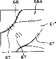
图15所示为一例采用眼球模型的示意图。在图15中,标记62表示眼球模型对应于眼底的一部分,63表示对应于角膜的部分,图中所示为顶角θ为45度时光学元件60压在对应于角膜的部分63上时的状态。物镜19的焦距f为200mm,成像透镜22(32)的焦距f为170mm,并且可变焦度透镜系统20(30)的观察放大率为4.2。当观察放大率为4.2时,消除散光的光学元件61用来消除散光的焦度为-0.017屈光度。Figure 15 is a schematic diagram of an example using an eyeball model. In Fig. 15, mark 62 represents a part of the eyeball model corresponding to the fundus, 63 represents a part corresponding to the cornea, and the figure shows that when the apex angle θ is 45 degrees, the
当不用消除散光的光学元件61时,将会如图7所述的那样产生散光。然而,当用消除散光的光学元件61在一方向上设定焦度来消除散光时,就能如图6所示消除散光。When the astigmatism-eliminating
当观察放大率为6.3时,消除散光的光学元件61的焦度为-0.043屈光度。同样,当观察放大率为10.5时,消除散光的光学元件61的焦度为-0.11屈光度,当观察放大率为16时,消除散光的光学元件61的焦度为-0.284屈光度,当观察放大率为21时,消除散光的光学元件61的焦度为-0.445屈光度。When the viewing magnification is 6.3, the focal power of the
图16为本发明观察装置的一改进实施例。在该改进实施例中,消除散光的光学元件61布置在物镜19和可变焦度透镜系统20(30)之间。Fig. 16 is an improved embodiment of the observation device of the present invention. In this modified embodiment, an astigmatism-reducing
这样,当消除散光的光学元件61布置在物镜19和可变焦度透镜系统20(30)之间的一个位置以便转换来自眼底Er的平行反射光束时,在没有受到可变焦度的影响并且没有根据放大率改变消除散光的光学元件61焦度的情况下,可将散光消除,从而使操作更为方便。In this way, when the
此外,当消除散光的光学元件61布置在物镜19和可变焦度透镜系统20(30)之间的一个位置以便转换来自眼底Er的平行反射光束时,或者布置在一个位置以便转换通过可变焦度透镜系统20(30)到成像透镜22(33)而得到的平行反射光束时,无论这对可变柱面透镜61A和61B之间的距离怎样,均可将散光消除,因此消除散光的操作更为容易。注意,消除散光的光学元件可布置光学观察系统从物镜19到目镜26(36)之间的观察路径的任一位置。Furthermore, when the astigmatism-eliminating
图17所示为本发明观察装置实施例2中光学系统的示意图。该观察装置包括一个图像处理设备64和可变柱面透镜旋转装置65,后者构成用来自动改变散光焦度量的装置的一部分。该可变柱面透镜旋转装置65包括例如一个步进电机。将TV摄像机53的图像输出输入到图像处理设备64,然后将图像数据输出到一台监视器TV66上。图像处理设备64具有一个用来校正散光的分析程序。Fig. 17 is a schematic diagram of the optical system in Embodiment 2 of the observation device of the present invention. The viewing arrangement comprises an
如图18所示,眼底周围部分Er’的眼底图像Er”显示在监视器TV66的屏幕66A上。如图所示,当产生散光时,会出现图像67的浮动(flow)。例如血管68的轮廓线会出现浮动。图像处理设备64提取血管68的图像并将一个驱动信号输送给可变柱面透镜旋转装置65。该可变柱面透镜旋转装置65沿着一个与轮廓线的浮动相对应的方向一体转动可变柱面透镜61A和61B。As shown in FIG. 18, the fundus image Er" of the part Er' around the fundus is displayed on the
下一步,将其中一个可变柱面透镜61A或61B的母线轴固定在该方向上。可变柱面透镜旋转装置65根据轮廓线图像中浮动的大小相对地旋转另一个可变柱面透镜61A或61B。这样,就可将消除散光的光学元件61设定在一个消除散光的屈光度上。然后,如图19所示,例如,表示血管68轮廓线的图像的浮动值就变小了。如图19所示,当得到的眼底图像中仍存在散光时,图像处理设备64再次提取血管68的图像并将一驱动信号输送给可变柱面透镜旋转装置65。该可变柱面透镜旋转装置65再次根据轮廓线图像中浮动值绕观察光轴相对转动可变柱面透镜从而设定一个屈光度以便消除散光。Next, fix the generatrix axis of one of the variable
用来自动改变散光焦度量的装置使可变柱面透镜相对转动一对可变柱面透镜61A或61B直到散光变为预定值或更小。此外,基于计算结果校正透镜会产生正的或负的焦度。The means for automatically changing the focal amount of astigmatism makes the variable cylindrical lenses relatively rotate the pair of variable
在实施例2中,即使利用顶角θ不同的光学元件60来改变眼底周围部分Er’的观察区域,也能对散光自动进行校正,从而获得眼底周围部分Er’的清晰图像。In Embodiment 2, even if the observation area of the fundus peripheral part Er' is changed by using the
图20为本发明观察装置实施例3的光学系统的示意图。这里观察装置包括有一个存贮器69。Fig. 20 is a schematic diagram of the optical system of
存贮器69将焦度量作为校正值保存起来。例如,将顶角θ为45度的光学元件60压在对应于角膜的部分63上时,其将-0.017屈光度作为消除散光的光学元件61所需的焦度量保存下来,此时观察放大率设定到4.2。同样,在观察放大率设定到6.3时,将-0.043屈光度保存为消除散光的光学元件61所需的焦度量;在观察放大率设定到10.5时,将-0.11屈光度保存为消除散光的光学元件61所需的焦度量;在观察放大率设定到10.5时,将0.284屈光度保存为消除散光的光学元件61所需的焦度量;在观察放大率设定到21时,将-0.445屈光度保存为消除散光的光学元件61所需的焦度量。The memory 69 stores the focal amount as a correction value. For example, when the
这里保存在存贮器69中的校正值用作具有参照顶角θ的光学元件60在不同观察放大率时的校正值。当压在手术眼球E上的光学元件的顶角不同于光学元件60的参考顶角θ时,图像处理设备64还包括一个用来计算消除散光所需焦度量(校正量)的计算程序。The correction values stored in the memory 69 here are used as correction values at different observation magnifications for the
当压在手术眼球E上的光学元件的顶角不同于光学元件60的参考顶角θ时,操作者在观察屏幕66A的同时首先是使消除散光的光学元件61绕观察光轴O1和O2旋转,从而设定消除散光的焦度量。When the apex angle of the optical element pressed on the surgical eyeball E is different from the reference apex angle θ of the
例如,当把顶角θ为30度的光学元件60压在手术眼球E上时,就需要焦度量为-0.05屈光度的消除散光的光学元件61来消除散光,并且观察放大率为10.5。For example, when the
当操作者改变观察放大率,例如从10.5变到21时,图像处理设备64就从存贮器69读出一个校正值-0.11和一个校正值-0.445,前者是具有参考顶角θ的光学元件60在观察放大率为10.5时的校正值;后者是具有参考顶角θ的光学元件60在观察放大率为21时的校正值。然后图像处理设备64根据读取的数据对应于观察放大率为10.5时校正值计算出一个校正系数。这里,该校正系数大约为4。When the operator changes the observation magnification, for example, from 10.5 to 21, the
图像处理设备64根据该校正系数计算出把顶角θ为30度的光学元件60压在手术眼球E上并且观察放大率设定为21时消除散光的光学元件61所需的焦度量。The
可变柱面透镜旋转装置65根据计算出的校正量相对地旋转消除散光的光学元件61。这里,校正系数大约为4倍。这样,消除散光的光学元件61旋转以使消除散光的光学元件61的焦度变为-0.2屈光度。The variable cylindrical lens rotating device 65 relatively rotates the astigmatism-eliminating
根据实施例3,一旦对应于其顶角不同于参考顶角的棱镜的观察放大率的校正量被确定出,那么就可根据存贮器69中保存的屈光量计算出对应其它观察放大率焦度量。According to
因此,根据实施例3就能快速地对散光进行校正。Therefore, according to
实施例4Example 4
图21和22所示为本发明观察装置的实施例4,其中每一个光学观察系统13a和13b均带有一个消除色差的光学元件70。21 and 22 show Embodiment 4 of the observation device of the present invention, wherein each
在实施例4中,在物镜19和可变焦度透镜系统20(30)之间的观察路径上具有消除色差的光学元件70(70),该观察路径用来将反射光束以平行光束从手术眼球E的眼底Er导引到可变焦度透镜系统20。In Embodiment 4, there is an optical element 70 (70) for eliminating chromatic aberration on the viewing path between the
如图23和24所示,这里的消除色差的光学元件70由一对可变棱镜70A和70B构成。As shown in FIGS. 23 and 24, the chromatic aberration canceling
可变棱镜70A由棱镜71a和71b粘接而成,可变棱镜70B由棱镜71c和71d粘接而成。棱镜71a和71b以及棱镜71c和71d对于基础波长(d线)具有相同的折射系数“nd”。棱镜71a的色散ν小于71b的色散ν。棱镜71d的色散ν小于棱镜71c的色散ν。这里,可变棱镜70A和70B具同相同的结构。The
棱镜折射的方向会产生色差。图22中展示出一种状态,该状态中来自附图后面的反射光束经(棱镜)光学元件60折射后导向物镜19。这里,可以看到:由具有R、G和B波长的光束由光学元件60相互分开。此时,通过旋转来调整消除色差的光学元件70从而使相应的光束R’、G’和B’在穿过消除色差的光学元件70时变为平行光束,这样就能将由光学元件60的折射作用产生的色差消除。The direction of prism refraction produces chromatic aberration. A state is shown in FIG. 22 in which the reflected light beam from the rear of the figure is refracted by the (prism)
因此,如图25所示,将消除散光的光学元件61布置在可变焦度透镜系统20(30)和目镜26(36)之间,同时将71布置在物镜19和可变焦度透镜系统20(30)之间。然后,当使用消除散光的光学元件61时,图9所示的散光点像就能校正为图10所示没有散光只有色差的点像。下一步,当使用消除色差的光学元件70来校正色差时,就能获得消除散光和色差的点像Q,如图8所示。Therefore, as shown in FIG. 25, the
实施例5Example 5
图26为本发明观察装置实施例5的光学系统。这里的图像处理设备64包括一个校正程序,其作为校正装置对在光学元件60压在手术眼球E上时产生的色差进行数字分析并进行校正。Fig. 26 is the optical system of Embodiment 5 of the observation device of the present invention. The
如图27所示,当出现色差时,白色的点像Q被分离成三种颜色R、G和B,从而在监视器TV66的监视屏66a上获得点像R’、G’和B’。As shown in FIG. 27, when a color difference occurs, the white point image Q is separated into three colors R, G, and B, thereby obtaining point images R', G', and B' on the monitor screen 66a of the monitor TV66.
图27中所示图像被分成不同的层——R层、G层和B层。将点像Q相应于每一层的像素地址都保存下来。图像处理设备64进行叠加处理例如,如图28所示G层保存点像G’的地址Xi、Yj;如图29所示R层保存点像R’的地址Xi、Yi+y;如图30所示B层保存点像B’的地址Xi、Yj-y。The image shown in Fig. 27 is divided into different layers - R layer, G layer and B layer. Save the pixel address of point image Q corresponding to each layer. The
由此,将图像分离成R、G和B后而在图像接收元件上获得的点像可在一点上进行数字合成并进行色差校正,即使光学观察系统13a和13b上没有消除散光的棱镜,如图31所示,也可用软件进行。Thus, the point images obtained on the image receiving element after separating the images into R, G, and B can be digitally synthesized at one point and corrected for chromatic aberration even if there are no astigmatism-removing prisms on the
实施例6Example 6
图32所示为本发明观察装置实施例6的光学系统。这里,用来将图案图像(pattem image)投射到眼底Er的光学投影系统72布置在可变焦度透镜系统20(30)和消除散光的光学元件61之间。每一个光学投影系统72(图32)都由圆形图案板(pattern plate)73、投射透镜74和单向透镜75构成。圆形图案经可变焦度透镜系统20和物镜19导引到光学元件60并经光学元件60折射后导向眼底Er的眼底周围部分Er’。Fig. 32 shows the optical system of Embodiment 6 of the observation device of the present invention. Here, an optical projection system 72 for projecting a pattern image to the fundus Er is disposed between the variable focus lens system 20 (30) and the astigmatism-removing
如图33所示,眼底周围部分Er’上形成圆形图案图像76。当图像接收元件53a在消除散光的光学元件61不具有焦度的情况下接收圆形图案图像时,如图34所示,由于散光的作用将形成带有浮动图像77的圆形图案图像78。As shown in Fig. 33, a
图像处理设备64(图32)具有分析处理装置以便对圆形图案图像78进行分析,该图像处理设备64根据圆形图案图像77的浮动计算出校正量,并根据计算结果将一驱动信号输出给可变柱面透镜的旋转装置65。可变柱面透镜的旋转装置65响应于驱动信号驱动消除散光的光学元件61从而消除散光。The image processing device 64 (Fig. 32) has an analysis processing device so that the circular pattern image 78 is analyzed, and the
根据实施例6,散光量可根据已知的圆形图像计算出来。因此,能够精确地确定出散光的多少。According to Embodiment 6, the amount of astigmatism can be calculated from a known circular image. Therefore, the amount of astigmatism can be accurately determined.
如上所述,本发明前述的实施例以观察装置实例的形式描述了这种手术显微镜。然而,本发明并不限于这些,其还可应用于狭裂隙灯显微镜和其它眼科观察装置。As mentioned above, the foregoing embodiments of the present invention describe such a surgical microscope as an example of an observation device. However, the present invention is not limited to these, and it is also applicable to slit lamp microscopes and other ophthalmic observation devices.
实施例7Example 7
图35所示本发明观察装置实施例7的光学结构图。在图35中,附图标记80表示一种已知的光学照射系统,其用来将治疗用的激光照射到眼底Er。来自光学照射系统80的治疗用激光被光学元件(未示出)转换成平行光束、经棱镜18反射并导向物镜19。Fig. 35 shows the optical structure diagram of Embodiment 7 of the observation device of the present invention. In FIG. 35,
用来消除散光的光学元件81布置在物镜19和棱镜18之间,该散光是在把光学元件60压在手术眼球E上然后将治疗用的激光通过光学元件60照射到眼底Er时而引起的。与实施例1一样,消除散光的光学元件81由可变柱面透镜81A和81B以及校正透镜81C构成。可变柱面透镜81A和81B的散光校正量也可通过校正量的软件处理而进行自动校正。An
在用这种结构对眼底Er进行激光治疗时,压在手术眼球E上的光学元件60所产生的散光将被消除。When laser treatment is performed on the fundus Er with this structure, the astigmatism generated by the
本发明的第一到九方面均能消除当接触棱镜压在手术眼球上以便观察眼底周围部分时棱镜所产生的散光。另外,即使激光照射光学系统不与物镜19共同使用,通过考虑激光的照射角度也能够进行照射消除散光。The first to ninth aspects of the present invention all eliminate astigmatism generated by the contact prism when the contact prism is pressed against the operated eyeball to observe the portion around the fundus. In addition, even if the laser irradiation optical system is not used together with the
特别是根据本发明的第二和第三方面,有一个消除散光的光学元件布置在光学观察系统的观察路径上,通过该元件的反射光束将被平行转换,因此能够轻易地将散光消除。In particular, according to the second and third aspects of the present invention, there is an astigmatism-removing optical element arranged on the observation path of the optical observation system, and the reflected light beam passing through the element will be parallel-transformed, so that the astigmatism can be easily eliminated.
更为特别的是根据本发明的第三方面,无论观察放大率如何变化均能消除散光,从而使操作更为方便。More particularly, according to the third aspect of the present invention, no matter how the observation magnification changes, astigmatism can be eliminated, thereby making the operation more convenient.
还有,根据本发明的第五到第八方面,能够自动消除散光,从而使用起来更为方便。Also, according to the fifth to eighth aspects of the present invention, astigmatism can be eliminated automatically, so that it is more convenient to use.
特别是根据本发明的第六和第七方面,可通过图像分析来对散光进行自动校正,从而使操作更为方便。Especially according to the sixth and seventh aspects of the present invention, astigmatism can be automatically corrected through image analysis, thereby making the operation more convenient.
更为特别的是根据本发明的第七方面,可将已知形状的图案投射到眼底而进行散光分析。从而能使分析处理更为精确。More particularly, according to the seventh aspect of the present invention, a pattern of a known shape can be projected onto the fundus for astigmatism analysis. Thereby, the analysis processing can be made more precise.
还有,根据本发明的第八方面,即使压在手术眼球上的接触棱镜的顶角不同于参考顶角,也能快速地校正散光。Also, according to the eighth aspect of the present invention, even if the apex angle of the contact prism pressed on the operated eyeball is different from the reference apex angle, astigmatism can be quickly corrected.
根据本发明的第九方面,能同时消除散光和色差。According to the ninth aspect of the present invention, both astigmatism and chromatic aberration can be eliminated.
本发明的第十到十二方面均能消除接触棱镜压在手术眼球上以便观察眼底周围部分时所产生的散光。The tenth to twelfth aspects of the present invention all eliminate astigmatism generated when the contact prism is pressed against the operated eyeball to observe the portion around the fundus.
特别是根据本发明第十一和第十二方面,有一个消除色差的光学元件布置在光学观察系统的观察路径上,通过该元件的反射光束将被平行转换,因此能够轻易地将色差消除。In particular, according to the eleventh and twelfth aspects of the present invention, there is an optical element for eliminating chromatic aberration arranged on the observation path of the optical observation system, and the reflected light beam passing through the element will be converted in parallel, so that chromatic aberration can be easily eliminated.
根据本发明的第十三方面,即使在光学观察系统的观察路径上没有布置消除色差的光学元件,也能通过软件处理来对色差进行处理。此外,即使不改变光学观察系统的结构,也能消除色差。According to the thirteenth aspect of the present invention, even if no optical element for eliminating chromatic aberration is disposed on the observation path of the optical observation system, chromatic aberration can be processed by software processing. In addition, chromatic aberration can be eliminated without changing the structure of the optical observation system.
根据本发明的第十四方面,能够消除散光从而使治疗用激光照射到眼底。According to the fourteenth aspect of the present invention, it is possible to eliminate astigmatism so that the laser light for treatment can be irradiated to the fundus.
Claims (14)
Applications Claiming Priority (2)
| Application Number | Priority Date | Filing Date | Title |
|---|---|---|---|
| JP2001371536A JP3856691B2 (en) | 2001-12-05 | 2001-12-05 | Observation device |
| JP2001371536 | 2001-12-05 |
Publications (2)
| Publication Number | Publication Date |
|---|---|
| CN1423150A true CN1423150A (en) | 2003-06-11 |
| CN1333282C CN1333282C (en) | 2007-08-22 |
Family
ID=19180564
Family Applications (1)
| Application Number | Title | Priority Date | Filing Date |
|---|---|---|---|
| CNB021538859A Expired - Fee Related CN1333282C (en) | 2001-12-05 | 2002-12-04 | Observation device |
Country Status (6)
| Country | Link |
|---|---|
| US (1) | US6726326B2 (en) |
| EP (1) | EP1321095B1 (en) |
| JP (1) | JP3856691B2 (en) |
| CN (1) | CN1333282C (en) |
| AT (1) | ATE364346T1 (en) |
| DE (1) | DE60220630T2 (en) |
Cited By (8)
| Publication number | Priority date | Publication date | Assignee | Title |
|---|---|---|---|---|
| CN103767673A (en) * | 2012-10-18 | 2014-05-07 | 佳能株式会社 | Ophthalmologic apparatus |
| CN103926679A (en) * | 2013-01-11 | 2014-07-16 | 晋弘科技股份有限公司 | Lens module and fundus camera |
| CN102272651B (en) * | 2008-11-07 | 2014-09-24 | 汉密尔顿-索恩公司 | Modular objective assembly |
| CN105496353A (en) * | 2016-01-29 | 2016-04-20 | 苏州兆乘软件有限公司 | Microscope capable of being used for observing fundus oculi |
| CN106389004A (en) * | 2015-07-29 | 2017-02-15 | 广东福地新视野光电技术有限公司 | Laser adapter with continuously adjustable light spots and fundus laser therapeutic instrument |
| CN107405069A (en) * | 2015-04-30 | 2017-11-28 | 诺华股份有限公司 | Ophthalmic visualization device, system and method |
| CN108523838A (en) * | 2017-02-08 | 2018-09-14 | 欧视博公司 | The device and method of contactless inspection for eyes |
| CN113230027A (en) * | 2016-07-18 | 2021-08-10 | 卡尔蔡司医疗技术股份公司 | System for ophthalmological treatment by means of tissue treatment by means of nonlinear interaction |
Families Citing this family (11)
| Publication number | Priority date | Publication date | Assignee | Title |
|---|---|---|---|---|
| JP4417035B2 (en) | 2003-06-09 | 2010-02-17 | 株式会社トプコン | Observation device |
| US7290880B1 (en) | 2005-07-27 | 2007-11-06 | Visionsense Ltd. | System and method for producing a stereoscopic image of an eye fundus |
| US8506083B2 (en) * | 2011-06-06 | 2013-08-13 | Clarity Medical Systems, Inc. | Compact wavefront sensor module and its attachment to or integration with an ophthalmic instrument |
| US7896498B2 (en) * | 2009-03-30 | 2011-03-01 | Ottawa Hospital Research Institute | Apparatus and method for optical measurements |
| JP2013027536A (en) * | 2011-07-28 | 2013-02-07 | Topcon Corp | Microscope for ophthalmologic surgery |
| WO2015168812A1 (en) | 2014-05-08 | 2015-11-12 | Mimo Ag | Optical coherence tomography imaging device for imaging a retina of a human subject |
| CN104614848A (en) * | 2015-02-11 | 2015-05-13 | 衡雪源 | Neurosurgical multi-user electronic surgery microscope |
| JP6423104B2 (en) | 2015-09-17 | 2018-11-14 | 富士フイルム株式会社 | Lens device, camera system, and aberration correction unit |
| DE102017105580A1 (en) | 2016-11-04 | 2018-05-09 | Carl Zeiss Meditec Ag | surgical microscope |
| JP7263726B2 (en) * | 2018-09-28 | 2023-04-25 | 株式会社ニデック | Ophthalmic laser therapy device and ophthalmic laser control program |
| US12048484B2 (en) | 2021-04-21 | 2024-07-30 | Amo Development, Llc | Compact autocylinder compensation module for autorefractor and autorefractor with autocylinder compensation module |
Family Cites Families (29)
| Publication number | Priority date | Publication date | Assignee | Title |
|---|---|---|---|---|
| DE2202120A1 (en) * | 1972-01-18 | 1973-07-26 | Zeiss Carl Fa | OPTICAL DEVICE FOR GENERATING COAGULATIONS, PREFERABLY ON THE RETINES OF ONE EYE |
| US3915564A (en) * | 1974-09-12 | 1975-10-28 | Zeiss Stiftung | Retinal image-display system |
| US4065208A (en) * | 1974-10-29 | 1977-12-27 | Currey Thomas A | Ophthalmoscope |
| DE3001244A1 (en) * | 1979-01-16 | 1980-07-24 | Canon Kk | FOCUSING SYSTEM FOR A BASIC EYE CAMERA |
| JPS59174144A (en) * | 1983-03-22 | 1984-10-02 | キヤノン株式会社 | Ophthalmic photographing apparatus |
| US4601550A (en) * | 1983-08-08 | 1986-07-22 | Tokyo Kogaku Kikai Kabushiki Kaisha | Stereo-microscope with a common objective lens system |
| DE3546915C2 (en) * | 1984-04-27 | 1999-08-26 | Canon Kk | Single objective stereo microscope |
| US4634241A (en) * | 1984-04-27 | 1987-01-06 | Canon Kabushiki Kaisha | Stereoscopic microscope |
| US4568157A (en) * | 1984-07-11 | 1986-02-04 | Board Of Regents, The University Of Texas System | Goniotomy lens |
| US4906078A (en) * | 1987-08-12 | 1990-03-06 | Olympus Optical Co., Ltd. | Variable magnification viewfinder |
| KR910004795B1 (en) * | 1988-12-27 | 1991-07-13 | 정수철 | Parking garage with mechanical means |
| US5098426A (en) * | 1989-02-06 | 1992-03-24 | Phoenix Laser Systems, Inc. | Method and apparatus for precision laser surgery |
| JPH0381879A (en) * | 1989-08-24 | 1991-04-08 | Canon Inc | Medical image processor |
| JPH0343623U (en) * | 1989-09-06 | 1991-04-24 | ||
| US5490849A (en) * | 1990-07-13 | 1996-02-13 | Smith; Robert F. | Uniform-radiation caustic surface for photoablation |
| JP2554219Y2 (en) * | 1991-08-30 | 1997-11-17 | 京都コンタクトレンズ株式会社 | Contact lenses for intraocular vitreous surgery |
| JPH06142052A (en) * | 1992-11-05 | 1994-05-24 | Canon Inc | Optometric apparatus |
| JP3298212B2 (en) * | 1993-03-12 | 2002-07-02 | 株式会社ニコン | Position detection method and apparatus, exposure method, projection exposure apparatus, and element manufacturing method |
| JP3165291B2 (en) * | 1993-06-30 | 2001-05-14 | 株式会社ニデック | Light therapy equipment |
| US6304723B1 (en) * | 1994-10-11 | 2001-10-16 | Canon Kk | Retinal camera |
| US6033396A (en) * | 1995-11-06 | 2000-03-07 | Huang; David | Apparatus and method for performing laser thermal keratoplasty with minimized regression |
| JPH09251133A (en) * | 1996-03-14 | 1997-09-22 | Nikon Corp | Wide visual field eyepiece |
| JP3673049B2 (en) * | 1997-02-04 | 2005-07-20 | オリンパス株式会社 | Confocal microscope |
| JPH10254053A (en) * | 1997-03-07 | 1998-09-25 | Mitsubishi Electric Corp | Image pickup device |
| CN1289027C (en) * | 1997-04-01 | 2006-12-13 | 约翰斯霍普金斯大学 | A system for imaging ocular fundus semi-automatically at high resolution and wide field |
| JPH11211979A (en) * | 1998-01-27 | 1999-08-06 | Matsushita Electric Ind Co Ltd | Projection image correcting lens, projection lens device, and projection type display device |
| JP2000121942A (en) * | 1998-10-16 | 2000-04-28 | Olympus Optical Co Ltd | Zoom lens |
| US6120147A (en) * | 1999-03-17 | 2000-09-19 | Dutch Ophthalmic Research Center International Bv | Vitrectomy lens |
| JP2001108906A (en) * | 1999-10-01 | 2001-04-20 | Topcon Corp | Surgical microscope |
-
2001
- 2001-12-05 JP JP2001371536A patent/JP3856691B2/en not_active Expired - Fee Related
-
2002
- 2002-12-04 US US10/309,309 patent/US6726326B2/en not_active Expired - Fee Related
- 2002-12-04 EP EP02026940A patent/EP1321095B1/en not_active Expired - Lifetime
- 2002-12-04 DE DE60220630T patent/DE60220630T2/en not_active Expired - Lifetime
- 2002-12-04 CN CNB021538859A patent/CN1333282C/en not_active Expired - Fee Related
- 2002-12-04 AT AT02026940T patent/ATE364346T1/en not_active IP Right Cessation
Cited By (11)
| Publication number | Priority date | Publication date | Assignee | Title |
|---|---|---|---|---|
| CN102272651B (en) * | 2008-11-07 | 2014-09-24 | 汉密尔顿-索恩公司 | Modular objective assembly |
| CN103767673A (en) * | 2012-10-18 | 2014-05-07 | 佳能株式会社 | Ophthalmologic apparatus |
| CN103926679A (en) * | 2013-01-11 | 2014-07-16 | 晋弘科技股份有限公司 | Lens module and fundus camera |
| CN103926679B (en) * | 2013-01-11 | 2017-05-10 | 晋弘科技股份有限公司 | Lens module and fundus camera |
| CN107405069A (en) * | 2015-04-30 | 2017-11-28 | 诺华股份有限公司 | Ophthalmic visualization device, system and method |
| CN106389004A (en) * | 2015-07-29 | 2017-02-15 | 广东福地新视野光电技术有限公司 | Laser adapter with continuously adjustable light spots and fundus laser therapeutic instrument |
| CN106389004B (en) * | 2015-07-29 | 2018-12-07 | 广东福地新视野光电技术有限公司 | Laser adapter with continuously adjustable light spots and fundus laser therapeutic instrument |
| CN105496353A (en) * | 2016-01-29 | 2016-04-20 | 苏州兆乘软件有限公司 | Microscope capable of being used for observing fundus oculi |
| CN113230027A (en) * | 2016-07-18 | 2021-08-10 | 卡尔蔡司医疗技术股份公司 | System for ophthalmological treatment by means of tissue treatment by means of nonlinear interaction |
| CN108523838A (en) * | 2017-02-08 | 2018-09-14 | 欧视博公司 | The device and method of contactless inspection for eyes |
| CN108523838B (en) * | 2017-02-08 | 2020-06-16 | 欧视博公司 | Apparatus and method for non-contact examination of an eye |
Also Published As
| Publication number | Publication date |
|---|---|
| US20030128333A1 (en) | 2003-07-10 |
| CN1333282C (en) | 2007-08-22 |
| DE60220630T2 (en) | 2008-02-14 |
| JP2003172876A (en) | 2003-06-20 |
| EP1321095A2 (en) | 2003-06-25 |
| DE60220630D1 (en) | 2007-07-26 |
| JP3856691B2 (en) | 2006-12-13 |
| EP1321095A3 (en) | 2004-03-17 |
| ATE364346T1 (en) | 2007-07-15 |
| US6726326B2 (en) | 2004-04-27 |
| EP1321095B1 (en) | 2007-06-13 |
Similar Documents
| Publication | Publication Date | Title |
|---|---|---|
| CN1423150A (en) | Observation device | |
| JP3225358B2 (en) | Contact lens device for indirect ophthalmoscope for diagnosis | |
| JP6462596B2 (en) | Automatic imager alignment | |
| JP4417035B2 (en) | Observation device | |
| CN1678235A (en) | Portable Ophthalmic Devices and Ophthalmic Systems | |
| CN1838909A (en) | Ophthalmic camera, ophthalmic camera adapter, and method for detecting hemoglobin and glucose levels in a patient | |
| CN1868397A (en) | Ophthalmic apparatus | |
| JP2008154727A (en) | Ophthalmic equipment | |
| CN1523393A (en) | surgical microscope | |
| JP2015500111A (en) | Automatic image optimization system, especially for stereomicroscopes | |
| CN1388895A (en) | Method for measuring refractive power and apparatus therefor | |
| CN110074753B (en) | Fundus camera | |
| JP2005118561A (en) | Lighting and observing system | |
| CN1834719A (en) | Microscope for operation | |
| CN1921983A (en) | Method for manually centering an ophthalmic lens in a centering/locking device and associated centering/locking device | |
| JP2010131060A (en) | Eye measuring apparatus, eye measuring method and program | |
| CN1278661C (en) | Keratectomy data determining device and keratectomy data determining program | |
| JP2005034285A (en) | Surgical microscope and observation prism | |
| KR101348939B1 (en) | retinal camera | |
| JP6043120B2 (en) | Objective refraction wavefront aberration measuring device | |
| JP2020178980A (en) | Ophthalmographic apparatus and wide-angle lens attachment | |
| CN117460447A (en) | Fundus information acquiring method and fundus information acquiring apparatus | |
| JP6937536B1 (en) | Fundus photography device | |
| JP7089823B1 (en) | Image projection device, visual test device, and fundus photography device | |
| JP6296721B2 (en) | Ophthalmic imaging apparatus and control method thereof |
Legal Events
| Date | Code | Title | Description |
|---|---|---|---|
| C06 | Publication | ||
| PB01 | Publication | ||
| C10 | Entry into substantive examination | ||
| SE01 | Entry into force of request for substantive examination | ||
| C14 | Grant of patent or utility model | ||
| GR01 | Patent grant | ||
| C17 | Cessation of patent right | ||
| CF01 | Termination of patent right due to non-payment of annual fee |
Granted publication date: 20070822 Termination date: 20111204 |