Description of drawings
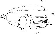
Fig. 1 is the stereoscopic figure of the dust catcher of the present invention the 1st embodiment.
Fig. 2 (a) is near the phantom of the structure of exhaust outlet of this dust catcher of expression.
Fig. 2 (b) is the B portion enlarged drawing of Fig. 2 (a).
Fig. 3 is the integrally-built cutaway view of this dust catcher.
Fig. 4 is near the phantom of the structure exhaust outlet of dust catcher of expression the present invention the 2nd embodiment.
Fig. 5 (a) is the C portion enlarged drawing of Fig. 4.
Fig. 5 (b) is the part amplification view of other structures of the vent cap of this dust catcher of expression.
Fig. 6 is the partially cut-away side view that the rear portion is arranged on ground erectility of this dust catcher of expression.
Fig. 7 is the D portion enlarged drawing of Fig. 6.
Fig. 8 is near the phantom of the structure exhaust outlet of dust catcher of expression the present invention the 3rd embodiment.
Fig. 9 (a) is near the phantom of the structure exhaust outlet of the exhaust outlet lid of the dust catcher of expression the present invention the 4th embodiment when being in closed condition.
Fig. 9 (b) is the diagrammatic sketch of the vent cap of pie graph 9 (a) when being in open mode.
Figure 10 (a) is near the phantom of other structures the exhaust outlet of vent cap when being in closed condition of this dust catcher of expression.
Figure 10 (b) is the vent cap that constitutes Figure 10 (a) diagrammatic sketch when being in open mode.
Figure 11 is near the cutaway view of the structure exhaust outlet of dust catcher of expression the present invention the 5th embodiment.
Figure 12 is the stereoscopic figure of the dust catcher of expression the present invention the 6th embodiment.
Figure 13 is the partially cut-away side view of other examples of this dust catcher.
Figure 14 is the phantom of other examples of this dust catcher.
Figure 15 is the F portion enlarged drawing of Figure 14.
Figure 16 is the stereoscopic figure of dust catcher in the past.
Figure 17 is the cutaway view of this dust catcher.
Figure 18 is near the phantom of the structure of exhaust outlet of this dust catcher of expression.
Figure 19 is near the phantom of other structures of the exhaust outlet of this dust catcher of expression.
The specific embodiment
(the 1st embodiment)
Below, in conjunction with Fig. 1 and Fig. 2, the 1st embodiment of the present invention is described.The overall structure of dust catcher since with in the past dust catcher identical Therefore, omited explanation.
Fig. 1 is the stereoscopic figure of the dust catcher of the present invention the 1st embodiment.
Fig. 2 (a) is near the phantom of exhaust outlet of the dust catcher of presentation graphs 1.Fig. 2 (b) is the B portion enlarged drawing in Fig. 2 (a).
As Fig. 1 and Fig. 2 (a) (b) shown in, main body of dust collector 101 has electric blowing machine 120, discharge filter 104, exhaust outlet 101a and is rotatably mounted, covers the vent cap 102 of exhaust outlet 101a around axle 103.When the console switch 151 of flexible pipe 150 ends that are connected with main body 101 was connected, electric blowing machine 120 became operating condition and attracts air.Collected by the dust-collecting filter in the dust storage chamber in electric blowing machine 120 the place aheads (not shown) by the dust that electric blowing machine 120 is attracted with air.Use the dust-collecting filter cleaned air passes, the exhaust outlet 120a from electric blowing machine 120 discharges by electric blowing machine 120, and the exhaust outlet 101a from main body 101 after by discharge filter 104 fine dust contained in the exhaust being filtered again discharges to the outside.At this moment, cover the vent cap 102 of exhaust outlet 101a, be subjected to exhaust fixed blast and the foreign side that is pushed to main body 101 rotates around axle 103, move to the position of 102b, open exhaust outlet 101a.From the exhaust of exhaust outlet 101a discharge, along the parallel earthward or top discharge to the guide part of (by the rear end, being tilted to oblique upper more more) obliquely upward by the rear end.Along with the control of dust quantitative change in the dust storage chamber (not shown) is many, owing to increase by the air-breathing resistance of dust storage chamber, the air-breathing air quantity of electric blowing machine 120 reduces.Along with air-breathing air quantity reduces, reduce owing to pass through the air of the fan (not shown) of electric blowing machine 120, so being subjected to the resistance of air, reduces by fan.The load that is electric blowing machine 120 reduces, and the rotating speed of electric blowing machine 120 increases and the noise increase.But, owing to minimizing, make vent cap 102 utilize the angle of EXO exhaust outlet to reduce by air-breathing air quantity and exhaust air quantity, so can make the Rotation Noise of electric blowing machine 120 be difficult to send, therefore, can obtain the sound that quietly turns round to the outside of main body 101.
The dust catcher of Fig. 3 has: main body 101, flexible pipe 150, prolongation are managed 134, are made at the air suction way 136 of suction fitting 135 to the inspiratory flow of electric blowing machine 120, and make the exhaust channel 137 from the exhaust flow of electric blowing machine 120.The dust that electric blowing machine 120 attracts by air suction way 136 by in the dust-collecting filter 138 that is located in the dust storage chamber (not shown) in electric blowing machine 120 the place aheads collect.With dust-collecting filter 138 cleaned air passes, backflow near the air entry 139 of suction fitting 135 by exhaust channel 137.In main body 101, have: in the exhaust outlet 120a that airtight shape ground is communicated with electric blowing machine 120 and the main body exhaust channel 160 and cover electric blowing machine 120 peripheries lid 121, be formed on the lid 121, make lid 121 inner with the exhaust outlet 121a of main body 101 internal communication, valve body 123 and the drive motor 122 of switching exhaust outlet 121a.Drive motor 122 drives valve body 123 to open and close exhaust outlet 121a.When valve body 123 is opened the exhaust outlet 121a of lid 121, discharge to main body 101 inside by the exhaust behind the electric blowing machine 120.Be provided with vent cap shown in Figure 2 102 at main body 101 rear portions.The pressure at expulsion that increases, causes because of the blast of exhaust when the air quantity of exhaust becomes setting when above, vent cap 102 because of exhaust by position from 102b to the foreign side of main body 101 that release and move to, open exhaust outlet 101a.When valve body 123 is closed the exhaust outlet 121a of lid 121,, backflow near the air entry 139 of suction fitting 135 by lid 121, main body exhaust channel 160 and exhaust channel 137 from the exhaust that the exhaust discharge portion 120a of electric blowing machine 120 discharges.Therefore, do not come the exhaust of autonomous agent 101, vent cap 102 is being closed.
As mentioned above, when exhaust outlet 121a opens, discharge from main body 101, can guarantee enough air-breathing air quantity and obtain high inhalation power by making the many exhausts of air quantity of backflowing of its amount.When exhaust outlet 121a closes, utilize backflowing of exhaust, can obtain not have the quiet running of exhaust, can not produce sweeping of cleaning that dust disperses.And, from main body 101 to the having or not of outside exhaust, be that dust catcher is in the state with high inhalation power or is in the exhaust gas recirculation state, owing to can recognize, so the dust catcher usability of present embodiment is good from the switching of vent cap 102.In addition, in the present embodiment,,, also can obtain to make the synchronized effect of switching of valve body 123 and vent cap 102 by the part of this two part of other connection is set though valve body 123 and vent cap 102 are moved respectively.
(the 2nd embodiment)
Below, in conjunction with Fig. 4-Fig. 7 the 2nd embodiment of the present invention is described.In addition, to omitting its explanation with the identical parts of last embodiment.Fig. 4 is near the phantom of exhaust outlet of the dust catcher of expression the present invention the 2nd embodiment, and Fig. 5 (a) is the C portion enlarged drawing of Fig. 4.
Have discharge filter 104 and exhaust outlet 101a at the rear portion of main body 101.Has the wall 106 that surrounds exhaust outlet 101a in the outside of exhaust outlet 101a.Wall 106 is opening and constitute the exhaust guide part upward.
Shown in Fig. 5 (a), be provided with vent cap 105 rotationally around axle 103, vent cap 105 can open and close the peristome (below, be called the main body exhaust outlet) of wall 106 tops.Axle 103 is installed on the main body 101, and is configured in the below of vent cap 105 the other end.Therefore, the deadweight of vent cap 105 acts on the direction that makes the main body exhaust close.When the blast from the exhaust of exhaust outlet 101a becomes setting when above, vent cap 105 is pushed open upward because of the blast of exhaust, exhaust along wall 106 by the outside top of row to main body 101.Fig. 5 (b) is another structure example of vent cap.Vent cap 105 is housed inside scope inside that wall 106 encloses in the dead astern of exhaust outlet 101a.Fig. 6 represents the rear portion of main body 101 is arranged at ground user mode, and Fig. 7 is the D portion enlarged drawing of Fig. 6.As shown in Figure 7, rear portion 140a, the 140b of main body 101 is arranged on the ground of small space of stair etc.The axle of vent cap 105 103 as shown in Figure 5 owing to be installed on the main body 101 and be configured in the below, the other end of vent cap 105, so even under the state of Fig. 7, the deadweight of vent cap 105 also acts on the direction that makes the main body exhaust close.Because the discharge direction of exhaust is towards the top of main body 101, so can carry out not producing sweeping of cleaning that rubbish disperses because of exhaust.And, because that the stream that surrounds foreign side, the discharge exhaust of exhaust outlet 101a with wall 106 makes is longer, so can make with exhaust by the sound attenuation of the running sound of the electric blowing machine 120 of emitting etc. to main body 101 outsides.In addition, along with the control of dust amount of dust storage chamber (not shown) increases, owing to increase by the air-breathing resistance of dust storage chamber, so the air-breathing air quantity minimizing of electric blowing machine 102.And, along with air-breathing air quantity reduces,,, fan reduces so being subjected to the resistance of air owing to reduce by the air in the fan of electric blowing machine 102.That is to say, the load that electric blowing machine 102 is subjected to reduces, the rotating speed of electric blowing machine 102 increases and noise is uprised, but because by reducing the angle minimizing that air-breathing air quantity, exhaust air quantity and exhaust blast make vent cap 105 open the main body exhaust outlet because of exhaust, so can make the rotation sound of electric blowing machine be difficult for emitting the outside of main body 101.Therefore, can obtain more quiet running sound.
Again because the deadweight of vent cap 105 acts on the direction that makes the main body exhaust close as previously mentioned, so be not with exhaust from the occasion of main body 101 to the operation mode of outside discharge, vent cap 105 is closed condition.Therefore, rear portion 140a, the 140b of main body 101 can be arranged under the ground state of small space of stair etc. and be kept, and can carry out not producing sweeping of cleaning that rubbish disperses because of exhaust.And, can obtain quietly to turn round sound.
(the 3rd embodiment)
Below, in conjunction with Fig. 8 the 4th embodiment of the present invention is described.In addition, the part identical with front embodiment omitted its explanation.
Among Fig. 8, has the wall 106 that surrounds exhaust outlet 101a in the outside of the exhaust outlet 101a of main body 101.Wall 106 is opening upward.The vent cap 105 that opens and closes the peristome of wall 106 tops is configured to and can rotates around axle 103.Vent cap 105 has the aerofoil of being subjected to 105a in the wall 106 of exhaust outlet 101a.Be subjected to aerofoil 105a, when vent cap 105 is opened upward because of exhaust, the rotatory force of vent cap 105 strengthened.Thus, vent cap 105 is opened more upward.Its result, can make the discharge direction of exhaust towards the top of main body 101, and can carry out not producing sweeping of cleaning that rubbish disperses because of exhaust.
(the 4th embodiment)
Below, in conjunction with Fig. 9, Figure 10 the 4th embodiment of the present invention is described.In addition, the part identical with front embodiment omitted its explanation.
The vent cap 108 of Fig. 9 (a) has discharge filter 104 and exhaust guide part 108a.The state of the no exhaust of Fig. 9 (a) expression, exhaust guide part 108a closes the exhaust outlet 101a of main body 101.Fig. 9 (b) expression has the state of exhaust, and the pressure that vent cap 108 is passed through the exhaust of discharge filter 104 pushes and rotates to the direction of exhaust outlet 101a, and exhaust guide part 108a opens exhaust outlet 101a.Exhaust is discharged from by exhaust outlet 101a.The exhaust outlet 101a of the main body 101 of Figure 10 (a) has the 101b of grid portion, and vent cap 110 has the 110a of grid portion.The state of the no exhaust of Figure 10 (a) expression, the 110a of grid portion closes the exhaust outlet 101a of main body 101.Figure 10 (b) expression has the state of exhaust, and the pressure that vent cap 110 is deflated pushes and rotates to foreign side, and the 110a of grid portion opens exhaust outlet 101a.Exhaust is discharged from by the gap 110b between exhaust outlet 101a and the 110a of grid portion.Along with the control of dust amount of dust storage chamber increases, owing to increase by the air-breathing resistance of dust storage chamber, so the air-breathing air quantity minimizing of electric blowing machine 102.And along with air-breathing air quantity reduces, owing to reduce by the air in the fan of electric blowing machine 102, fan reduces because of the resistance that is subjected to air.That is to say that the load that electric blowing machine 102 is subjected to reduces.Though the rotating speed of electric blowing machine 102 increases and noise is increased, but because by reducing the angle minimizing that air-breathing air quantity and exhaust air quantity make vent cap 110 open exhaust outlet 101a because of exhaust, so can make the rotation sound of electric blowing machine 102 be difficult to emit the outside of main body 101.Therefore, can obtain the sound that quietly turns round.
(the 5th embodiment)
Below, in conjunction with Figure 11 the 5th embodiment of the present invention is described.In addition, the part identical with front embodiment omitted its explanation.
Among Figure 11, has the wall 106 that surrounds exhaust outlet 101a in the outside of exhaust outlet 101a.Wall 106 is opening upward.But the vent cap 105 that opens and closes wall 106 top peristomes is configured to winding rotates at the axle 103 of wall 106 sides.Vent cap 105 has the 105b of lid in two sides.Exhaust is flowed between the lid 105b of two sides.Be deflated pushing and when rotating upward, cap 105b is outstanding from the top peristome in vent cap 105, make exhaust flow path form highlyer and exhaust flow path is prolonged than wall 106.Thus, the discharge direction that can make exhaust is towards the top of main body 101, and can carry out not producing sweeping of cleaning that rubbish disperses because of exhaust.Prolong simultaneously the sound attenuation of the running sound that can make electronic air feeder 102 etc. because of exhaust flow path.
(the 6th embodiment)
Below, in conjunction with Figure 12-Figure 15 the 6th embodiment of the present invention is described.In addition, the part identical with front embodiment omitted its explanation.
Among Figure 12, on the exhaust cap 105 at main body 101 rear portions, be provided with the graduation apparatus 105c of the amount of spin of the described vent cap 105 of expression.Figure 13 is arranged on example on main body 101 end faces with vent cap 105.When the control of dust amount of main body 101 increases, suck the minimizing of air quantity and exhaust air quantity and the amount of spin of vent cap 105 is reduced.The user recognizes the scale 105c of exhaust cap 105, just knows the reduction that sucks air quantity, is that rubbish should be abandoned period in the reduction of inhalation power and the dust storage chamber, improves usability.In Figure 14 and Figure 15, be provided with in the dead astern of vent cap 105 by what the blade 111b of the mobile vibration that utilizes exhaust and ventilating part 111a constituted and blow a whistle 111, when because the control of dust amount increases, air-breathing exhaust air quantity reduces the amount of spin of vent cap 105 buy when getting off less, wind speed in the exhaust of 111 internal flows of blowing a whistle increases, make blade 111b vibration, just cause and ring.Thus, the user knows that with sense of hearing the reduction of inhalation power and the rubbish in the dust storage chamber should abandon period, further improves usability.