CN1335040A - Segmented performance monitoring of multi-stage ATM node - Google Patents
Segmented performance monitoring of multi-stage ATM node Download PDFInfo
- Publication number
- CN1335040A CN1335040A CN99816190A CN99816190A CN1335040A CN 1335040 A CN1335040 A CN 1335040A CN 99816190 A CN99816190 A CN 99816190A CN 99816190 A CN99816190 A CN 99816190A CN 1335040 A CN1335040 A CN 1335040A
- Authority
- CN
- China
- Prior art keywords
- cell
- monitoring
- mark
- terminal
- section
- Prior art date
- Legal status (The legal status is an assumption and is not a legal conclusion. Google has not performed a legal analysis and makes no representation as to the accuracy of the status listed.)
- Granted
Links
- 238000012544 monitoring process Methods 0.000 title claims abstract description 151
- 230000004044 response Effects 0.000 claims abstract description 10
- 238000000034 method Methods 0.000 claims description 38
- 230000008569 process Effects 0.000 claims description 6
- 230000004913 activation Effects 0.000 abstract description 14
- 238000012546 transfer Methods 0.000 abstract description 11
- 210000004027 cell Anatomy 0.000 description 249
- 230000005540 biological transmission Effects 0.000 description 14
- 238000010586 diagram Methods 0.000 description 12
- 238000005516 engineering process Methods 0.000 description 11
- 238000006243 chemical reaction Methods 0.000 description 7
- 238000004458 analytical method Methods 0.000 description 5
- 230000002093 peripheral effect Effects 0.000 description 4
- 230000008901 benefit Effects 0.000 description 3
- 230000008859 change Effects 0.000 description 3
- 230000008878 coupling Effects 0.000 description 3
- 238000010168 coupling process Methods 0.000 description 3
- 238000005859 coupling reaction Methods 0.000 description 3
- 230000000694 effects Effects 0.000 description 3
- 230000011218 segmentation Effects 0.000 description 3
- 238000012360 testing method Methods 0.000 description 3
- 239000004744 fabric Substances 0.000 description 2
- 238000003780 insertion Methods 0.000 description 2
- 230000037431 insertion Effects 0.000 description 2
- 238000012423 maintenance Methods 0.000 description 2
- 230000000644 propagated effect Effects 0.000 description 2
- 210000004128 D cell Anatomy 0.000 description 1
- 230000009471 action Effects 0.000 description 1
- 230000003321 amplification Effects 0.000 description 1
- 230000000712 assembly Effects 0.000 description 1
- 238000000429 assembly Methods 0.000 description 1
- 230000015572 biosynthetic process Effects 0.000 description 1
- 230000003139 buffering effect Effects 0.000 description 1
- 230000015556 catabolic process Effects 0.000 description 1
- 230000006727 cell loss Effects 0.000 description 1
- 125000004122 cyclic group Chemical group 0.000 description 1
- 230000002950 deficient Effects 0.000 description 1
- 238000006731 degradation reaction Methods 0.000 description 1
- 238000012217 deletion Methods 0.000 description 1
- 230000037430 deletion Effects 0.000 description 1
- 238000011161 development Methods 0.000 description 1
- 230000018109 developmental process Effects 0.000 description 1
- 238000013154 diagnostic monitoring Methods 0.000 description 1
- 238000006073 displacement reaction Methods 0.000 description 1
- 230000002349 favourable effect Effects 0.000 description 1
- 238000005755 formation reaction Methods 0.000 description 1
- 238000013507 mapping Methods 0.000 description 1
- 238000010295 mobile communication Methods 0.000 description 1
- 238000012986 modification Methods 0.000 description 1
- 230000004048 modification Effects 0.000 description 1
- 238000003199 nucleic acid amplification method Methods 0.000 description 1
- 230000011664 signaling Effects 0.000 description 1
Images


Classifications
-
- H—ELECTRICITY
- H04—ELECTRIC COMMUNICATION TECHNIQUE
- H04L—TRANSMISSION OF DIGITAL INFORMATION, e.g. TELEGRAPHIC COMMUNICATION
- H04L49/00—Packet switching elements
- H04L49/30—Peripheral units, e.g. input or output ports
- H04L49/3081—ATM peripheral units, e.g. policing, insertion or extraction
-
- H—ELECTRICITY
- H04—ELECTRIC COMMUNICATION TECHNIQUE
- H04L—TRANSMISSION OF DIGITAL INFORMATION, e.g. TELEGRAPHIC COMMUNICATION
- H04L12/00—Data switching networks
- H04L12/54—Store-and-forward switching systems
- H04L12/56—Packet switching systems
- H04L12/5601—Transfer mode dependent, e.g. ATM
-
- H—ELECTRICITY
- H04—ELECTRIC COMMUNICATION TECHNIQUE
- H04L—TRANSMISSION OF DIGITAL INFORMATION, e.g. TELEGRAPHIC COMMUNICATION
- H04L41/00—Arrangements for maintenance, administration or management of data switching networks, e.g. of packet switching networks
- H04L41/06—Management of faults, events, alarms or notifications
- H04L41/0695—Management of faults, events, alarms or notifications the faulty arrangement being the maintenance, administration or management system
-
- H—ELECTRICITY
- H04—ELECTRIC COMMUNICATION TECHNIQUE
- H04L—TRANSMISSION OF DIGITAL INFORMATION, e.g. TELEGRAPHIC COMMUNICATION
- H04L49/00—Packet switching elements
- H04L49/10—Packet switching elements characterised by the switching fabric construction
- H04L49/104—Asynchronous transfer mode [ATM] switching fabrics
- H04L49/105—ATM switching elements
- H04L49/106—ATM switching elements using space switching, e.g. crossbar or matrix
-
- H—ELECTRICITY
- H04—ELECTRIC COMMUNICATION TECHNIQUE
- H04L—TRANSMISSION OF DIGITAL INFORMATION, e.g. TELEGRAPHIC COMMUNICATION
- H04L49/00—Packet switching elements
- H04L49/15—Interconnection of switching modules
- H04L49/1553—Interconnection of ATM switching modules, e.g. ATM switching fabrics
-
- H—ELECTRICITY
- H04—ELECTRIC COMMUNICATION TECHNIQUE
- H04L—TRANSMISSION OF DIGITAL INFORMATION, e.g. TELEGRAPHIC COMMUNICATION
- H04L49/00—Packet switching elements
- H04L49/20—Support for services
-
- H—ELECTRICITY
- H04—ELECTRIC COMMUNICATION TECHNIQUE
- H04L—TRANSMISSION OF DIGITAL INFORMATION, e.g. TELEGRAPHIC COMMUNICATION
- H04L49/00—Packet switching elements
- H04L49/25—Routing or path finding in a switch fabric
- H04L49/253—Routing or path finding in a switch fabric using establishment or release of connections between ports
- H04L49/255—Control mechanisms for ATM switching fabrics
-
- H—ELECTRICITY
- H04—ELECTRIC COMMUNICATION TECHNIQUE
- H04L—TRANSMISSION OF DIGITAL INFORMATION, e.g. TELEGRAPHIC COMMUNICATION
- H04L49/00—Packet switching elements
- H04L49/30—Peripheral units, e.g. input or output ports
- H04L49/3009—Header conversion, routing tables or routing tags
-
- H—ELECTRICITY
- H04—ELECTRIC COMMUNICATION TECHNIQUE
- H04L—TRANSMISSION OF DIGITAL INFORMATION, e.g. TELEGRAPHIC COMMUNICATION
- H04L49/00—Packet switching elements
- H04L49/30—Peripheral units, e.g. input or output ports
- H04L49/3081—ATM peripheral units, e.g. policing, insertion or extraction
- H04L49/309—Header conversion, routing tables or routing tags
-
- H—ELECTRICITY
- H04—ELECTRIC COMMUNICATION TECHNIQUE
- H04L—TRANSMISSION OF DIGITAL INFORMATION, e.g. TELEGRAPHIC COMMUNICATION
- H04L49/00—Packet switching elements
- H04L49/50—Overload detection or protection within a single switching element
- H04L49/501—Overload detection
- H04L49/503—Policing
-
- H—ELECTRICITY
- H04—ELECTRIC COMMUNICATION TECHNIQUE
- H04Q—SELECTING
- H04Q11/00—Selecting arrangements for multiplex systems
- H04Q11/04—Selecting arrangements for multiplex systems for time-division multiplexing
- H04Q11/0428—Integrated services digital network, i.e. systems for transmission of different types of digitised signals, e.g. speech, data, telecentral, television signals
- H04Q11/0478—Provisions for broadband connections
-
- H—ELECTRICITY
- H04—ELECTRIC COMMUNICATION TECHNIQUE
- H04L—TRANSMISSION OF DIGITAL INFORMATION, e.g. TELEGRAPHIC COMMUNICATION
- H04L12/00—Data switching networks
- H04L12/54—Store-and-forward switching systems
- H04L12/56—Packet switching systems
- H04L12/5601—Transfer mode dependent, e.g. ATM
- H04L2012/5603—Access techniques
- H04L2012/5609—Topology
-
- H—ELECTRICITY
- H04—ELECTRIC COMMUNICATION TECHNIQUE
- H04L—TRANSMISSION OF DIGITAL INFORMATION, e.g. TELEGRAPHIC COMMUNICATION
- H04L12/00—Data switching networks
- H04L12/54—Store-and-forward switching systems
- H04L12/56—Packet switching systems
- H04L12/5601—Transfer mode dependent, e.g. ATM
- H04L2012/5629—Admission control
- H04L2012/5631—Resource management and allocation
- H04L2012/5636—Monitoring or policing, e.g. compliance with allocated rate, corrective actions
-
- H—ELECTRICITY
- H04—ELECTRIC COMMUNICATION TECHNIQUE
- H04L—TRANSMISSION OF DIGITAL INFORMATION, e.g. TELEGRAPHIC COMMUNICATION
- H04L12/00—Data switching networks
- H04L12/54—Store-and-forward switching systems
- H04L12/56—Packet switching systems
- H04L12/5601—Transfer mode dependent, e.g. ATM
- H04L2012/5638—Services, e.g. multimedia, GOS, QOS
- H04L2012/5646—Cell characteristics, e.g. loss, delay, jitter, sequence integrity
- H04L2012/5652—Cell construction, e.g. including header, packetisation, depacketisation, assembly, reassembly
- H04L2012/5653—Cell construction, e.g. including header, packetisation, depacketisation, assembly, reassembly using the ATM adaptation layer [AAL]
- H04L2012/5656—Cell construction, e.g. including header, packetisation, depacketisation, assembly, reassembly using the ATM adaptation layer [AAL] using the AAL2
Landscapes
- Engineering & Computer Science (AREA)
- Computer Networks & Wireless Communication (AREA)
- Signal Processing (AREA)
- Physics & Mathematics (AREA)
- Mathematical Physics (AREA)
- Data Exchanges In Wide-Area Networks (AREA)
- Use Of Switch Circuits For Exchanges And Methods Of Control Of Multiplex Exchanges (AREA)
Abstract
A multi-stage ATM node (20) comprises plural ATM switches (22) connected together in cascading fashion. A tagging unit (BP/TU) appends a tag (82) to a cell which is to be routed through the ATM node. The tag comprises, e.g., a transfer list (88) of destination addresses for switching of the cell through the ATM node. For monitoring purposes, a node performance monitoring manager (60) defines one or more segments of monitored cell travel through the plural ATM switches of the ATM node, and then selectively starts and stops monitoring with respect to the defined segment. A terminating monitoring unit at a terminating end of the segment uses the tag of a received cell to determine whether the received cell is subject to performance monitoring, and also prepares a termination unit report. The node performance monitoring manager further causes generation of monitoring management cells which also bear a tag, including a monitoring activation cell; a response cell; and a monitoring result cell. The monitoring result cell includes monitoring data. Selective starting and stopping of monitoring over a defined segment is facilitated by additional monitoring management cells which have either a start code or a stop code included in their tags.
Description
Invention field
The present invention relates to be called as the group technology of asynchronous transfer mode (ATM), more particularly, relate to surveillance technology for multi-stage ATM node.
Background technology
For the development that has promoted broadband integrated services digital network (B-ISDN) such as the professional growing interest of the high frequency band of multimedia application, video on demand, video telephone and videoconference.B-ISDN is based on the technology that is called as asynchronous transfer mode (ATM), and sizable expansion of telecommunication capability is provided.
ATM is to use the directed transfer mode of the grouping of asynchronous time-division multiplex technology.Information block is called as cell and generally has regular length.The ATM cell of a routine comprises 53 bytes, and wherein five bytes are formed head and the message segment of all the other 40 Eight characters joint formations " payload " or cell.The head of ATM cell comprises in order to two quantity that continue in the ATM net that is identified at the cell flow warp, is specially VPI (Virtual Path Identifier) and VCI (virtual circuit identifier).In general, described Virtual Channel is the main thoroughfare that defines between two switching nodes of network; Described virtual channel is specific continuing on each main thoroughfare.
The ATM net is connected to terminal equipment at its termination point, for example the ATM network users.Generally between the termination point of ATM net a plurality of switching nodes are arranged, described switching node has the port that links together by physical transmission channel or link.Therefore, the transmission course from origination terminal equipment to the purpose terminal equipment, the ATM cell that forms message may be passed through several switching nodes.
Switching node has a plurality of ports, and each in these ports can be by being connected to another node via repeat circuit and link.Described repeat circuit is carried out the assembling of cell according to the concrete agreement of using on described link.The cell of coming a switching node can enter this switching node at first port, and comes out from second port through repeat circuit, to link that another node links to each other on.Every link can transport cell for a plurality of continuing, a transmission that continues promptly between calling subscriber for example or calling party and called subscriber or the callee.
Each switching node generally has several funtion parts, and wherein major part is a switching center.Switching center plays the cross-coupled effect between the similar switch ports themselves basically.The passage that optionally controls in the switching center makes the concrete port of switch be joined together to allow message finally to move to the outlet side of switch and finally arrive the purpose terminal equipment from origination terminal equipment from the entrance side of switch.
The United States Patent (USP) 5467347 of authorizing Petersen discloses ATM switch, wherein the various types of ATM cell of transmission between the port of switching center and switch.The type of cell comprises professional cell, operation and maintenance (OAM) cell and idle cell.
Generally, there is two types mistake may occur in the digital hardware (for example, atm link): hard error and soft error.That soft error is sent out between being and may seem and just disappeared after a while.Soft error often takes place under mal-condition or when link will interrupt.Will run into higher, the extremely unacceptable error rate (BER) by the user who continues transceive data that soft error just takes place.Find that soft error is often quite difficult, because only send short test data stream by continuing normally not enough.May need many times in order to detect a bit mistake, still take the so long time of continuing for test normally unacceptable.
For example, at ITU-T (standardization department of international telecommunication union telecommunication), be entitled as the performance monitoring of the soft error in the link that has proposed among the standard I .610 of " principle of the operation and maintenance function of Broadband ISDN " to handle outside the ATM node.But, for monitoring continuing of atm switching fabric inside, do not draft standard, and ATM switch manufacturer is provided with many supervision and makes us doubting in atm switching fabric.Yet when ATM switch is used to complicated applications when being used for the radio network controller of mobile communication system, the latter serves hundreds of thousands potentially and continues, and performance monitoring is absolutely necessary.
For the application of this complexity, for example, inventor of the present invention has imagined the multi-staged ATM node that comprises two or more ATM switch.Technology required and that the objective of the invention is to be used between the interface of this category node, optionally monitoring the ATM section in this node.
Summary of the invention
Multi-staged ATM node comprises a plurality of ATM switch that link together with cascade system.Continue and set up manager a mark is attached on the cell of wanting designated route by the ATM node.Described mark comprises the traversal lists of the destination address of the route that for example is used to specify the cell by the ATM node.In one embodiment, each in a plurality of ATM switch has the switching center between two switching port interface modules.
In order to monitor, the cell that the joint behavior monitors manager definition of working by the monitor unit of making a start is monitored is through one or more section of a plurality of ATM switch of ATM node, optionally activates then and stops supervision for defined section.Duan Keneng is for example by the passage of node from the switching port interface module of switching port interface module to the second ATM switch of first ATM switch.Terminal monitors unit in the terminal of section determines with the mark of the cell that receives whether the cell that receives is subjected to performance monitoring, and prepares to report about the terminal unit of the cell that is subjected to performance monitoring.
Monitor section in order to set up, the joint behavior manager produces the monitor management cell, is also referred to as monitoring cell or control cell.The monitor management cell also has the mark that has traversal lists.Relate to the monitor management cell of setting up the supervision section and have three types.First type this monitor management cell is to monitor to activate cell, and it sends with the supervision of notice terminal capabilities from making a start of section and is activated.Monitor to activate in the data field of cell in its payload and specify traversal lists, the latter is used to the explanation of the certain mass of the business setting up the performance monitoring operation and relate to performance monitoring.The monitor management cell of second class is the response cell, and it sends to confirm that to making a start terminal has been that performance monitoring is got ready from the terminal of section.The monitor management cell of the 3rd class is to monitor cell as a result, and it is sent to from the terminal of section and makes a start and comprise monitoring data.Described monitoring data can be any traditional diagnostic monitoring information, for example cell count and integrity checking and.
Whether the section for having set up will begin or finish in order to indicate supervision, and the joint behavior monitors manager also causes the generation of monitor management cell, makes to monitor selected block of cells.These " beginnings " and " end " monitor management cell also comprise mark, and this mark has one and indicates the monitor management cell and whether begin or finish code to the supervision of this section.
In case receive the monitoring data that comprises the terminal unit report of being prepared by the terminal monitors unit at the monitor unit of making a start, the monitor unit of making a start is transmitted to the joint behavior monitors manager with regard to execution analysis and analysis result.The joint behavior monitors manager obtains the performance monitoring information about each selected segmentation of multi-staged ATM node thus.
Brief description
Above-mentioned and other purpose of the present invention, feature and advantage will be clear from the most preferred embodiment shown in the accompanying drawing following described more specifically, and in the accompanying drawings, those symbols refer to the same section in various views.Accompanying drawing not necessarily proportionally and focuses on illustrating principle of the present invention.
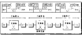
Fig. 1 is the schematic diagram according to the each several part of the multi-staged ATM node of embodiments of the invention, especially its access sub-frame and mainframe.
Fig. 2 be Fig. 1 multi-staged ATM node a part and also comprise continuing and set up the schematic diagram of manager, joint behavior monitors manager and Service Manager.
Fig. 3 is the schematic diagram of example apparatus plate of the switching port interface module (SPIM) of the ATM node that expression can resident Fig. 1.
Fig. 4 is the chart of example cell that adds the SPAS mark of the multi-staged ATM node transmission that is useful on by Fig. 1 on it.
Fig. 4 A is the chart of example cell that adds the SPAS mark of the multi-staged ATM node transmission that is useful on by Fig. 1 on it, and described example cell has AAL2 ' protocol package.
Fig. 4 B is the chart of example cell that adds the SPAS mark of the multi-staged ATM node transmission that is useful on by Fig. 1 on it, and described example cell has AAL2 " protocol package.
Fig. 4 C is the chart of example cell that adds the SPAS mark of the multi-staged ATM node transmission that is useful on by Fig. 1 on it, and described example cell is used for 8 bit Utopia equipment.
Fig. 4 D is the chart of example cell that adds the SPAS mark of the multi-staged ATM node transmission that is useful on by Fig. 1 on it, and described example cell is used for 16 bit Utopia equipment.
Fig. 5 is the schematic diagram of simplification of the multi-staged ATM node of presentation graphs 1.
Fig. 5 A is the schematic diagram of demultiplexing point in the multi-staged ATM node of describing in the presentation graphs 5.
Fig. 5 B is the schematic diagram of multiplexed point in the multi-staged ATM node of describing in the presentation graphs 5.
Fig. 5 C is the schematic diagram of transfer point in the multi-staged ATM node of describing in the presentation graphs 5.
Fig. 5 D is the schematic diagram in monitoring point in the multi-staged ATM node of describing in the presentation graphs 5.
Fig. 5 E is the schematic diagram that activates point and halt in the multi-staged ATM node of describing in the presentation graphs 5.
Fig. 6 is the making a start and the schematic diagram of terminal of section of the multi-staged ATM node of presentation graphs 1.
Fig. 7 is illustrated in the multi-staged ATM node of Fig. 1 according to the signaling of mode of the present invention in the performance monitoring example and the schematic diagram of cell flow.
Fig. 8 is the chart of expression according to the format sample of the SPAS performance monitoring cell of embodiments of the invention.
Fig. 9 is the chart that is illustrated in the transmission of the middle SPAS block of cells that continues that has the performance monitoring operation.
Figure 10 A is the routing table of describing by the optional inner route technology of multi-staged ATM cell; Figure 10 B describes according to the routing table of mode of the present invention by the inside route technology of multi-staged ATM cell.
Figure 11 is the schematic diagram with embodiment of the ring or the multi-staged ATM node of the present invention of bus topolopy.
Figure 12 is the used right chart of byte of SPAS mark that is used for the ring-type multi-staged ATM node of Figure 11.
Figure 13 A to Figure 13 F is expression through the difference of the ring-type multi-staged ATM node of Figure 11, according to the chart of SPAS mark of the present invention.
Figure 14 is that expression is the ATM cell demultiplexing with AAL2 agreement the chart with ATM cell of AAL2 master agreement.
Figure 15 is the chart for the routing iinformation byte of professional cell.
Detailed description to accompanying drawing
In the following description, unrestricted for explanation, some specific detail such as concrete structure, interface, technology etc. are proposed, so that complete understanding of the present invention is provided.But should be clear for the professional and technical personnel, the present invention can be with realizing with inconsistent other embodiment of these specific detail.In addition, omit detailed description, in order to avoid description of the invention is sunk among the unnecessary details to well-known device, circuit and method.
Fig. 1 represents the each several part according to the multi-staged ATM node 20 of embodiments of the invention.In instantiation shown in Figure 1, multi-staged ATM node 20 is arranged in frame or electric component, and frame comprises a plurality of sub-frame.For simplicity, five sub-frame 22 of multi-staged ATM node 20 only are shown among Fig. 1, are specially a main sub-frame 22
MWith four access sub-frame 22
A1To 22
A4The space exchange part of multi-staged ATM node 20 is referred to as " SPAS " hereinafter.Interface between each sub-frame 22 is called as SILI (SPAS inner link interface) 23.Cell by the SPAS transmission is called " SPAS cell " here, and (described in hereinafter) can comprise professional cell of SPAS and SPAS performance monitoring cell (being also referred to as the control cell of monitor management cell, SPAS control cell or abbreviation).
Each sub-frame is considered to have the part that comprises the ATM switch of installing above.As hereinafter illustrating in greater detail, each sub-frame 22 comprises atm switching center 24.Each switching center 24 has a plurality of switching centers port, specifically, and promptly a plurality of switching centers inlet and the outlet of a plurality of switching center.Each switching center's port is connected to switching port interface module (SPIM) 26 by link in the sub-frame.Application number on November 9th, 1998 registration is 09/188,265, is entitled as to find the example of communicating by letter between switching center and the switching port interface module in the U.S. Patent application of " asynchronous transfer mode exchange ", shows this application is incorporated herein by reference.Be connected between node the access sub-frame 22 of (for example outside) link 28
ASwitching port interface module (SPIM) be positioned on the device board 30.In order to illustrate, each sub-frame 22 of multi-staged ATM node 20 is shown in switching center 24
AEntrance side two switching port interface modules (SPIM) 26 are arranged
AWith two switching port interface modules (SPIM) 26 are arranged at outlet side
AFor example, for sub-frame 22
A1, in switching center 24
A1Entrance side, respectively in device board 30
A1-1With 30
A1-3On be provided with first cover switching port interface module or unit (SPIM) 26
A1-1With 26
A1-3In switching center 24
A1Outlet side be provided with second cover switching port interface module or unit (SPIM) 26
A1-2With 26
A1-4Switching port interface module (SPIM) 26
A1-4Be connected to sub-frame 22 (not shown) of another multi-staged ATM node 20.Switching port interface module (SPIM) 26
A1-2Being connected to main sub-frame 22M, specifically is the switching port interface module (SPIM) 26 that is connected to it
M-1In Fig. 1, for convenience, other insert sub-frame 22
ABut represent with the part that analogy is quoted.But, should be clear, these insert sub-frame needn't have same structure, but can be provided with in the above varying number switching port interface module (SPIM) 26 and can by with shown in different mode connect this switching port interface module (SPIM) 26.
As mentioned above, the switching port interface module (SPIM) 26 of serving peripheral link 28 is positioned on the device board 30 in the illustrated embodiment.Example apparatus plate 30 has been described among Fig. 3.As shown in Figure 3, device board 30 not only comprises switching port interface module (SPIM) 26, but also comprises one or more SPAS user sources 32.In the specific embodiment shown in Fig. 3, four this SPAS user sources 32 have been described.SPAS user source 32 can be for example microprocessor, digital signal processor, ATM or AAL terminal assembly, perhaps expansion end (ET).Expansion end (ET) is used in particular for (through peripheral link 28) multi-staged ATM node 20 is connected to another ATM node in the multinode network.For the function of hereinafter describing such as conversion operations and performance monitoring operation, exchange end generally has the processor (being called " sheet processor " or " BP ") that is mounted thereon.As hereinafter illustrated, according to the present invention, the sheet processor on the device board 30 at multi-staged ATM node 20 edges also plays the effect of indexing unit, refers to sheet processor/indexing unit of Fig. 3 with BP/TU for this reason.
Each SPAS user source 32 is connected to the switching port interface module (SPIM) 26 of device board 30 through SAI interface (SPAS access interface) 34.Switching port interface module (SPIM) 26 comprises hardware and software, and has the various different assemblies that comprise buffer.For example, (wherein be incorporated herein by reference) the switching port interface module (SPIM) 26 that example has been described in following U.S. Patent application all: being entitled as " having the amplification of the ATM cell of buffered data " sequence number is 08/893,507 U.S. Patent application; Being entitled as " point-to-point and/or put the buffering of multiple spot ATM cell " sequence number is 08/893,677 U.S. Patent application; With being entitled as " VP/VC locating function " sequence number is 08/893,479 U.S. Patent application.Switching port interface module (SPIM) 26 is connected to the switching center 24 of sub-frame 22 by ASCI (atm switching center interface) interface 36.
Fig. 1 mainly represents the sub-frame 22 of multi-staged ATM node 20.Except its sub-frame 22, multi-staged ATM node 20 also comprises various managers as shown in Figure 2.Continue and set up a large amount of functions of manager 50 execution, comprise that (foundation in case continue) is transmitted to indexing unit BP/TU (see figure 3) to routing label information.As described below, indexing unit BP/TU is attached to mark with designated cell by ATM node 20 routes, comprises on the professional cell that enters the ATM node.As explanation subsequently, this mark comprises, for example, is used for the tabulation by the destination address of ATM node switching cell.60 controls of joint behavior monitors manager comprise the supervision of the various interchangers (for example sub-frame) of multi-staged ATM node 20 to the cell process.In addition, professional control manager 70 is carried out various functions, comprises the function in the mark of quality of service designator insertion cell.
Continue and set up manager 50 and joint behavior monitors manager 60 and be connected to SPAS by the management of the SPAS shown in Fig. 2 (SMI) interface 38.Mistake, performance and the configuration management of treatment S PAS basically of SPAS management (SMI) interface 38.Continue and set up manager 50 and joint behavior monitors manager 60 can be located at any position easily in the multi-staged ATM node 20, be connected to switching center 24 but preferably be placed in
MOn the main processor MP on the particular device plate 30 of (see figure 1).Primary processor (MP) has the basic function of control multi-staged ATM node 20.
Although be expressed as independent piece among Fig. 2, the function of professional control manager 70 can be carried out by the various processors that are positioned within the SPAS.For example, can for example handle these functions by one or more sheet processor (BPs) with distribution form or by the main processor MP of multi-staged ATM node 20.Therefore, except local mistake and performance monitoring function, the purpose of BP can be to handle local service control.
Before the SPAS cell can enter multi-staged ATM node 20, professional control manager 70 must be set up between two SAI with specified services quality (QoS) and service parameter through SAI interface (SPAS access interface) 34 request and continue.This request of setting up that continues is received and is transmitted to continue by SPAS sets up manager 50.Continue and set up manager 50 and respond by the traversal lists that is provided for continuing to two indexing unit BP/TU.Two indexing unit BP/TU that receive traversal lists are being connected on the device board 30 that relates to these two peripheral links 28 that continue.Traversal lists be used for by the SPAS cell-switching and for the cell specified circuit by the tabulation of destination address.Being used for cell by the traversal lists of a reception among two indexing unit BP/TU specifies in by the route on 20 1 directions of multi-staged ATM node; And be used to specify route by on the rightabout of multi-staged ATM node 20 by the traversal lists of another reception among two indexing unit BP/TU.Traversal lists is written in the conversion table of two indexing unit BP/TU.
Continue set up after, when having received the ATM cell that participates in continuing from peripheral link 28, indexing unit BP/TU obtains VPI/VCI and chain line from the head of the ATM cell of input.By using these parameters, indexing unit BP/TU draws its conversion table and is that cell obtains traversal lists.In addition, professional control manager 70 also adds two parameters, is specially cell size and QoS designator.Traversal lists is called as " SPAS mark " or " routing label " here together with cell size and QoS designator, or abbreviates " mark " as.Indexing unit BP/TU is added in the SPAS mark on the whole ATM cell to form the SPAS cell, and ATM cell is a SPAS payload (see figure 4).The SPAS cell that has SPAS mark 82 is sent to SPAS through SAI interface (SPAS access interface) 34.SAI interface (SPAS access interface) the 34th is towards the interface in the user plane of SPAS.
Therefore, before entering, comprise that the SPAS mark of whole traversal lists (together with cell size and QoS mark) is added on the payload of SPAS cell by indexing unit BP/TU from SAI interface (SPAS access interface) 34.The SPAS mark is in order to propagate cell by SPAS.The terminal point that the SPAS tag definitions continues.SPAS continues and can have many continuing in proper order by it, for example continues via its multiplexed ATM.
Has format sample shown in Fig. 4 as the SPAS cell 80 that passes through the added SPAS mark 82 of indexing unit BP/TU.SPAS mark 82 is before the payload of SPAS cell 80.In the embodiment shown, SPAS mark 82 has seven bytes.First byte is called service information octet 86, and it is produced by professional control manager 70 As mentioned above.Back six bytes of SPAS mark 82 are traversal lists 88.
Service information octet 86 has following four fields: the odd field; The cell size field; The Quality of Service field; And type field.If cell is professional cell, type field (bit) is a null value; A value in the type field shows that this cell is control cell or other cells.If cell is a lowest latency priority, then qos field (dibit) is a null value, if cell is high latency priority, then qos field is a numerical value three.Cell size field (four bits) has been stored one therein and has been had from the code of zero value between nine.This code indicates the size of total cell size and cell payload.The meaning of the code of cell size is understood with reference to the table 1 of subsequent discussion.Unshowned in table 1 is cell size code 12,13,14 and 15, and they are link cells and also have the meaning same with 0,1,2 and 3 respectively.
Table 1
The cell size code that is used for service information octet
| The | 0?????1?????2?????3?????4?????5?????6?????7?????8?????9 |
| Total cell size SPAS payload size AAL2 ' payload | 12 18 24 30 36 48 60 60 60 60 5 11 17 23 29 41 53 53 ATM-ATM-cell cells, 28 14 20 26 38 45 45 x x |
As noted above, traversal lists 88 is used to the SPAS cell and specifies the tabulation that for example exchanges the destination address of SPAS cell by the route of multi-staged ATM node 20.In the illustrated embodiment, traversal lists 88 comprises six bytes.As described below, by pop operation byte shift with traversal lists 88 in traversal lists.Whole six bytes of traversal lists 88 have same form, and each all has format fields, address field and parity check bit.When the value in six bit values in address field was physical level address (six bit addresses that are address field are directly corresponding to physics output), format fields (bit) was a null value.If the value in the address field is not to be used for physical address, then format fields (bit) is a value.
When the format fields (bit) of eight bit bytes in the traversal lists 88 was zero, the value in the address field indicated at multi-staged ATM node 20 with interior physical address.In the illustrated embodiment, these addresses are the address of switching port interface module (SPIM) 26, generally are the utopia addresses therefore.
The format fields of byte in traversal lists 88 (bit) is for the moment, and the logical address in the address field (for example operation code) value has the meaning of the certain action of indication.The meaning of these logical addresses depends on whether byte is used for the classification of even number or the classification of odd number.The meaning of these logical addresses that is used for the classification (for example 2,4 and 6 grades) of even number is shown in Table 2.The meaning of these logical addresses that is used for the classification (for example 1,3 and 5 grade) of odd number is shown in Table 3.Should be noted that the byte for form one type, the logical address values in address field is only effective at the some place that handles them.
Table 2
The logical address meaning that is used for the even number classification of traversal lists
| Logical address values in the | Meaning | |
| 0 1 2 3 4 5-30 31 32-50 51-59 60-63 | Best effort is propagated and is guaranteed to propagate multicast table 1, full multicast table multicast table 2, limited multicast table multicast table 3, limited multicast table are that limited multicast continues and reserves indication " sky "; If cell reaches this degree, it should be terminated.For example, if only cross a sub-frame, then code should be inserted into the position that has neither part nor lot in route.Verified itself if reserve MP/BP to SPIM for multicast table, it then is the functional address type, if do not match, then some in the code may also can should further be broadcasted by the indicating services cell.For SPIM HW reserves, the expression cell is to be used for the inner use at the SPIM of terminal point.For example, for wrong and performance management (comprising current control). |
Table 3
The logical address meaning that is used for the odd number classification of traversal lists
| Logical address values in the | Meaning | |
| 0 1 2 3 4 5-30 31 32-63 | Best effort is propagated and is guaranteed to propagate multicast table 1, full multicast table multicast table 2, limited multicast table multicast table 3, limited multicast table are that limited multicast table is reserved indication " sky "; If cell reaches this degree, it should be terminated.For example, if only cross a sub-frame, then code should be inserted into the position that has neither part nor lot in route.Indicate the ring topological structure of purpose ring frame with addressing |
In this example, the SPAS hierarchy that has six classifications of SPAS mark 82 supports of traversal lists 88 like this.In each classification, can discern nearly 64 outputs.Indicate as mentioned, traversal lists 88 is designated as the structure that (but being not limited to) has the access sub-frame switch that is connected to host exchange.Suppose that a sub-frame (for example sub-frame 22) takies two classifications of traversal lists 88.In a pair of odd even classification in traversal lists 88 (for example first and second), first classification to the output board addressing in the sub-frame and second classification to being connected to the equipment addressing of one or two " multiphy utopia " link.
Have SPAS cell 80 explanation of form among Fig. 4 as top reference, each classification or byte in traversal lists 88 have address field, and the latter comprises or destination address, source address or address blank.Destination address in the address field of byte be used to specified circuit by after, it is replaced by the address (being source address) of the position that cell is originated.Do not use whole traversal lists 88 if continue to reach its destination, for example, only pass two sub-frame, then latter two classification is " sky ".If switching port interface module (SPIM) 26 detects source address or null value at the top of traversal lists 88, then abandon this cell.
In case enter SPAS, in traversal lists 88, be used for by the SPAS specified circuit by all address fields will be filled by effective destination address.If routing link is shorter than all possible structure, then the address field of all the other bytes in traversal lists 88 is configured to null value.If then abandon cell when null value, detects this situation at the top of traversal lists 88.Format fields (see figure 4) as each byte of top reference in traversal lists 88 is pointed, and the value in the address field can be physical address or logical address.Physical address in the address field of the byte of traversal lists 88 is accurately determined outgoing position and is used to continuing corresponding to the common point-to-point in the classification of this byte.When the format fields of the byte in the traversal lists 88 pointed out that value in the address field is logical address, this logical address was used to various other operations (see Table 2 and table 3).
In each route classification, use the destination address in the address field at top of traversal lists 88.After the destination address that utilizes about specified byte, traversal lists 88 by on push away or pop-up single order and being inserted into about the source address of pop-up byte in the address field of last byte of traversal lists 88.Like this source address of the described insertion of mark, make and can detect unlimited ring.If the top in traversal lists 88 detects source address, then abandon whole SPAS cell.Source address is represented physical resource.The last byte of the format fields bit-copy of pop-up byte in the traversal lists 88 (format fields in the last byte shows that thus the value before the address field of pop-up byte is physics or logical address).Odd is used for effective destination address, and even parity check is used for the physical resource address.If detect even parity check at the demultiplexing point, should be used as it " null value ", and whole SPAS cell be judged to invalid.
Fig. 5 is the simplification of the multi-staged ATM node 20 of Fig. 1, and main sub-frame 22 only is shown
MWith two access sub-frame 22
A1With 22
A2The reduced graph of Fig. 5 is represented the description in the concrete path of SPAS block of cells or cell flow process multi-staged ATM node 20.Mobile route is from inlet SAI interface (SPAS access interface) 34, and at this interface, the SPAS cell is drawn towards and inserts sub-frame 22
A1Switching port interface module (SPIM) 26
A1-1From switching port interface module (SPIM) 26
A1-1, cell is through center 24
A1Arrive switching port interface module (SPIM) 26
A1-2Switching port interface module (SPIM) 26
A1-2Cell is added in is used for main sub-frame 22
MSwitching port interface module (SPIM) 26
M-1The link of transmission on.From switching port interface module (SPIM) 26
M-1, cell is designated by center 24
MTo switching port interface module (SPIM) 26
M-2Route.In switching port interface module (SPIM) 26
M-2Cell is added in is used for sub-frame 22
A2Switching port interface module (SPIM) 26
A2-1The link of transmission on.From switching port interface module (SPIM) 26
A2-1, cell is designated by center 24
A2To switching port interface module (SPIM) 26
A2-2Route.From switching port interface module (SPIM) 26
A2-2Cell is added in outlet SAI interface (SPAS access interface) 34, comes out from multi-staged ATM node 20 thus.To have the physical address of following each SPIM thus with address field of the first five in six bytes of the traversal lists 88 of the cell of the designated route by multi-staged ATM node 20 of the mode of firm description: 26
A1-226
M126
M-226
A2-126
A2-2The 6th byte has the effective destination address that comes out, promptly comes out from multi-staged ATM node 20 from outlet SAI interface (SPAS access interface) 34.
Fig. 5 A represents that demultiplexing point D is at this place, promptly demultiplexing takes place in the porch of some switching port interface module (SPIM) 26 in the outlet at each center 24 and each sub-frame 22.For example after demultiplexing point D, SPAS mark 82 by pop-up or on push away single order to the point that indicates P.In a similar manner, Fig. 5 B represents to be positioned at the position of multiplexing point (" M ") of the inlet of the inlet at each center 24 and certain switching port interface module (SPIM) 26.Source address is from the physical address that pushes away the multiplexing point in front a little on the most approaching.Set up complete source address list (except the SAI address) by this way.The source address traversal lists can be used for various uses, for example, any SPAS is continued or the performance monitoring of point-to-point or any concrete segmentation.Multiplexing point is not controlled by SPAS mark 82.Therefore, the SPAS cell always is assigned to the route of the next demultiplexing point that SPAS mark 82 works.The SPAS cell that passes SAI interface (SPAS access interface) 34 must push away point (seeing Fig. 5 A and Fig. 5 B) by at least two multiplexed some M, two demultiplexing point D and one.Therefore, in the illustrated embodiment, nearly five transfer point T (for example destination address obtains the point of pop-up part) are possible (seeing Fig. 5 C).Along with destination address by pop-up, the last byte of traversal lists 88 is filled by source address as mentioned above.The source address list of setting up in traversal lists 88 can be used for the SPAS that quality participates in performance monitoring and continues thus.
The purpose of the performance monitoring of the present invention that is advanced by joint behavior monitors manager 60 is check for data block, the connecting quality of the appointment cell flow of designated route by multi-staged ATM node 20 at least a portion for example.Quality may mean for example cell loss and the error rate.In order to finish performance monitoring of the present invention, joint behavior monitors manager 60 and the various monitoring points work in concert of in SPAS, setting up.As following illustrated, may pass one or more than one section execution performance supervision of the whole route of SPAS or the route that cell passes SPAS to cell.Payload 84 to the SPAS cell 80 of the set of all cell size in defined data block and the section monitors.
Various potential monitoring point among the SPAS that Fig. 5 D represents to be utilized by joint behavior Monitoring Manager 60.Potential monitoring point comprises supervision starting point MSP; Monitor start point/end point MS/EP; With supervision terminal point MEP.Performance monitoring can be in SPAS supervision starting point MSP and any one the monitoring start point/end point MS/EP begin and supervision start point/end point MS/EP that can be in SPAS and monitor any one end among the terminal point MEP.Except these, Fig. 5 D has also illustrated four kinds of situations that how can define and monitor section by joint behavior monitors manager 60 in SPAS.First kind of information slip is shown in all possible (five) the SPIM-SPIM path that is defined as section separately in the SPAS.Second kind of situation represents that two sections being defined and monitoring, each section are the SPIM from a SPIM of sub-frame to subsequently sub-frame.The third situation is represented from SPIM26
M-1To SPIM
A2-2The section of definition.The 4th kind of situation represents to be defined as the section by the entire path of the cell of SPAS, promptly from SPAS26
A1-1To SPAS26
A2-2
Section is short more, and many more SPAS continue and can pass this section.This is to monitor after the terminal point that the demultiplexing point is arranged because before the supervision starting point multiplexed point is arranged.Largest segment span SAI (inlet) can only consider to cross continuing of these SAI to SAI (outlet).
When monitoring certain section by joint behavior monitors manager 60, supervision continues and more high-rise continuing (for example ATM continues) through all multiplexed SPAS of this section, as long as for the classification of the traversal lists 88 that comprises this section, they have the Quality of Service of appointment, at the effective physics destination address of starting point with in the effective source address of terminal point.Want effectively, physical address must comprise at least one classification.
In the supervisory work of carrying out under the control of joint behavior monitors manager 60, data block is by the initial cell that has neither part nor lot in and stop cell and limits, will control in the continuing of cell and describe the latter in more detail having SPAS subsequently.The quality of supervision all valid cells (professional cell and other) between initial cell and termination cell.
Foundation by the supervisory work of joint behavior monitors manager 60 management has three phases-activation stage; The supervision stage; And the report stage.Before each stage is discussed, mentions about the activation point of performance monitoring earlier and stop using a little.Fig. 5 E is illustrated in activation point potential in the continuing of embodiment previously discussed particularly and stops using a little.Fig. 5 E represents the position of following potential point: activate point (AP); Activation/reporting point (A/RP); And reporting point (RP).From Fig. 5 E as can be seen, SPIM26
A1-1Only can be used as and activate point (AP); SPIM26
A2-2Only can be used as reporting point (RP); And SPIM26
A1-2With 26
M-2Can be used as or activate a little or reporting point, for example can be used as activation/reporting point (A/RP).Activate point and be under 60 management of joint behavior monitors manager and can startability to monitor and the point of definition phase size.Activate point and only can be defined in the section that begins among the same SPIM.Similar, reporting point only can be operated the supervision terminal point in same SPIM.
Understand the function that activates point and reporting point with reference to Fig. 6.Fig. 6 represent particularly to be positioned at monitored the section end points on two SPIM26.In Fig. 6, claim SPIM26
OBe the SPIM that makes a start, and claim SPIM
TBe terminal SPIM.The section that is monitored can be a section among any SPAS, for example, and shown in Fig. 5 D any section.Each SPIM26
OWith 26
TBe represented as having sheet processor (BP) and hardware (HW).SPIM26
OBe represented as having activation point AP in its sheet processor (BP) and the supervision starting point (MSP) in its hardware.Similarly, SPIM26
THave reporting point RP in its sheet processor (BP) and the supervision terminal point (MEP) in its hardware.SPIM26
OWith 26
TBe expressed as being positioned on their sub-frame 22 separately, each sub-frame 22 has switching center (ASCM) 24.
Because traversal lists 88 is set up as a pair of destination address, pilot signal must pass two ASCM (switching center) in the sub-frame, sees Fig. 6 so that cross over SILI interface (SPAS inner link interface) 23[].Under the management of joint behavior Monitoring Manager 60, SPIM26
OAnd SPIM26
TIn sheet processor BP carry out monitoring.As shown in Figure 6, all control signals in stage 1 (activation stage) and stage 3 (report stage) are directly at SPIM26
OAnd SPIM26
TSheet processor between transmit.In the stage 2 (supervision stage), by monitor starting point MSP and monitor terminal point MEP discern beginning and termination signal (conduct subsequently " beginning " and " termination " SPAS controls cell and described in more detail).Continuing of being monitored only is monitored an identification during monitoring.
SPIM26 makes a start
OWith terminal SPIM26
TThe sheet processor utilization be called SPAS performance monitoring cell, be also referred to as " the monitor management cell ", " SPAS controls cell " or abbreviate as " the control cell " and special cell intercom mutually.The format sample of the performance monitoring of SPAS shown in Fig. 8 cell.In the embodiment shown, each SPAS performance monitoring cell length is three crosses joints.In such an embodiment, SPAS performance monitoring cell has five field: header field 8-1; Performance monitoring code field 8-2; Relevant field 8-3; Data field 8-4; With Cyclic Redundancy Check field 8-5.All field length except header field 8-1 and data field 8-4 only are a byte, and header field 8-1 is that seven bytes and data field 8-4 are two crosses joints.The header field 8-1 of SPAS performance monitoring cell is the mark that applies for the tagged indexing unit of professional cell (BP/TU) by also.
Can monitor as indicated in the value among the code field 8-2 that as do as one likes SPAS performance monitoring cell can be one of three types.If the performance monitoring code has null value, then SPAS performance monitoring cell shows that performance monitoring is activated.Activate SPAS performance monitoring cell and have comparing data at its data field 8-4, the latter can be monitored which QoS parameter (QoS) of partly coming under observation and being used to monitor that terminal point uses and points out traversal lists 88.By " comparing data " mean by terminal SPIM26
TBe used to be provided with the content of the whole traversal lists of its surveillance operation.
If the performance monitoring code value is one, then SPAS performance monitoring cell is from terminal SPIM26
TSend and show terminal SPIM26
TWhether accept function for monitoring " response " cell.If the performance monitoring code value is one, then SPAS performance monitoring cell is from terminal SPIM26
TIssue the SPIM26 that makes a start
O" result " cell and in its data field 8-4, have from the data that are monitored that monitor that terminal point MEP collects.
Fig. 7 furnishes an explanation all three phases-activation stage; The supervision stage; The performance monitoring example of report stage.As incident 7-1, joint behavior monitors manager 60 is to the SPIM26 that makes a start
OSheet processor send the startability supervisory signal.Incident 7-1 begins the activation stage.
As the part in the stage of activation, SPIM26 makes a start
OSheet processor (BP) to terminal SPIM26
TSheet processor (BP) send and activate SPAS performance monitoring cell as incident 7-2.It is zero performance monitoring code (see figure 8) that activation SPAS performance monitoring cell has in its field 8-2, and in its data field 8-4, have whole traversal lists, and the Quality of Service parameter that relates to supervision with the comparing data that acts on supervision.Simultaneously, the SPIM26 that makes a start
OMonitoring that starting point (MSP) preparation is used for the hardware resource of supervision stage (as indicated in incident 7-3).The preparation of incident 7-3 means, monitor starting point (MSP) beginning (1) seek start respectively and stops to the supervision of the section that is monitored begin control cell and stop the control cell, and (2) [control cell and stop between the control cell beginning] sought the cell of the qos parameter of the specific traversal lists form that is designated as comparing data in its traversal lists 88 when having in activation simultaneously and appointment.
In case receive the activation SPAS performance monitoring cell that sends as incident 7-2, terminal SPIM26
TSheet processor (BP) analyze to activate the content (the data field 8-4[that especially comprises whole traversal lists and quality of service designator sees Fig. 8]) of SPAS performance monitoring cell and definite terminal SPIM26
TWhether can participate in by the SPIM26 that makes a start
OThe performance monitoring of request.The reason that can not participate in performance monitoring may be, at target terminal SPIM26
TIn be deficient in resources, perhaps shared by the performance monitoring of other activation or other activities in the existing resource of switching port interface module (SPIM) 26.If terminal SPIM26T determines that it can participate in performance monitoring, then switching port interface module (SPIM) 26 is prepared its resource for this supervision, shown in incident 7-3.The preparation of incident 7-3 relates to terminal SPIM26
TSheet processor (BP), it is to terminal SPIM26
THardware (HW) suggestion: terminal SPIM26
TSupervision terminal point (MEP) should in the selected portion of traversal lists 88, seek SPAS mark 82 for participating in cell with certain source address and QoS, and in traversal lists 88, search the particular code that indicates beginning and stop supervision.Terminal SPIM26
TAlso to the SPIM26 that makes a start
OSend response SPAS performance monitoring cell as incident 7-4, expression terminal SPIM26
TWhether can participate in performance monitoring.As noted earlier, response SPAS performance monitoring cell is a (see figure 8) in its performance monitoring code field 8-2 intermediate value.
In case from terminal SPIM26
TReceive response SPAS performance monitoring cell, the supervision stage begins (see figure 7).Generally in the supervision stage, monitor starting point (MSP) in traversal lists 88, have until the supervision terminal point of appointment, for example arrive terminal SPIM26
TThe SPAS block of cells of common physical destination address produce checking data.In the supervision stage, at the SPIM26 that makes a start
OSupervision starting point (MSP) and at terminal SPIM26
TSupervision terminal point (MEP) all to check SPAS mark, particularly its traversal lists 82 in the SPAS cell of reception, to find their specific format.Monitoring form that starting point (MSP) finds and monitoring that the form that terminal point (MEP) finds is different, in the suitable byte of traversal lists 88, seeks concrete destination address because monitor starting point (MSP), and supervision terminal point (MEP) is searched and is identified the SPIM26 that makes a start
OSource address.
Describe in more detail the supervision stage now, under the management of joint behavior Monitoring Manager 60, SPIM26 makes a start
OSend SPAS control cell, the latter comprises the beginning code of two joints, i.e. " 62 " value (seeing Table 2) in the address field of two bytes in the traversal lists 88 of SPAS mark 82.The beginning code is included in and depends in which two byte and corresponding to the position that monitors terminal point.In other words, in traversal lists, the beginning code is replaced by corresponding to two positions (for example two classifications) of supposing the SPIM that the beginning code is worked.When monitoring that starting point (MSP) detects when containing the SPAS control cell that begin code, supervision is at the SPIM26 that makes a start
OBeginning.And if having found to monitor from the beginning code to begin, supervision starting point (MSP) is then deleted the first segment of beginning code and is therefore replaced with the address that monitors starting point from traversal lists.In view of this replacement, SPIM checks a correlation, and the latter is stored between active period by this floor treater (see figure 6) of the SPIM that correlation is relevant therewith, is the real marking value for position in SPIM.By this way, SPAS cell (it also comprises second joint of beginning code) is continued in the address that monitors starting point (MSP).
Fig. 7 represents as same SPAS control cell incident 7-5, that have the beginning code from the SPIM26 that makes a start
OTo terminal SPIM26
TTransmission.When the same SPAS that detects second joint that comprises the beginning code at supervision terminal point (MEP) controls cell, monitor at terminal SPIM26
TBeginning.Cause terminal SPIM to realize that it is for monitoring terminal point in appearance corresponding to (second joint) beginning code of certain position of the traversal lists that monitors terminal point (MEP).With as in the similar fashion that monitors that starting point (MSP) is done, terminal SPIM replaces this joint to begin code with the address of terminal SPIM, makes the SPAS cell can continue a complete traversal lists.
From the SPIM26 that makes a start
OTo terminal SPIM26
TOther SPAS cell flows (they may be professional cells and may comprise other SPAS control cell) represent (see figure 9) by incident 7-6.The SPAS cell can be the size (seeing the description to cell size field in the service information octet 86 of Fig. 4) of any permission.In its traversal lists 88, has the SPAS cell of comparing data form for each, at the SPIM26 that makes a start
OWith terminal SPIM26
TIn all produce monitoring data.
As the part of the incident 7-6 of supervisory work, when the SPAS cell from the SPIM26 that makes a start
OTransfer to terminal SPIM26
TThe time (seeing Fig. 7 and Fig. 9), at the SPIM26 that makes a start
OWith terminal SPIM26
TIn all keep monitoring data.Monitoring data can be several traditional forms, but preferably by means of to the integrity checking of all this cells and cell count and/or the integrity checking of payload 84 contents.
Under the supervision of joint behavior monitors manager 60, in the suitable moment, the SPIM26O that makes a start sends SPAS control cell, and the latter comprises termination code, i.e. " 63 " value in the address field of two bytes of the traversal lists 88 of SPAS mark 82.The same with the beginning code of two joints, the termination code of two joints takes place in the classification corresponding to the traversal lists that monitors starting point (MSP) and supervision terminal point (MEP).When monitoring that starting point (MSP) detects the SPAS control cell that has termination code, SPIM26 makes a start
OStop to collect monitoring data, and replace the first segment of termination code with the address that monitors starting point (MSP).The SPAS control cell that also has termination code second joint is sent to terminal SPIM26
TOn, indicate as the incident among Fig. 77.When monitoring that terminal point (MEP) is received the SPAS control cell of second joint that has termination code, terminal SPIM26
TAlso stopping it replaces second of termination code to save to the collection of monitoring data and with the address that monitors terminal point (MEP).In fact, at the SPIM26 that makes a start
OTerminal SPIM26
TThe performance monitoring data of collecting are freezed.SPIM26 makes a start
OSheet processor (BP) and terminal SPIM26
TSheet processor (BP) all produce the monitoring data result, as respectively by shown in incident 7-8 and the incident 7-9.In the process that produces the monitoring data result, the sheet processor of SPIM (BP) reads the register of wherein storing monitoring data.
Generate the monitoring data result in case finish, as incident 7-10, terminal SPIM26
TSheet processor (BP) to the SPIM26 that makes a start
OSheet processor (BP) send result report, also be referred to as the terminal unit report.Result's report is included in the aforesaid report SPAS performance monitoring cell.Specifically, the data field 8-4 of SPAS performance monitoring cell is included in the monitoring data result who monitors that terminal point (MEP) is collected.
In case from terminal SPIM26
TReceive report SPAS performance monitoring cell, SPIM26 makes a start
OSheet processor (BP) execution analysis with relatively from terminal SPIM26
TThe result of the result who receives and its oneself is shown in incident 7-11.SPIM26 makes a start
ODraft conclusion according to its analysis, and the conclusion report is sent to joint behavior monitors manager 60, shown in incident 7-12.As noted, joint behavior monitors manager 60 may be arranged in the primary processor of multi-staged ATM node.
As the alternative scheme to above-mentioned report scheme, SPIM26 makes a start
OWith terminal SPIM26
TCan transmit its performance monitoring data result to joint behavior monitors manager 60 respectively, but so that joint behavior monitors manager 60 execution analyses.
Now forward table 1 to, each cell size code of service information octet 86 is specified a packet size, comprises total cell size, SPAS payload size and AAL2 ' payload size.AAL2 ' (also being written as the AAL2 apostrophe) is special agreement, on November 9th, 1998 registration, sequence number is 09/188,102, is entitled as " the asynchronous mode transfer system " U.S. Patent application in it has been described, now be incorporated herein by reference.The AAL2 bag that AAL2 apostrophe (AAL2 ') requires to carry in the ATM cell payload is complete bag, and the ATM payload does not have the beginning field of AAL2 type.Preferably, in AAL2 apostrophe agreement, each ATM cell payload only carries a complete AAL2 bag.Should remember that AAL2 is the standard by ITU standard I .363.2 definition.AAL2 comprises the bag head of three bytes, wraps payload in addition.AAL2 bag head comprises the Channel Identifier (CID) of eight bits, the length indicator of six bits (LI), and the user of five bits is to the head mistake control (HEC) of user's designator (UUI) and five bits.Carry the AAL2 bag payload of user data, can from one to 45 byte change.Figure 14 is the chart that expression becomes to have the ATM cell of AAL2 apostrophe agreement to the ATM cell demultiplexing with AAL2 agreement.
Reflect that as table 1 the cell size code 1-6 in service information octet 86 is (if be ready, perhaps being used for another kind of ATM form) that is used for AAL2 ' form.Fig. 4 A has represented to carry the form of the SPAS cell 80A of ALL2 ' bag.As the every other cell that sends through multi-staged ATM node 20, the SPAS cell 80A of Fig. 4 A has SPAS mark 82.SPAS mark 82 has and seven identical shown in Fig. 4 byte formats.AAL2 ' bag 400A follows after SPAS mark 82, and it comprises AAL2 ' head 402A and AAL2 ' bag payload 404A.AAL2 ' bag payload 404A portability is 45 bytes nearly.Need then must be divided into two AAL2 ' bags to the AAL2 bag more than 45 bytes if be multiplexed into the AAL2 bag of AAL2 ' agreement.First bag uses the size of LI sign indicating number (seeing Fig. 4 A) to show that fixing predefine AAL2 ' wraps greater than 45 (for example, 48), for example, and 32 bytes.Back one actual size in bright two bags of LI code table of the AAL2 ' bag in back.In case receive two AAL2 ' bags at receiver side, just it be assembled into a unit.AAL2 ' head is protected by odd parity bit.
Cell size code 7 (seeing Fig. 4 and table 1) in service information octet 86 is used for another agreement AAL2 " (also writing AAL2 two left-falling strokes).AAL2 is called in Fig. 4 B explanation " the SPAS cell 82B of agreement, also explanation has AAL2 " AAL2 of agreement " bag 400B.At AAL2 " in the agreement, in ATM cell, carried AAL2 ' bag (such as AAL2 ' bag 400A), and indicate with ATM-VCI and to continue.SPAS cell 80B is followed by AAL2 from SPAS mark 82 (with the same form of Fig. 4) " bag 400B.AAL2 " bag 400B comprises ATM head (5 bytes comprise the ATM-VCI that 12 bits activate) and AAL2 ' bag 400A.At AAL2 " in the agreement, AAL2 ' VCI is copied in 12 least significant bits of ATM VCI at least.Highest significant position such as VPI, PTI and CLP are set to zero.
AAL2 " agreement allows to finish AAL2 ' and AAL2 in the hardware of switching port interface module (SPIM) 26 " between be easy to protocol conversion.This conversion externally equipment/assembly is only discerned and is had the ATM head but not can be useful under those situations of six crosses of AAL2 ' joint cell.The example of those situations is and AAL5-SAR (Segmentation and Reassembly) assembly of primary processor (MP) interface or exchange termination (ET) [under latter event, if for certain reason AAL2 " replace AAL2 with on the atm link externally].
For cell size code 7-9, must make additional coupling for the Utopia realization of reality, this depends on whether Utopia equipment is eight bits or 16 bit widths.Fig. 4 C represents to be used for the example atm cell format of 8 bit Utopia, and it comprises that SPAS mark 82 and total SPAS cell size are 60 bytes.Multi-staged ATM node 20 shifts whole ATM cell pellucidly between two end points.On the other hand, Fig. 4 D represents to be used for the example atm cell format of 16 bit Utopia, and it comprises that SPAS mark 82 and total SPAS cell size are 62 bytes.For Fig. 4 D cell, multi-staged ATM node 20 has been eliminated byte 8 and byte 14 during internal transmission.Byte 9-13 and 15-62 are transported (because multi-staged ATM node 20 will be changed where necessary) pellucidly between two kinds of Utopia forms.
Cell size code 8 (seeing Fig. 4 and table 1) is used to represent transparent ATM cell.Cell size code 9 is used to express possibility and is subjected to the ATM AAL5 cell of early stage grouping deletion (EPD).Cell size code 12-15 is that use the inside that is used for multi-staged ATM node 20, and cell size code 10 is given over to use in the future.
Multi-staged ATM node 20 also can be constructed with bus or ring structure, for example, and as shown in figure 11.The ring-type multi-staged ATM node 20R of Figure 11 comprises n sub-frame, specifically, comprises sub-frame 22
R0To 22
Rn Sub-frame 22
RConnect by bus or ring R.In embodiment in front, each sub-frame 22
RHas the switching center 24 that is connected between two groups of switching port interface modules (SPIM) 26.For example, sub-frame 22 has switching center 24
R0Switching port interface module (SPIM) 26
R0-1(also being designated as " SPIM# 2 "); Switching port interface module (SPIM) 26 with (adr) 0 in the address
R0-2(also being designated as " SPIM# 0 ").At address adr=1, SPIM 26
R2Be connected to ring R.Switching port interface module (SPIM) 26
R0-1(in the mode of similar Fig. 1) is expressed as being positioned at device board 30
R0-1On.For simplicity, in discussion subsequently, will be reduced to sub-frame 22 to the label of various switching port interface modules (SPIM) 26
R0-1On SPIM# 0 and SPIM# 2, sub-frame 22
R1-2On SPIM26
R1-2And sub-frame 22
R2On SPIM# 5 and SPIM#28, as shown in figure 11.
When bus or ring structure were used for multi-staged ATM node, SPAS mark 82 represented two adjacent byte combinations the byte of bus or ring right to produce.It is right to express this byte with byte to 1200 in Figure 12.Be provided with following field in to 1200 first byte in byte: format fields 1202; Type field 1204; (bus or ring) destination address field (DAF) 1206; With odd field 1208.Type field 1204, when being made as zero, bus or ring structure have been quoted in expression.In the illustrated embodiment, bus or ring structure can be supported nearly 32 sub-frame.Destination address field (DAF) 1206 comprises the address of target ring frame.Provide following field in to 1200 second byte in byte: " L " field 1210; " SEQ " field 1212; (bus or ring) source address field 1214; And even parity check field 1216.For " L " field 1210, " 1 " presentation logic address (in this case, logical address taken provide comprise broadcasting, multicast and resource displacement, destination address and source address 2
10The destination of individual logical combination)." SEQ " field 1212 can be as the sequence counter on the link group or if necessary, is used to expand logical address field.
Under the sample situation of the multi-staged ATM node 20R that uses ring, the sub-frame that generally enters the mouth is connected to encircle upward and export sub-frame and is connected on the ring.Represented this sample situation among Figure 11, wherein sub-frame 22
R0The sub-frame 22 as the inlet sub-frame
R2With sub-frame for export, two sub-frame 22
R0With 22
R2All be connected on the ring R.Each sub-frame is connected to ring R through SILI interface (SPAS inner link interface) 23R.The closed hoop that SILI23R is linked to be from the sub-frame to the sub-frame connects.The physical circuit of ring R is two-way in the illustrated embodiment, still should be understood that also and can use unidirectional line.
At Figure 11 in the illustrated and sample situation that also be described with reference to figure 13A-Figure 13 F, the SPAS cell from sub-frame 22
R0On SPIM#2 (be SPIM 26
R0-1) send to address adr=4 (this address and sub-frame 22
R2On SPIM# 5 link to each other).Figure 11 represents six specified points of moving process, is specially an A-F for this SPAS cell.Express the SPAS mark 82 that is used for transfer point A among Figure 13 A; Express SPAS mark 82 that is used for transfer point B or the like among Figure 13 B.Therefore, subsequently will be the mobile detailed description of F (this equipment has adr=4) to putting to cell with reference to figure 13A-Figure 13 F from an A (SPIM# 2).Because push away the byte of SPAS mark 82 in a looping fashion, so the first classification byte is designated as byte O1, the second classification byte is designated as O2 or the like.
Some A in Figure 11, SPAS mark 82 is as shown in Figure 13 A.Thereby SPAS mark 82 has centre two bytes (O3 and O4) of above-mentioned byte to the traversal lists of 1200 forms (seeing Figure 12).After cell leaves an A, center 24
R0Specify the sub-frame 22 that arrives at address adr=0 for cell
R0The route of SPIM#0.In the process of doing like this, center 24
R0In the highest byte (byte O1) of traversal lists 88, replace destination address with source address (address of SPIM#2).
When cell arrived the inlet of SPIM# 0, SPIM# 0 changed the parity check of the highest byte (byte O1) of traversal lists 88, changes even parity check into from odd, then the bottom of highest byte (byte O1) from the top pop-up of traversal lists 88 to traversal lists 88.Therefore, in a B (in the inside of SPIM#0), SPAS mark 82 is as shown in Figure 13 B.SPIM# 0 then checks the highest byte (byte O2) of traversal lists 88, and determines that thus next physics destination address is adr=1.Physics destination address adr=1 is the address of ring R.Although undeclared, should consider, can be connected to SPIM#0 (or any other SPIM, about that) to several other rings.SPIM# 0 replaces destination address with its address in the highest byte (byte O2) of traversal lists 88, change parity check, the highest byte of traversal lists 88 (byte O2) pop-up, make byte O2 forward the bottom of traversal lists 88 to, as shown in Figure 13 C then.
The cell that has SPAS mark 82 as shown in Figure 13 C moves on ring R up to it and is accepted by the sub-frame of the destination address field (DAF) sign at the top of traversal lists 88.The mobile some C that is expressed as among Figure 11 on ring R.In sub-frame 22
R1In, through its center 24
R1Transmit cell pellucidly, because indicate center 24 at the form and the type code of byte in to 1200
R1Do not contact this cell.
When arriving it, cell (is sub-frame 22 in ring address 2
R2) the ring destination address of SPIM#28 the time, accept this cell by SPIM#28.And, SPIM#28 in the byte at traversal lists 88 tops to 1200, for example the parity check of byte O3 and O4 is from very changing into idol, and byte is shifted onto the bottom to 1200 from the top of traversal lists 88.Thereby, entering center 24 as cell from SPIM#28
R2Some D, SPAS mark 82 is shown in Figure 13 D.
Thereby preamble has been described the route of cell through multi-staged ATM node 20 with ring topology structure, and byte has been described to 1200 use, and the pop-up (this is common to all topological structures) of byte in traversal lists 88.Thereby SPAS mark 82 of the present invention is applicable to the multi-staged ATM node 20 with ring or bus topolopy.
Table 4
The explanation of the destination field in the traversal lists of professional cell
| The destination | Meaning | |
| 0 1 2 3 4 5-30 31 32-63 | At unappropriated crosspoint broadcast, all crosspoints that load, with former state independent multicast table 1, whole multicast table multicast tables 2, limited multicast table multicast table 3, limited multicast table are that limited multicast continues to reserve and points out " sky "; If cell should be terminated to the ring topological structure and reserve (center is that cell is assigned to specified address in the predetermined register or to the route in source, the routing iinformation byte does not change) so far |
Though this specification has utilized the example of the multi-staged ATM node 20 of the traversal lists 88 with level that six SPAS cell nearly can pass and consequent six bytes,, should be understood that principle of the present invention is not limited to this concrete example.In addition, more or less level can appear in the multi-staged ATM node 20, thereby the length of traversal lists 88 is also variable.
Similarly, what other parameters described herein neither be crucial, but can set other values in other embodiments.For example, the size of SPAS performance monitoring cell is only to be used to illustrate but variable parameter as three crosses joint.Under kindred circumstances, if SILI interface 23 and SAI interface appear among the same SPIM, the address field of the byte of traversal lists 88 can be separated.
In the explanation that provides with for example Fig. 5 and Fig. 5 A-Fig. 5 D, described cell from right to left and moved.But the reader should be understood that cell also moves from left to right, and this cell also by according to principle specified circuit of the present invention by and monitor.
The reader will be further appreciated that needs the time so that make the performance monitoring process firm in various SPIM, for example, the signal that responds for needs is provided with local timer.The regulation of timer and use are just in time in professional and technical personnel's ken.
The invention provides the favorable method of the performance monitoring that is used for multi-staged ATM node.Can monitor any by the continuing of node or its each section, so that test example such as early stage performance degradation.
The present invention is scalable and upgradeable.And, if performance monitoring function described herein be ready, can partly introduce step by step.For example, if think once only to handle the section beginning or end of an activation, used hardware can be designed to cheaply.Subsequent software can be used for handling simultaneously a plurality of sections.
It is many-sided that the present invention adopts the advantage of routing label (for example the SPAS mark 82).Specifically, in order to specify a plurality of grades route to ATM cell, after additional routing label, do not carry out the VPI/VCI conversion by multi-staged ATM node 20.The quantity of internal control passage has also reduced, and shortened the settling time of continuing.These all give the credit to the following fact: multi-staged ATM node 20 with interior inner link in, the mapping between the VPI/VCI is unwanted.The advantage of inner route of the present invention shown in Figure 10 B, for example can be come to understand with reference to the replacement technology shown in Figure 10 A.In Figure 10 A, for simplicity, expansion end (ET) is expressed as being connected to switching center 24, rather than is connected to the entire equipment plate 30 that has switching port interface module (SPIM) 26.Figure 10 A represents the replacement technology, wherein three sub-frame, specifically is that sub-frame A, sub-frame B and sub-frame C carry out the VPI/VCI conversion between any two.
Can in other ways of realization, utilize routing label of the present invention, and if can be with it with marking and do not detect coupling, it is delivered to next node in chain or the ring.In this case, may expand the mark that is transmitted with node address.In this case, expansion end (ET) must be set up in advance, will where not transmit to cell so that know if detect coupling.
Got in touch and be considered to the most practical and illustrated embodiments at present and described the present invention, understand, the present invention is not limited to disclosed embodiment, and opposite, it is intended to contain various modifications and equivalent within the spirit and scope that are included in the claims of enclosing.
Claims (56)
1. ATM node, it comprises:
A plurality of ATM switch that link together;
Continue and set up manager, it is attached to mark on the cell of designated route by the ATM node, and described mark comprises and is used to specify the tabulation of cell by the destination address of the route of described ATM node;
The joint behavior monitors manager, the section of described a plurality of ATM switch of the described ATM node of cell process that its definition is monitored, and on defined section, activate the performance monitoring that utilizes mark.
2. the device of claim 1, it is characterized in that: described joint behavior monitors manager activates from described section make a start to the performance monitoring of described section terminal, and described node also is included in the terminal monitors unit of described section terminal, the latter determines with the described mark of the cell that receives whether the cell that receives is subjected to performance monitoring, and prepares the terminal unit report about the cell that is subjected to performance monitoring.
3. the device of claim 1, it is characterized in that: each in described a plurality of ATM switch has the switching center between two switching port interface modules.
4. the device of claim 3 is characterized in that: one of described switching port interface module that described section make a start is arranged in described node goes up and described section terminal is positioned on another of described switching port interface module of described node.
5. the device of claim 1, it is characterized in that: described ATM node also comprises the professional control manager of the quality of service designator being inserted the described mark of described cell.
6. the device of claim 1 is characterized in that: described mark comprises the tabulation of six destination addresses that are used to exchange the described cell by described ATM node.
7. the device of claim 1 is characterized in that: described joint behavior monitors manager is inserted in the mark of control cell code, will begin or monitor termination to the one or more destination address execution monitoring of listing in the mark so that indicate whether.
8. the device of claim 7, it is characterized in that: in a plurality of destination addresses in the described mark each, described mark comprises optionally the code that inserted by the joint behavior monitors manager monitors whether begin or from the section by relevant destination address restriction with indication.
9. the device of claim 1 is characterized in that: described joint behavior monitors manager make the monitor management cell described section make a start and described section terminal between transmit.
10. the device of claim 9 is characterized in that: at least one is to send, monitor that with the notice terminal capabilities supervision that has been activated activates cell from described section make a start in the described monitor management cell.
11. the device of claim 9 is characterized in that: described supervision activates cell and specifies the destination address that relates to described performance monitoring.
12. the device of claim 11 is characterized in that: described supervision activates cell and also specifies the certain quality of service that relates to described performance monitoring.
13. the device of claim 9 is characterized in that: at least one in the described monitor management cell is the response cell, and it sends to confirm that to making a start described terminal has been that performance monitoring is got ready from described section terminal.
14. the device of claim 9 is characterized in that: at least one in the described monitor management cell is to monitor cell as a result, and it is issued from described section described terminal and describedly makes a start and comprise monitoring data.
15. the device of claim 14 is characterized in that: described monitoring data be cell count and integrity checking and one of.
16. an ATM node comprises:
A plurality of ATM switch that link together;
Continue and set up manager, it is attached to mark on the cell of designated route by the ATM node, and described mark comprises and is used to specify the tabulation of cell by the destination address of the route of described ATM node;
The joint behavior monitors manager, the cell that its definition is monitored is through the section of described a plurality of ATM switch of described ATM node, and, on described one or more section, optionally begin and stop utilizing the performance monitoring of mark by in the mark of selected cell, comprising the code that indicates whether about described one or more section beginning or stop monitoring.
17. the device of claim 16, it is characterized in that also being included in the terminal monitors unit of described section terminal, the described mark of the cell that The latter receives determines whether the cell of described reception is subjected to performance monitoring, and prepares the terminal unit report about the cell that is subjected to performance monitoring.
18. the device of claim 16 is characterized in that: each in described a plurality of ATM switch has the switching center between two switching port interface modules, link connect described switching center with one of described switching port interface module of one-level.
19. the device of claim 18 is characterized in that: one of described switching port interface module that described section make a start is arranged in described node goes up and described section terminal is positioned on another of described switching port interface module of described node.
20. the device of claim 16 is characterized in that: described ATM node also comprises the professional control manager of the quality of service designator being inserted the described mark of described cell.
21. the device of claim 16 is characterized in that: described mark comprises the tabulation of six destination addresses that are used to exchange the described cell by described ATM node.
22. the device of claim 16 is characterized in that: described joint behavior monitors manager make the monitor management cell described section make a start and described section terminal between transmit.
23. the device of claim 22 is characterized in that: at least one is to send so that the supervision of notifying described terminal capabilities supervision to be activated activates cell from described section make a start in the described monitor management cell.
24. the device of claim 22 is characterized in that: described supervision activates cell and specifies certain destination address that relates to described performance monitoring.
25. the device of claim 24 is characterized in that: described supervision activates cell and also specifies the certain quality of service that relates to described performance monitoring.
26. the device of claim 22 is characterized in that: at least one in the described monitor management cell is the response cell, and it sends to confirm that to described making a start described terminal has been that performance monitoring is got ready from described section terminal.
27. the device of claim 22 is characterized in that: at least one in the described monitor management cell is to monitor cell as a result, and it is issued from described section described terminal and describedly makes a start and comprise monitoring data.
28. the device of claim 27 is characterized in that: described monitoring data be cell count and integrity checking and one of.
29. an operation comprises the method for the ATM node of a plurality of ATM switch that link together, described method comprises:
Mark is attached on the cell of designated route by described ATM node, described mark comprises and is used to specify the tabulation of cell by the destination address of the route of described ATM node;
The cell that definition is monitored is through the section of described a plurality of ATM switch of described ATM node;
On defined section, activate performance monitoring; With
Determine with the described mark of the cell that receives whether the cell that receives is subjected to performance monitoring.
30. the method for claim 29 is characterized in that also comprising the report of preparation about the cell that is subjected to performance monitoring.
31. the method for claim 29 is characterized in that: each in described a plurality of ATM switch has the switching center between two switching port interface modules.
32. the method for claim 31 is characterized in that: one of described switching port interface module that described section make a start is arranged in described node goes up and described section terminal is positioned on another of described switching port interface module of described node.
33. the method for claim 29 is characterized in that also comprising the described mark that the quality of service designator is inserted described cell.
34. the method for claim 29 is characterized in that: described mark comprises the tabulation of six destination addresses that are used to exchange the described cell by described ATM node.
35. the method for claim 29 is characterized in that also being included in and inserts the code that indicates whether to begin the one or more destination address execution monitoring of listing or to monitor end in described mark in the described mark.
36. the method for claim 35 is characterized in that: in a plurality of destination addresses each, optionally in the mark of control cell, insert code so that indication whether monitor will from the section startup that limits by relevant destination address or.
37. the method for claim 29, it is characterized in that also being included in described section make a start and described section terminal between the transmitting monitoring management cell.
38. the method for claim 37 is characterized in that also comprising that the transmitting monitoring of making a start from described section activates cell, is activated to notify described terminal capabilities to monitor.
39. the method for claim 37 is characterized in that also being included in described supervision and activates in the cell and comprise certain destination address that relates to described performance monitoring.
40. the method for claim 39 is characterized in that also being included in described supervision and activates in the cell and comprise the certain quality of service that relates to described performance monitoring.
41. the method for claim 37 is characterized in that also comprising from described section terminal sending the response cell to confirm that to described making a start described terminal has been that performance monitoring is got ready.
42. the method for claim 37 is characterized in that also comprising that from described section terminal to the described transmitting monitoring cell as a result of making a start, described supervision cell as a result comprises monitoring data.
43. the method for claim 42 is characterized in that: described monitoring data be cell count and integrity checking and one of.
44. an operation comprises the method for the ATM node of a plurality of ATM switch that link together, described method comprises:
Mark is attached on the cell of wanting designated route by described ATM node, and described mark comprises and is used to specify the tabulation of cell by the destination address of the route of described ATM node;
The cell that monitored of definition is through one or more section of described a plurality of ATM switch of described ATM node;
In described mark, comprise indication about the defined section code that whether will begin or stop supervision; With
Determine with the described mark of the cell that receives whether the cell that receives is subjected to performance monitoring.
45. the method for claim 44 is characterized in that also comprising the report of preparation about the cell that is subjected to performance monitoring.
46. the method for claim 44 is characterized in that: each in described a plurality of ATM switch has the switching center between two switching port interface modules.
47. the method for claim 46 is characterized in that: one of described switching port interface module that described section make a start is arranged in described node goes up and described section terminal is positioned on another of described switching port interface module of described node.
48. the method for claim 44 is characterized in that also comprising the quality of service designator is inserted in the described mark of described cell.
49. the method for claim 44 is characterized in that: described mark comprises the tabulation of six destination addresses that are used to exchange the described cell by described ATM node.
50. the method for claim 44, it is characterized in that also being included in described section make a start and described section terminal between the transmitting monitoring management cell.
51. the method for claim 50 is characterized in that also comprising that the transmitting monitoring of making a start from described section activates cell, is activated to notify described terminal capabilities to monitor.
52. the method for claim 50 is characterized in that also being included in described supervision and activates in the cell and comprise certain destination address that relates to described performance monitoring.
53. the method for claim 50 is characterized in that also being included in described supervision and activates in the cell and comprise the certain quality of service that relates to described performance monitoring.
54. the method for claim 50 is characterized in that also comprising from described section terminal sending the response cell to confirm that to described making a start described terminal has been that performance monitoring is got ready.
55. the method for claim 50 is characterized in that also comprising that from described section terminal to the described transmitting monitoring cell as a result of making a start, described supervision cell as a result comprises monitoring data.
56. the method for claim 55 is characterized in that: described monitoring data be cell count and integrity checking and one of.
Applications Claiming Priority (2)
| Application Number | Priority Date | Filing Date | Title |
|---|---|---|---|
| US09/213,898 | 1998-12-17 | ||
| US09/213,898 US6396811B1 (en) | 1998-12-17 | 1998-12-17 | Segmented performance monitoring of multi-stage ATM node |
Publications (2)
| Publication Number | Publication Date |
|---|---|
| CN1335040A true CN1335040A (en) | 2002-02-06 |
| CN1130951C CN1130951C (en) | 2003-12-10 |
Family
ID=22796939
Family Applications (1)
| Application Number | Title | Priority Date | Filing Date |
|---|---|---|---|
| CN99816190A Expired - Fee Related CN1130951C (en) | 1998-12-17 | 1999-12-10 | Segmented performance monitoring of multi-stage ATM node |
Country Status (10)
| Country | Link |
|---|---|
| US (1) | US6396811B1 (en) |
| EP (1) | EP1142439A1 (en) |
| JP (1) | JP2002533039A (en) |
| KR (1) | KR100767858B1 (en) |
| CN (1) | CN1130951C (en) |
| AR (1) | AR023923A1 (en) |
| AU (1) | AU3089300A (en) |
| CA (1) | CA2354417A1 (en) |
| TW (1) | TW478266B (en) |
| WO (1) | WO2000036873A1 (en) |
Families Citing this family (14)
| Publication number | Priority date | Publication date | Assignee | Title |
|---|---|---|---|---|
| US6804246B1 (en) * | 1997-12-19 | 2004-10-12 | Telefonaktiebolaget Lm Ericsson (Publ) | Asynchronous transfer mode system handling differing AAL protocols |
| US6480492B1 (en) * | 1999-02-16 | 2002-11-12 | Telefonaktiebolaget Lm Ericsson (Publ) | Establishing internal control paths in ATM node |
| US6639899B1 (en) * | 1999-10-14 | 2003-10-28 | Alcatel Canada Inc. | Method and apparatus for providing integral cell payload integrity verification in ATM Telecommunication devices |
| CA2308643A1 (en) * | 1999-10-14 | 2001-04-14 | Alcatel Networks Corporation Societe Par Actions De Regime Federal De Re Seaux Alcatel | Method and apparatus for providing integral cell payload integrity verification and detecting defective modules in telecommunication devices |
| US6667959B1 (en) * | 1999-12-13 | 2003-12-23 | Ascend Communications, Inc. | Switch fabric testing |
| US6865602B1 (en) * | 2000-07-24 | 2005-03-08 | Alcatel Canada Inc. | Network management support for OAM functionality and method therefore |
| US7283502B1 (en) * | 2000-09-21 | 2007-10-16 | Lucent Technologies Inc. | Enhancement of framing protocol frame format to support quality of service |
| US20050220096A1 (en) * | 2004-04-06 | 2005-10-06 | Robert Friskney | Traffic engineering in frame-based carrier networks |
| US8923292B2 (en) * | 2004-04-06 | 2014-12-30 | Rockstar Consortium Us Lp | Differential forwarding in address-based carrier networks |
| CA2623805A1 (en) * | 2007-03-02 | 2008-09-02 | Robert A. Hubbs | Quality of service based preemptive routing |
| US8412178B2 (en) * | 2011-08-30 | 2013-04-02 | Salesforce.Com, Inc. | Mechanism for facilitating dynamic and segment-based monitoring of cellular network performance in an on-demand services environment |
| US9077624B2 (en) * | 2012-03-07 | 2015-07-07 | International Business Machines Corporation | Diagnostics in a distributed fabric system |
| US9077651B2 (en) | 2012-03-07 | 2015-07-07 | International Business Machines Corporation | Management of a distributed fabric system |
| US10425330B2 (en) * | 2017-04-24 | 2019-09-24 | International Business Machines Corporation | Routing packets in multiple destination networks with overlapping address spaces |
Family Cites Families (21)
| Publication number | Priority date | Publication date | Assignee | Title |
|---|---|---|---|---|
| GB9011743D0 (en) | 1990-05-25 | 1990-07-18 | Plessey Telecomm | Data element switch |
| CA2049910C (en) | 1990-08-27 | 1999-02-09 | Yoshihiro Uchida | Apparatus for testing atm channels |
| JP2824483B2 (en) * | 1991-03-20 | 1998-11-11 | 富士通株式会社 | Switch diagnostic method in ATM exchange |
| US5313453A (en) | 1991-03-20 | 1994-05-17 | Fujitsu Limited | Apparatus for testing ATM channels |
| DE69132536T2 (en) | 1991-08-21 | 2001-10-04 | International Business Machines Corp., Armonk | Connectionless ATM data services |
| DE9115781U1 (en) * | 1991-12-19 | 1992-02-20 | Siemens Nixdorf Informationssysteme AG, 4790 Paderborn | Cover device for blocking access to storage units of a data processing unit |
| JPH06318951A (en) | 1993-01-07 | 1994-11-15 | Toshiba Corp | Method and system for transferring cell |
| MX9308193A (en) | 1993-01-29 | 1995-01-31 | Ericsson Telefon Ab L M | CONTROLLED ACCESS ATM SWITCH. |
| SE515148C2 (en) | 1993-06-23 | 2001-06-18 | Ericsson Telefon Ab L M | Control of cell selector |
| JPH0774749A (en) | 1993-09-01 | 1995-03-17 | Hitachi Ltd | Switching system |
| JPH0897820A (en) | 1994-09-29 | 1996-04-12 | Hitachi Ltd | UPC circuit and performance monitoring cell processing circuit |
| FR2726710B1 (en) | 1994-11-08 | 1997-01-03 | Tremel Jean Yves | METHOD FOR INSERTING CELLS INTO AN ATM-TYPE STREAM AND DEVICE FOR IMPLEMENTING IT |
| US5563874A (en) | 1995-01-27 | 1996-10-08 | Bell Communications Research, Inc. | Error monitoring algorithm for broadband signaling |
| JPH08265325A (en) * | 1995-03-20 | 1996-10-11 | Fujitsu Ltd | ATM connection test equipment |
| US5600632A (en) | 1995-03-22 | 1997-02-04 | Bell Atlantic Network Services, Inc. | Methods and apparatus for performance monitoring using synchronized network analyzers |
| US5579480A (en) | 1995-04-28 | 1996-11-26 | Sun Microsystems, Inc. | System and method for traversing ATM networks based on forward and reverse virtual connection labels |
| US5737334A (en) | 1995-07-12 | 1998-04-07 | Bay Networks, Inc. | Pipeline architecture for an ATM switch backplane bus |
| US5640512A (en) | 1995-09-14 | 1997-06-17 | Alcatel Network Systems, Inc. | Maintenance method and apparatus for providing a high-integrity, unidirectional, standardized ATM/SONET/DS3 transport signal link for a video distribution network |
| US5751951A (en) * | 1995-10-30 | 1998-05-12 | Mitsubishi Electric Information Technology Center America, Inc. | Network interface |
| US5764626A (en) | 1995-11-17 | 1998-06-09 | Telecommunications Techniques Corporation | Rate-matched cell identification and modification, replacement, or insertion for test and measurement of ATM network virtual connections |
| GB9618128D0 (en) * | 1996-08-30 | 1996-10-09 | Sgs Thomson Microelectronics | Improvements in or relating to an ATM switch |
-
1998
- 1998-12-17 US US09/213,898 patent/US6396811B1/en not_active Expired - Fee Related
-
1999
- 1999-12-10 CN CN99816190A patent/CN1130951C/en not_active Expired - Fee Related
- 1999-12-10 CA CA002354417A patent/CA2354417A1/en not_active Abandoned
- 1999-12-10 JP JP2000589001A patent/JP2002533039A/en active Pending
- 1999-12-10 KR KR1020017007414A patent/KR100767858B1/en not_active IP Right Cessation
- 1999-12-10 WO PCT/SE1999/002320 patent/WO2000036873A1/en not_active Application Discontinuation
- 1999-12-10 EP EP99964852A patent/EP1142439A1/en not_active Withdrawn
- 1999-12-10 AU AU30893/00A patent/AU3089300A/en not_active Abandoned
- 1999-12-17 AR ARP990106533A patent/AR023923A1/en unknown
- 1999-12-30 TW TW088123337A patent/TW478266B/en not_active IP Right Cessation
Also Published As
| Publication number | Publication date |
|---|---|
| KR100767858B1 (en) | 2007-10-17 |
| CA2354417A1 (en) | 2000-06-22 |
| KR20010101209A (en) | 2001-11-14 |
| AU3089300A (en) | 2000-07-03 |
| JP2002533039A (en) | 2002-10-02 |
| US6396811B1 (en) | 2002-05-28 |
| TW478266B (en) | 2002-03-01 |
| WO2000036873A1 (en) | 2000-06-22 |
| AR023923A1 (en) | 2002-09-04 |
| EP1142439A1 (en) | 2001-10-10 |
| CN1130951C (en) | 2003-12-10 |
Similar Documents
| Publication | Publication Date | Title |
|---|---|---|
| CN1130951C (en) | Segmented performance monitoring of multi-stage ATM node | |
| JP2837660B2 (en) | ATM layer function processing device having extended structure | |
| EP0700229B1 (en) | Connectionless communications system, test method, and intra-station control system | |
| CN1271884C (en) | Internal routing through multi-staged ATM node | |
| EP0449095A2 (en) | A controller for distributing loads among call processors | |
| CN1623302A (en) | ATM-port-module with integrated Ethernet switch interface | |
| JP4602794B2 (en) | System, method, and program for reassembling ATM data in real time | |
| CN1289488A (en) | Mobile communication system having ATM-based connecting scheme | |
| CN1147097C (en) | ATM switching system supporting N-ISDN traffic and method for controlling the same | |
| US6944156B2 (en) | Label request packet transmission method, packet transfer network and method thereof, and packet transfer device | |
| CN1135790C (en) | An Asynchronous Transfer Mode Cell Switching System | |
| CN1228653A (en) | short cell multiplexer | |
| US5867499A (en) | ATM switch having location independent virtual-connection switches | |
| CN100399762C (en) | Virtual Group Connection Device of ATM Architecture in Access Node | |
| JPH08214002A (en) | Connectionless communication system, its testing method, and in-station control method | |
| CN1360422A (en) | Device and method for recovery of abnormal control cell in user unit | |
| JP3349725B2 (en) | LAN connection control method | |
| KR0132952B1 (en) | Communication method using mask table and marker tible of | |
| JPH10229400A (en) | Method for setting virtual channel for atm subscriber line signal | |
| KR100233679B1 (en) | An apparatus for interfacing medium speed subscriber to atm switch | |
| Ong | Modular evolution of network signaling for broadband | |
| Vu | Multicast buffered ATM switch | |
| JPH0750672A (en) | Area designation call setting method for atm network | |
| KR20000041105A (en) | Asynchronous transfer mode exchange improving self routing switch structure | |
| JP2001523920A (en) | Process for relaying an IP application frame in an ATM network switch having a distributed structure |
Legal Events
| Date | Code | Title | Description |
|---|---|---|---|
| C06 | Publication | ||
| C10 | Entry into substantive examination | ||
| PB01 | Publication | ||
| SE01 | Entry into force of request for substantive examination | ||
| C14 | Grant of patent or utility model | ||
| GR01 | Patent grant | ||
| C17 | Cessation of patent right | ||
| CF01 | Termination of patent right due to non-payment of annual fee |
Granted publication date: 20031210 Termination date: 20100111 |