CN1332256C - Viewing angle control element, display device, and electronic apparatus - Google Patents
Viewing angle control element, display device, and electronic apparatus Download PDFInfo
- Publication number
- CN1332256C CN1332256C CNB2004100347333A CN200410034733A CN1332256C CN 1332256 C CN1332256 C CN 1332256C CN B2004100347333 A CNB2004100347333 A CN B2004100347333A CN 200410034733 A CN200410034733 A CN 200410034733A CN 1332256 C CN1332256 C CN 1332256C
- Authority
- CN
- China
- Prior art keywords
- viewing angle
- liquid crystal
- angle control
- control element
- layer
- Prior art date
- Legal status (The legal status is an assumption and is not a legal conclusion. Google has not performed a legal analysis and makes no representation as to the accuracy of the status listed.)
- Expired - Lifetime
Links
- 239000004973 liquid crystal related substance Substances 0.000 claims abstract description 173
- 230000003287 optical effect Effects 0.000 claims abstract description 35
- 230000005540 biological transmission Effects 0.000 claims description 22
- 238000010521 absorption reaction Methods 0.000 claims description 4
- 238000002834 transmittance Methods 0.000 description 39
- 238000009826 distribution Methods 0.000 description 23
- 239000010408 film Substances 0.000 description 17
- 238000010586 diagram Methods 0.000 description 13
- 238000005259 measurement Methods 0.000 description 12
- 239000000758 substrate Substances 0.000 description 9
- 230000001276 controlling effect Effects 0.000 description 8
- 230000000694 effects Effects 0.000 description 6
- 230000000007 visual effect Effects 0.000 description 6
- 238000000691 measurement method Methods 0.000 description 5
- 230000000670 limiting effect Effects 0.000 description 4
- 238000004519 manufacturing process Methods 0.000 description 4
- 238000000034 method Methods 0.000 description 4
- 239000012788 optical film Substances 0.000 description 3
- 230000010287 polarization Effects 0.000 description 3
- 230000007423 decrease Effects 0.000 description 2
- 238000010030 laminating Methods 0.000 description 2
- 230000031700 light absorption Effects 0.000 description 2
- 229920001721 polyimide Polymers 0.000 description 2
- 230000001105 regulatory effect Effects 0.000 description 2
- 239000004642 Polyimide Substances 0.000 description 1
- VYPSYNLAJGMNEJ-UHFFFAOYSA-N Silicium dioxide Chemical compound O=[Si]=O VYPSYNLAJGMNEJ-UHFFFAOYSA-N 0.000 description 1
- 239000004020 conductor Substances 0.000 description 1
- 239000000470 constituent Substances 0.000 description 1
- 230000005684 electric field Effects 0.000 description 1
- 238000005401 electroluminescence Methods 0.000 description 1
- 239000011521 glass Substances 0.000 description 1
- 229910010272 inorganic material Inorganic materials 0.000 description 1
- 239000011147 inorganic material Substances 0.000 description 1
- 239000000463 material Substances 0.000 description 1
- 239000011368 organic material Substances 0.000 description 1
- 239000004033 plastic Substances 0.000 description 1
- 229910052814 silicon oxide Inorganic materials 0.000 description 1
- 238000012795 verification Methods 0.000 description 1
Images


Classifications
-
- G—PHYSICS
- G02—OPTICS
- G02F—OPTICAL DEVICES OR ARRANGEMENTS FOR THE CONTROL OF LIGHT BY MODIFICATION OF THE OPTICAL PROPERTIES OF THE MEDIA OF THE ELEMENTS INVOLVED THEREIN; NON-LINEAR OPTICS; FREQUENCY-CHANGING OF LIGHT; OPTICAL LOGIC ELEMENTS; OPTICAL ANALOGUE/DIGITAL CONVERTERS
- G02F1/00—Devices or arrangements for the control of the intensity, colour, phase, polarisation or direction of light arriving from an independent light source, e.g. switching, gating or modulating; Non-linear optics
- G02F1/01—Devices or arrangements for the control of the intensity, colour, phase, polarisation or direction of light arriving from an independent light source, e.g. switching, gating or modulating; Non-linear optics for the control of the intensity, phase, polarisation or colour
- G02F1/13—Devices or arrangements for the control of the intensity, colour, phase, polarisation or direction of light arriving from an independent light source, e.g. switching, gating or modulating; Non-linear optics for the control of the intensity, phase, polarisation or colour based on liquid crystals, e.g. single liquid crystal display cells
- G02F1/1323—Arrangements for providing a switchable viewing angle
-
- A—HUMAN NECESSITIES
- A61—MEDICAL OR VETERINARY SCIENCE; HYGIENE
- A61M—DEVICES FOR INTRODUCING MEDIA INTO, OR ONTO, THE BODY; DEVICES FOR TRANSDUCING BODY MEDIA OR FOR TAKING MEDIA FROM THE BODY; DEVICES FOR PRODUCING OR ENDING SLEEP OR STUPOR
- A61M5/00—Devices for bringing media into the body in a subcutaneous, intra-vascular or intramuscular way; Accessories therefor, e.g. filling or cleaning devices, arm-rests
- A61M5/14—Infusion devices, e.g. infusing by gravity; Blood infusion; Accessories therefor
- A61M5/158—Needles for infusions; Accessories therefor, e.g. for inserting infusion needles, or for holding them on the body
-
- A—HUMAN NECESSITIES
- A61—MEDICAL OR VETERINARY SCIENCE; HYGIENE
- A61M—DEVICES FOR INTRODUCING MEDIA INTO, OR ONTO, THE BODY; DEVICES FOR TRANSDUCING BODY MEDIA OR FOR TAKING MEDIA FROM THE BODY; DEVICES FOR PRODUCING OR ENDING SLEEP OR STUPOR
- A61M25/00—Catheters; Hollow probes
- A61M25/01—Introducing, guiding, advancing, emplacing or holding catheters
- A61M25/06—Body-piercing guide needles or the like
- A61M25/0612—Devices for protecting the needle; Devices to help insertion of the needle, e.g. wings or holders
- A61M25/0637—Butterfly or winged devices, e.g. for facilitating handling or for attachment to the skin
-
- G—PHYSICS
- G02—OPTICS
- G02F—OPTICAL DEVICES OR ARRANGEMENTS FOR THE CONTROL OF LIGHT BY MODIFICATION OF THE OPTICAL PROPERTIES OF THE MEDIA OF THE ELEMENTS INVOLVED THEREIN; NON-LINEAR OPTICS; FREQUENCY-CHANGING OF LIGHT; OPTICAL LOGIC ELEMENTS; OPTICAL ANALOGUE/DIGITAL CONVERTERS
- G02F1/00—Devices or arrangements for the control of the intensity, colour, phase, polarisation or direction of light arriving from an independent light source, e.g. switching, gating or modulating; Non-linear optics
- G02F1/01—Devices or arrangements for the control of the intensity, colour, phase, polarisation or direction of light arriving from an independent light source, e.g. switching, gating or modulating; Non-linear optics for the control of the intensity, phase, polarisation or colour
- G02F1/13—Devices or arrangements for the control of the intensity, colour, phase, polarisation or direction of light arriving from an independent light source, e.g. switching, gating or modulating; Non-linear optics for the control of the intensity, phase, polarisation or colour based on liquid crystals, e.g. single liquid crystal display cells
- G02F1/133—Constructional arrangements; Operation of liquid crystal cells; Circuit arrangements
- G02F1/1333—Constructional arrangements; Manufacturing methods
- G02F1/1347—Arrangement of liquid crystal layers or cells in which the final condition of one light beam is achieved by the addition of the effects of two or more layers or cells
- G02F1/13471—Arrangement of liquid crystal layers or cells in which the final condition of one light beam is achieved by the addition of the effects of two or more layers or cells in which all the liquid crystal cells or layers remain transparent, e.g. FLC, ECB, DAP, HAN, TN, STN, SBE-LC cells
-
- A—HUMAN NECESSITIES
- A61—MEDICAL OR VETERINARY SCIENCE; HYGIENE
- A61M—DEVICES FOR INTRODUCING MEDIA INTO, OR ONTO, THE BODY; DEVICES FOR TRANSDUCING BODY MEDIA OR FOR TAKING MEDIA FROM THE BODY; DEVICES FOR PRODUCING OR ENDING SLEEP OR STUPOR
- A61M5/00—Devices for bringing media into the body in a subcutaneous, intra-vascular or intramuscular way; Accessories therefor, e.g. filling or cleaning devices, arm-rests
- A61M5/14—Infusion devices, e.g. infusing by gravity; Blood infusion; Accessories therefor
- A61M5/158—Needles for infusions; Accessories therefor, e.g. for inserting infusion needles, or for holding them on the body
- A61M2005/1586—Holding accessories for holding infusion needles on the body
Landscapes
- Physics & Mathematics (AREA)
- Nonlinear Science (AREA)
- Optics & Photonics (AREA)
- General Physics & Mathematics (AREA)
- Crystallography & Structural Chemistry (AREA)
- Chemical & Material Sciences (AREA)
- Health & Medical Sciences (AREA)
- Mathematical Physics (AREA)
- Life Sciences & Earth Sciences (AREA)
- Hematology (AREA)
- Engineering & Computer Science (AREA)
- Veterinary Medicine (AREA)
- Public Health (AREA)
- Anesthesiology (AREA)
- General Health & Medical Sciences (AREA)
- Animal Behavior & Ethology (AREA)
- Heart & Thoracic Surgery (AREA)
- Biomedical Technology (AREA)
- Liquid Crystal (AREA)
- Pulmonology (AREA)
- Biophysics (AREA)
- Vascular Medicine (AREA)
- Polarising Elements (AREA)
- Electroluminescent Light Sources (AREA)
Abstract
本发明提供一种视角控制元件,其能够不损失透射光亮度而获得高的信息隐蔽性,且可根据信息隐蔽性的要求与否动态变更视角。本发明的视角控制元件包括:含有取向扭转约180°的液晶、可进行电控制的液晶层12和配置在该液晶层12上下而将其夹在中间的一对偏振层11、13,前述两个偏振层11、13的光轴11p、13p大致相互平行地配置,与前述偏振层11、13邻接的前述液晶层12的液晶分子的取向大致与该偏振层的光轴11p、13p平行。

The invention provides a viewing angle control element, which can obtain high information concealment without losing the brightness of transmitted light, and can dynamically change the viewing angle according to the requirement of information concealment. The viewing angle control element of the present invention includes: a liquid crystal layer 12 containing liquid crystals whose orientation is twisted by about 180°, an electrically controllable liquid crystal layer 12, and a pair of polarizing layers 11, 13 arranged on the upper and lower sides of the liquid crystal layer 12 and sandwiching it. The optical axes 11p, 13p of the polarizing layers 11, 13 are arranged substantially parallel to each other, and the orientation of liquid crystal molecules in the liquid crystal layer 12 adjacent to the polarizing layers 11, 13 is substantially parallel to the optical axes 11p, 13p of the polarizing layers.
Description
技术领域technical field
本发明是关于视角控制元件(部件)、显示装置及电子设备的发明。The present invention relates to an invention related to a viewing angle control element (component), a display device and an electronic device.
背景技术Background technique
配置在文字处理机和计算机等中的图像显示装置会在画面上显示出各种信息,同时还会显示出操作者的操作结果,一般要求这种图像显示装置应有一定的显示亮度、对比度和视角广度等,这些性能越高则越容易操作,而且还可减少因操作而引起的疲劳。另一方面,在一些需对操作内容进行严格保密时,或在列车、公交车这些公共交通设施等公共场所使用计算机或手机等时,应能对操作者本人外的周围的其它人隐蔽显示的图像,近年来对具有这样功能的图像显示装置的需求在日益增高。在应对这种需求方面,目前的显示装置虽然具有很高的显示性能,但往往要受到使用场所的制约,使用时不得不留意周围,令人感到很不方便。因此,本发明以提高图像显示的隐蔽性为目的,提出了控制显示装置视角的光学元件(部件)和装有该元件的显示装置。(参考:例如,专利文献1、非专利文献1)Image display devices configured in word processors and computers will display various information on the screen, and at the same time display the operator's operation results. Generally, such image display devices are required to have a certain display brightness, contrast and The higher these performances are, the easier it is to operate, and the fatigue caused by operation can be reduced. On the other hand, when it is necessary to keep the operation content strictly confidential, or when using computers or mobile phones in public places such as trains and buses, etc., it should be able to covertly display the information to other people around the operator. In recent years, there is an increasing demand for image display devices having such functions. In order to meet this demand, although the current display device has high display performance, it is often restricted by the place of use, and it is very inconvenient to have to pay attention to the surroundings when using it. Therefore, the present invention proposes an optical element (component) for controlling the viewing angle of a display device and a display device equipped with the element for the purpose of improving the concealment of image display. (Reference: For example, Patent Document 1, Non-Patent Document 1)
[专利文献1]特开2002-297044号公报[Patent Document 1] JP-A-2002-297044
[非专利文献1]住友3 M株式会社“亮度控制薄膜”、[在线]、[2003年2月5日检索]、因特网、< URL:http://WWW.mmm.co.jp/display/light>[Non-Patent Document 1] Sumitomo 3M Co., Ltd. "Brightness Control Film", [Online], [Retrieved on February 5, 2003], Internet, < URL: http://WWW.mmm.co.jp/display/ light >
采用上述专利文献1中所记载的显示装置和在非专利文献1中所记载的薄膜时,是把窄视角的光学薄膜贴在液晶面板等显示元件(部件)的前面,从而对上述的视角进行控制。但采用粘贴这些光学薄膜的结构时,总是要在窄视角下进行操作,而且从正面观看时使入感到所显示的亮度有些暗。所以,虽然显示图像的隐蔽性是提高了,但却又难免使通常使用状态下的使用便利性降低。When using the display device described in Patent Document 1 and the film described in Non-Patent Document 1, an optical film with a narrow viewing angle is pasted on the front of display elements (components) such as liquid crystal panels, thereby adjusting the above-mentioned viewing angle. control. However, when using the structure of pasting these optical films, it is always necessary to operate under a narrow viewing angle, and when viewed from the front, the displayed brightness is somewhat dim. Therefore, although the concealment of the displayed image is improved, it inevitably reduces the convenience of use in the normal use state.
发明内容Contents of the invention
本发明是为了解决上述课题而提出的,目的是提供一种既不损失透射光的亮度又可获得很好信息隐蔽性,并且可根据是否需要信息隐蔽的具体情况动态变更视角的视角控制元件。The present invention is proposed to solve the above problems, and the purpose is to provide a viewing angle control element that can obtain good information concealment without losing the brightness of the transmitted light, and can dynamically change the viewing angle according to the specific situation of whether information concealment is required.
另外,本发明的目的还在于,提供一种不损失正面看的显示特性而实现高的信息隐蔽性,同时可以根据是否需要信息隐蔽性来动态地变更视角的显示装置。Another object of the present invention is to provide a display device that achieves high information concealment without loss of front-view display characteristics, and can dynamically change the viewing angle according to whether information concealment is required.
本发明的视角控制元件的特征在于,具备:能够电气控制的液晶层和设在该液晶层两侧、将该液晶层夹在中间的一对偏振层。The viewing angle control element of the present invention is characterized by comprising an electrically controllable liquid crystal layer and a pair of polarizing layers provided on both sides of the liquid crystal layer sandwiching the liquid crystal layer.
如果采用这种结构,则可通过改变施加在上述液晶层上的电压而随意调整透过视角控制元件的光的射出角度,如果把相关的视角控制元件配置在显示元件等显示媒体的前面,那么就能随意放大或缩小其视角的范围。If this structure is adopted, the emission angle of the light passing through the viewing angle control element can be adjusted arbitrarily by changing the voltage applied to the above-mentioned liquid crystal layer. If the relevant viewing angle control element is arranged in front of display media such as display elements, then You can zoom in or out at will.
在本发明的视角控制元件中,优选地,把前述一对偏振层的光轴大致相互平行地配置。采用这样的结构可很容易地保持从正面观看时的高透射性。In the viewing angle control element of the present invention, preferably, the optical axes of the pair of polarizing layers are arranged substantially parallel to each other. With such a structure, it is easy to maintain high transmittance when viewed from the front.
在本发明的视角控制元件中,优选地,前述液晶层含有取向扭转约180°的液晶,并且与前述偏振层邻接的液晶分子的取向与该偏振层的光轴大致平行。采用这种结构可制作出有效地利用了含有前述扭曲取向液晶的液晶层的光学特性的、可很好发挥视角控制功能的视角控制元件。In the viewing angle control element of the present invention, preferably, the liquid crystal layer contains liquid crystals whose orientation is twisted by about 180°, and the orientation of liquid crystal molecules adjacent to the polarizing layer is substantially parallel to the optical axis of the polarizing layer. With such a structure, it is possible to manufacture a viewing angle control element that effectively utilizes the optical properties of the liquid crystal layer containing the aforementioned twisted alignment liquid crystal and can perform a viewing angle control function well.
本发明的视角控制元件的特征在于,前述液晶层的取向轴与前述偏振层的吸收轴大致正交配置。采用这种结构可在广视角时全方位地获得较高的透射率,而在窄视角时可有效地降低特定方位的透射率,因而可以制作出特别适合配置在显示元件中的视角控制元件。The viewing angle control element of the present invention is characterized in that the alignment axis of the liquid crystal layer is arranged substantially perpendicular to the absorption axis of the polarizing layer. Adopting this structure can obtain high transmittance in all directions at wide viewing angles, and can effectively reduce the transmittance in specific directions at narrow viewing angles, so that a viewing angle control element particularly suitable for disposing in display elements can be fabricated.
本发明的视角控制元件的特征在于,前述液晶层的取向轴与前述偏振层的吸收轴大致平行配置。采用这种结构也可在广视角时全方位地获得较高的透射率,在窄视角时有效地降低特定方位的透射率,从而制作出特别适合配置在显示元件中的视角控制元件。The viewing angle control element of the present invention is characterized in that the alignment axis of the liquid crystal layer is arranged substantially parallel to the absorption axis of the polarizing layer. Adopting this structure can also obtain higher transmittance in all directions at wide viewing angles, and effectively reduce the transmittance in specific directions at narrow viewing angles, thereby making a viewing angle control element particularly suitable for disposing in display elements.
本发明的视角控制元件的特征在于,前述液晶层的折射率各向异性Δn与液晶层厚度d的乘积Δnd为1.0(μm)或以上。把液晶层的Δnd设置在上述范围可提高视角控制元件的正面方向的透射率,配置在显示元件的前面可构成从正面观看时很明亮的显示装置。The viewing angle control element of the present invention is characterized in that the product Δnd of the refractive index anisotropy Δn of the liquid crystal layer and the thickness d of the liquid crystal layer is 1.0 (μm) or more. Setting Δnd of the liquid crystal layer within the above range can increase the transmittance in the front direction of the viewing angle control element, and disposing it in front of the display element can constitute a bright display device viewed from the front.
本发明的视角控制元件的特征在于,前述液晶层的折射率各向异性Δn与液晶层厚度d的乘积Δnd为8.0(μm)或以下。如果采用这样的结构,则在对视角进行限制时能够获得充分的视角范围。另外,当驱动上述的液晶层时,即使使用较低的电压也能很好地控制透射光的射出角度,从而降低视角控制元件的电力消耗。The viewing angle control element of the present invention is characterized in that the product Δnd of the refractive index anisotropy Δn of the liquid crystal layer and the thickness d of the liquid crystal layer is 8.0 (μm) or less. According to such a configuration, a sufficient viewing angle range can be obtained when the viewing angle is restricted. In addition, when the above-mentioned liquid crystal layer is driven, the exit angle of the transmitted light can be well controlled even with a relatively low voltage, thereby reducing the power consumption of the viewing angle control element.
本发明的视角控制元件的特征在于,前述液晶层的折射率各向异性Δn与液晶层厚度d的乘积Δnd大于等于2.0(μm)、小于等于5.0(μm)。如果采用这样的范围,则可制作出即可在视角控制元件的正面获得高透射率,同时也可在低电压下进行驱动时适宜控制透射光的射出角度的视角控制元件。The viewing angle control element of the present invention is characterized in that the product Δnd of the refractive index anisotropy Δn of the liquid crystal layer and the thickness d of the liquid crystal layer is greater than or equal to 2.0 (μm) and less than or equal to 5.0 (μm). If such a range is used, it is possible to manufacture a viewing angle control element that can obtain high transmittance on the front side of the viewing angle control element and can also control the emission angle of transmitted light appropriately when driven at a low voltage.
本发明的视角控制元件可设置为在前述一对偏振层之间设置相位差层这样的结构。这样的结构可以进一步提高视角的限制功能。The viewing angle control element of the present invention may have a structure in which a retardation layer is provided between the aforementioned pair of polarizing layers. Such a structure can further improve the limiting function of the viewing angle.
在本发明的视角控制元件中,优选地,将前述相位差层分别配置在前述液晶层的两侧而将其夹在中间。如果这样配置前述相位差层,则可进一步提高视角限制功能。In the viewing angle control element of the present invention, it is preferable that the retardation layer is disposed on both sides of the liquid crystal layer and sandwiched therebetween. If the aforementioned retardation layer is arranged in this way, the viewing angle limiting function can be further improved.
在本发明的视角控制元件中,优选地,前述相位差层具有主要向透过自身的光的在厚度方向的分量提供相位差的光学特性。如果采用这种结构,则当把该视角控制元件配置在显示装置等前面时,可无需考虑视角特性的对称性等和面方向上的相位差,而使前述显示装置等的光学设计变得很容易。In the viewing angle control element of the present invention, preferably, the aforementioned retardation layer has an optical characteristic that mainly provides a retardation to a component in the thickness direction of light transmitted through itself. If this structure is adopted, when the viewing angle control element is arranged in front of a display device, etc., the optical design of the aforementioned display device, etc. can be easily designed without considering the symmetry of the viewing angle characteristics, etc., and the phase difference in the plane direction. easy.
本发明的显示装置的特征在于,具备前述任何一项中记载的视角控制元件和显示元件,可通过前述视角控制元件对前述显示元件的视角进行调整。如果采用这种结构,则通过采用前述视角控制元件的对透射光的射出角度进行控制的功能,就可成为能随意控制其视角的显示装置。从而可制作出这样的显示装置:当出现需对信息进行很好保密的情况时,可使视角控制元件处于窄视角化状态,从而对第3者实施有效的信息隐蔽,而在其它情况下则使视角控制元件处于广角化状态,此时,操作者会感受到良好的视觉效果,使用起来非常方便。The display device of the present invention is characterized in that it includes the viewing angle control element described in any one of the above and a display element, and the viewing angle of the display element can be adjusted by the viewing angle control element. According to such a structure, by using the function of controlling the emission angle of the transmitted light of the above-mentioned viewing angle control element, it becomes a display device whose viewing angle can be freely controlled. Therefore, such a display device can be produced: when there is a situation where information needs to be kept confidential, the viewing angle control element can be placed in a state of narrowing the viewing angle, thereby effectively concealing information from the third party, and in other cases Make the viewing angle control element in a wide-angle state, at this time, the operator will feel a good visual effect, and it is very convenient to use.
本发明显示装置的特征在于,前述显示元件是液晶显示元件,前述视角控制元件被配置在该液晶显示元件的前面或背面。如果采用这种结构则可制作出这样的液晶显示装置,即,当需要高的信息隐蔽性的情况时,可使视角控制元件窄视角化,从而可有效地对第3者实施信息隐蔽,而在其他情况下,则令视角控制元件处于广视角化状态,此时,操作者会感受到良好视觉效果,使用起来非常方便。The display device of the present invention is characterized in that the display element is a liquid crystal display element, and the viewing angle control element is arranged on the front or back of the liquid crystal display element. If such a structure is adopted, such a liquid crystal display device can be produced, that is, when high information concealment is required, the viewing angle control element can be made to narrow the viewing angle, so that information can be effectively concealed from the third party. In other cases, the viewing angle control element is placed in a wide viewing angle state. At this time, the operator will feel a good visual effect and it is very convenient to use.
本发明的显示装置的特征在于,前述视角控制元件的液晶显示元件一侧的偏振层作为前述液晶显示元件的偏振层而发挥作用。与把分别配备的视角控制元件和液晶显示元件组装构成显示装置的方式相比,采用这种结构则可实现显示装置的薄型化。另外,由于能够减少部件个数,所以也有助于生产成本的降低。The display device of the present invention is characterized in that the polarizing layer of the viewing angle control element on the liquid crystal display element side functions as a polarizing layer of the liquid crystal display element. Compared with the method of assembling the display device by assembling the viewing angle control element and the liquid crystal display element provided separately, the thinning of the display device can be realized by adopting this structure. In addition, since the number of parts can be reduced, it also contributes to reduction of production cost.
本发明的显示装置的特征为:用旋光部件来调整在前述液晶显示元件的视角控制元件的装配面上设置的偏振层的光轴与该视角控制元件的偏振层的光轴之间的偏移,而该旋光部件设置在前述液晶显示元件与视角控制元件之间。The display device of the present invention is characterized in that an optical rotator is used to adjust the offset between the optical axis of the polarizing layer provided on the mounting surface of the viewing angle control element of the aforementioned liquid crystal display element and the optical axis of the polarizing layer of the viewing angle control element. , and the optical rotator is disposed between the liquid crystal display element and the viewing angle control element.
如果采用这种结构则可制作出这样的显示装置,即,当视角控制元件的偏振层的光轴与液晶显示元件的光轴存在偏差时,也可通过前述旋光部件使透过一方的偏振层的光变换成偏振方向与另一方的偏振层的光轴平行的光之后再入射,因而可防止视角控制元件与液晶显示元件之间产生光的吸收,可提供能获得明亮显示的显示装置。If this structure is adopted, such a display device can be produced, that is, when there is deviation between the optical axis of the polarizing layer of the viewing angle control element and the optical axis of the liquid crystal display element, it is also possible to pass through one polarizing layer through the aforementioned optical rotation member. The light is converted into light whose polarization direction is parallel to the optical axis of the other polarizing layer before incident, so that the absorption of light between the viewing angle control element and the liquid crystal display element can be prevented, and a display device capable of obtaining a bright display can be provided.
在本发明的显示装置中,前述旋光部件可采用1/2波长板的结构或采用具有扭曲取向的液晶的结构。这样的结构可以防止在视角控制元件与液晶显示元件之间产生的光的吸收,从而制作出显示明亮的显示装置。In the display device of the present invention, the aforementioned optical rotator may adopt a structure of a 1/2 wavelength plate or a structure of a liquid crystal having a twisted orientation. Such a structure can prevent the absorption of light generated between the viewing angle control element and the liquid crystal display element, thereby producing a bright display device.
本发明的显示装置的特征为:前述显示元件是EL显示元件,在该EL显示元件与前述视角控制元件之间设有圆偏振层,前述视角控制元件的EL显示元件一侧的偏振层成为前述圆偏振层的一部分。The display device of the present invention is characterized in that: the aforementioned display element is an EL display element, a circular polarizing layer is provided between the EL display element and the aforementioned viewing angle control element, and the polarizing layer on the EL display element side of the aforementioned viewing angle control element is the aforementioned Part of the circular polarizing layer.
采用这样的结构,可以使配置在前述圆偏振层的偏振板作为视角控制元件的偏振层而发挥作用,故可很容易地实现元件的薄型化。另外,通过圆偏振层的作用,可以防止EL显示元件的镜面效应,从而获得高质量的显示。With such a structure, the polarizing plate placed on the circular polarizing layer can function as the polarizing layer of the viewing angle control element, so that the element can be easily reduced in thickness. In addition, through the function of the circular polarizing layer, the mirror effect of the EL display element can be prevented, thereby obtaining high-quality display.
本发明的电子设备的特征是具备前述本发明的视角控制元件。An electronic device of the present invention is characterized by comprising the aforementioned viewing angle control element of the present invention.
另外,本发明的电子设备的特征是具备前述本发明的显示装置。In addition, an electronic device of the present invention is characterized by comprising the above-mentioned display device of the present invention.
如果使用这样的电子设备,则由于配置了前述本发明的视角控制元件或显示装置,所以能够通过前述视角控制元件的视角控制功能对信息的观看状态随意地进行控制,从而能很容易地对第3者实行信息隐蔽,并且对操作者提供良好的信息可视性的视觉效果。If such an electronic device is used, since the aforementioned viewing angle control element or display device of the present invention is configured, the viewing state of the information can be arbitrarily controlled through the viewing angle control function of the aforementioned viewing angle control element, so that the first viewing angle can be easily controlled. The third implements information concealment, and provides a good visual effect of information visibility to the operator.
附图说明Description of drawings
图1(a)是表示第1实施方式的视角控制元件的基本结构的示意剖面图,图1(b)是表示同上的结构实例的示意剖面图。FIG. 1( a ) is a schematic cross-sectional view showing the basic structure of the viewing angle control element of the first embodiment, and FIG. 1( b ) is a schematic cross-sectional view showing an example of the same structure.
图2是表示同上的基本结构的平面结构图。Fig. 2 is a plan view showing the basic structure of the same.
图3是表示同上的视角控制元件的透射率分布的图。FIG. 3 is a graph showing the transmittance distribution of the above viewing angle control element.
图4是表示同上的视角控制元件的透射率分布的图。FIG. 4 is a graph showing the transmittance distribution of the above viewing angle control element.
图5是第2实施方式的视角控制元件的平面结构图。Fig. 5 is a plan view of the view angle control element according to the second embodiment.
图6是表示同上的视角控制元件的透射率分布的图。FIG. 6 is a graph showing the transmittance distribution of the above viewing angle control element.
图7是表示同上的视角控制元件的透射率分布的图。Fig. 7 is a graph showing the transmittance distribution of the above viewing angle control element.
图8是表示在第3实施方式中的视角控制元件的亮度对Δnd的依存关系的曲线图。8 is a graph showing the dependence of the luminance of the viewing angle control element on Δnd in the third embodiment.
图9是表示同上的透射率分布对Δnd的依存关系的曲线图。Fig. 9 is a graph showing the dependence of the transmittance distribution on Δnd as above.
图10是表示第4实施方式的显示装置的结构图。FIG. 10 is a configuration diagram showing a display device according to a fourth embodiment.
图11是表示第4实施方式的显示装置的结构图。FIG. 11 is a configuration diagram showing a display device according to a fourth embodiment.
图12是表示第5实施方式的显示装置的结构图。FIG. 12 is a configuration diagram showing a display device according to a fifth embodiment.
图13是表示第5实施方式的显示装置的结构图。FIG. 13 is a configuration diagram showing a display device according to a fifth embodiment.
图14是表示第6实施方式的显示装置的结构图。FIG. 14 is a configuration diagram showing a display device according to a sixth embodiment.
图15是表示第7实施方式的显示装置的结构图。FIG. 15 is a configuration diagram showing a display device according to a seventh embodiment.
图16是表示同上的显示装置的透射率分布的图。FIG. 16 is a graph showing the transmittance distribution of the above display device.
图17是表示同上的显示装置的透射率分布的图。FIG. 17 is a graph showing the transmittance distribution of the above display device.
图18是表示本发明的电子设备的一例的立体图Fig. 18 is a perspective view showing an example of the electronic device of the present invention
图19是表示第8实施方式的显示装置的结构图。FIG. 19 is a configuration diagram showing a display device according to an eighth embodiment.
图20是表示同上的显示装置的透射率分布的图。FIG. 20 is a graph showing the transmittance distribution of the above display device.
图21是表示第1实施方式的显示装置(Δnd=2.0)中透射率分布的图。FIG. 21 is a graph showing the transmittance distribution in the display device (Δnd=2.0) of the first embodiment.
标号说明Label description
10、20、50视角控制元件,11、13偏振层,12液晶层,14、15相位差层,21偏振板,35、35a、35b、37显示元件,40旋光元件(旋光部件)10, 20, 50 viewing angle control element, 11, 13 polarizing layer, 12 liquid crystal layer, 14, 15 retardation layer, 21 polarizing plate, 35, 35a, 35b, 37 display element, 40 optical rotation element (optical rotation component)
具体实施方式Detailed ways
下面参照附图对本发明的实施方式进行说明,为了使附图易于观看,在下面所参照的各附图中,适当地使各组成要素的膜厚和尺寸的比例等不一样。Embodiments of the present invention will be described below with reference to the drawings. In order to make the drawings easier to see, the film thicknesses and dimensional ratios of the constituent elements are appropriately varied in each of the drawings referred to below.
(第1实施方式)(first embodiment)
图1(a)是表示本发明的视角控制元件的基本结构的示意剖面图,图1(b)是与上相同的、表示结构的实例的示意剖面图,图2是与上相同的、表示基本结构的平面结构图。如图1(a)所示,本实施方式的视角控制元件10的基本结构包括一对偏振层11、13和夹在其间的液晶层12。另外,如图2所示,偏振层11、12的透射轴11p、13p相互平行配置,液晶层12由取向扭转约180°的液晶构成。与偏振层11相邻接的液晶分子的取向方向12r1与偏振层11的透射轴11p相互平行配置,与偏振层13相邻接的液晶分子的取向方向12r2与偏振层13的透射轴13p相互平行配置。另外,液晶层12的取向状态被构成为能够电气控制,对扭曲取向状态下的液晶层12施加电场,可以使其转换到其他的取向状态。Fig. 1 (a) is a schematic sectional view showing the basic structure of the viewing angle control element of the present invention, Fig. 1 (b) is a schematic sectional view same as above, showing an example of structure, Fig. 2 is the same as above, showing A floor plan of the basic structure. As shown in FIG. 1( a ), the basic structure of the viewing angle control element 10 of this embodiment includes a pair of
本实施方式的视角控制元件10的结构可以是,例如,在图1(b)中所表示的那样的结构。The structure of the viewing angle control element 10 of this embodiment may be, for example, the structure shown in FIG. 1( b ).
图1(b)所示的视角控制元件20,把液晶层12夹在相互对置配置的一对基板24、25之间,偏振板(偏振层)21、23分别配置在基板24、25的外面一侧。另外,在基板24的内面侧(液晶层12一侧)依次形成了作为向液晶层12施加电压的部件的电极层26和作为控制液晶层12的初始取向的取向限制部件的取向膜27,在基板25的内面一侧(液晶层12一侧)则依次形成了作为施加电压部件的电极层28和作为取向限制部件的取向膜29。In the viewing
基板24、25可以使用玻璃和塑料等透光性基板,电极层26、28可由例如ITO等透明的导电材料构成。取向膜27、29可由聚酰亚胺等有机材料或氧化硅等无机材料构成。当用聚酰亚胺膜构成取向膜27、29时,要将它们的摩擦方向与偏振板21、23的透射轴平行地配置。Translucent substrates such as glass and plastic can be used for the substrates 24 and 25 , and the electrode layers 26 and 28 can be made of transparent conductive materials such as ITO, for example. The alignment films 27 and 29 can be made of organic materials such as polyimide or inorganic materials such as silicon oxide. When the alignment films 27 and 29 are made of polyimide films, their rubbing directions are arranged parallel to the transmission axes of the polarizing plates 21 and 23 .
另外,偏振板21、23也可作为偏振层形成在基板24、25的内面侧(液晶层12侧),即使把偏振板21、23自身作为基板来使用也行。In addition, the polarizing plates 21 and 23 may be formed as polarizing layers on the inner side of the substrates 24 and 25 (on the
在上述结构的视角控制元件20中,液晶层12被取向膜27、29限制在取向扭转180°的状态,通过施加在电极层26、28之间的电压使液晶层12的取向状态发生变化,从而能够控制透射光的视角特性。In the viewing
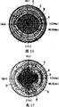
本发明人已经验证,采用上述结构的视角控制元件20是可以对透射光的射出角度进行控制的,现参考图3及图4对该验证结果进行说明。The inventors of the present invention have verified that the viewing
图3、图4为改变测量角度进行测量后所得到的视角控制元件20的透射率的分布图。FIG. 3 and FIG. 4 are distribution diagrams of the transmittance of the viewing
测量方法是:在如图1(b)所示的视角控制元件20的背面一侧(图中的下面一侧)配置面状光源,同时在视角控制元件20的图示上方配置检测器,在点亮前述面状光源的状态下,边改变检测器的测量角度(视角控制元件20的法线方向定为0°),边测量视角控制元件20的透射率。图3显示的是在如图1(b)所示的电极层26、28上未施加电压的状态下进行测量的结果,图4显示的是在前述电极层26、28上施加电压,使液晶层12的液晶分子的取向大致与基板24、25垂直的状态下进行测量的结果。另外,在图3、图4中是用符号A来表示透射率高的区域,符号B、C、D所表示的区域的透射率则按其顺序逐渐降低。The measurement method is: configure a planar light source on the back side (lower side in the figure) of the viewing
如图3所示,当未向电极层26、28施加电压时,可以在视角控制元件20的正面,在上下约60°、左右约40°的范围内全方位地获得很高的透射率。另一方面,如图4所示,在对电极层施加了电压时,在正面的上下方向的透射率分布情况和图3大致相同,而正面的左右方向的高角度侧的透射率则比图3所示的状态要低。从这些分布图可知,在本实施方式的视角控制元件20中,通过改变施加到电极层26、28上的电压的状态,就可既不损失从视角控制元件20的正面的、在上下方向上的亮度,又能使左右方向的透射光的射出角度变窄。As shown in FIG. 3 , when no voltage is applied to the electrode layers 26 and 28 , high transmittance can be obtained omnidirectionally in the range of about 60° up and down and about 40° left and right on the front of the viewing
因此,如果采用本实施方式的视角控制元件,则通过调整施加到液晶层的电压的状态即可随意地扩大、缩小相对于射出角度的透射率的分布,所以如果要在透过相关的视角控制元件的状态下显示种种的信息,则可随意改变前述信息的可视视角范围,有效地对第3者隐蔽信息,同时又能够给观看者本人提供良好的显示。Therefore, if the viewing angle control element of this embodiment is used, the distribution of the transmittance with respect to the emission angle can be arbitrarily expanded or reduced by adjusting the state of the voltage applied to the liquid crystal layer. By displaying various information in the state of the component, the viewing angle range of the aforementioned information can be changed at will, effectively hiding the information from the third party, and at the same time providing a good display for the viewer himself.
另外,在上述的实施方式中已对偏振层11、13的透射轴11p、13p分别和与液晶层的偏振层相邻接的液晶分子的取向方向12r1、12r2相互平行的情况做了说明,但对于制作视角控制元件时的这些轴和取向方向的配置来说,只要在实用上不存在什么问题的话,那么即使偏离了平行配置也不必介意。也就是说,在透射率的射出角度范围的确可控性和元件正面的透射率不会明显受到损失等情况下,可以调整上述的透射轴和液晶分子的配置。具体地说,就是如果透射轴11p与液晶分子的取向方向12r1所形成的角度以及透射轴13p与液晶分子的取向方向12r2所形成的角度是在±5°的范围内时,那么在实用上是不会有问题的。另外,如果液晶层12的液晶的扭转角是在180°±10°范围内,那么在实用上也没问题。In addition, in the above-mentioned embodiment, the case where the
(第2实施方式)(second embodiment)
下面将参照图5至图7对本发明的第2实施方式进行说明。图5表示的是本实施方式的视角控制元件的平面结构。本实施方式的视角控制元件30的基本结构与图1(a)所示的第一实施方式的视角控制元件10的基本结构是一样的。如图5所示,偏振层11的透射轴11p、偏振层13的透射轴13P是相互平行配置的,与液晶层12的偏振层11相邻接的液晶分子的取向方向12r1及与偏振层13相邻接的液晶分子的取向方向12r2是正交配置的。Next, a second embodiment of the present invention will be described with reference to FIGS. 5 to 7 . FIG. 5 shows the planar structure of the viewing angle control element of this embodiment. The basic structure of the viewing
可以使用图1(b)所示的结构来作为本实施方式的视角控制元件30的具体结构实例。即,在图1(b)所示的结构实例中,将偏振板21、23的透射轴从第1实施方式的配置位置旋转90°,就可作为具有图5所示的基本结构的视角控制元件。As a specific structural example of the viewing
和前述第1实施方式的情况一样,本发明人也对本实施方式的结构进行了视角控制元件的透射率的角度分布的测量,其测量的方法也与第1实施方式相同。图6是在未对液晶层施加电压的状态下的测量结果,图7是在对液晶层施加了电压的状态下(液晶分子处于相对偏振层11、13垂直取向的状态)的测量结果。As in the case of the aforementioned first embodiment, the present inventors also measured the angular distribution of the transmittance of the viewing angle control element in the structure of the present embodiment, and the measurement method is also the same as that of the first embodiment. FIG. 6 is the measurement result when no voltage is applied to the liquid crystal layer, and FIG. 7 is the measurement result when a voltage is applied to the liquid crystal layer (the liquid crystal molecules are aligned vertically to the
另外,图6及图7显示了A至D各区域的情况,如图6所示,在与相邻接的液晶分子的迟向轴平行地配置偏振层11、13时,在未对液晶层施加电压的状态下的透射光的射出角度的分布与图3所示的分布是一样的,能在较宽的角度范围内获得高透射率的A区,如图7所示,在对液晶层施加了电压的状态下,与图6中所示的分布相比,高透射率的区域A大幅度变窄。因此,采用具有本实施方式结构的视角控制元件也能随意扩大和缩小透射光的视角范围。In addition, Fig. 6 and Fig. 7 have shown the situation of each region A to D, as shown in Fig. 6, when disposing the
(第3实施方式)(third embodiment)
在前述实施方式的视角控制元件20中,为使正面观看时的显示亮度(透射率)达到最佳化,本发明人对构成视角控制元件20的液晶层12的液晶迟延Δnd作了变动,然后测量了视角控制元件20的正面透射率,图8就是表示其测量结果的曲线图,横轴为Δnd(μm)、纵轴为亮度(透射率)。如图8所示,相对于Δnd,视角控制元件30的正面亮度在呈周期性反复升降的同时也在逐渐增大。而且,从同图可知,如果Δnd大于等于1,则可在视角控制元件30的正面获得充分的亮度。另外,如果Δnd大于等于2,则即使改变Δnd,亮度也几乎不再发生变化,所以在正面观看的亮度稳定性方面比较理想。In the viewing
而且,本发明人对液晶层12的Δnd的改变所导致的前述视角限制效果(通过在液晶层12上施加电压所产生的视角窄化的效果)的变化也做了验证。Furthermore, the present inventors also verified the change of the aforementioned viewing angle limiting effect (the effect of narrowing the viewing angle by applying a voltage to the liquid crystal layer 12 ) caused by the change of Δnd of the
图9是表示对Δnd为1.0-8.0(μm)的8种液晶层12从视角控制元件的正面测量左右方向的亮度(透射率)所得到的结果的曲线图。横轴为从视角控制元件20的正面,在左右方向上的测量角度,纵轴为亮度(透射率)。另外,测量时施加在液晶层12上的电压为7V。如图9所示,在与本发明有关的视角控制元件20中,液晶层12的Δnd越大,明亮显示的角度范围就越窄,视角的限制效果得到增强。而另一方面,随着Δnd的不断增大,亮度的对称性(以0°为中心)有受到损害的趋势,尤其是在正视角侧的20°-30°附近亮度增大。因此,在进行视角限制时能够确保获得充分的视角的Δnd的范围在8.0um或以下,而同时还能得到亮度对称性的Δnd的范围在5.0μm或以下。9 is a graph showing the results of measuring the luminance (transmittance) in the left and right directions from the front of the viewing angle control element for eight kinds of liquid crystal layers 12 having Δnd of 1.0-8.0 (μm). The horizontal axis is the measurement angle in the left-right direction from the front of the viewing
上述的亮度非对称性是由于液晶层12的Δnd的增大而使对应于对液晶层12施加的电压的取向变化量减小的缘故。因此在无需考虑视角控制元件20的电能消耗的场合,如果通过对液晶层12施加更高的电压来确保亮度的对称性,那么当使用大于等于5μm的Δnd的液晶时也能获得良好的视角限制效果。The aforementioned brightness asymmetry is due to the increase in Δnd of the
(第4实施方式)(fourth embodiment)
下面将参照图10和图11对本发明的第4实施方式进行说明。图10和图11表示的是安有前述实施方式的视角控制元件20的显示装置的示意结构图。图10表示的是把视角控制元件20配置在显示元件35a的前面一侧(观察者0侧)的实例,图11表示的是把视角控制元件20配置在显示元件35b的背面侧(观察者0的反方向侧)的实例。Next, a fourth embodiment of the present invention will be described with reference to FIGS. 10 and 11 . FIG. 10 and FIG. 11 are schematic structural diagrams of a display device equipped with the viewing
首先,在如图10所示的显示装置中,使显示元件35a的显示光L透过视角控制元件20对观察者0进行显示。因此,通过对前述实施方式的视角控制元件20的液晶层12进行电控制,可随意扩大或缩小显示光L的射出角度(即视角)。因此,如果采用本实施方式的显示装置,则在通过视角控制元件20使显示光L处于窄视角的状态下可非常容易对第3者进行显示信息的隐蔽,而且在不需要这种信息保密的场合,不通过视角控制元件20对视角进行控制,所以可获得良好的视觉效果。First, in the display device shown in FIG. 10 , the display light L of the
上述的显示元件35a可以采用CRT(阴极射线管)显示元件、EL(电致发光)显示元件、PDP(等离子体显示面板)等发光型的显示元件或液晶显示元件等光栅型的显示元件。如图10所示,在把视角控制元件20配置在显示元件35a的前面的情况下,将发光型的显示元件或广视角的液晶显示元件作为显示元件35a使用时有非常好的效果。The above-mentioned
在如图11所示的显示装置中,预先用视角控制元件20对从光源等供给的光进行视角控制后使其入射到显示元件35b,从而对观察者0进行显示。本实施方式是采用液晶显示元件等光栅型显示元件作为显示元件35b的。若采用这种结构,则因为从观察者0处看时显示元件35b配置在最前面,所以具有无视觉差、显示清晰的优点。In the display device shown in FIG. 11 , the viewing
(第5实施方式)(fifth embodiment)
下面现参照图12及图13对本发明的第5实施方式进行说明。图12所示的显示装置具有从图示的上端开始依次将偏振层11、液晶层12、偏振层13a、液晶层36、偏振层38叠层的结构。即,图示上端的偏振层11、13a和夹在其间的液晶层12构成了具有与前述第1实施方式的视角控制元件10相同功能的视角控制元件,图示下端的偏振层13a、38和夹在其间的液晶层36构成了液晶显示元件。因此,偏振层13a由前述视角控制元件和液晶显示元件所共有。另外,在本实施方式中,示意性地示出的液晶显示元件仅由液晶层36和把其夹在中间的偏振层38、13a所构成,但实际上当然还应包含有用于驱动控制液晶取向的取向膜及电极、相位差层等。Next, a fifth embodiment of the present invention will be described with reference to FIGS. 12 and 13 . The display device shown in FIG. 12 has a structure in which a
上述结构的显示装置是通过液晶层36对从图示的下端(偏振层38的外侧)入射的光源等的光L进行调制后生成构成图像的显示光,然后对入射到液晶层12中的显示光的射出角度(视角)进行控制。与把作为不同的配件而准备的视角控制元件和液晶显示元件进行叠层而构成显示装置的情况相比,这种结构能实现显示装置的薄型化并可减少部件的个数,而且还能抑制因透过偏振层而造成的显示光的衰减,故能以较低的成本制作出明亮的薄型的显示装置。The display device with the above-mentioned structure modulates the light L of the light source or the like incident from the lower end (outside of the polarizing layer 38 ) of the figure through the
图13所示的显示装置具有从图示的上端开始依次将偏振层38、液晶层36、偏振层11a、液晶层12、偏振层13叠层的结构。即,图示下端的偏振层11a、13以及夹在其间的液晶层12构成了具有与前述第1实施方式的视角控制元件10相同功能的视角控制元件;图示上端的偏振层38、11a以及夹在其间的液晶层36构成了液晶显示元件。因此,偏振层11a由前述液晶显示元件及视角控制元件所共有。另外,在本实施方式中示意性地示出的液晶显示元件仅由液晶层36及将其夹在中间的偏振层11a、39所构成,但实际上当然还应包含有用于驱动控制液晶取向的取向膜和电极、相位差板等。The display device shown in FIG. 13 has a structure in which a polarizing layer 38 , a
上述结构的显示装置是首先通过液晶层12对从图示的下端(偏振层13的外侧)入射的光源等的光L的射出角度(视角)进行控制,然后再使之入射到液晶层36中,通过液晶层36进行调制而生成显示光,从而对观察者0进行显示。与把作为不同的部件而准备的视角控制元件及液晶显示元件进行叠层而构成显示装置的情况相比,这种结构也能实现显示装置的薄型化并可减少部件的个数,而且还能够抑制因透过偏振层而造成的显示光的衰减,故能以较低成本制作出明亮的薄型的显示装置。In the display device with the above-mentioned structure, the emission angle (viewing angle) of light L from a light source or the like incident from the lower end (outside of the polarizing layer 13) in the figure is first controlled through the
(第6实施方式)(sixth embodiment)
下面参照图14对本发明的第6实施方式进行说明。图14中显示有其剖面结构的本实施方式的显示装置是采用EL显示元件作为显示元件37的,在这EL显示元件37上安装有把圆偏振层13b、液晶层12和偏振层11进行叠层配置的视角控制元件。在前述EL显示元件37上所配置的视角控制元件除了将圆偏振层13b配置在其一侧的面上外,其它的功能均和前述第1实施方式的视角控制元件10相同。这样,使来自EL显示元件37的显示光L入射到上述的视角控制元件上,通过相关的视角控制元件进行视角控制后到达观察者0,从而进行显示。Next, a sixth embodiment of the present invention will be described with reference to FIG. 14 . The display device of the present embodiment whose cross-sectional structure is shown in FIG. The viewing angle control element for the layer configuration. The viewing angle control element disposed on the EL display element 37 has the same functions as the viewing angle control element 10 of the first embodiment except that the circular polarizing layer 13b is disposed on one side thereof. In this way, the display light L from the EL display element 37 is incident on the above-mentioned viewing angle control element, and the viewing angle is controlled by the related viewing angle control element, and reaches the
在上述结构的显示装置中,设置在EL显示元件37和液晶层12之间的圆偏振层13b是用来消除EL显示元件的镜面效应,从而起到提高显示装置的视觉效果的作用的。这个圆偏振层13b可以使用例如叠层有相位差层和偏振层的光学薄膜等材料,在本结构中是把前述相位差层配置在EL显示元件37一侧,把上述的偏振层配置在液晶层12一侧。In the display device with the above structure, the circular polarizing layer 13b disposed between the EL display element 37 and the
(第7实施方式)(seventh embodiment)
下面将参照图15至图17对本发明的第7实施方式进行说明。图15中显示有其剖面结构的本实施方式的显示装置是把具有偏振层11、13以及夹在其间的液晶层12的视角控制元件10以及具有偏振层38、39及夹在其间的液晶层36的液晶显示元件35隔着旋光元件(旋光部件)40叠层配置而成。本实施方式的显示装置是通过视角控制元件10对入射到视角控制元件10的光源等的光L进行视角控制后使其入射到旋光元件40。然后,通过该旋光元件40使前述光L的偏振方向旋转,在液晶显示元件35的偏振层38的透射轴和前述偏振方向达到一致的状态下向液晶显示元件35入射。Next, a seventh embodiment of the present invention will be described with reference to FIGS. 15 to 17 . The display device of the present embodiment whose cross-sectional structure is shown in FIG. 36 liquid crystal display elements 35 are stacked and arranged with an optical rotator (optical rotator) 40 interposed therebetween. In the display device of the present embodiment, the viewing angle control element 10 controls the viewing angle of light L from a light source or the like incident on the viewing angle controlling element 10 , and then makes it incident on the
因此,如果采用本实施方式的显示装置,则由于透过视角控制元件10的光L入射到液晶显示元件35时不会因偏振层38而产生吸收,故可使显示明亮。Therefore, according to the display device of this embodiment, the light L transmitted through the viewing angle control element 10 is not absorbed by the polarizing layer 38 when it enters the liquid crystal display element 35, so that the display can be bright.
在本实施方式的显示装置中,由于可对视角控制元件10的偏振层的透射轴的方向进行任意取向而并不仅限于液晶显示元件35的透射轴的方向,例如,即使把液晶显示元件35的偏振层38、39配置成与能获得高对比度显示的方向相一致的方向,也可使进行视角控制的视角控制元件10的偏振层11、13的方向与适宜进行视角控制的方向一致,所以可以一并获得显示的高质量和良好的视角控制功能。In the display device of this embodiment, since the direction of the transmission axis of the polarizing layer of the viewing angle control element 10 can be arbitrarily oriented, it is not limited to the direction of the transmission axis of the liquid crystal display element 35. For example, even if the direction of the transmission axis of the liquid crystal display element 35 is The polarizing layers 38, 39 are disposed in a direction consistent with the direction in which a high-contrast display can be obtained, and the direction of the
在本实施方式中,对从观察者0看把视角控制元件10配置在液晶显示元件35的背面一侧的情况进行了说明,但是,将这些视角控制元件10与液晶显示元件35的位置关系颠倒也没关系。为要获得更加清晰的显示效果,还是最好像本实施方式那样,把液晶显示元件35配置在观察者0侧较为理想,但由于采用视角控制元件10进行的视角控制,需在用液晶显示元件35进行光调制之前进行,因而在高角度侧进行的显示稍有些暗,所以最好事先考虑好显示的亮度和清晰度后再决定如何配置液晶显示元件35和视角控制元件10。下面参照图片对采用这些配置的视角特性的区别进行说明。In this embodiment, the case where the viewing angle control element 10 is arranged on the rear side of the liquid crystal display element 35 as viewed from the
图16及图17是改变测量角度进行测量后所得到的本实施方式的显示装置的透射率的分布图。测量方法与前述第1实施方式相同。图16是在液晶层12上未施加电压的状态下的测量结果,图17是对液晶层12施加了电压的状态下的测量结果。如这些图所示,在本实施方式的显示装置中,也可以通过改变施加于液晶层12的电压状态,很容易地进行宽视角、窄视角的显示的切换。16 and 17 are distribution diagrams of the transmittance of the display device according to the present embodiment obtained by measuring with different measurement angles. The measurement method is the same as that of the first embodiment described above. FIG. 16 shows measurement results in a state where no voltage is applied to the
与此相对,在把视角控制元件10配置在液晶显示元件35的前面一侧(观察者0侧)的场合可以获得如图3、4所示的视角特性,因此,如果把图3和图16做一比较的话,则可看出在不施加电压的状态下将视角控制元件10配置在液晶显示元件35的前面一侧时,可以在很宽的视角范围内获得明亮的显示。但由于是把视角控制元件10配置在前面一侧,所以显示的清晰度会下降。On the other hand, when the viewing angle control element 10 is arranged on the front side (
作为与本实施方式相关的旋光元件40可以使用,例如,具有面内相位差的相位差薄膜或由这样的相位差薄膜的叠层体所构成的1/2波长板。As the
另外,前述旋光元件40也可使用配置有在元件的厚度方向上具有扭曲结构的液晶的元件。在这种场合,前述扭曲结构的扭转角度是指视角控制元件10的偏振层11的光轴方向与液晶显示元件35的偏振层38的光轴方向所形成的夹角,上述液晶的Δnd(μm)要大于前述偏振层11、38的光轴相互之间所形成的夹角的1/200。In addition, as the
(第8实施方式)(eighth embodiment)
下面参照图19至图21对本发明的第8实施方式进行说明。图19中显示有其剖面结构的本实施方式的视角控制元件具有偏振层11、13及夹在其间的相位差层14、15及液晶层12,和前面的实施方式一样,例如,可以配置在液晶显示元件20的前面一侧。液晶层12是由取向扭转180°的液晶所构成的,偏振层11、13的透射轴相互平行。另外,液晶层12的偏振层11一侧的液晶分子与偏振层11的透射轴平行配置,偏振层13一侧的液晶分子与偏振层13的透射轴平行配置。也就是说,除配置了相位差层14、15之外,本实施方式的视角控制元件50的其它结构均与上述第1实施方式的视角控制元件相同。Next, an eighth embodiment of the present invention will be described with reference to FIGS. 19 to 21 . The viewing angle control element of the present embodiment whose cross-sectional structure is shown in FIG. The front side of the liquid
对于上述的相位差层14、15来说,最理想的是使用在其面方向上设有相位差而仅在层厚方向上有相位差,且层厚方向的折射率比面方面的折射率小的相位差薄膜(膜厚方向上有光轴的相位差薄膜、即所谓的C片)。若将这样的相位差层的层厚方向的折射率具体表示的话,那么当把相位差薄膜的面方向上的折射率表示为nx、ny,把层厚(垂直)方向上的折射率表示为nz时,则层厚方向上的相位差就是:层厚d×((nx+ny)/2-nz)。For the above-mentioned retardation layers 14, 15, it is most desirable to use a layer with a retardation in the plane direction and a retardation only in the layer thickness direction, and the refractive index in the layer thickness direction is higher than the refractive index in the plane direction. Small retardation films (retardation films with an optical axis in the film thickness direction, so-called C plates). If the refractive index in the layer thickness direction of such a retardation layer is specifically expressed, then when the refractive index in the plane direction of the retardation film is expressed as nx, ny, the refractive index in the layer thickness (perpendicular) direction is expressed as nz, the phase difference in the layer thickness direction is: layer thickness d×((nx+ny)/2-nz).
另外,采用这样的相位差薄膜时,不必非要和偏振层11、13的光轴一致,有更加容易制作的优点。In addition, when such a retardation film is used, it is not necessary to coincide with the optical axes of the
另外,在本实施方式中,作为最理想的配置方式,说明了把液晶层12夹在相位差层14、15的中间,将相位差层14、15分别配置在其两侧的配置方式,但前述配置方式并非仅限于此。也就是说,可以把单一的相位差层14配置在液晶层12与偏振层11之间,也可以在液晶层12与偏振层11之间重叠配置两层相位差层14、15。如果使用两层或以上的相位差层,则可在扩大视角控制范围的同时,还能使面方向上的相位差互相补偿,使视角特性的对称性得到提高。而且还可根据情况使用设置有3层或以上相位差层的方式。In addition, in the present embodiment, as the most ideal arrangement, the arrangement in which the
由于在配有上述结构的本实施方式的视角控制元件50中设置了上述的相位差层14、15,所以特别是可将视角限制时的视角范围收得很窄。Since the above-described retardation layers 14 and 15 are provided in the viewing angle control element 50 of the present embodiment having the above-mentioned structure, it is possible to narrow the range of the viewing angle particularly when the viewing angle is limited.
图20显示了把本实施方式的视角控制元件50配置在前述液晶显示元件20的前面一侧的状态下所测得的透射率的分布。图21是为了进行对比而示出的和第1实施方式相关的视角控制元件10的液晶层的Δnd为2.0时的透射率分布的图。图20和图21中用符号E表示的空白区域是透射率(亮度)在正面方向(分布图的中心)透射率成为10%或以下的区域,因此,在这些E区域的显示非常暗,几乎看不清背面侧的液晶显示元件20的显示内容。FIG. 20 shows the distribution of transmittance measured in a state where the viewing angle control element 50 of this embodiment is arranged on the front side of the liquid
在图20及图21中所显示的透射率分布的测量方法与前述第1实施方式的测量方法相同,测量时所用的偏振层14、15是在厚度方向上的相位差为2D0nm的C片。通过对2种透射率分布进行的比较可知,拥有将相位差层14、15配置在偏振层11、12内侧的视角控制元件50(图20)的显示装置,它的E区要比拥有前述实施方式的视角控制元件10的显示装置的E区大,所以能够在更宽的视角范围内对显示内容进行隐蔽,视角的控制性能更加出色。The measurement method of the transmittance distribution shown in FIG. 20 and FIG. 21 is the same as the measurement method of the aforementioned first embodiment, and the polarizing layers 14 and 15 used in the measurement are C plates with a retardation of 2D0 nm in the thickness direction. By comparing the two kinds of transmittance distributions, it can be known that the display device with the viewing angle control element 50 (FIG. 20) having the retardation layer 14, 15 arranged inside the
(电子设备)(Electronic equipment)
图18是表示与本发明有关的一例电子设备的立体图。图中所示的便携式电话1300是把本发明的显示装置作为小尺寸的显示部1301而安装的,它拥有多个操作键1302、接听口1303和送话口1304。Fig. 18 is a perspective view showing an example of electronic equipment related to the present invention. The mobile phone 1300 shown in the figure is equipped with the display device of the present invention as a small-sized display portion 1301, and has a plurality of operation keys 1302, a receiving port 1303 and a speaking port 1304.
上述的各实施方式的显示装置并不仅限于用在上述的便携式电话,可用作像电子图书、个人计算机、数码相机、液晶电视、取景器型或监控直视型视频信号记录器、汽车驾驶向导装置、传呼机、电子记事本、计算器、文字处理机、工作站、可视电话、POS终端、带触摸面板的设备等的图像显示部件,不管用于哪种电子设备,都能很容易地实现广视角与窄视角之间的切换,可以获得出色的信息隐蔽性及高质量的显示。The display devices of the above-mentioned embodiments are not limited to the above-mentioned mobile phones, and can be used as electronic books, personal computers, digital cameras, liquid crystal televisions, viewfinder-type or monitor direct-view video signal recorders, and car driving guides. Devices, pagers, electronic notebooks, calculators, word processors, workstations, videophones, POS terminals, equipment with touch panels, etc., can be easily realized regardless of the electronic equipment used Switching between wide viewing angle and narrow viewing angle can obtain excellent information concealment and high-quality display.
Claims (20)
Applications Claiming Priority (4)
| Application Number | Priority Date | Filing Date | Title |
|---|---|---|---|
| JP131672/2003 | 2003-05-09 | ||
| JP2003131672 | 2003-05-09 | ||
| JP025421/2004 | 2004-02-02 | ||
| JP2004025421A JP3823972B2 (en) | 2003-05-09 | 2004-02-02 | Viewing angle control element, display device, and electronic device |
Related Child Applications (1)
| Application Number | Title | Priority Date | Filing Date |
|---|---|---|---|
| CNB2007101126045A Division CN100535722C (en) | 2003-05-09 | 2004-05-09 | Viewing angle control element, display device, and electronic apparatus |
Publications (2)
| Publication Number | Publication Date |
|---|---|
| CN1550840A CN1550840A (en) | 2004-12-01 |
| CN1332256C true CN1332256C (en) | 2007-08-15 |
Family
ID=32993123
Family Applications (1)
| Application Number | Title | Priority Date | Filing Date |
|---|---|---|---|
| CNB2004100347333A Expired - Lifetime CN1332256C (en) | 2003-05-09 | 2004-05-09 | Viewing angle control element, display device, and electronic apparatus |
Country Status (7)
| Country | Link |
|---|---|
| US (1) | US7400367B2 (en) |
| EP (1) | EP1475655B1 (en) |
| JP (1) | JP3823972B2 (en) |
| KR (1) | KR100685569B1 (en) |
| CN (1) | CN1332256C (en) |
| DE (1) | DE602004002315T2 (en) |
| TW (1) | TW200508697A (en) |
Families Citing this family (44)
| Publication number | Priority date | Publication date | Assignee | Title |
|---|---|---|---|---|
| US7683875B2 (en) * | 2003-03-31 | 2010-03-23 | Sharp Kabushiki Kaisha | Liquid crystal display device and electronic device |
| GB2413394A (en) * | 2004-04-20 | 2005-10-26 | Sharp Kk | Display |
| JP4668549B2 (en) * | 2004-04-21 | 2011-04-13 | 大日本印刷株式会社 | Optical compensation element with variable phase difference and liquid crystal display using the same |
| US20060044290A1 (en) * | 2004-08-24 | 2006-03-02 | Hurwitz Roger A | Electronic privacy filter |
| CN100428326C (en) * | 2004-08-30 | 2008-10-22 | 夏普株式会社 | Display control device, display device, control method of display device, display control program, and recording medium having the program recorded therein |
| WO2006025326A1 (en) * | 2004-08-31 | 2006-03-09 | Sharp Kabushiki Kaisha | Visibility angle control device, display device, control method of visibility angle control device, visibility angle control program, and recording medium having the program recorded therein |
| JP4494410B2 (en) * | 2004-09-07 | 2010-06-30 | シャープ株式会社 | Display device, viewing angle control device, and electronic device |
| WO2006030702A1 (en) * | 2004-09-15 | 2006-03-23 | Sharp Kabushiki Kaisha | Display, viewing angle controller and electronic apparatus |
| US8031273B2 (en) * | 2004-09-17 | 2011-10-04 | Sharp Kabushiki Kaisha | Display device, viewing angle control device, and electronic device |
| US8184145B2 (en) * | 2004-10-04 | 2012-05-22 | Sharp Kabushiki Kaisha | Display device and electronic apparatus |
| CN101048727B (en) * | 2004-10-27 | 2010-09-29 | 富士通天株式会社 | display device |
| JP4536489B2 (en) | 2004-11-15 | 2010-09-01 | 株式会社 日立ディスプレイズ | Optical element and display device using the same |
| KR101205652B1 (en) * | 2005-04-01 | 2012-11-27 | 샤프 가부시키가이샤 | Mobile information terminal device, and display terminal device |
| JP2006330164A (en) * | 2005-05-24 | 2006-12-07 | Casio Comput Co Ltd | Liquid crystal display device |
| US7965268B2 (en) | 2005-07-08 | 2011-06-21 | Sharp Kabushiki Kaisha | Display device and liquid crystal display panel |
| KR101258591B1 (en) * | 2005-12-23 | 2013-05-02 | 엘지디스플레이 주식회사 | Liquid Crystal Display Device and Driving Method Thereof |
| KR100816078B1 (en) * | 2006-06-19 | 2008-03-24 | 광운대학교 산학협력단 | Spatial image projector and its method |
| WO2008004361A1 (en) * | 2006-07-05 | 2008-01-10 | Sharp Kabushiki Kaisha | Liquid crystal display and angle-of-field control panel |
| CN101427177B (en) * | 2006-08-09 | 2010-12-29 | 夏普株式会社 | Liquid crystal display device and viewing angle control module |
| JP5043019B2 (en) * | 2006-09-07 | 2012-10-10 | シャープ株式会社 | Liquid crystal display |
| JP4572888B2 (en) | 2006-10-30 | 2010-11-04 | ソニー株式会社 | Liquid crystal device and electronic device |
| GB2443648A (en) * | 2006-11-07 | 2008-05-14 | Sharp Kk | LC display having public and private viewing modes arranged to display a first image in the public mode and second and third spatially interlaced images in th |
| JP2008139769A (en) * | 2006-12-05 | 2008-06-19 | Tohoku Univ | Viewing angle control LCD panel |
| KR101476841B1 (en) * | 2006-12-28 | 2014-12-24 | 엘지디스플레이 주식회사 | Viewing angle control liquid crystal display |
| US8698988B2 (en) | 2007-01-09 | 2014-04-15 | Japan Display West Inc. | Liquid crystal device having viewing angle control pixels |
| JP2008275966A (en) * | 2007-05-01 | 2008-11-13 | Epson Imaging Devices Corp | Liquid crystal display device and electronic equipment |
| JP4794669B2 (en) * | 2007-05-21 | 2011-10-19 | シャープ株式会社 | Display and viewing angle control element used therefor |
| US20100149459A1 (en) * | 2007-07-09 | 2010-06-17 | Koji Yabuta | View angle control element and display device provided with the same |
| KR100869810B1 (en) | 2007-08-02 | 2008-11-21 | 삼성에스디아이 주식회사 | Display device |
| EP2199848A4 (en) * | 2007-10-18 | 2011-07-20 | Sharp Kk | Liquid crystal display device |
| CN101458411B (en) * | 2007-12-12 | 2012-08-29 | 奇美电子股份有限公司 | Liquid crystal display device with adjustable viewing angle |
| US8681294B2 (en) * | 2008-12-02 | 2014-03-25 | Hiap L. Ong & Kyoritsu Optronics Co., Ltd. | Optical compensation film for LCD viewing angles reduction |
| EP2685307B1 (en) * | 2011-03-11 | 2019-07-10 | Citizen Watch Co., Ltd. | Light modulation element and microscope device provided with light modulation element |
| EP2761367A4 (en) | 2011-09-30 | 2015-06-10 | 3M Innovative Properties Co | Electronically switchable privacy film and display device having same |
| KR20130048070A (en) * | 2011-11-01 | 2013-05-09 | 삼성디스플레이 주식회사 | Display apparatus |
| JP6359338B2 (en) * | 2014-05-22 | 2018-07-18 | スタンレー電気株式会社 | Liquid crystal display |
| CN106353941A (en) * | 2016-10-31 | 2017-01-25 | 亚世光电股份有限公司 | TFT (Thin Film Transistor) liquid crystal module capable of directly reversing view angle |
| WO2019135535A1 (en) | 2018-01-04 | 2019-07-11 | 주식회사 엘지화학 | Liquid crystal display device and manufacturing method thereof |
| CN110361883B (en) | 2018-03-26 | 2023-04-28 | 中强光电股份有限公司 | Anti-peeping control device and backlight module and display using same |
| CN208126055U (en) | 2018-04-28 | 2018-11-20 | 扬升照明股份有限公司 | Display device |
| US10739625B2 (en) * | 2018-08-29 | 2020-08-11 | Innolux Corporation | Display device |
| JP7312632B2 (en) * | 2019-07-17 | 2023-07-21 | 株式会社ジャパンディスプレイ | Optical element and liquid crystal display |
| JP7395328B2 (en) * | 2019-11-14 | 2023-12-11 | 株式会社ジャパンディスプレイ | Vehicle display device |
| JP2021156943A (en) * | 2020-03-25 | 2021-10-07 | 株式会社ジャパンディスプレイ | Display device, display device for vehicle, and vehicle |
Citations (10)
| Publication number | Priority date | Publication date | Assignee | Title |
|---|---|---|---|---|
| JPH07333640A (en) * | 1994-06-14 | 1995-12-22 | Toshiba Corp | Liquid crystal display element |
| JPH08136909A (en) * | 1994-09-02 | 1996-05-31 | Sharp Corp | Image display device |
| US5570211A (en) * | 1994-03-02 | 1996-10-29 | Fujitsu Limited | Color liquid crystal display device using birefringence |
| JPH0973070A (en) * | 1995-09-06 | 1997-03-18 | Seiko Epson Corp | Viewing angle limiting device and image display device using the same |
| JPH1039821A (en) * | 1996-04-19 | 1998-02-13 | Ncr Internatl Inc | Method for controlling visibility of display screen and device therefor |
| US5781265A (en) * | 1995-10-24 | 1998-07-14 | Samsung Display Devices Co., Ltd. | Non-chiral smectic C liquid crystal display |
| JPH11174489A (en) * | 1997-12-17 | 1999-07-02 | Matsushita Electric Ind Co Ltd | Liquid crystal display device |
| US6181309B1 (en) * | 1997-04-25 | 2001-01-30 | Optrex Corporation | Color liquid crystal display device |
| US6490076B2 (en) * | 2001-01-11 | 2002-12-03 | Hrl Laboratories, Llc | Optical phased array for depolarized optical beam control |
| JP2003015535A (en) * | 2001-07-03 | 2003-01-17 | Alpine Electronics Inc | Display device |
Family Cites Families (24)
| Publication number | Priority date | Publication date | Assignee | Title |
|---|---|---|---|---|
| US4927240A (en) * | 1983-11-02 | 1990-05-22 | Michael Stolov | Multiple liquid crystal display |
| JPS6146930A (en) | 1984-08-10 | 1986-03-07 | Ricoh Co Ltd | Liquid crystal display method and its display device |
| JPH0656459B2 (en) | 1985-04-05 | 1994-07-27 | 株式会社日立製作所 | Liquid crystal display element |
| JPS62143990A (en) * | 1985-12-18 | 1987-06-27 | Hitachi Ltd | Liquid crystal display element |
| KR900008302B1 (en) | 1987-12-30 | 1990-11-12 | 삼성전자 주식회사 | Power factor measuring circuit and method of power meter |
| JP2523811B2 (en) * | 1988-09-02 | 1996-08-14 | 株式会社日立製作所 | Liquid crystal light modulator |
| EP0367616A3 (en) * | 1988-11-04 | 1991-04-24 | Matsushita Electric Industrial Co., Ltd. | Optical liquid crystal element |
| JP2721284B2 (en) | 1991-02-07 | 1998-03-04 | 株式会社東芝 | Liquid crystal display element and optically anisotropic element |
| DE69226998T2 (en) * | 1991-07-19 | 1999-04-15 | Sharp K.K., Osaka | Optical modulation element and devices with such an element |
| JP3087861B2 (en) | 1991-10-14 | 2000-09-11 | 日本電信電話株式会社 | Viewing angle control type display device |
| US5572343A (en) * | 1992-05-26 | 1996-11-05 | Olympus Optical Co., Ltd. | Visual display having see-through function and stacked liquid crystal shutters of opposite viewing angle directions |
| JP3006643B2 (en) * | 1992-10-05 | 2000-02-07 | 富士通株式会社 | Liquid crystal display |
| US5680184A (en) * | 1994-04-12 | 1997-10-21 | Casio Computer Co., Ltd. | Color liquid crystal display device |
| US5751385A (en) * | 1994-06-07 | 1998-05-12 | Honeywell, Inc. | Subtractive color LCD utilizing circular notch polarizers and including a triband or broadband filter tuned light source or dichroic sheet color polarizers |
| JPH0943654A (en) * | 1995-07-31 | 1997-02-14 | Hitoshi Nitta | Parallel optical logic operation element and device |
| TW332870B (en) | 1995-08-17 | 1998-06-01 | Toshiba Co Ltd | LCD and optical anisotropy device |
| JPH10510671A (en) * | 1995-09-25 | 1998-10-13 | フィリップス エレクトロニクス ネムローゼ フェンノートシャップ | Electroluminescent illumination system and flat-panel image display device provided with such illumination system |
| KR100241816B1 (en) | 1995-11-24 | 2000-02-01 | 니시무로 타이죠 | Liquid crystal display device and optical isotropic device |
| JP2000047195A (en) | 1998-07-30 | 2000-02-18 | Casio Comput Co Ltd | Liquid crystal display device |
| US6642984B1 (en) * | 1998-12-08 | 2003-11-04 | Fujitsu Display Technologies Corporation | Liquid crystal display apparatus having wide transparent electrode and stripe electrodes |
| KR20000066806A (en) * | 1999-04-21 | 2000-11-15 | 구본준 | Liquid Crystal Display having a convertible mode between wide viewing angle and narrow viewing angle |
| KR100695297B1 (en) * | 2000-06-13 | 2007-03-14 | 삼성전자주식회사 | Wide viewing angle liquid crystal display using compensation film |
| JP2002297044A (en) | 2001-03-29 | 2002-10-09 | Toshiba Corp | Mobile display for narrow angle of view, manufacturing method for filter used in the display, and portable terminal device |
| JP2004062094A (en) | 2002-07-31 | 2004-02-26 | Sony Ericsson Mobilecommunications Japan Inc | Mobile terminal system and visual field angle variable display device |
-
2004
- 2004-02-02 JP JP2004025421A patent/JP3823972B2/en not_active Expired - Lifetime
- 2004-04-27 US US10/832,275 patent/US7400367B2/en not_active Expired - Lifetime
- 2004-04-28 DE DE602004002315T patent/DE602004002315T2/en not_active Expired - Lifetime
- 2004-04-28 EP EP04252464A patent/EP1475655B1/en not_active Expired - Lifetime
- 2004-05-05 TW TW093112678A patent/TW200508697A/en not_active IP Right Cessation
- 2004-05-07 KR KR1020040032356A patent/KR100685569B1/en active IP Right Grant
- 2004-05-09 CN CNB2004100347333A patent/CN1332256C/en not_active Expired - Lifetime
Patent Citations (10)
| Publication number | Priority date | Publication date | Assignee | Title |
|---|---|---|---|---|
| US5570211A (en) * | 1994-03-02 | 1996-10-29 | Fujitsu Limited | Color liquid crystal display device using birefringence |
| JPH07333640A (en) * | 1994-06-14 | 1995-12-22 | Toshiba Corp | Liquid crystal display element |
| JPH08136909A (en) * | 1994-09-02 | 1996-05-31 | Sharp Corp | Image display device |
| JPH0973070A (en) * | 1995-09-06 | 1997-03-18 | Seiko Epson Corp | Viewing angle limiting device and image display device using the same |
| US5781265A (en) * | 1995-10-24 | 1998-07-14 | Samsung Display Devices Co., Ltd. | Non-chiral smectic C liquid crystal display |
| JPH1039821A (en) * | 1996-04-19 | 1998-02-13 | Ncr Internatl Inc | Method for controlling visibility of display screen and device therefor |
| US6181309B1 (en) * | 1997-04-25 | 2001-01-30 | Optrex Corporation | Color liquid crystal display device |
| JPH11174489A (en) * | 1997-12-17 | 1999-07-02 | Matsushita Electric Ind Co Ltd | Liquid crystal display device |
| US6490076B2 (en) * | 2001-01-11 | 2002-12-03 | Hrl Laboratories, Llc | Optical phased array for depolarized optical beam control |
| JP2003015535A (en) * | 2001-07-03 | 2003-01-17 | Alpine Electronics Inc | Display device |
Also Published As
| Publication number | Publication date |
|---|---|
| JP3823972B2 (en) | 2006-09-20 |
| US20040252258A1 (en) | 2004-12-16 |
| CN1550840A (en) | 2004-12-01 |
| DE602004002315T2 (en) | 2007-09-20 |
| DE602004002315D1 (en) | 2006-10-26 |
| KR100685569B1 (en) | 2007-02-22 |
| TW200508697A (en) | 2005-03-01 |
| TWI326367B (en) | 2010-06-21 |
| JP2004361917A (en) | 2004-12-24 |
| EP1475655A1 (en) | 2004-11-10 |
| KR20040095736A (en) | 2004-11-15 |
| US7400367B2 (en) | 2008-07-15 |
| EP1475655B1 (en) | 2006-09-13 |
Similar Documents
| Publication | Publication Date | Title |
|---|---|---|
| CN1332256C (en) | Viewing angle control element, display device, and electronic apparatus | |
| JP4704349B2 (en) | Display device, viewing angle control device, and electronic device | |
| US7834834B2 (en) | Display device, viewing angle control device, and electronic apparatus | |
| US20090174843A1 (en) | Liquid crystal display device and viewing angle control module | |
| JPWO2018221413A1 (en) | Display device | |
| JP2009020293A (en) | Display and viewing angle control device used for the same | |
| US7639328B2 (en) | Viewing angle controllable liquid crystal display device | |
| US9099048B2 (en) | Liquid crystal device and electronic apparatus | |
| JPWO2008004361A1 (en) | Liquid crystal display device and viewing angle control panel | |
| JP2006350106A (en) | Liquid crystal display device | |
| US8184145B2 (en) | Display device and electronic apparatus | |
| JPWO2007138731A1 (en) | Liquid crystal display | |
| JP2008096458A (en) | Display and viewing angle controller to be used for the same | |
| JP5252335B2 (en) | Liquid crystal display device and terminal device | |
| JP4347163B2 (en) | Display device and electronic device | |
| JP2008064790A (en) | Display, and viewing angle controller used therefor | |
| WO2019103012A1 (en) | Display device | |
| CN214540287U (en) | Peep-proof display device | |
| JP4046116B2 (en) | Liquid crystal device and electronic device | |
| US8203671B2 (en) | View angle controllable display device and terminal having the same | |
| JP4470904B2 (en) | Viewing angle control element, display device, and electronic device | |
| JP2008165043A (en) | Liquid crystal display element | |
| JP2008051993A (en) | Electro-optical device, viewing angle control element, and electronic apparatus | |
| JP4788247B2 (en) | Liquid crystal device and electronic device | |
| CN101067695A (en) | View angle control element, display device and electronic equipment |
Legal Events
| Date | Code | Title | Description |
|---|---|---|---|
| C06 | Publication | ||
| PB01 | Publication | ||
| C10 | Entry into substantive examination | ||
| SE01 | Entry into force of request for substantive examination | ||
| C14 | Grant of patent or utility model | ||
| GR01 | Patent grant | ||
| C41 | Transfer of patent application or patent right or utility model | ||
| TR01 | Transfer of patent right |
Effective date of registration: 20160601 Address after: 100015 Jiuxianqiao Road, Beijing, No. 10, No. Patentee after: BOE TECHNOLOGY GROUP Co.,Ltd. Address before: Hongkong, China Patentee before: BOE Technology (Hongkong) Co.,Ltd. Effective date of registration: 20160601 Address after: Hongkong, China Patentee after: BOE Technology (Hongkong) Co.,Ltd. Address before: Tokyo, Japan Patentee before: Seiko Epson Corp. |
|
| CX01 | Expiry of patent term | ||
| CX01 | Expiry of patent term |
Granted publication date: 20070815 |