CN1331697C - General drive control method and general drive control method - Google Patents
General drive control method and general drive control method Download PDFInfo
- Publication number
- CN1331697C CN1331697C CNB038220431A CN03822043A CN1331697C CN 1331697 C CN1331697 C CN 1331697C CN B038220431 A CNB038220431 A CN B038220431A CN 03822043 A CN03822043 A CN 03822043A CN 1331697 C CN1331697 C CN 1331697C
- Authority
- CN
- China
- Prior art keywords
- actuators
- power
- work
- driving
- vehicle
- Prior art date
- Legal status (The legal status is an assumption and is not a legal conclusion. Google has not performed a legal analysis and makes no representation as to the accuracy of the status listed.)
- Expired - Fee Related
Links
- 238000000034 method Methods 0.000 title claims abstract description 57
- 238000005265 energy consumption Methods 0.000 claims description 30
- 238000003860 storage Methods 0.000 claims description 21
- 238000004146 energy storage Methods 0.000 claims description 12
- 230000008859 change Effects 0.000 claims description 11
- 238000001514 detection method Methods 0.000 claims 3
- 230000003247 decreasing effect Effects 0.000 abstract description 6
- 239000000446 fuel Substances 0.000 description 21
- 238000010248 power generation Methods 0.000 description 19
- 230000001133 acceleration Effects 0.000 description 18
- 230000007423 decrease Effects 0.000 description 17
- 230000006870 function Effects 0.000 description 16
- 238000009826 distribution Methods 0.000 description 13
- 238000010586 diagram Methods 0.000 description 12
- 230000008929 regeneration Effects 0.000 description 12
- 238000011069 regeneration method Methods 0.000 description 12
- 230000005540 biological transmission Effects 0.000 description 9
- 230000005611 electricity Effects 0.000 description 9
- 230000007246 mechanism Effects 0.000 description 8
- 230000001172 regenerating effect Effects 0.000 description 8
- 230000000694 effects Effects 0.000 description 5
- 230000007704 transition Effects 0.000 description 4
- 230000015556 catabolic process Effects 0.000 description 3
- 238000006731 degradation reaction Methods 0.000 description 3
- 230000009471 action Effects 0.000 description 2
- 238000002485 combustion reaction Methods 0.000 description 2
- 239000012530 fluid Substances 0.000 description 2
- 239000002828 fuel tank Substances 0.000 description 2
- 238000005457 optimization Methods 0.000 description 2
- 238000011084 recovery Methods 0.000 description 2
- UUDAMDVQRQNNHZ-UHFFFAOYSA-N (S)-AMPA Chemical compound CC=1ONC(=O)C=1CC(N)C(O)=O UUDAMDVQRQNNHZ-UHFFFAOYSA-N 0.000 description 1
- UFHFLCQGNIYNRP-UHFFFAOYSA-N Hydrogen Chemical compound [H][H] UFHFLCQGNIYNRP-UHFFFAOYSA-N 0.000 description 1
- 238000010420 art technique Methods 0.000 description 1
- 238000004364 calculation method Methods 0.000 description 1
- 238000006243 chemical reaction Methods 0.000 description 1
- 230000003750 conditioning effect Effects 0.000 description 1
- 238000001816 cooling Methods 0.000 description 1
- 230000001419 dependent effect Effects 0.000 description 1
- 229910052739 hydrogen Inorganic materials 0.000 description 1
- 239000001257 hydrogen Substances 0.000 description 1
- 238000004519 manufacturing process Methods 0.000 description 1
- 239000011159 matrix material Substances 0.000 description 1
- 238000012544 monitoring process Methods 0.000 description 1
- 230000008569 process Effects 0.000 description 1
- 230000009467 reduction Effects 0.000 description 1
- 239000000126 substance Substances 0.000 description 1
- 238000011144 upstream manufacturing Methods 0.000 description 1
- XLYOFNOQVPJJNP-UHFFFAOYSA-N water Substances O XLYOFNOQVPJJNP-UHFFFAOYSA-N 0.000 description 1
- 238000005303 weighing Methods 0.000 description 1
Images


Classifications
-
- B—PERFORMING OPERATIONS; TRANSPORTING
- B60—VEHICLES IN GENERAL
- B60W—CONJOINT CONTROL OF VEHICLE SUB-UNITS OF DIFFERENT TYPE OR DIFFERENT FUNCTION; CONTROL SYSTEMS SPECIALLY ADAPTED FOR HYBRID VEHICLES; ROAD VEHICLE DRIVE CONTROL SYSTEMS FOR PURPOSES NOT RELATED TO THE CONTROL OF A PARTICULAR SUB-UNIT
- B60W50/00—Details of control systems for road vehicle drive control not related to the control of a particular sub-unit, e.g. process diagnostic or vehicle driver interfaces
-
- B—PERFORMING OPERATIONS; TRANSPORTING
- B60—VEHICLES IN GENERAL
- B60W—CONJOINT CONTROL OF VEHICLE SUB-UNITS OF DIFFERENT TYPE OR DIFFERENT FUNCTION; CONTROL SYSTEMS SPECIALLY ADAPTED FOR HYBRID VEHICLES; ROAD VEHICLE DRIVE CONTROL SYSTEMS FOR PURPOSES NOT RELATED TO THE CONTROL OF A PARTICULAR SUB-UNIT
- B60W10/00—Conjoint control of vehicle sub-units of different type or different function
- B60W10/24—Conjoint control of vehicle sub-units of different type or different function including control of energy storage means
- B60W10/26—Conjoint control of vehicle sub-units of different type or different function including control of energy storage means for electrical energy, e.g. batteries or capacitors
-
- B—PERFORMING OPERATIONS; TRANSPORTING
- B60—VEHICLES IN GENERAL
- B60K—ARRANGEMENT OR MOUNTING OF PROPULSION UNITS OR OF TRANSMISSIONS IN VEHICLES; ARRANGEMENT OR MOUNTING OF PLURAL DIVERSE PRIME-MOVERS IN VEHICLES; AUXILIARY DRIVES FOR VEHICLES; INSTRUMENTATION OR DASHBOARDS FOR VEHICLES; ARRANGEMENTS IN CONNECTION WITH COOLING, AIR INTAKE, GAS EXHAUST OR FUEL SUPPLY OF PROPULSION UNITS IN VEHICLES
- B60K6/00—Arrangement or mounting of plural diverse prime-movers for mutual or common propulsion, e.g. hybrid propulsion systems comprising electric motors and internal combustion engines ; Control systems therefor, i.e. systems controlling two or more prime movers, or controlling one of these prime movers and any of the transmission, drive or drive units
- B60K6/20—Arrangement or mounting of plural diverse prime-movers for mutual or common propulsion, e.g. hybrid propulsion systems comprising electric motors and internal combustion engines ; Control systems therefor, i.e. systems controlling two or more prime movers, or controlling one of these prime movers and any of the transmission, drive or drive units the prime-movers consisting of electric motors and internal combustion engines, e.g. HEVs
- B60K6/42—Arrangement or mounting of plural diverse prime-movers for mutual or common propulsion, e.g. hybrid propulsion systems comprising electric motors and internal combustion engines ; Control systems therefor, i.e. systems controlling two or more prime movers, or controlling one of these prime movers and any of the transmission, drive or drive units the prime-movers consisting of electric motors and internal combustion engines, e.g. HEVs characterised by the architecture of the hybrid electric vehicle
- B60K6/48—Parallel type
-
- B—PERFORMING OPERATIONS; TRANSPORTING
- B60—VEHICLES IN GENERAL
- B60L—PROPULSION OF ELECTRICALLY-PROPELLED VEHICLES; SUPPLYING ELECTRIC POWER FOR AUXILIARY EQUIPMENT OF ELECTRICALLY-PROPELLED VEHICLES; ELECTRODYNAMIC BRAKE SYSTEMS FOR VEHICLES IN GENERAL; MAGNETIC SUSPENSION OR LEVITATION FOR VEHICLES; MONITORING OPERATING VARIABLES OF ELECTRICALLY-PROPELLED VEHICLES; ELECTRIC SAFETY DEVICES FOR ELECTRICALLY-PROPELLED VEHICLES
- B60L7/00—Electrodynamic brake systems for vehicles in general
- B60L7/10—Dynamic electric regenerative braking
-
- B—PERFORMING OPERATIONS; TRANSPORTING
- B60—VEHICLES IN GENERAL
- B60W—CONJOINT CONTROL OF VEHICLE SUB-UNITS OF DIFFERENT TYPE OR DIFFERENT FUNCTION; CONTROL SYSTEMS SPECIALLY ADAPTED FOR HYBRID VEHICLES; ROAD VEHICLE DRIVE CONTROL SYSTEMS FOR PURPOSES NOT RELATED TO THE CONTROL OF A PARTICULAR SUB-UNIT
- B60W30/00—Purposes of road vehicle drive control systems not related to the control of a particular sub-unit, e.g. of systems using conjoint control of vehicle sub-units
- B60W30/18—Propelling the vehicle
- B60W30/184—Preventing damage resulting from overload or excessive wear of the driveline
-
- B—PERFORMING OPERATIONS; TRANSPORTING
- B60—VEHICLES IN GENERAL
- B60K—ARRANGEMENT OR MOUNTING OF PROPULSION UNITS OR OF TRANSMISSIONS IN VEHICLES; ARRANGEMENT OR MOUNTING OF PLURAL DIVERSE PRIME-MOVERS IN VEHICLES; AUXILIARY DRIVES FOR VEHICLES; INSTRUMENTATION OR DASHBOARDS FOR VEHICLES; ARRANGEMENTS IN CONNECTION WITH COOLING, AIR INTAKE, GAS EXHAUST OR FUEL SUPPLY OF PROPULSION UNITS IN VEHICLES
- B60K1/00—Arrangement or mounting of electrical propulsion units
- B60K1/02—Arrangement or mounting of electrical propulsion units comprising more than one electric motor
-
- B—PERFORMING OPERATIONS; TRANSPORTING
- B60—VEHICLES IN GENERAL
- B60L—PROPULSION OF ELECTRICALLY-PROPELLED VEHICLES; SUPPLYING ELECTRIC POWER FOR AUXILIARY EQUIPMENT OF ELECTRICALLY-PROPELLED VEHICLES; ELECTRODYNAMIC BRAKE SYSTEMS FOR VEHICLES IN GENERAL; MAGNETIC SUSPENSION OR LEVITATION FOR VEHICLES; MONITORING OPERATING VARIABLES OF ELECTRICALLY-PROPELLED VEHICLES; ELECTRIC SAFETY DEVICES FOR ELECTRICALLY-PROPELLED VEHICLES
- B60L2200/00—Type of vehicles
- B60L2200/26—Rail vehicles
-
- B—PERFORMING OPERATIONS; TRANSPORTING
- B60—VEHICLES IN GENERAL
- B60L—PROPULSION OF ELECTRICALLY-PROPELLED VEHICLES; SUPPLYING ELECTRIC POWER FOR AUXILIARY EQUIPMENT OF ELECTRICALLY-PROPELLED VEHICLES; ELECTRODYNAMIC BRAKE SYSTEMS FOR VEHICLES IN GENERAL; MAGNETIC SUSPENSION OR LEVITATION FOR VEHICLES; MONITORING OPERATING VARIABLES OF ELECTRICALLY-PROPELLED VEHICLES; ELECTRIC SAFETY DEVICES FOR ELECTRICALLY-PROPELLED VEHICLES
- B60L2270/00—Problem solutions or means not otherwise provided for
- B60L2270/44—Heat storages, e.g. for cabin heating
-
- F—MECHANICAL ENGINEERING; LIGHTING; HEATING; WEAPONS; BLASTING
- F16—ENGINEERING ELEMENTS AND UNITS; GENERAL MEASURES FOR PRODUCING AND MAINTAINING EFFECTIVE FUNCTIONING OF MACHINES OR INSTALLATIONS; THERMAL INSULATION IN GENERAL
- F16H—GEARING
- F16H61/00—Control functions within control units of change-speed- or reversing-gearings for conveying rotary motion ; Control of exclusively fluid gearing, friction gearing, gearings with endless flexible members or other particular types of gearing
- F16H61/66—Control functions within control units of change-speed- or reversing-gearings for conveying rotary motion ; Control of exclusively fluid gearing, friction gearing, gearings with endless flexible members or other particular types of gearing specially adapted for continuously variable gearings
- F16H61/662—Control functions within control units of change-speed- or reversing-gearings for conveying rotary motion ; Control of exclusively fluid gearing, friction gearing, gearings with endless flexible members or other particular types of gearing specially adapted for continuously variable gearings with endless flexible members
-
- Y—GENERAL TAGGING OF NEW TECHNOLOGICAL DEVELOPMENTS; GENERAL TAGGING OF CROSS-SECTIONAL TECHNOLOGIES SPANNING OVER SEVERAL SECTIONS OF THE IPC; TECHNICAL SUBJECTS COVERED BY FORMER USPC CROSS-REFERENCE ART COLLECTIONS [XRACs] AND DIGESTS
- Y02—TECHNOLOGIES OR APPLICATIONS FOR MITIGATION OR ADAPTATION AGAINST CLIMATE CHANGE
- Y02T—CLIMATE CHANGE MITIGATION TECHNOLOGIES RELATED TO TRANSPORTATION
- Y02T10/00—Road transport of goods or passengers
- Y02T10/60—Other road transportation technologies with climate change mitigation effect
- Y02T10/62—Hybrid vehicles
-
- Y—GENERAL TAGGING OF NEW TECHNOLOGICAL DEVELOPMENTS; GENERAL TAGGING OF CROSS-SECTIONAL TECHNOLOGIES SPANNING OVER SEVERAL SECTIONS OF THE IPC; TECHNICAL SUBJECTS COVERED BY FORMER USPC CROSS-REFERENCE ART COLLECTIONS [XRACs] AND DIGESTS
- Y02—TECHNOLOGIES OR APPLICATIONS FOR MITIGATION OR ADAPTATION AGAINST CLIMATE CHANGE
- Y02T—CLIMATE CHANGE MITIGATION TECHNOLOGIES RELATED TO TRANSPORTATION
- Y02T10/00—Road transport of goods or passengers
- Y02T10/60—Other road transportation technologies with climate change mitigation effect
- Y02T10/72—Electric energy management in electromobility
Landscapes
- Engineering & Computer Science (AREA)
- Transportation (AREA)
- Mechanical Engineering (AREA)
- Chemical & Material Sciences (AREA)
- Combustion & Propulsion (AREA)
- Automation & Control Theory (AREA)
- Power Engineering (AREA)
- Human Computer Interaction (AREA)
- Electric Propulsion And Braking For Vehicles (AREA)
- Feedback Control In General (AREA)
- Control Of Vehicle Engines Or Engines For Specific Uses (AREA)
- Control Of Driving Devices And Active Controlling Of Vehicle (AREA)
- Air-Conditioning For Vehicles (AREA)
- Control Of Multiple Motors (AREA)
- Vehicle Body Suspensions (AREA)
Abstract
Description
技术领域technical field
本发明涉及一种在包括多个致动器和为所述致动器所共用的能源的机器中控制所述多个致动器的驱动的技术。更具体地说,本发明涉及一种从节约所述多个致动器所耗费的能量的观点来看用于使所述多个致动器的驱动最优化的技术。The invention relates to a technique for controlling the drive of a plurality of actuators in a machine comprising a plurality of actuators and an energy source common to said actuators. More specifically, the present invention relates to a technique for optimizing the driving of the plurality of actuators from the viewpoint of saving energy consumed by the plurality of actuators.
背景技术Background technique
在用于功的机器中,为了做功而耗费了能量。其所需的能量可从外部供应,或者所述机器自身可具有能源并且由其自身供应能量。In a machine for work, energy is expended in order to do work. The energy it requires can be supplied externally, or the machine can have its own energy source and be supplied with energy by itself.
在任何情况下,可由机器耗费的能量在必须节约资源和能量的当今世界中都是有限的。因此,在同一个机器中强烈期望实现目标操作(运行)状态并且同时节约所耗费的能量。In any event, the amount of energy that can be expended by a machine is limited in today's world where resources and energy must be conserved. Therefore, it is strongly desired to achieve a target operating (running) state and at the same time save consumed energy in the same machine.
可能存在其中所述机器具有多个致动器并且所述致动器被一起驱动这样一种情况。在这种情况下,实现目标操作状态并且同时节约能量消耗并非易事。理论上可将能源容量预设得甚至当所有致动器同时被驱动时也可防止耗竭。然而,从经济观点来看以及从诸如重量和尺寸等物理观点来看这不切合实际。There may be a situation where the machine has multiple actuators and the actuators are driven together. In this case, it is not easy to achieve the target operating state and at the same time save energy consumption. The energy capacity can theoretically be preset to prevent depletion even when all actuators are driven simultaneously. However, this is impractical from an economic point of view as well as from a physical point of view such as weight and size.
已经提出了用于综合管理作为机器的车辆中的多个致动器的一项技术(例如,在日本专利公开No.5-85228),所述车辆具有燃料作为能源以及具有发动机、制动器设备、转向装置等作为多个致动器。A technique for comprehensively managing a plurality of actuators in a vehicle as a machine having fuel as an energy source and having an engine, brake equipment, Steering devices and the like act as multiple actuators.
甚至当执行现有技术的技术时,当多个致动器一起被驱动时它们所耗费的能量总量也是无法估计的。因此,从节约能量消耗的观点来看,现有技术所涉及的技术不可能使得多个致动器的驱动最优化。Even when performing prior art techniques, the total amount of energy expended by multiple actuators when they are driven together is immeasurable. Therefore, from the standpoint of saving energy consumption, it is impossible for the related art to optimize the driving of a plurality of actuators.
因此,从节约所述多个致动器所消耗的能量的观点来看,本发明的一个目的是使得多个致动器的驱动最优化。It is therefore an object of the present invention to optimize the driving of the plurality of actuators from the point of view of saving the energy consumed by said plurality of actuators.
发明内容Contents of the invention
可以下述方式执行本发明。将作为独立方面描述这些方式,每个方面都将由一个方面标号表示,并且如果需要可参考其它方面的方面标号。所述描述用于帮助理解说明书中所述的技术特征和其组合,并且说明书中所述的技术特征和其组合不局限于以下方面。The present invention can be carried out in the following manner. These means will be described as independent aspects, each of which will be indicated by an aspect number, and reference will be made to the aspect numbers of other aspects if necessary. The description is for helping understanding of the technical features and combinations thereof described in the specification, and the technical features and combinations thereof described in the specification are not limited to the following aspects.
(1)一种设置在机器中的综合驱动控制系统,所述机器包括多个致动器和为所述致动器所共用的能源,并且所述机器通过消耗从所述能源供应的能量的多个致动器的操作做功量(amount of work)(下文中称为功),所述综合驱动控制系统包括(1) An integrated drive control system provided in a machine including a plurality of actuators and an energy source shared by the actuators, and the machine operates by consuming energy supplied from the energy source Amount of work (amount of work) (hereinafter referred to as work) of a plurality of actuators, the integrated drive control system includes
基于所述多个致动器中的每一个致动器的功率或功控制所述多个致动器的驱动的控制设备。A control device for controlling the actuation of the plurality of actuators based on the power or work of each of the plurality of actuators.
在本发明的系统中,考虑到所述多个致动器中的每一个致动器的功率或功,使得所述多个致动器的驱动被综合地控制。这里,在每个致动器的功率或功与能量消耗之间保持这样一种关系,即,功率或功越小,能量消耗越小。In the system of the present invention, the driving of the plurality of actuators is controlled comprehensively in consideration of the power or work of each of the plurality of actuators. Here, a relationship is maintained between the power or work and energy consumption of each actuator, that is, the smaller the power or work, the smaller the energy consumption.
因此,依照本发明的系统,当每个致动器的功率或功被注意时,从节约所述多个致动器所消耗的能量的观点来看,可使得多个致动器的驱动最优化。Therefore, according to the system of the present invention, when the power or work of each actuator is paid attention to, from the viewpoint of saving the energy consumed by the plurality of actuators, the drive of the plurality of actuators can be made the most efficient. optimization.
在本方面中,“致动器”可以是通过消耗电能作为能量而驱动的利用电磁力的力产生设备(诸如回转电动机或线性电动机),或者可以是通过消耗燃料作为能量而驱动的发动机。In this aspect, the "actuator" may be a force generating device using electromagnetic force, such as a rotary motor or a linear motor, driven by consuming electric energy as energy, or may be an engine driven by consuming fuel as energy.
这里,“电动机”可被看作是将电能转化为机械能的致动器,而“发动机”可被看作是将燃烧能转化为机械能的致动器。Here, an "electric motor" can be thought of as an actuator that converts electrical energy into mechanical energy, and an "engine" can be thought of as an actuator that converts combustion energy into mechanical energy.
在本方面中,“功率”是指每单位时间的功的量。当每个致动器将电能转化为机械能时,当从电能一方面(致动器的输入侧)看来,“功率”被表示为电力(电功率),而当从机械能一方面(致动器的输出侧)看来,“功率”可被表示为动态功率(功率或马力)。In this aspect, "power" refers to the amount of work per unit time. As each actuator converts electrical energy into mechanical energy, "power" is expressed as electrical power (electrical power) when viewed from the electrical energy side (the input side of the actuator), and when viewed from the mechanical energy side (the actuator's From the output side of ) view, "power" can be expressed as dynamic power (power or horsepower).
电力被计算为电压和电流的乘积。动态功率为机械功率,并且,诸如在车辆的情况中,当致动器使得机器本身移动时,将动态功率计算为由致动器施加在移动体上的力与移动体的速度的乘积。Electricity is calculated as the product of voltage and current. Dynamic power is mechanical power and is calculated as the force exerted by the actuator on the moving body multiplied by the speed of the moving body when the actuator moves the machine itself, such as in the case of a vehicle.
在本方面中,“功”是指功率的时间积分。当功率为电力时,功被表示为瓦特小时(或瓦特数W·h)。In this context, "work" refers to the time integral of power. When power is electricity, work is expressed as watt-hours (or wattage W·h).
在本方面中,“机器”可以为其自身可通过致动器的操作而运动的移动体,或者可以为用于移动与机器自身不同的目标的运动设备。In this aspect, the "machine" may be a moving body itself movable by the operation of an actuator, or may be a moving device for moving an object different from the machine itself.
(2)依照方面(1)所述的综合驱动控制系统,其中,所述控制设备基于作为在基本同一时期的多个致动器的功率或功的总和的总功率或总功综合地控制多个致动器的驱动。(2) The integrated drive control system according to aspect (1), wherein the control device comprehensively controls multiple actuators based on a total power or total work which is a sum of power or work of a plurality of actuators at substantially the same time period. drive of an actuator.
在该系统中,基于作为在基本同一时期的多个致动器的功率或功的总和的总功率或总功综合地控制多个致动器的驱动。In this system, driving of a plurality of actuators is comprehensively controlled based on total power or total work which is a sum of power or work of the plurality of actuators at substantially the same time period.
因此,依照本发明的系统,当多个致动器的总功率或总功被注意时,与节约所述多个致动器所消耗的能量相关,可使得多个致动器的驱动最优化。Thus, the system according to the invention makes it possible to optimize the drive of multiple actuators in relation to saving the energy consumed by said multiple actuators when the total power or total work of the multiple actuators is taken into account .
(3)依照方面(1)或(2)所述的综合驱动控制系统,其中,所述控制设备综合地控制多个致动器的驱动,以使得每个致动器的功率或功或者多个致动器的总功率或总功不会超过一容许值。(3) The comprehensive driving control system according to the aspect (1) or (2), wherein the control device comprehensively controls the driving of a plurality of actuators so that the power or work of each actuator is more or less The total power or total work of an actuator will not exceed an allowable value.
依照该系统,通过将每个致动器的功率或功或者多个致动器的总功率或总功与所述容许值相比较,可管理多个致动器所消耗的能量的总和。According to this system, by comparing the power or work of each actuator or the total power or work of the plurality of actuators with the allowable value, the sum of the energy consumed by the plurality of actuators can be managed.
(4)依照方面(3)所述的综合驱动控制系统,其中,所述控制设备包括功率限制单元,所述功率限制单元用于当总功率或总功将要超过所述容许值时,基于预先为多个致动器设定的顺序限制多个致动器中的至少一部分致动器的功率。(4) The integrated drive control system according to aspect (3), wherein the control device includes a power limiting unit configured to, when the total power or the total work is about to exceed the allowable value, The sequence set for the plurality of actuators limits the power of at least some of the plurality of actuators.
依照该系统,预先为多个致动器设定顺序,并且基于该顺序,限制多个致动器中的至少一部分致动器的功率。According to this system, an order is set in advance for the plurality of actuators, and based on the order, the power of at least some of the plurality of actuators is limited.
这里,可考虑每个致动器的功能·用法设定所述顺序。当所述机器为例如车辆时,可与每个致动器对于车辆的安全性的影响程度相关设定所述顺序。Here, the order may be set in consideration of the function and usage of each actuator. When the machine is, for example, a vehicle, the order may be set in relation to the degree of influence of each actuator on the safety of the vehicle.
因此,依照该方面的系统,基于预先设定的顺序,与致动器中的其它部分致动器的驱动相比较,多个致动器中的一部分致动器的驱动被限制,从而防止总功率或总功超过容许值。Therefore, according to the system of this aspect, the driving of a part of the plurality of actuators is restricted compared with the driving of other parts of the actuators based on a preset sequence, thereby preventing the overall The power or total work exceeds the allowable value.
因此,依照本发明的系统,更易于实现所述机器的目标操作状态并且同时节约能量消耗。Thus, according to the system of the invention, it is easier to achieve the target operating state of the machine and at the same time save energy consumption.
(5)依照方面(1)到(4)所述的综合驱动控制系统,还包括用于为机器确定(判定)驱动要求的驱动要求确定设备,其中所述控制设备将以所确定的驱动要求为基础的(基于所确定的驱动要求的)功率或功确定为所期望功率或所期望的功,并且基于所确定的期望功率或期望功综合地控制多个致动器的驱动。(5) The integrated drive control system according to aspects (1) to (4), further comprising a drive requirement determination device for determining (determining) a drive requirement for the machine, wherein the control device will The base (based on the determined driving requirement) power or work is determined as desired power or desired work, and driving of the plurality of actuators is comprehensively controlled based on the determined desired power or desired work.
在该系统中,每个致动器的目标值是从所述驱动要求中以功率或功为量度来表示和确定的,并且基于作为所确定的目标值的期望功率或期望功,综合地控制多个致动器的驱动。In this system, the target value of each actuator is expressed and determined in terms of power or work from the driving demand, and based on the desired power or desired work as the determined target value, comprehensively control Drive of multiple actuators.
因此,依照该系统,在满足节约能量消耗的需求的同时更易于满足驱动要求。Therefore, according to this system, it is easier to meet driving requirements while meeting the need to save energy consumption.
在该方面中,当机器为沿某一方向移动的移动体时,“驱动要求”是指,沿与所述移动体的前进方向平行或相交的方向作用在所述移动体上的力或加速度(或其变化量)、所述移动体的速度(或其变化量)、所述移动体的位置(或其变化量)或者所述移动体的移动方向(或其变化量)。In this aspect, when the machine is a moving body moving in a certain direction, the "driving requirement" refers to the force or acceleration acting on the moving body in a direction parallel to or intersecting the advancing direction of the moving body (or its variation), the speed of the moving body (or its variation), the position of the moving body (or its variation), or the moving direction of the moving body (or its variation).
(6)依照方面(5)所述的综合驱动控制系统,其中,所述驱动要求确定设备包括(6) The integrated driving control system according to aspect (5), wherein the driving requirement determination device includes
驱动信息检测器,它用于检测驾驶所述机器的驾驶员的指令、所述机器的操作状态或所述机器所处的操作环境中的至少一个作为驱动信息,以及a driving information detector for detecting, as driving information, at least one of a driver's instruction to drive the machine, an operating state of the machine, or an operating environment in which the machine is located, and
驱动要求确定单元,它用于基于所检测的驱动信息确定驱动要求,并且a driving requirement determination unit for determining a driving requirement based on the detected driving information, and
所述控制设备基于以所确定的驱动要求为基础的功率或功综合地控制多个致动器的驱动。The control device comprehensively controls the drive of the plurality of actuators based on the power or work based on the determined drive request.
在该系统中,基于驾驶所述机器的驾驶员的指令、所述机器的操作状态和所述机器所处的操作环境中的至少一个,确定用于所述机器的驱动要求。此外,基于以所确定的驱动要求为基础的每个致动器的功率或功,综合地控制多个致动器的驱动。In the system, a drive request for the machine is determined based on at least one of an instruction from a driver driving the machine, an operating state of the machine, and an operating environment in which the machine is located. Furthermore, the driving of the plurality of actuators is controlled comprehensively based on the power or work of each actuator based on the determined driving requirements.
因此,依照本发明的系统,从节约能量消耗的观点来看,考虑驾驶所述机器的驾驶员的指令、所述机器的操作状态和所述机器所处的操作环境中的至少一个,可使得多个致动器的驱动最优化。Therefore, according to the system of the present invention, considering at least one of the driver's instruction to drive the machine, the operating state of the machine, and the operating environment in which the machine is located, from the viewpoint of saving energy consumption, it is possible to make Drive optimization of multiple actuators.
(7)依照方面(5)或(6)所述的综合驱动控制系统,其中,所述控制设备基于所确定的驱动要求将满足驱动要求的功率或功确定为每个致动器的期望功率或期望功,并且基于所确定的期望功率或期望功,综合地控制多个致动器的驱动。(7) The integrated driving control system according to the aspect (5) or (6), wherein the control device determines power or work satisfying the driving requirement as desired power of each actuator based on the determined driving requirement or desired work, and based on the determined desired power or desired work, driving of the plurality of actuators is comprehensively controlled.
依照该系统,驱动要求和每个致动器以功率或功为量度的控制逻辑上彼此相关,因此,从功率或功的观点来看,每个致动器被驱动得满足所述驱动要求。According to this system, the drive requirements and the control of each actuator in terms of power or work are logically related to each other, so that each actuator is driven to meet said drive requirements from a power or work point of view.
因此,依照该系统,更易于满足所述驱动要求并且同时节约能量消耗。Therefore, according to this system, it is easier to meet said drive requirements and at the same time save energy consumption.
(8)依照方面(5)到(7)所述的综合驱动控制系统,其中,所述控制设备包括(8) The integrated drive control system according to aspects (5) to (7), wherein the control device includes
期望功率确定单元,它用于为每个致动器将满足所确定的驱动要求的功率确定为期望功率,a desired power determining unit for determining, for each actuator, power satisfying the determined driving requirement as desired power,
要求电力确定单元,它用于将要供应给每个致动器以便获得为每个致动器所确定的期望功率的电力确定为要求电力,a required power determination unit for determining, as the required power, power to be supplied to each actuator in order to obtain the desired power determined for each actuator,
期望功率建立单元,当作为为多个致动器确定的要求电力的总和的总要求电力超过所述容许值时,它用于通过减小所述多个致动器中的一些致动器的相应的期望功率而为各个致动器建立期望功率,以及a desired power establishing unit for, when the total required power which is the sum of the required power determined for the plurality of actuators exceeds the allowable value, by reducing the power of some of the plurality of actuators to establish a desired power for each actuator corresponding to the desired power, and
驱动单元,它用于基于所建立的期望功率驱动所述多个致动器。A drive unit for driving the plurality of actuators based on the established desired power.
依照该系统,通过在考虑驱动要求的同时限制一些致动器的功率的技术,更易于满足驱动要求并且同时节约能量消耗。According to this system, by the technique of limiting the power of some actuators while considering the driving requirement, it is easier to satisfy the driving requirement and save energy consumption at the same time.
(9)依照方面(8)所述的综合驱动控制系统,其中,所述期望功率建立单元当总要求电力超过所述容许值时基于预先为所述多个致动器设定的顺序,为一些致动器减小期望功率。(9) The integrated drive control system according to the aspect (8), wherein the expected power establishing unit is based on an order set in advance for the plurality of actuators when the total required power exceeds the allowable value, is Some actuators reduce the desired power.
依照该系统,可获得与方面(4)的系统所获得的那些相似的功能和效果。According to this system, functions and effects similar to those obtained by the system of aspect (4) can be obtained.
(10)依照方面(5)到(7)中任一项所述的综合驱动控制系统,其中,所述控制设备包括(10) The integrated drive control system according to any one of aspects (5) to (7), wherein the control device includes
期望功率确定单元,它用于为每个致动器将满足所确定的驱动要求的功率确定为期望功率,a desired power determining unit for determining, for each actuator, power satisfying the determined driving requirement as desired power,
要求功确定单元,它用于基于所确定的期望功率为每个致动器确定期望功,a required work determination unit for determining a desired work for each actuator based on the determined desired power,
总功确定单元,它用于将为多个致动器中的各个致动器确定的多个期望功的总和确定为总功,a total work determination unit for determining the sum of a plurality of expected works determined for each of the plurality of actuators as the total work,
期望功率建立单元,它用于当确定总功超过所述容许值时,通过减小所述多个致动器中的一些致动器的相应的期望功率而为每个致动器建立期望功率,以及a desired power establishing unit for establishing a desired power for each actuator by reducing the corresponding desired power of some of the plurality of actuators when the total work is determined to exceed the allowable value ,as well as
驱动单元,它用于基于所建立的期望功率驱动所述多个致动器。A drive unit for driving the plurality of actuators based on the established desired power.
在该系统中,通过限制一些致动器的功率的技术,基于基本与方面(8)的系统相似的机构,可满足驱动要求并且同时节约能量消耗。In this system, by a technique of limiting the power of some actuators, based on a mechanism basically similar to the system of aspect (8), the drive requirements can be met and at the same time save energy consumption.
在上述方面(8)所涉及的系统中,通过功率和容许值之间的比较节约了能量消耗,而在本方面的系统中,可通过功与容许值之间的比较节约能量消耗。In the system according to the above aspect (8), the energy consumption is saved by the comparison between the power and the allowable value, while in the system of this aspect, the energy consumption can be saved by the comparison between the work and the allowable value.
(11)依照方面(10)所述的综合驱动控制系统,其中,所述期望功建立单元当总功超过所述容许值时基于预先为所述多个致动器设定的顺序,为一些致动器减小期望功。(11) The integrated drive control system according to the aspect (10), wherein the expected work establishing unit is some The actuator reduces the desired work.
依照该系统,可获得与方面(4)的系统所获得的那些相似的功能和效果。According to this system, functions and effects similar to those obtained by the system of aspect (4) can be obtained.
(12)依照方面(10)或(11)所述的综合驱动控制系统,其中,所述驱动单元基于建立的期望功率为每个致动器将要供应给每个致动器的电力确定为供应电力,并且通过所确定的供应电力驱动每个致动器。(12) The integrated drive control system according to the aspect (10) or (11), wherein the drive unit determines, for each actuator, the electric power to be supplied to each actuator as the supply based on the established desired power. power, and drive each actuator with the determined power supply.
在该系统中,每个致动器都基于基于为每个致动器建立的期望功率所确定的供应电力被驱动。In this system, each actuator is driven based on supply power determined based on the desired power established for each actuator.
(13)依照方面(3)到(12)所述的综合驱动控制系统,其中,所述控制设备包括控制模式改变单元,它用于手动或自动改变所述容许值,以便改变用于控制所述多个致动器的控制模式。(13) The integrated drive control system according to aspects (3) to (12), wherein the control device includes a control mode changing unit for manually or automatically changing the allowable value so as to change the control modes for multiple actuators.
在方面(3)所涉及的系统中,所述多个致动器的驱动被综合地控制,以使得总功率或总功不会超过容许值。In the system according to aspect (3), the driving of the plurality of actuators is comprehensively controlled so that the total power or the total work does not exceed an allowable value.
这里,尽管所述容许值可被限定为固定值,但优选将其限定为可变值,以便灵活地满足故障要求、条件或环境。Here, although the allowable value may be defined as a fixed value, it is preferably defined as a variable value in order to flexibly meet failure requirements, conditions or circumstances.
使得所述容许值可变是指也使得用于控制所述多个致动器的控制模式可变。Making the allowable value variable means also making the control mode for controlling the plurality of actuators variable.
因此,在该方面所涉及的系统中,手动或自动改变所述容许值,从而改变用于控制所述多个致动器的控制模式。Therefore, in the system of this aspect, the allowable value is changed manually or automatically, thereby changing the control mode for controlling the plurality of actuators.
在该方面中,“控制模式改变单元”可以基于所述机器的操作状态自动地改变容许值的方式被操纵,或者可以基于所述机器所处的操作环境自动地改变容许值的方式被操纵。In this aspect, the "control mode changing unit" may be manipulated to automatically change the allowable value based on the operating state of the machine, or may be manipulated to automatically change the allowable value based on the operating environment in which the machine is placed.
当容许值为能源的剩余容量或为基于与剩余容量相关的物理值改变的可变量时,“控制模式改变单元”可以这样的方式被操纵,即,以剩余容量或相关物理值为基础的容许值的改变方案被手动或物理地改变。When the allowable value is the remaining capacity of energy or is a variable variable based on a change in a physical value related to the remaining capacity, the "control mode changing unit" can be manipulated in such a way that the allowable value based on the remaining capacity or the related physical value The value change scheme is changed manually or physically.
当术语“剩余容量”被定义为表示能源中剩余的电力的剩余量(例如,稍后将描述的电荷状态SOC)时,这里可将“相关物理量”定义为随着时间而减少的电力的剩余量的减少梯度。该梯度是指每单位时间电力的减少量,假定电力的剩余量在设定时间内被消耗。When the term "remaining capacity" is defined to represent the remaining amount of electric power remaining in the energy source (for example, the state of charge SOC to be described later), the "relevant physical quantity" may be defined here as the remaining amount of electric power that decreases with time. Amount of decreasing gradient. This gradient means the amount of decrease in electric power per unit time, and it is assumed that the remaining amount of electric power is consumed within a set time.
(14)依照方面(13)所述的综合驱动控制系统,其中,所述控制模式改变单元将一种经济模式选择为控制模式,在所述经济模式中,在机器的正常操作状态下,通过将容许值设定为一小值,使由所述多个致动器消耗的能量的节约比机器的目标操作状态的实现具有更高的优先权,以及将一种功率模式选择为控制模式,在所述功率模式中,在机器的紧急操作状态下,通过将容许值设定为一大值,使机器的目标操作状态的实现比能量消耗的节约具有更高的优先权,并且(14) The integrated drive control system according to the aspect (13), wherein the control mode changing unit selects, as the control mode, an economic mode in which, in the normal operating state of the machine, by setting the allowable value to a small value, giving higher priority to saving energy consumed by the plurality of actuators than achieving a target operating state of the machine, and selecting a power mode as the control mode, In said power mode, in the emergency operating state of the machine, by setting the allowable value to a large value, the achievement of the target operating state of the machine is given higher priority than the saving of energy consumption, and
控制设备基于所选择的控制模式综合地控制所述多个致动器的驱动。The control device comprehensively controls driving of the plurality of actuators based on the selected control mode.
在该系统中,当机器在正常状态下操作时,综合地控制所述多个致动器的驱动以使得能量消耗的节约比机器的目标操作状态的实现具有更高的优先权,以及当机器在紧急状态下操作时,综合地控制所述多个致动器的驱动以使得机器的目标操作状态的实现比能量消耗的节约具有更高的优先权。In this system, when the machine is operating in a normal state, the driving of the plurality of actuators is comprehensively controlled so that the saving of energy consumption has a higher priority than the realization of the target operating state of the machine, and when the machine When operating in an emergency state, the driving of the plurality of actuators is comprehensively controlled so that the achievement of the target operating state of the machine has a higher priority than the saving of energy consumption.
因此,依照本系统,可使得所述多个致动器的驱动状态灵活地适合于机器操作状态的变化。Therefore, according to the present system, the driving states of the plurality of actuators can be flexibly adapted to changes in the operating state of the machine.
(15)依照方面(1)到(14)中任一项所述的综合驱动控制系统,其中,(15) The integrated drive control system according to any one of aspects (1) to (14), wherein,
所述多个致动器构成消耗从能源供应的能量的消耗单元;The plurality of actuators constitute a consumption unit consuming energy supplied from an energy source;
所述能源包括The energy source includes
产生能量的产生单元,以及a generating unit that generates energy, and
储存所产生的能量的储存单元;并且a storage unit to store the generated energy; and
所述控制设备包括用于基于每个致动器的实际功率或实际功、产生单元的能量产生比或能量产生量、以及储存单元的能量储存比或能量储存量确定功率或功的表观值的表观值确定单元,以及The control device includes an apparent value for determining the power or work based on the actual power or actual work of each actuator, the energy generation ratio or amount of energy generation of the generating unit, and the energy storage ratio or amount of energy storage of the storage unit. The apparent value of determines the unit, and
基于所确定的表观值综合地控制所述多个致动器的驱动的控制单元。A control unit that comprehensively controls the driving of the plurality of actuators based on the determined apparent value.
在该系统中,当能源具有产生单元和储存单元时,基于每个致动器的实际功率或实际功、产生单元的能量产生比或能量产生量、以及储存单元的能量储存比或能量储存量确定功率或功的表观值。In this system, when the energy source has a generation unit and a storage unit, based on the actual power or actual work of each actuator, the energy generation ratio or energy generation amount of the generation unit, and the energy storage ratio or energy storage amount of the storage unit Determine the apparent value of power or work.
而且,基于所确定的表观值,综合地控制所述多个致动器的驱动。Also, driving of the plurality of actuators is comprehensively controlled based on the determined apparent value.
因此,依照该系统,通过表观功率或功表示出所述多个致动器所消耗的能量,因此,由于不仅考虑每个致动器的实际功率或功而且还考虑产生单元的能量产生比或能量产生量以及储存单元的能量储存比或能量储存量,可使得所述多个致动器的驱动最优化。Therefore, according to this system, the energy consumed by the plurality of actuators is represented by an apparent power or work table, therefore, since not only the actual power or work of each actuator but also the energy production ratio of the generating unit is considered Or the energy generation amount and the energy storage ratio or the energy storage amount of the storage unit can optimize the driving of the plurality of actuators.
在该方面中,“产生单元”可为由发动机驱动的交流发电机、将燃料转化为电能的燃料电池、由发动机驱动的用于专门发电的电力发电机、或者,在所述机器为车辆时,“产生单元”可为用于驱动车轮并且在加速时用作动态功率源以及在损坏时用作发电的电力发电机的车辆电动机。车辆电动机在加速时用作消耗单元而在损坏时用作产生单元。In this aspect, the "generating unit" may be an alternator driven by the engine, a fuel cell to convert fuel into electricity, an electric generator driven by the engine for the sole purpose of generating electricity, or, where the machine is a vehicle, , the "generating unit" may be a vehicle electric motor for driving the wheels and serving as a dynamic power source when accelerating and as an electrical generator for generating electricity when damaged. The vehicle electric motor acts as a consuming unit when accelerating and as a generating unit when damaged.
在本方面中,例如,当能量与燃料有关时,“储存单元”可被形成为燃料槽。当所述能量为电能时,“储存单元”可被形成为电池(二次电池)。当能量与压力有关时,“储存单元”可被形成为蓄电池。当能量与热能有关时,“储存单元”可被形成为储热器。In this aspect, for example, when the energy is related to fuel, the "storage unit" may be formed as a fuel tank. When the energy is electric energy, the "storage unit" may be formed as a battery (secondary battery). When the energy is pressure related, the "storage unit" can be formed as an accumulator. When the energy is related to thermal energy, the "storage unit" can be formed as a thermal reservoir.
(16)依照方面(1)到(15)中任一项所述的综合驱动控制系统,其中,所述控制设备包括为所述多个致动器共同设置并且综合地管理所述多个致动器的主控制单元,并且主控制单元基于功率或功综合地控制所述多个致动器的驱动。(16) The integrated drive control system according to any one of aspects (1) to (15), wherein the control device includes a plurality of actuators that are commonly provided for and comprehensively manage the plurality of actuators. A main control unit of the actuators, and the main control unit comprehensively controls the driving of the plurality of actuators based on power or work.
在该系统中,通过共用于所述多个致动器的主控制单元,所述多个致动器被综合地管理。In this system, the plurality of actuators are comprehensively managed by a main control unit commonly used for the plurality of actuators.
因此,依照本系统,与每个致动器的独自管理相比较,更易于调节所述多个致动器的每个之间的关系。Thus, according to the present system, it is easier to adjust the relationship between each of the plurality of actuators than to manage each actuator individually.
(17)依照方面(16)所述的综合驱动控制系统,其中,所述主控制单元能够通过多个致动器实现机器的目标操作状态和能够节约所述多个致动器所消耗的能量。(17) The integrated drive control system according to aspect (16), wherein the main control unit can realize the target operating state of the machine through a plurality of actuators and can save energy consumed by the plurality of actuators .
依照该系统,从机器的目标操作状态的实现的观点以及从节约能量消耗的观点两者来看,主控制单元可使得多个致动器的驱动最优化。According to this system, the main control unit can optimize the driving of the plurality of actuators both from the viewpoint of realization of the target operating state of the machine and from the viewpoint of saving energy consumption.
(18)依照方面(16)或(17)所述的综合驱动控制系统,其中,所述控制设备包括多个独自控制单元,所述多个独自控制单元与主控制单元相连接并且独自地控制每个致动器,并且每个独自控制单元与所述主控制单元相连通(通信)。(18) The integrated drive control system according to aspect (16) or (17), wherein the control device includes a plurality of individual control units connected to the main control unit and independently controlling Each actuator, and each individual control unit communicates (communicates) with said master control unit.
依照该系统,所述主控制单元通过每个独自控制单元控制每个致动器。According to this system, the main control unit controls each actuator through each individual control unit.
在该方面中,“主控制单元”与“独自控制单元”之间的关系可以是,考虑用于驱动致动器的一系列数据或信号的流动,主控制单元被布置在上游侧并且独自控制单元被布置在下游侧,并且独自控制单元可基于来自于主控制单元的指令操作。In this aspect, the relationship between the "main control unit" and the "individual control unit" may be that, considering the flow of a series of data or signals for driving the actuator, the main control unit is arranged on the upstream side and independently controls The unit is arranged on the downstream side, and the individual control unit can operate based on an instruction from the main control unit.
这里,独自控制单元可充分地操作并且总是依赖于主控制单元,或者在需要时可允许它独立于主控制单元操作。Here, the stand-alone control unit may be fully operational and always dependent on the main control unit, or it may be allowed to operate independently of the main control unit when required.
(19)依照方面(16)到(18)中任一项所述的综合驱动控制系统,还包括为每个致动器设置的功率检测器,该功率检测器用于检测输入到每个致动器的输入能量和从每个致动器中输出的输出能量中的至少一个,所述功率检测器连接于主控制单元以及与每个致动器相对应的独自控制单元。(19) The integrated drive control system according to any one of aspects (16) to (18), further comprising a power detector provided for each actuator for detecting the power input to each actuator. At least one of the input energy of the actuator and the output energy output from each actuator, the power detector is connected to the main control unit and the individual control unit corresponding to each actuator.
依照该系统,为每个致动器检测输入到其中的能量和从其中输出的能量中的至少一个。检测的结果可被传输到主控制单元和相应的独自控制单元。According to the system, at least one of energy input thereto and energy output therefrom is detected for each actuator. The detected results can be transmitted to the main control unit and corresponding individual control units.
在完成本系统时,与每个致动器相对应的功率检测器与主控制单元和相应的独自控制单元直接相连不是基本的,所述检测器可相互连接。In completing the system it is not essential that the power detectors corresponding to each actuator be connected directly to the main control unit and the respective individual control unit, said detectors may be connected to each other.
当输入到致动器中的输入能量为电能时,本方面“功率检测器”的一个示例可为检测输入到致动器中的输入电力或作为其时间积分的输入电力量的检测器。当来自于致动器的输出能量为机械能时,所述检测器可为检测致动器所做的功的功率或者作为其时间积分的功的检测器。When the input energy input into the actuator is electrical energy, one example of the "power detector" in this aspect may be a detector that detects the input power input into the actuator or the amount of input power as a time integral thereof. When the output energy from the actuator is mechanical energy, the detector may be a detector that detects the power of the work done by the actuator or work as its time integral.
(20)依照方面(1)到(19)中任一项所述的综合驱动控制系统,其中,所述功被分类为力、热、声和光中的至少一种。(20) The integrated drive control system according to any one of aspects (1) to (19), wherein the work is classified into at least one of force, heat, sound, and light.
(21)依照方面(1)到(20)中任一项所述的综合驱动控制系统,其中,所述机器为通过多个致动器的至少一部分的操作而自身移动的移动体。(21) The integrated drive control system according to any one of aspects (1) to (20), wherein the machine is a moving body that moves by itself by operation of at least a part of the plurality of actuators.
在该方面中,“移动体”可为车辆、飞机、火车、轮船等。In this aspect, the "moving body" may be a vehicle, an airplane, a train, a ship, or the like.
当将车辆选作移动体时,用在用于驱动车辆的驱动设备方面的致动器、用在用于使车辆转向的电动转向设备方面的致动器、用在用于制动车辆的电力制动器方面的致动器、用在用于调节车辆的车厢的空气的空调器方面的致动器、用于照明车辆内部和外部等的发光体(灯)可被选作方面(1)中所述的“多个致动器”。When a vehicle is selected as a mobile body, the actuator used in the driving device for driving the vehicle, the actuator used in the electric power steering device for steering the vehicle, the electric power used in braking the vehicle Actuators on brakes, actuators on air conditioners used for conditioning the air in the cabin of a vehicle, illuminants (lamps) for illuminating the inside and outside of a vehicle, etc. can be selected as the ones in the aspect (1). "Multiple Actuators" described above.
这里,作为示例,“用于驱动设备方面的致动器”包括作为动态功率源致动器的发动机、电动机等,并且还包括用于传输的致动器(例如,用于电气传输的电动机、或用于流体类型传输的电磁阀)。Here, as examples, "actuators for driving equipment" include motors, electric motors, etc. as dynamic power source actuators, and also include actuators for transmission (for example, electric motors for electric transmission, or solenoid valves for fluid type transmission).
而且,作为示例,“用于电动转向设备方面的致动器”包括电动机。作为示例,“用于电力制动器方面的致动器”包括电动机、用于控制流体压力的电磁阀等。而且,作为示例,“用于空调器方面的致动器”包括用于驱动空调器的冷却器的压缩机的电动机。Also, the "actuator for use in electric power steering" includes an electric motor as an example. As examples, "actuators for electric brakes" include electric motors, solenoid valves for controlling fluid pressure, and the like. Also, as an example, "an actuator for an air conditioner" includes a motor for driving a compressor of a cooler of an air conditioner.
另外,在方面(1)中,“机器”可为利用水力、火力、风力、阳光、潮汐力等的电力发电机;使用电动机的家庭用的耗电器具;或在诸如工厂、办公室或家庭等场所中管理能量的能量管理设备(作为示例,例如,单元设备管理能量的产生、消耗和储存的能量管理设备)。In addition, in the aspect (1), the "machine" may be an electric power generator utilizing water power, fire power, wind power, sunlight, tidal power, etc.; a household electric appliance using an electric motor; An energy management device that manages energy in a place (for example, an energy management device that manages generation, consumption, and storage of energy by unit devices).
(22)一种在机器中所执行的综合驱动控制方法,所述机器包括多个致动器和为所述致动器所共用的能源,并且所述机器通过消耗从所述能源供应的能量的多个致动器的操作做功,所述综合驱动控制方法包括(22) An integrated drive control method performed in a machine including a plurality of actuators and an energy source shared by the actuators, and the machine consumes the energy supplied from the energy source The operation work of multiple actuators, the integrated drive control method includes
基于所述多个致动器中的每一个致动器的功率或功综合地控制所述多个致动器的驱动的控制步骤。The control step of comprehensively controlling the driving of the plurality of actuators based on the power or work of each of the plurality of actuators.
依照该方法,基于与方面(1)相似的机构,可实现相似的作用。According to this method, based on a mechanism similar to aspect (1), similar effects can be achieved.
相对于上述方面所描述的描述、解释和示例适用于该方面中所使用的各个术语。The descriptions, explanations and examples described with respect to the above aspect apply to each term used in this aspect.
(23)依照方面(22)所述的综合驱动控制方法,其中,在控制步骤中,基于作为多个致动器的在基本同一时期的功率或功的总和的总功率或总功综合地控制多个致动器的驱动。(23) The comprehensive drive control method according to the aspect (22), wherein, in the controlling step, comprehensively controls based on the total power or the total work which is the sum of the power or work of the plurality of actuators at substantially the same period Drive of multiple actuators.
依照该方法,基于与方面(2)相似的机构,可实现相似的作用。According to this method, based on a mechanism similar to aspect (2), similar effects can be achieved.
另外,本方面和前述方面所涉及的方法可以与用于执行上述方面(3)到(21)中任一项所述的系统的方式被执行。具体地说,本方面和前述方面所涉及的方法可通过从本方法的观点中掌握的方面(3)到(21)中任一项所述的技术特征被执行。In addition, the methods involved in this aspect and the preceding aspects can be implemented in the same manner as the system described in any one of the above aspects (3) to (21). Specifically, the methods involved in this aspect and the foregoing aspects can be implemented by the technical features described in any one of aspects (3) to (21) grasped from the viewpoint of this method.
(24)依照方面(22)所述的综合驱动控制方法,其中,(24) The integrated drive control method according to aspect (22), wherein,
所述机器为由人使用的移动体,并且the machine is a mobile body used by a person, and
所述控制步骤包括在所述多个致动器中分配可用功率(有效功率)或可用功(有效功)的分配步骤,所述可用功率或可用功为可由能源基于与移动体的安全性相关的安全性变量、与使用所述移动体的人员所感受的舒适性相关的舒适性变量以及与多个致动器的能量消耗的经济性相关的经济性变量供应给作为整体的多个致动器的功率或功。The controlling step includes an allocating step of allocating, among the plurality of actuators, available power (effective power) or available work (effective work) that can be obtained from an energy source in relation to safety of the mobile body The safety variable of , the comfort variable related to the comfort experienced by the person using the mobile body, and the economical variable related to the economy of energy consumption of the multiple actuators are supplied to the multiple actuators as a whole The power or work of the device.
依照该方法,当方面(22)的机器为人类使用的移动体时,更易于适当地分配可用功率或可用功,所述可用功率或可用功为可由能源在考虑移动体的安全性、人员使用所述移动体时移动体的舒适性以及多个致动器的能量消耗的经济性的基础上供应给作为整体的多个致动器的功率或功。According to this method, when the machine of aspect (22) is a mobile body used by humans, it is easier to properly allocate available power or work that can be used by energy sources in consideration of the safety of the mobile body and personnel. The moving body is the power or work supplied to the plurality of actuators as a whole based on the comfort of the moving body and the economy of energy consumption of the plurality of actuators.
附图说明Description of drawings
图1是示意性地示出本发明第一实施例所涉及的综合驱动控制系统和安装所述系统的车辆的框图;1 is a block diagram schematically showing an integrated drive control system and a vehicle in which the system is installed according to a first embodiment of the present invention;
图2是示出图1中所示的综合驱动控制系统的功能框图;FIG. 2 is a functional block diagram illustrating the integrated drive control system shown in FIG. 1;
图3是具体示出图1的综合驱动控制系统和车辆的框图;FIG. 3 is a block diagram specifically illustrating the integrated drive control system and the vehicle of FIG. 1;
图4示出从能量流的观点上分类的图3中所示的车辆的部件;FIG. 4 shows the components of the vehicle shown in FIG. 3 categorized from the point of view of energy flow;
图5是横截面正视图,示出图3中所示的车辆电动机58、电动CVT设备62和CVT电动机66;FIG. 5 is a cross-sectional front view showing the vehicle
图6是示意性地示出图3中所示的主ECU18的硬件结构的框图;FIG. 6 is a block diagram schematically showing the hardware structure of the
图7是示意性地示出图6的综合驱动控制程序的流程图;FIG. 7 is a flowchart schematically illustrating the integrated drive control program of FIG. 6;
图8是示出将在图7的S6中执行的内容的图表;FIG. 8 is a chart showing what will be executed in S6 of FIG. 7;
图9是示出将在图7的S6中执行的内容的另一个图表;FIG. 9 is another chart showing what will be executed in S6 of FIG. 7;
图10是示出将在图7的S7中执行的内容的图表;FIG. 10 is a chart showing what will be executed in S7 of FIG. 7;
图11是示出将在图7的S7中执行的内容的另一个图表;FIG. 11 is another chart showing what will be executed in S7 of FIG. 7;
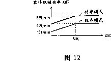
图12是示出将在图7的S9中执行的内容的图表;FIG. 12 is a diagram showing what will be executed in S9 of FIG. 7;
图13是示意性地示出作为能量限制程序的图7的S14的内容的流程图;FIG. 13 is a flowchart schematically showing the contents of S14 of FIG. 7 as an energy limiting program;
图14是示意性地示出图3的发电控制程序的内容的流程图;FIG. 14 is a flowchart schematically showing the contents of the power generation control program of FIG. 3;
图15是示出将由图14的S74到S77执行的内容的示例的图表;FIG. 15 is a diagram showing an example of content to be executed by S74 to S77 of FIG. 14;
图16是按时间顺序示出执行图3中所示的综合驱动控制程序和发电程序的结果的图表;FIG. 16 is a graph showing the results of executing the integrated drive control program and the power generation program shown in FIG. 3 in chronological order;
图17是示意性地示出本发明第二实施例所涉及的综合驱动控制系统中的主ECU18的计算机200所执行的能量限制程序的内容的流程图;FIG. 17 is a flowchart schematically showing the contents of an energy limiting program executed by the computer 200 of the
图18是示意性地示出本发明第三实施例所涉及的综合驱动控制系统中的主ECU18的计算机200所执行的能量限制程序的内容的流程图;FIG. 18 is a flowchart schematically showing the contents of an energy limiting program executed by the computer 200 of the
图19是示意性地示出将在图18中所示的能量限制程序中执行的内容的图表;Fig. 19 is a diagram schematically showing what will be executed in the energy limitation program shown in Fig. 18;
图20是示意性地示出将在图18中所示的能量限制程序中执行的内容的另一个图表;FIG. 20 is another diagram schematically illustrating what will be performed in the energy limitation program shown in FIG. 18;
图21是示意性地示出本发明第四实施例所涉及的综合驱动控制系统中的主ECU18的计算机200所执行的综合驱动控制程序的内容的流程图;以及21 is a flowchart schematically showing the contents of an integrated drive control program executed by the computer 200 of the
图22通过等式示意性地示出图21中所示的综合驱动控制程序所执行的内容。FIG. 22 schematically shows the contents executed by the integrated drive control program shown in FIG. 21 by equations.
具体实施方式Detailed ways
在下文中,将参照附图详细地描述本发明的一些具体实施例。Hereinafter, some specific embodiments of the present invention will be described in detail with reference to the accompanying drawings.
图1是本发明第一实施例所涉及的综合驱动控制系统的硬件结构的框图。所述综合驱动控制系统被安装在作为机器的机动车(在下文中也称之为车辆)上。所述车辆包括多个致动器(在图1中,表示为两个致动器)10、12,以及共用于这些致动器的能源14。FIG. 1 is a block diagram of a hardware configuration of an integrated drive control system according to a first embodiment of the present invention. The integrated drive control system is mounted on a motor vehicle (hereinafter also referred to as a vehicle) as a machine. The vehicle comprises a plurality of actuators (in FIG. 1 represented as two actuators) 10, 12, and an energy source 14 common to these actuators.
所述综合驱动控制系统包括检测驱动信息的驱动信息检测器16、主ECU(电子控制单元)18。此外,所述综合驱动控制系统对于每个致动器10、12来说包括独自ECU20、22、输入功率检测器24、26和输出功率检测器28、30。The integrated drive control system includes a drive information detector 16 that detects drive information, a main ECU (Electronic Control Unit) 18 . Furthermore, the integrated drive control system includes individual ECUs 20 , 22 , input power detectors 24 , 26 and output power detectors 28 , 30 for each actuator 10 , 12 .
驱动信息检测器16被设置成用于检测由车辆的驾驶员发出的用于驱动车辆的驾驶员指令、车辆的状态以及车辆所处的行驶环境。这里,作为示例,“驾驶员的指令”包括与车辆的加速相关的指令、与减速或制动作用中一个相关的指令、与转向等相关的指令。The driving information detector 16 is provided to detect a driver's instruction issued by the driver of the vehicle for driving the vehicle, the state of the vehicle, and the driving environment in which the vehicle is located. Here, as an example, the "driver's command" includes a command related to acceleration of the vehicle, a command related to one of deceleration or braking, a command related to steering, and the like.
主ECU18被设置成用于通过与多个致动器10、12中的相应一个相对应的多个独自ECU20、22作为整体管理多个致动器10、12。与之相反,独自ECU20、22被设置成用于基于来自于主ECU18的指令驱动相应的致动器10、12。The
输入功率检测器24、26被设置成用于检测输入到相应致动器10、12或输入到能源14的输入能量。具体地说,输入功率检测器24、26被设置成用于检测相应致动器10、12的电能消耗以及当相应致动器10、12用作电力发电机时用于检测致动器10、12所产生的电力。在任何情况中,都作为相应致动器10、12的电压和电流的乘积检测所述电能。The input power detectors 24 , 26 are arranged to detect input energy to the
输出功率检测器28、30被设置成用于检测分别从相应致动器10、12中输出的能量。具体地说,输出功率检测器28、30被设置成用于检测分别由相应致动器10、12的驱动而实际做的功的功率。The output power detectors 28, 30 are arranged to detect the energy output from the
所述能量被检测为作用在致动器10、12使之移动的物体上的力(或转矩)与物体的速度(或转数)的乘积。当所述物体本身为机动车时,所述能量被检测为通过将作用在车辆上的力和加速度与质量相乘所获得的数值与车辆速度(即,车辆的行驶速度)的乘积。The energy is detected as the product of the force (or torque) acting on the object being moved by the
图2示出功能框图中的综合驱动控制系统。从其功能的观点来看,综合驱动控制系统包括驱动要求确定单元40、综合能量管理单元42、以及驱动控制单元44。Figure 2 shows the integrated drive control system in a functional block diagram. From the viewpoint of its function, the integrated drive control system includes a drive
驱动要求确定单元40是用于将用于车辆的驱动要求确定成满足上述驾驶员的指令、车辆的状态和行驶环境的单元。作为示例,驱动要求包括,车辆的加速、减速、转弯量等。The driving
综合能量管理单元42为每个致动器计算满足上述驱动要求的期望功率DMP,并且基于所计算的DMP,确定将要供应给每个致动器10、12的电力以便获得期望的电力,作为要求电力REPsum。The integrated
综合能量管理单元42还计算为多个致动器10、12所确定的要求电力REP的总和作为总要求电力REPsum。The integrated
而且,综合能量管理单元42限制每个致动器10、12的期望功率DMP以使得所计算的REPsum不会超过车辆可用的电力。具体地说,为多个致动器10、12预先设定一个顺序,并且综合能量管理单元42基于所述顺序限制每个致动器10、12的期望功率DMP。Furthermore, the integrated
在本实施例中,车辆包括以下部件作为多个致动器10、12,如图3中所示的:In this embodiment, the vehicle includes the following components as a plurality of
(1)控制用于制动每个轮的摩擦制动器的制动器致动器50;(1) A
(2)控制用于使车辆转向的电动转向设备的转向致动器54;(2) controlling the
(3)驱动车辆的车辆电动机58;(3) The vehicle
(4)控制用以将车辆电动机58的驱动转矩传输到每个轮的电动CVT设备62的齿轮齿数比的CVT电动机66;(4)
(5)车辆的发光体70;以及(5) the
(6)用于车辆的空调器的空调器致动器74。(6) The
作为示例,制动器致动器50为用作制动器的驱动源的电动机、控制从压力源传输到致动器的压力的电磁阀等。As an example, the
在车辆加速时车辆电动机58用作车辆的电动电动机和动态功率源,并且在车辆减速时车辆电动机58用作电力发电机(再生电动机或制动电动机)。为了恢复车辆电动机所产生的电力和在车辆减速时通过能源14再生能量的程序,即,所谓的制动再生,车辆具有制动再生设备。因此,车辆电动机58不仅被看作是能量消耗单元而且还被看作是临时能量产生单元。The vehicle
空调器包括用于冷却车辆车厢的冷却器,并且其致动器为空调器致动器74。作为示例,空调器致动器74为驱动冷却器中的压缩机的电动机。The air conditioner includes a cooler for cooling the vehicle cabin, and its actuator is an
在本实施例中,为多个致动器设定顺序,以使得制动器致动器50、转向致动器54、车辆电动机58和CVT电动机66、发光体70和空调器致动器74基于该顺序被优先控制。In this embodiment, the sequence is set for the plurality of actuators so that the
因此,在本实施例中,当上述所计算的总要求电力REPsum超过容许功率AMP时,各个致动器的期望功率DMP将基于与上述优先权的顺序相反的顺序被限制,所述容许功率AMP为可通过车辆中的可用电力Epava实现的功率的最大值。Therefore, in the present embodiment, when the above-mentioned calculated total required power REPsum exceeds the allowable power AMP, the desired power DMP of each actuator will be limited based on the order reverse to the order of the above-mentioned priority, the allowable power AMP is the maximum value of power achievable with the available electric power Epava in the vehicle.
如从前面中可理解的,为所述多个致动器提供综合能量管理单元42以便进行能量管理,从而实现车辆中所限制的电力分布的最佳量或比率。As can be understood from the foregoing, an integrated
可通过用于使得电力分配最优化的目标函数给出车辆中的可用电力Epava与每个致动器的独自分配量Xi(i=1、2、3、......n)之间的关系,所述目标函数由以下等式表示:The difference between the available electric power Epava in the vehicle and the individual distribution amount Xi (i=1, 2, 3, . . . n) of each actuator can be given by an objective function for optimizing the electric power distribution , the objective function is expressed by the following equation:
Epava=∑XiEpava=∑Xi
由于电力的考虑因素与功率的考虑因素相同,因此所述目标函数也是表示与电力Epava相应的功率如何在各个致动器之中分配的方式的函数。Since the factors considered for electric power are the same as those for power, the objective function is also a function representing how the power corresponding to the electric power Epava is distributed among the respective actuators.
而且,可使用每个致动器的电力Epava的分配比率Ki,由以下等式表示每个独自分配量Xi:Also, using the distribution ratio Ki of the electric power Epava of each actuator, each individual distribution amount Xi can be expressed by the following equation:
Xi=Epava·KiXi=Epava·Ki
因此,通过综合能量管理单元42,从节约能量消耗的观点来看,每个致动器的分配因数Ki最优化,因此目标函数也是最优化的。Therefore, by the integrated
在前述描述中,已描述了驱动要求确定单元40和综合能量管理单元42。剩余的驱动控制单元44驱动每个致动器以使得可获得由综合能量管理单元42最终确定的期望功率DMP。驱动控制单元44监控每个致动器的实际功率MP,并且执行每个致动器的驱动的反馈控制。为了监控功率MP,使用上述功率检测器28、30。In the foregoing description, the driving
图3以框图的方式示出综合驱动控制系统的硬件结构的细节。FIG. 3 shows the details of the hardware structure of the integrated drive control system in a block diagram.
综合驱动控制系统包括,诸如所所述的驱动信息检测器16、检测驾驶员指令的驾驶员指令传感器90、检测车辆状态的车辆状态传感器92、以及检测与行驶环境相关的信息的行驶环境信息传感器94。The integrated drive control system includes, for example, the drive information detector 16 described above, the
驾驶员指令传感器90检测车辆转向系统(即,转向操作部件、制动操作部件以及加速器操作部件)的驾驶员的操作量作为驾驶员指令。The
车辆状态传感器92作为车辆状态检测车辆速度、轮速度、车辆驱动力、车辆加速、车辆减速、转向角、作用在每个轮的轮胎上的力或转矩等。The
行驶环境信息传感器94检测车辆本身与行驶在其前方的车辆之间的距离、车辆在其上行驶的道路的状态、车辆所行驶的地区的天气和温度等作为行驶环境信息。行驶环境信息传感器94可被设计成用于通过使用GPS或通过与道路信息中心的通讯而估计或预报车辆正在其上行驶或即将在其上行驶的道路环境。The running
在本实施例中,车辆包括用作能源14的燃料电池96(电力发电机)和独自电力源98。如从上述描述中可明白的,车辆电动机58还临时起到电力发电机的作用,因此可认为其构成能源14。In the present embodiment, the vehicle includes a fuel cell 96 (electric power generator) serving as the energy source 14 and a
燃料电池96从包含诸如氢等作为燃料的物质的燃料槽中取出燃料,并且使用所取出的燃料发电。燃料电池96由连接于主ECU18的燃料电池ECU100管理。燃料电池ECU100为独自ECU20、22的一个示例,并且这适用于由术语ECU表示的除主ECU18以外的其它系统元件。The
相反,电力源98被形成为储存由燃料电池96和稍后将描述的制动再生设备101所产生的电能的电池。电力源98可被形成得例如包括低压电池和高压电池。In contrast, the
与燃料电池96相似,电力源98也由连接于主ECU18的电力源ECU102管理。由电力检测器104检测从燃料电池96供应给电力源98的电力(所产生的电力),而由电力检测器106检测从制动再生设备101供应给电力源98的电力(所再生的电力)。电力检测器104和106都与主ECU18相连接,并且能够传送必要的信息。电力检测器104、106是输入功率检测器24、26的示例,并且它们也适用于稍后将描述的其它电力检测器。Similar to the
如上所述,车辆包括作为多个致动器的车辆电动机58、CVT电动机66、空调器致动器74、发光体70、制动器致动器50以及转向致动器54。As described above, the vehicle includes the
在该车辆中,通过制动器致动器50和作为电力发电机的车辆电动机的功能的共同操作实现制动作用。而且,在车辆中,当车辆电动机58用作电力发电机时,车辆电动机58所产生的电能被回收到电力源98。因此,上述制动再生设备101被设在该车辆上。In this vehicle, the braking action is achieved by the joint operation of the
制动再生设备101由连接于主ECU18以及连接于电力源ECU102的制动再生ECU110控制。由机械功率检测器112检测制动再生设备101上的实际载荷,即,功率。机械功率检测器112为输出功率检测器28、30的一个示例,并且它们也适用于稍后将描述的其它功率检测器。The
机械功率检测器112为每个轮将施加于其上的制动转矩和转动速度(轮速度)的乘积检测为功率。机械功率检测器112与制动再生ECU110以及主ECU18相连接。The
图4示意性地示出车辆的电能流。车辆包括作为用以产生电能的产生单元120的燃料电池96和制动再生设备101。而且,车辆包括作为用于储存电能的储存单元122的电力源98。此外,车辆包括作为用于消耗电能的消耗单元124的多个制动器。产生单元120所产生的电能被储存在储存单元122中同时所述电能被消耗单元124消耗。储存在储存单元122中的电力由消耗单元124消耗。通过该消耗可确保车辆的运动、安全和舒适。FIG. 4 schematically shows the electrical energy flow of a vehicle. The vehicle includes a
图5是横截面正视图,示意性地示出作为传输设备设在车辆上的电动CVT设备62的一个示例。电动CVT设备62是具有由皮带134围绕在其周围的一对带轮130、132的皮带&带轮类型的设备。车辆电动机58使得一个带轮130转动,并且该带轮130的转动通过皮带134被传输到另一个带轮132。带轮132的转动通过输出轴(未示出)被传输到车辆的驱动轮,因此车辆被驱动。FIG. 5 is a cross-sectional front view schematically showing one example of an
在电动CVT设备62中,带轮130的槽的两侧表面由彼此相对并且与带轮130同轴的一对转动体136、136构成。这也适用于另一个带轮132。In the
这对转动体136、136可沿与相应的带轮130、132同轴的方向相对于彼此位移。在电动CVT设备62中,通过CVT电动机66和转动传输机构140连续地改变这对转动体136、136之间的距离,从而连续地改变各个带轮130、132的槽的宽度。因此,围绕各个带轮130、132的皮带134的半径也被连续地改变,因此,车辆电动机58的转动速度的齿轮齿数比被连续地改变。The pair of
转动传输机构140包括作为分配机构的示例的齿轮系142,所述分配机构将共用于这对带轮130、132的CVT电动机66的转动分配给每个带轮130、132,作为与之同轴的转动。此外,对于每个带轮130、132来说,转动传输机构140包括球弹簧144,所述球弹簧144作为用于将通过齿轮系142分配到每个带轮130、132的转动转化为沿这对转动体136、136的轴向的相对线性移动的机构的一个示例。The
因此,在电动CVT设备62中,基于CVT电动机66的转动角确定车辆电动机58的转动速度的齿轮齿数比。通过转动角传感器146检测CVT电动机66的转动角。Therefore, in the
如图3所示,当从电力源98中供应的电能被消耗时,车辆电动机58被驱动。车辆电动机58由连接于主ECU18以及连接于电力源ECU102的车辆电动机ECU150控制。由连接于主ECU18、车辆电动机ECU150和电力源ECU102的电力检测器152检测车辆电动机58所消耗的电力。As shown in FIG. 3 , the
此外,由连接于主ECU18和车辆电动机ECU150的机械功率检测器154检测车辆电动机58的实际功率。作为示例,机械功率检测器154将每个驱动轮的功率检测为施加在轮上的驱动转矩与轮的转动速度的乘积。Further, the actual power of the
当从电力源98中供应的电能被消耗时,CVT电动机66也被驱动。CVT电动机66由连接于主ECU18、电力源ECU102以及车辆电动机ECU150的变速器ECU160控制。由连接于主ECU18、变速器ECU160和电力源ECU102的电力检测器162检测CVT电动机66所消耗的电力。When the electric power supplied from the
当从电力源98中供应的电能被消耗时,空调器致动器74也被驱动。空调器致动器74由连接于主ECU18的空调器ECU166控制。由连接于主ECU18和空调器ECU166的电力检测器168检测空调器致动器74所消耗的电力。When the electric power supplied from the
另外,由连接于空调器ECU166和主ECU18的机械功率检测器170检测空调器致动器74的实际功率。作为示例,机械功率检测器170将所述功率检测为气流与车辆的室温的乘积。In addition, the actual power of the
当从电力源98中供应的电能被消耗时,制动器致动器50也被驱动。制动器致动器50由连接于主ECU18的制动器ECU174控制。由连接于主ECU18和制动器ECU174的电力检测器176检测制动器致动器50所消耗的电力。When the electric power supplied from the
此外,由连接于制动器ECU174和主ECU18的机械功率检测器178检测制动器致动器50的实际功率。作为示例,机械功率检测器178将每个驱动轮的功率检测为轮的制动转矩与轮的转动速度的乘积。Furthermore, the actual power of the
当从电力源98中供应的电能被消耗时,转向致动器54被驱动。转向致动器54由连接于主ECU18的转向ECU182控制。由连接于主ECU18和转向ECU182的电力检测器184检测转向致动器54所消耗的电力。The steering
此外,由连接于转向ECU182和主ECU18的机械功率检测器186检测转向致动器54的实际功率。In addition, the actual power of the
当从电力源98中供应的电能被消耗时,发光体70被驱动。发光体70由连接于主ECU18的发光体ECU190控制。由连接于主ECU18和发光体ECU190的电力检测器192检测发光体70所消耗的电力。When the power supplied from the
此外,由连接于发光体ECU190和主ECU18的机械功率检测器194检测发光体70的实际功率。In addition, the actual power of the
图6是示意性地示出主ECU18的结构的框图。主ECU18主要包括计算机200。如人所共知的,计算机200由通过总线208相互连接的CPU202(处理器的一个示例)、ROM204(存储器的一个示例)和RAM204(存储器的另一个示例)构成。包括综合驱动控制程序和发电控制程序的各种程序被预先储存在ROM204中。FIG. 6 is a block diagram schematically showing the configuration of
图7以流程图的形式示出综合驱动控制程序的内容。在计算机200处于运行状态时重复地执行综合驱动控制程序。FIG. 7 shows the contents of the integrated drive control program in the form of a flowchart. The integrated drive control program is repeatedly executed while the computer 200 is in the running state.
每次执行综合驱动控制程序时,首先,在步骤S1(在下文中简称之为S1,对于其它步骤也是如此),由驾驶员指令传感器90检测驾驶员的指令。接着,在S2中,由车辆状态传感器92检测车辆的状态。之后,在S3中,由行驶环境信息传感器94检测行驶环境信息。Every time the integrated drive control routine is executed, first, at step S1 (hereinafter simply referred to as S1, the same applies to other steps), the driver's command is detected by the driver's
之后在S4中,基于所检测的驾驶员指令、车辆状态和行驶环境信息发出用于车辆的驱动要求。所述驱动要求包括基于驾驶员指令驱动车辆的要求和与驾驶员指令无关地自动驱动车辆以提高车辆的安全性的要求。后一种要求的一个示例为,考虑到本车辆的当前速度,当本车辆和行驶在前方的车辆之间的距离不足时,自动地煞住车辆的自动制动作用。Then in S4, a drive request for the vehicle is issued based on the detected driver's command, vehicle state, and running environment information. The driving request includes a request to drive the vehicle based on a driver's instruction and a request to automatically drive the vehicle regardless of the driver's instruction to improve the safety of the vehicle. An example of the latter requirement is an automatic braking action that automatically engages the vehicle when the distance between the host vehicle and a vehicle driving ahead is insufficient, taking into account the current speed of the host vehicle.
接下来,在S5中,将经济模式或功率模式转动一种选择为用以控制致动器的控制模式。可基于驾驶员的决定作出所述选择或者可自动作出选择。Next, in S5, one of the selections of the economy mode or the power mode is turned as the control mode for controlling the actuator. The selection may be made based on a driver's decision or may be made automatically.
这里,“经济模式”是这样一种控制模式,其中由所述致动器消耗的能量的节约比致动器的驱动要求的实现具有更高的优先权。相反,“功率模式”是这样一种控制模式,其中致动器的驱动要求的实现比由所述致动器消耗的能量的节约具有更高的优先权。Here, the "economy mode" is a control mode in which the saving of energy consumed by the actuator has a higher priority than the fulfillment of the drive demand of the actuator. In contrast, a "power mode" is a control mode in which the fulfillment of the drive requirements of the actuators has a higher priority than the saving of the energy consumed by said actuators.
当选择了控制模式时,作为示例,基于驾驶员的指令(例如,驾驶员所作出的驱动操作部件的操作速度或操作量)或基于行驶环境信息(例如,跟随距离)确定目前车辆是处于正常操作状态还是处于紧急操作状态。当确定车辆处于正常状态时,选择经济模式,而当确定车辆处于紧急状态时,选择功率模式。When the control mode is selected, as an example, it is determined based on the driver's instruction (for example, the operation speed or operation amount of the driving operation member made by the driver) or based on the running environment information (for example, the following distance) to determine whether the current vehicle is in the normal state. The operating state is still in the emergency operating state. When it is determined that the vehicle is in a normal state, the economy mode is selected, and when it is determined that the vehicle is in an emergency state, the power mode is selected.
之后,在S6中,将实现所确定的驱动要求所需的每个致动器的功率MP计算为期望功率DMP。After that, in S6, the power MP of each actuator required to realize the determined driving demand is calculated as the desired power DMP.
作为示例,当所确定的驱动要求为:重量为1t的车辆在约0.2G的加速度下被加速以使得车辆速度在0.25min内从0km/h增加到100km/h时,车辆电动机58的期望功率DMPmtr被计算为大约54kW,即,驱动力F(=车辆重量和加速度的乘积)与车辆速度V的乘积。As an example, when the determined drive requirement is that a vehicle with a weight of 1t is accelerated at an acceleration of about 0.2G so that the vehicle speed increases from 0km/h to 100km/h within 0.25min, the desired power DMPmtr of the
当所确定的驱动要求为:重量为1t的车辆应克服约0.05G的惯性减速度在100km/h的车辆速度下稳定行驶时,车辆电动机58的期望功率DMPmtr被计算为大约14kW。When the determined driving requirement is that a vehicle weighing 1 ton should overcome an inertial deceleration of about 0.05 G and run stably at a vehicle speed of 100 km/h, the desired power DMPmtr of the
应该注意的是,在电动机中,通常,功率MP被计算为转矩T和转数N的乘积,而电力EP被计算为供应给电动机的电压E与流过电动机的电流I的乘积。当电动机上的能量损耗可忽略不计时,功率MP和电力EP彼此相等。It should be noted that in electric motors, generally, power MP is calculated as the product of torque T and number of revolutions N, and electric power EP is calculated as the product of voltage E supplied to the motor and current I flowing through the motor. When the energy loss on the motor is negligible, the power MP and the electric power EP are equal to each other.
之后,在S7中,实现所计算的期望功率DMP所需的每个致动器的电力EP被计算为要求电力REP。在以下描述中,将采用车辆电动机58作为致动器的示例具体进行描述。After that, in S7, electric power EP of each actuator required to realize the calculated desired power DMP is calculated as required electric power REP. In the following description, an example using the vehicle
如图8所示,对于通用电动机来说,当电动机电压E保持恒定而电动机电流I改变时,在图表中由从左至右向下倾斜的多条直线表示的关系保持在电动机转矩T和电动机的转数N之间。这是通用电动机特征。As shown in Fig. 8, for a universal motor, when the motor voltage E is kept constant and the motor current I is changed, the relationship represented by the multiple straight lines sloping downward from left to right in the graph remains between the motor torque T and Between the number of revolutions of the motor N. This is a general motor characteristic.
在所述多条直线中,最大输出点位于图表的最上面的直线上。最大输出点表示电动机转矩T和电动机的转数N的乘积最大的点,因此,它表示功率MP的最大值。Among the plurality of straight lines, the maximum output point is located on the uppermost straight line of the graph. The maximum output point indicates the point at which the product of the motor torque T and the number of revolutions N of the motor is the largest, and therefore, it indicates the maximum value of the power MP.
当必须以最大功率驱动电动机时,可根据图8的图表所表示的电动机特征确定目标电动机转矩T*和电动机的目标转数N*。When it is necessary to drive the motor with maximum power, the target motor torque T * and the target number of revolutions N * of the motor can be determined from the motor characteristics represented by the graph of FIG. 8 .
然而,如图8所示,对于通用电动机来说,最大输出点与电动机的最大效率点不同,并且该点在图表的最上面的直线上从最大输出点位移到具有较小电动机转矩T和电动机的较大转数N的一侧。However, as shown in Fig. 8, for a universal motor, the point of maximum output is different from the point of maximum efficiency of the motor, and the point is shifted on the uppermost straight line of the graph from the point of maximum output to have a smaller motor torque T and The side with the larger number of revolutions N of the motor.
因此,当处于固定状态中的车辆电动机58被通电以便具有电动机转矩T和电动机转数N的交点,即,表示功率的点从0移动到最大输出点时,考虑到能量节约,更适宜的是,使得表示功率的点通过最短路径移动到最大效率点,之后使得电动机电流I增加同时保持电动机电压E恒定,从而使得表示功率的点从最大效率点移动到最大输出点,而不是使得表示功率的点沿最短路径移动。Therefore, when the
图9是一个图表,示出当电动机电流I和电动机电压E的交点,即,表示电力P的点从0通过最大效率点移动到最大输出点时,以适当的梯度增加的电动机电流I和电动机电压E。FIG. 9 is a graph showing the motor current I and the motor current I increasing with appropriate gradients when the intersection point of the motor current I and the motor voltage E, that is, the point representing the power P, moves from 0 through the point of maximum efficiency to the point of maximum output. Voltage E.
更具体地说,首先,电动机电流I和电动机电压E一起随时间成比例地增加。通过该增加,表示电力的点达到最大效率点。之后,电动机电流I随时间成比例地增加而电动机电压E保持恒定。More specifically, first, the motor current I and the motor voltage E increase proportionally with time together. Through this increase, the point representing power reaches the point of maximum efficiency. Thereafter, the motor current I increases proportionally with time while the motor voltage E remains constant.
图9的图表示出电动机电流I和电动机电压E的时间转变(随时间的变化),因此,利用该图表,可预先将电力EP计算为每个时点的电动机电流I和电动机电压E的乘积。The graph of FIG. 9 shows the time transition (change with time) of the motor current I and the motor voltage E, and therefore, using this graph, the electric power EP can be calculated in advance as the product of the motor current I and the motor voltage E at each time point .
然而,应该注意的是,图9的图表示出当车辆电动机58的期望功率DMP与图8的最大输出点所表示的功率(即,最大功率)相同时的电动机电流I和电动机电压E之间的关系。However, it should be noted that the graph of FIG. 9 shows the relationship between the motor current I and the motor voltage E when the desired power DMP of the
与之相反,在图8的图表中,当车辆电动机58的期望功率DMP小于上述最大功率时,电动机电流I和电动机电压E将随着时间改变,以使得当电动机转矩T和电动机转数N的乘积与期望功率相配时,电动机转矩T和电动机转数N的交点为最终目标。In contrast, in the graph of FIG. 8, when the desired power DMP of the
在图8的图表中,当达到最终目标时,可确定出最终目标下的电动机电压E。因此,从所确定的电动机电压E和图9的图表中可发现最终目标下的电动机电流I。In the graph of FIG. 8 , the motor voltage E at the final target can be determined when the final target is reached. Thus, from the determined motor voltage E and the graph of FIG. 9 the motor current I at the final target can be found.
因此,甚至当车辆电动机58的期望功率DMP小于上述最大功率时,也可分别计算电动机电流I和电动机电压E的时间转变。因此,也可计算目标电动机转矩T*和电动机的目标转数N*的时间转变。Therefore, even when the desired power DMP of the vehicle
在上述描述中,已经描述了用以加速车辆的车辆电动机58的控制。在下文中,将描述用以减速车辆的车辆电动机58的控制。In the above description, the control of the vehicle
当车辆被减速时,车辆电动机58用作电力发电机(再生电动机或制动电动机),并且使用发电阻力使得车辆被减速。然而,应该注意的是,可能不仅仅通过车辆电动机58实现目标车辆速度和目标减速。在这种情况下,需要制动器的辅助。When the vehicle is decelerated, the
图10是通过曲线示意性地示出当车辆电动机58发电时再生电动机转矩T和电动机转数N之间所保持的关系的图表。在图表的曲线上,具有用作再生电动机的车辆电动机58的最大输出点,以及最大发电效率点,在该点下车辆电动机58的发电效率最高。FIG. 10 is a graph schematically showing by a graph the relationship maintained between the regenerative motor torque T and the motor rotation number N when the vehicle
因此,当车辆被减速时,根据图10的图表中的曲线所表示的特征,适合于实现由驱动要求指示的期望功率DMP的再生电动机转矩T和电动机转数N的组合可被确定为目标电动机转矩T*和电动机的目标转数N*的组合。Therefore, when the vehicle is decelerated, the combination of the regenerative motor torque T and the motor revolution number N suitable for realizing the desired power DMP indicated by the drive request can be determined as the target according to the characteristics represented by the curves in the graph of FIG. 10 A combination of the motor torque T * and the target number of revolutions N * of the motor.
之后,以与用于加速相似的方式计算用于车辆的减速所需的车辆电动机58的要求电力REP。After that, the required electric power REP of the vehicle
当驱动要求与车辆的加速或减速相关时车辆电动机58被驱动。在这种情况下,除车辆电动机58的控制之外,还需要CVT电动机66或制动器致动器50的控制。在下文中将具体进行描述。The vehicle
当车辆被加速时,通过车辆电动机58和电动CVT设备62的组合确定车辆速度和车身驱动力。因此,从电动机的所述确定的目标转数N*和驱动要求所指示的目标速度的关系中,可确定电动CVT设备62的齿轮齿数比γ。或者,可从所述确定的目标电动机转矩T*和驱动要求所指示的车身驱动力之间的关系中,确定电动CVT设备62的齿轮齿数比γ。When the vehicle is accelerated, the vehicle speed and vehicle body driving force are determined by the combination of the vehicle
同样地,当车辆被减速时,通过车辆电动机58和电动CVT设备62的组合确定车辆速度和车身驱动力。因此,从电动机的所述确定的目标转数N*和驱动要求所指示的目标速度的关系中,可确定电动CVT设备62的齿轮齿数比γ。或者,可从所述确定的目标电动机转矩T*和驱动要求所指示的车身驱动力之间的关系中,确定电动CVT设备62的齿轮齿数比γ。Likewise, when the vehicle is decelerated, the vehicle speed and vehicle body driving force are determined by the combination of the vehicle
图11是表示齿轮齿数比γ与CVT电动机66的转动角θ之间的示范性关系的图表。CVT电动机66基于该图表中所示的特征被驱动。在S8中,也计算出CVT电动机66的要求电力REP。FIG. 11 is a graph showing an exemplary relationship between the gear ratio γ and the rotation angle θ of the
在前面的描述中,已在将用于车辆电动机58的要求电力REP的计算取作示例的情况下描述了S7中所要执行的内容。最后,通过S7的执行,计算用于制动器致动器50的要求电力REPbrk、用于转向致动器54的要求电力REPstr、用于驱动车辆电动机58的要求电力REPmtr(即,用于车辆电动机58的要求电力与用于CVT的要求电力的总和)、用于发光体70的要求电力REPlig以及用于空调器致动器74的要求电力REPa/c并且将它们储存在RAM206中。In the foregoing description, what is to be executed in S7 has been described taking the calculation of the required electric power REP for the vehicle
之后,在图7的S8中,将用于所有致动器的要求电力REP的总和计算为狭义的总要求电力REPsum。在本实施例中,通过从狭义计算的总要求电力REPsum中减去燃料电池96所产生的电力和制动再生设备101所产生的电力计算出表观总要求电力REPsum(在下文中简称之为“总要求电力REPsum”)。After that, in S8 of FIG. 7 , the sum of the required power REP for all the actuators is calculated as the narrowly defined total required power REPsum. In this embodiment, the apparent total required power REPsum (hereinafter simply referred to as " Total Power Requirements REPsum").
之后,在S9中,计算电力源98的电荷状态SOC,即,电力源98的剩余容量。这里,“电荷状态SOC”是表示电力源98中的剩余电力的物理值,通过用全充电状态作为参考的百分数表示。After that, in S9 , the state of charge SOC of the
为了计算电荷状态SOC,作为示例,随着时间的过去,连续地测量和累积电力源98的电压和从电力源98中取出的电流,从而估计出消耗的电力(泻出的电力)。使用所估计的电力消耗,可计算出每一时点下的电荷状态SOC。当结合考虑电力源98的温度和电力源98的退化校正所估计的电力消耗时,可以更高的精确性估计出电荷状态SOC。To calculate the state of charge SOC, as an example, the voltage of the
在S9中,基于以这种方式计算的电荷SOC的状态和上述选择的控制模式,确定容许功率AMP。所确定的容许功率AMP被储存在ROM206中。In S9, based on the state of charge SOC calculated in this way and the above-mentioned selected control mode, allowable power AMP is determined. The determined allowable power AMP is stored in ROM 206 .
这里,“容许功率AMP”表示电荷状态SOC的每分钟容许消耗的比率。电荷状态SOC的单位为百分数,因此,容许功率AMP的单位为percent/min。Here, "allowable power AMP" indicates a rate of allowable consumption per minute of the state of charge SOC. The unit of charge state SOC is percentage, therefore, the unit of allowable power AMP is percent/min.
这里,电荷状态SOC用于比率表示为剩余在电力源98中的电力,因此,它具有相同量度。因此,容许功率AMP具有来自于电力与时间的商,因此,可认为其与电力具有相同的量度。Here, the state of charge SOC is used for the ratio expressed as the power remaining in the
图12是一图表,示出容许功率AMP如何与电荷状态SOC一起改变,以及在功率模式和经济模式中它们之间的关系不同。在电荷状态SOC不高于50%的区域中,容许功率AMP与电荷状态SOC一起增加,并且当SOC超过50%时,在功率模式和经济模式两者中,容许功率AMP保持恒定。然而,应该注意的是,在电荷状态SOC的整个区域中,功率模式中的容许功率AMP都大于经济模式。FIG. 12 is a graph showing how the allowable power AMP changes together with the state of charge SOC, and their relationship is different in the power mode and the economy mode. In a region where the state of charge SOC is not higher than 50%, the allowable power AMP increases together with the state of charge SOC, and when the SOC exceeds 50%, the allowable power AMP remains constant in both the power mode and the economy mode. However, it should be noted that the allowable power AMP in the power mode is larger than the economy mode in the entire region of the state of charge SOC.
之后,在图7的S10中,确定S8中所计算的总要求电力REPsum是否超过S9中所确定的容许功率AMP。如果认为总要求电力REPsum没有超过容许功率AMP,所述确定结果为否,因此,流程前进到S11。After that, in S10 of FIG. 7 , it is determined whether the total required power REPsum calculated in S8 exceeds the allowable power AMP determined in S9 . If it is considered that the total required power REPsum does not exceed the allowable power AMP, the result of the determination is NO, and therefore, the flow proceeds to S11.
在S11中,将要供给到每个致动器的电力EP被确定为供应电力SEP。具体地说,将其确定为等于步骤S7中所计算的用于每个致动器的要求电力REP。之后,在S12中,基于所确定的供应电力SEP,确定将要施加到每个致动器的电压和将要施加到每个致动器的电流,因此,确定到每个致动器的输出。In S11, electric power EP to be supplied to each actuator is determined as supply electric power SEP. Specifically, it is determined to be equal to the required electric power REP for each actuator calculated in step S7. After that, in S12, based on the determined supply power SEP, the voltage to be applied to each actuator and the current to be applied to each actuator are determined, and thus, the output to each actuator is determined.
接着,在S13中,每个致动器都由所确定的电压和电流驱动。参考由相应的功率检测器检测的实际功率对每个致动器的驱动进行反馈控制。Next, in S13, each actuator is driven by the determined voltage and current. The drive of each actuator is feedback-controlled with reference to the actual power detected by the corresponding power detector.
通过这些步骤,完成了综合驱动控制程序的一个执行步骤。Through these steps, one execution step of the integrated drive control program is completed.
已经描述了其中总要求电力REPsum不超过容许功率AMP的一个示例。当总要求电力REPsum超过容许功率AMP时,S10的确定结果为是,因此,流程前进到S14。An example in which the total required power REPsum does not exceed the allowable power AMP has been described. When the total required power REPsum exceeds the allowable power AMP, the determination result of S10 is Yes, and therefore, the flow advances to S14.
图13是流程图,示意性地示出作为功率限制程序的S14的细节。FIG. 13 is a flowchart schematically showing details of S14 as a power limiting procedure.
在功率限制程序中,首先,在S31中,从RAM中读取容许功率AMP,并且在S32中,将可从电力源98中供应的可用电力Epava设定为等于所读取的容许功率AMP的数值。In the power limit program, first, in S31, the allowable power AMP is read from the RAM, and in S32, the available electric power Epava that can be supplied from the
之后,在S33中,用于制动器致动器50的要求电力REPbrk依原样被设定为用于制动器致动器50的供应电力SEPbrk,并且从可用电力Epava中减去供应电力SEPbrk,从而更新可用电力Epava。After that, in S33, the required power REPbrk for the
之后,在S34中,确定为转向致动器54计算的要求电力REPstr是否等于或小于当前的可用电力Epava。After that, in S34, it is determined whether the required electric power REPstr calculated for the
当要求电力REPstr等于或小于可用电力Epava时,S34的确定结果为是,从而在S35中,要求电力REPstr依原样被设定为用于转向致动器54的供应电力SEPstr,并且从可用电力Epava的当前值中减去供应电力SEPstr,从而更新可用电力Epava。When the required power REPstr is equal to or smaller than the available power Epava, the determination result of S34 is Yes, so that in S35, the required power REPstr is set as the supply power SEPstr for the
与之相反,当要求电力REPstr大于可用电力Epava的当前值时,S34的确定结果为否,并且在S36中,可用电力Epava依原样被设定为用于转向致动器54的供应电力SEPstr,并且可用电力Epava被更新为0。之后马上终止功率限制程序的一个执行步骤。In contrast, when the required power REPstr is larger than the current value of the available power Epava, the determination result of S34 is NO, and in S36 the available power Epava is set as the supply power SEPstr for the
之后,在S37中,确定为发光体70所计算的要求电力REPlig是否等于或小于可用电力EVava的当前值。After that, in S37, it is determined whether the required electric power REPlig calculated for the
当要求电力REPlig等于或小于可用电力Epava的当前值时,S37的确定结果为是,并且在S38中,要求电力REPlig依原样被设定为用于发光体70的供应电力SEPlig,并且从可用电力Epava的当前值中减去供应电力SEPlig,从而更新可用电力Epava。When the required power REPlig is equal to or less than the current value of the available power Epava, the determination result of S37 is Yes, and in S38, the required power REPlig is set as the supply power SEPlig for the
与之相反,当要求电力REPlig大于可用电力Epava的当前值时,S37的确定结果为否,并且在S39中,可用电力Epava依原样被设定为用于发光体70的供应电力SEPlig,并且可用电力Epava被更新为0。之后马上终止功率限制程序的一个执行步骤。On the contrary, when the required power REPlig is larger than the current value of the available power Epava, the determination result of S37 is NO, and in S39, the available power Epava is set as the supply power SEPlig for the
之后,在S40到S42中,确定用于车辆电动机58的供应电力SEPmtr。After that, in S40 to S42, the supply electric power SEPmtr for the vehicle
在车辆电动机58进行的车辆加速期间制动器的操作可能变得必要。当在没有考虑这样一种可能性的情况下确定出可由车辆电动机58消耗的电能量时,在需要时实际制动器的操作将困难。Operation of the brakes may become necessary during vehicle acceleration by the vehicle
反之,当车辆速度较高并且车辆电动机58的转数较高时,当制动器被操纵时发生车辆电动机58所进行的再生制动作用,因此,电力源98被充电。当车辆速度较高时充电的效果较高。Conversely, when the vehicle speed is high and the number of revolutions of the vehicle
因此,在S40中,为了确保准备用于制动器潜在操作的电能,从可用电力Epava的当前值中减去为制动器潜在操作所储备的储备电力PEP,这样,为车辆电动机58计算出减弱的电力LEP。储备电力PEP被定义为随着车辆速度增加而减小的车辆的函数。Therefore, in S40, in order to ensure the electric energy prepared for the potential operation of the brakes, the reserve electric power PEP reserved for the potential operation of the brakes is subtracted from the current value of the available electric power Epava, thus, the weakened electric power LEP is calculated for the vehicle
此外,在S40中,确定为车辆电动机58所计算的要求电力REPmtr是否等于或小于所计算的减弱电力LEP。Further, in S40, it is determined whether the calculated required electric power REPmtr for the vehicle
当要求电力REPmtr等于或小于减弱电力LEP时,S40的确定结果为是,并且在S41中,要求电力REPmtr依原样被设定为用于车辆电动机58的供应电力SEPmtr,并且从可用电力Epava中减去供应电力SEPmtr,从而更新可用电力Epava。When the required power REPmtr is equal to or smaller than the weakened power LEP, the determination result of S40 is Yes, and in S41, the required power REPmtr is set as the supply power SEPmtr for the
与之相反,当要求电力REPmtr大于减弱电力LEP时,S40的确定结果为否,并且在S42中,可用电力Epava依原样被设定为用于车辆电动机58的供应电力SEPmtr,并且可用电力Epava被更新为0。之后马上终止功率限制程序的一个执行步骤。In contrast, when the required power REPmtr is larger than the weakened power LEP, the determination result of S40 is NO, and in S42, the available power Epava is set as the supply power SEPmtr for the
之后,在S43中,确定用于空调器致动器74的要求电力REPa/c是否等于或小于可用电力EVava的当前值。After that, in S43, it is determined whether the required electric power REPa/c for the
当要求电力REPa/c等于或小于可用电力Epava的当前值时,S43的确定结果为是,并且在S44中,要求电力REPa/c依原样被设定为用于空调器致动器74的供应电力SEPa/c,并且从可用电力Epava的当前值中减去供应电力SEPa/c,从而更新可用电力Epava。When the required power REPa/c is equal to or smaller than the current value of the available power Epava, the determination result of S43 is Yes, and in S44, the required power REPa/c is set as it is for the supply of the
与之相反,当要求电力REPa/c大于可用电力Epava的当前值时,S43的确定结果为否,并且在S45中,可用电力Epava依原样被设定为用于空调器致动器74的供应电力SEPa/c,并且可用电力Epava被更新为0。In contrast, when the required power REPa/c is larger than the current value of the available power Epava, the determination result of S43 is NO, and in S45, the available power Epava is set as it is for the supply of the
在任何情况下,这里都终止功率限制程序的一个执行步骤。In any case, an execution step of the power limiting procedure is terminated here.
图14是流程图,示意性地示出发电控制程序的内容。与综合驱动控制程序相似,在计算机200处于运行状态也重复地执行发电控制程序。Fig. 14 is a flowchart schematically showing the contents of the power generation control program. Similar to the integrated drive control program, the power generation control program is also repeatedly executed while the computer 200 is running.
每次执行发电控制程序时,首先,在S71中,使用电力检测器152、162、168、176、184和192将每单位时间电力源98处消耗的电流量检测为消耗电流CC。接下来,在S72中,使用电力检测器104和106,将每单位时间电力源98所恢复(充电)的电流量检测为恢复电流RC。Every time the power generation control program is executed, first, in S71 , the amount of current consumed at the
之后,在S73中,电荷状态SOC的当前值SOC(n)被计算为当前SOC转换系数K与从恢复电流RC的检测值中减去检测的消耗电流CC所获得的数值的乘积与电荷状态SOC的最终值SOC(n-1)的总和。所计算的当前值SOC(n)作为最后的电荷状态SOC被储存在ROM204的非易失性存储部分中。After that, in S73, the current value SOC(n) of the state of charge SOC is calculated as the product of the current SOC conversion coefficient K and a value obtained by subtracting the detected consumption current CC from the detected value of the recovery current RC and the state of charge SOC The sum of the final values of SOC(n-1). The calculated current value SOC(n) is stored in the nonvolatile storage portion of the ROM 204 as the last state of charge SOC.
之后,在S74中,确定所计算的当前值SOC(n)是否大于阈值α1。当所计算的当前值SOC(n)大于阈值α1时,确定结果为是,并且在S76中,确定当前值SOC(n)是否大于阈值α2(阈值α2大于阈值α1)。当当前值SOC(n)大于阈值α2时,确定结果为是,并且在S77中,停止燃料电池96的发电。After that, in S74, it is determined whether the calculated current value SOC(n) is larger than the threshold value α1. When the calculated current value SOC(n) is larger than the threshold value α1, the determination result is Yes, and in S76, it is determined whether the current value SOC(n) is larger than the threshold value α2 (threshold value α2 is larger than the threshold value α1). When the current value SOC(n) is larger than the threshold value α2, the determination result is Yes, and in S77, the power generation of the
与之相反,当当前值SOC(n)不大于阈值α1时,S74的确定结果为否,并且在S75中执行燃料电池96的发电。当当前值SOC(n)大于阈值α1但不大于阈值α2时,S74的确定结果为是并且S76的确定结果为否,并且跳过步骤S75和S77。因此,燃料电池96的发电被保持在与以前相同的状态下。In contrast, when the current value SOC(n) is not greater than the threshold value α1, the determination result of S74 is NO, and power generation by the
这样,终止了发电控制程序的一个执行步骤。Thus, one execution step of the power generation control program is terminated.
另外,应该注意的是,上述阈值α1和α2可都被设定为规定值或可变值。在后一种情况下,可基于当车辆速度较慢时通过再生恢复到电力源98的期望电流量变得更小这样的事实,将每个阈值α1和α2设定为随着消耗电流CC增加而变得更小的可变值,或者将其设定为随着车辆速度减小而变得更小的可变值。In addition, it should be noted that the above thresholds α1 and α2 may both be set as prescribed values or as variable values. In the latter case, each of the thresholds α1 and α2 may be set to increase as the consumption current CC increases based on the fact that the desired amount of current recovered to the
图15是图表,示意性地示出如上所述当每个阈值α1和α2被设定为可变值时保持在每个电荷状态SOC、消耗电流CC、车辆速度V和发电的存在/不存在的关系。15 is a graph schematically showing the presence/absence of each state of charge SOC, consumption current CC, vehicle speed V, and power generation maintained when each threshold value α1 and α2 is set to a variable value as described above Relationship.
这里,如从图表中明白的,当电荷状态SOC相同时,当消耗电流CC变得更大时发电的执行更有可能,并且当车辆速度更小时发电的执行更有可能。Here, as is clear from the graph, when the states of charge SOC are the same, execution of electric power generation is more likely when the consumption current CC becomes larger, and execution of electric power generation is more likely when the vehicle speed is smaller.
当消耗电流CC相同时,当电荷状态SOC变得更小时发电的执行更有可能,并且当车辆速度更小时发电的执行更有可能。When the consumption current CC is the same, execution of electric power generation is more likely as the state of charge SOC becomes smaller, and execution of electric power generation is more likely as the vehicle speed is smaller.
图16在相同的图表中示出,当在相对于车辆速度V、温度T和电荷状态SOC的特定条件下执行综合驱动控制程序和发电控制程序时,由车辆电动机58和空调器致动器74的消耗电力、容许功率AMP以及总要求电力REPsum如何随着时间变化的示范性方式。FIG. 16 shows in the same graph, when the integrated drive control program and the power generation control program are executed under certain conditions with respect to the vehicle speed V, temperature T, and state of charge SOC, by the
特定条件如下所述。Specific conditions are described below.
(1)与车辆速度V相关的条件(1) Conditions related to vehicle speed V
a.停留周期(期间)a. Stay period (period)
基于驾驶员指令,在车辆的行驶开关接通之后两分钟,车辆保持在静止状态。Based on the driver's command, the vehicle remains in a stationary state for two minutes after the vehicle's travel switch is turned on.
b.加速周期b. Acceleration cycle
之后,车辆被加速以使得车辆速度在约0.2G的加速度下在0.25min内从0km/h增加到100km/h。Afterwards, the vehicle is accelerated such that the vehicle speed increases from 0 km/h to 100 km/h within 0.25 min at an acceleration of about 0.2 G.
c.稳定行驶周期c. Stable driving cycle
在加速结束之后,车辆保持稳定行驶,以保持100km/h的车辆速度。After the end of the acceleration, the vehicle keeps driving steadily to maintain the vehicle speed of 100 km/h.
d.减速周期d. Deceleration period
在稳定行驶周期结束之后,车辆被减速以使得车辆速度在约0.2G的加速度下在0.25min内从100km/h减小到0km/h。After the steady driving period ended, the vehicle was decelerated so that the vehicle speed decreased from 100 km/h to 0 km/h within 0.25 min under an acceleration of about 0.2 G.
(2)与温度T相关的条件(2) Conditions related to temperature T
a.大气温度为35℃。a. Atmospheric temperature is 35°C.
b.在初始状态下车辆的车厢温度为50℃,并且在接通车辆的行驶开关的同时,设定25℃的目标温度。b. In the initial state, the cabin temperature of the vehicle is 50° C., and a target temperature of 25° C. is set while the running switch of the vehicle is turned on.
(3)与电荷状态SOC相关的条件(3) Conditions related to the state of charge SOC
a.初始值a. Initial value
电荷状态SOC的初始值为70%。The initial value of the state of charge SOC is 70%.
b.电荷状态SOC的减小量(减小梯度)b. The amount of reduction in the state of charge SOC (decrease gradient)
-在加速周期中,电荷状态SOC每分钟减小40%。- During the acceleration cycle, the state of charge SOC decreases by 40% per minute.
-在稳定行驶周期中,电荷状态SOC每分钟减小5%。- The state of charge SOC decreases by 5% per minute during the steady driving cycle.
-在空调器处于运转中时,在用以获得目标车厢温度的运转的转变态(其中车厢温度每分钟降低5℃)下,电荷状态SOC每分钟减小10%,并且在达到目标车厢温度之后的稳定状态下电荷状态SOC每分钟减小5%。- While the air conditioner is in operation, the state of charge SOC decreases by 10% per minute in the transition state of operation to obtain the target cabin temperature (where the cabin temperature decreases by 5°C per minute), and after reaching the target cabin temperature The steady state state of charge SOC decreases by 5% per minute.
c.电荷状态SOC的增加量(增加梯度)c. Increase in state of charge SOC (increasing gradient)
-在发电期间,电荷状态SOC每分钟增加10%。这里,应该注意的是,所述阈值α1和α2分别被设定为50%和60%。- During power generation, the state of charge SOC increases by 10% per minute. Here, it should be noted that the thresholds α1 and α2 are set to 50% and 60%, respectively.
-在再生期间,电荷状态SOC每分钟增加25%。- State of charge SOC increases by 25% per minute during regeneration.
根据图16,当车辆行驶开关被接通时,空调器开始运转,因此,车厢温度降低,因此电荷状态SOC也降低。According to FIG. 16 , when the vehicle running switch is turned on, the air conditioner starts to operate, and therefore, the cabin temperature decreases, so the state of charge SOC also decreases.
在车辆的停留周期,空调器致动器74只消耗电力,因此,所消耗的电力等于总要求电力REPsum,并且容许功率AMP被保持在40%/sec。During the dwelling period of the vehicle, the
当电荷状态SOC减小到低于50%时,开始发电,并且电荷状态SOC的减小梯度变得适中。此时,容许功率AMP受到限制,因此,空调器致动器74的电力消耗受到限制。When the state-of-charge SOC decreases below 50%, power generation starts, and the decreasing gradient of the state-of-charge SOC becomes moderate. At this time, the allowable power AMP is limited, and therefore, the power consumption of the
车辆的行驶开关接通之后两分钟,开始驱动车辆电动机58,并且开始车辆的加速。然后,总要求电力REPsum是车辆电动机58所消耗的电力与空调器致动器74所消耗的电力的总和减去产生的电力。在加速周期中,电荷状态SOC降低并且容许功率AMP也降低。Two minutes after the running switch of the vehicle is turned on, the driving of the
当加速周期结束并且稳定行驶周期开始时,车辆电动机58的电力消耗降低,并且总要求电力REPsum降低所述量。在稳定行驶周期中,总要求电力REPsum是用于稳定行驶的车辆电动机58所消耗的电力与空调器致动器74所消耗的电力的总和减去产生的电力。当总要求电力REPsum降低得低于容许功率AMP时,取消在空调器致动器74的功率上的限制。When the acceleration period ends and the steady drive period begins, the power consumption of the
当目标车厢温度达到时,空调器致动器74进入正常操作,并且空调器致动器74所消耗的电力降低。When the target vehicle compartment temperature is reached, the
在稳定行驶周期中当电荷状态SOC从降低改变为增加时,容许功率AMP也从降低改变为增加。When the state of charge SOC changes from decreasing to increasing during the steady driving cycle, the allowable power AMP also changes from decreasing to increasing.
当稳定行驶周期结束并且减速周期开始时,车辆电动机58用作电力发电机,并且发生再生制动。在减速周期中,总要求电力REPsum是空调器致动器74所消耗的电力减去再生的电力与产生的电力的总和。When the steady drive period ends and the deceleration period begins, the vehicle
如从前面的描述中明白的,在本实施例中,主ECU18和多个独自ECU20、22共同操作以构成上述方面(1)所涉及的“控制设备”的一个示例。As is apparent from the foregoing description, in the present embodiment, the
此外,在本实施例中,驱动信息检测器16和执行图7的S1-S4的主ECU18的那个部分共同操作以构成上述方面(5)所涉及的“驱动要求确定设备”的一个示例,并且执行图7的S1-S4的主ECU18的那个部分构成上述方面(6)所涉及的“驱动要求确定装置”的一个示例。Furthermore, in the present embodiment, the drive information detector 16 and that part of the
此外,在本实施例中,执行图7的S6的主ECU18的那个部分构成上述方面(8)所涉及的“期望功率确定装置”的一个示例,执行同一幅图中S7的那个部分构成同一个方面的“要求电力确定装置”,执行同一幅图中S8到S10和S14的那个部分构成同一个方面的“要求电力建立装置”的一个示例,并且执行同一幅图中S11到S13的那个部分构成同一个方面的“驱动装置”的一个示例。In addition, in this embodiment, the part of the
而且,在本实施例中,执行图7的S14的主ECU18的那个部分构成上述方面(9)所涉及的“期望功率建立装置”的一个示例,并且执行同一幅图中S11到S13的那个部分构成上述方面(12)所涉及的“驱动装置”的一个示例。Also, in the present embodiment, the part of the
而且,在本实施例中,执行图7的S5和S9的主ECU18的那个部分构成上述方面(13)或(14)所涉及的“控制模式改变装置”的一个示例,并且执行同一幅图中S11到S13的那个部分构成方面(12)所涉及的“驱动装置”的一个示例。Also, in this embodiment, the part of the
而且,在本实施例中,执行图7的S8的主ECU18的那个部分构成上述方面(15)所涉及的“表观值确定装置”的一个示例,并且执行同一幅图中S10的那个部分构成同一方面的“控制装置”的一个示例。Moreover, in this embodiment, the part of the
而且,在本实施例中,主ECU18构成方面(16)或(17)所涉及的“主控制单元”的一个示例,并且多个独自ECU20、22构成上述方面(18)所涉及的“多个独自控制单元”的一个示例。Also, in the present embodiment, the
而且,在本实施例中,输入功率检测器24、26和输出功率检测器28、30每个都构成上述方面(19)所涉及的“功率检测器(能量检测器)”的一个示例。Also, in the present embodiment, the input power detectors 24, 26 and the output power detectors 28, 30 each constitute an example of the "power detector (energy detector)" related to the above aspect (19).
而且,在本实施例中,图7的S6到S14一起构成上述方面(22)或(23)所涉及的“控制步骤”的一个示例。Also, in the present embodiment, S6 to S14 of FIG. 7 together constitute one example of the "control step" involved in the above aspect (22) or (23).
接下来,将描述本发明所涉及的第二实施例。然而,应该注意的是,除功率限制程序以外,本实施例的硬件结构与第一实施例的硬件结构相同,并且软件结构也相同。因此,将仅详细地描述功率限制程序,并且由于可使用第一实施例的描述,因此不再重复共同部件的描述。Next, a second embodiment related to the present invention will be described. It should be noted, however, that the hardware configuration of this embodiment is the same as that of the first embodiment except for the power limit program, and the software configuration is also the same. Therefore, only the power limiting program will be described in detail, and since the description of the first embodiment can be used, the description of common components will not be repeated.
与第一实施例中一样,具有本实施例所涉及的综合驱动控制系统的车辆包括用作多个致动器的制动器致动器50、转向致动器54、车辆电动机58和CVT电动机66、发光体70和空调器致动器74。As in the first embodiment, a vehicle having an integrated drive control system according to the present embodiment includes a
在第一实施例中,基于多个致动器中的顺序设定优先权并且基于优先权顺序将可用电力分配给每个致动器。In the first embodiment, priority is set based on the order among the plurality of actuators and available power is distributed to each actuator based on the order of priority.
我们认为,在多个致动器中,在关于满足其操作要求的必要性方面,空调器致动器74具有最低优先权。事实上在车辆中,车辆的安全性比车辆中的人员的舒适性具有更高的重要性。We believe that, among multiple actuators, the
因此,在本实施例中,多个致动器被分成为空调器致动器74和其它致动器。此外,当总要求电力REPsum超过容许功率AMP时,确定总要求电力REPsum减去空调器致动器的要求电力REPa/c的数值,即,主要要求电力MREP是否等于或小于容许功率AMP。Therefore, in the present embodiment, a plurality of actuators are divided into the
当主要要求电力MREP等于或小于容许功率AMP时,等于要求电力REP的电力被供给到除空调器致动器74以外的每个致动器,并且等于可用电力Epava(即,等于容许功率AMP减去主要要求电力MREP)的电力被供给到空调器致动器74。When the main required power MREP is equal to or less than the allowable power AMP, power equal to the required power REP is supplied to each actuator except the
与之相反,当主要要求电力MREP超过容许功率AMP时,可用电力Epava以适当的比率被分配给除空调器致动器74以外的相应致动器,并且没有向空调器致动器74供应电力。In contrast, when the main required power MREP exceeds the allowable power AMP, the available power Epava is distributed at an appropriate rate to the corresponding actuators other than the
图17是流程图,示意性地示出实现上述运算法则的功率限制程序的内容。Fig. 17 is a flow chart schematically showing the contents of a power limit program implementing the above-mentioned algorithm.
在功率限制程序中,首先,在S101中,从总要求电力REPsum中减去空调器致动器74的要求电力REPa/c,以获得主要要求电力MREP。接下来。在S102中,容许功率AMP除以如此获得的主要要求电力MREP,以便获得比率K。In the power limiting routine, first, in S101 , the required power REPa/c of the
之后,在S103中,确定如此计算的比率K是否等于或大于1。也就是说,确定主要要求电力MREP是否等于或小于容许功率AMP。After that, in S103, it is determined whether the ratio K thus calculated is equal to or greater than 1. That is, it is determined whether the main required power MREP is equal to or smaller than the allowable power AMP.
这里,假如比率K等于或大于1,S103的确定结果为是,并且在S104中,确定被供给到除空调器致动器74以外的每个致动器的供应电力SEP等于相应的要求电力REP。然后,在S105中,从容许功率AMP中减去被供给到除空调器致动器74以外的所有致动器的供应电力SEP的总和,因此,计算出供给到空调器致动器74的供应电力SEPa/c。Here, if the ratio K is equal to or greater than 1, the determination result of S103 is Yes, and in S104, it is determined that the supply power SEP supplied to each actuator other than the
假如比率K小于1,S103的确定结果为否。然后在S106中,确定被供给到除空调器致动器74以外的每个致动器的供应电力SEP为等于相应的要求电力REP与比率K乘积的数值。接下来,在S107中,供给到空调器致动器74的供应电力SEPa/c被确定为0。If the ratio K is less than 1, the determination result of S103 is NO. Then in S106, the supply electric power SEP supplied to each actuator other than the
在任何情况下,通过这些步骤,终止功率限制程序的一个执行步骤。In any case, by these steps, an execution step of the power limiting procedure is terminated.
接下来,将描述本发明所涉及的第三实施例。然而,应该注意的是,除功率限制程序以外,本实施例的硬件结构与第一实施例的硬件结构相同,并且软件结构也相同。因此,将仅详细地描述功率限制程序,并且由于可使用第一实施例的描述,因此不再重复共同部件的描述。Next, a third embodiment related to the present invention will be described. It should be noted, however, that the hardware configuration of this embodiment is the same as that of the first embodiment except for the power limit program, and the software configuration is also the same. Therefore, only the power limiting program will be described in detail, and since the description of the first embodiment can be used, the description of common components will not be repeated.
图18是流程图,示意性地示出在本实施例所涉及的综合驱动控制系统中的主ECU18的计算机200所执行的功率控制程序的内容。FIG. 18 is a flowchart schematically showing the contents of a power control program executed by the computer 200 of the
在图19中,基于优先权顺序、基于依照图表形式中所示的电荷状态SOC限制每个致动器的功率的方式从左至右列示上述五个致动器的名称。In FIG. 19 , the names of the above-mentioned five actuators are listed from left to right based on the order of priority, based on limiting the power of each actuator according to the state of charge SOC shown in the graph form.
如从图表中可看出的,制动器致动器50和转向致动器54的功率不受限制,与电荷状态SOC无关。As can be seen from the graph, the power of the
关于车辆电动机58,在电荷状态SOC等于或高于设定值(例如,10%)的范围内,其功率不受限制,与SOC的数值无关,如图19中所示的。与之相反,在电荷状态SOC小于设定值的范围内,如果电力源98中遗留有使用制动器(如果必要,可辅助使用转向设备)停止车辆可能需要的电力(即,潜在制动电力),功率不受限制,而如果电力源98中未留有潜在电力,其功率受到限制。在后一种情况下,例如功率降低到0。As for the
关于发光体70和空调器致动器74,在电荷状态SOC等于或小于设定值(例如,40%)的范围内,其功率不受限制,与电荷状态SOC无关,如图19中所示的。与之相反,在电荷状态SOC小于设定值的范围内,基于例如图20的图表所示的电荷状态SOC,其功率受到限制。Regarding the
将参照图18描述本实施例所涉及的功率限制程序。The power limitation procedure related to this embodiment will be described with reference to FIG. 18 .
首先,在S201中,从上述非易失性存储部分中读取电荷状态SOC。然后,在S202中,基于综合驱动控制程序所计算的制动器致动器50的要求电力REPbrk依原样被设定为供应电力SEPbrk。First, in S201, the state of charge SOC is read from the above-mentioned nonvolatile storage section. Then, in S202, the required electric power REPbrk of the
之后,在S203中,如同在S202中一样,基于综合驱动控制程序所计算的用于转向致动器54的要求电力REPstr依原样被设定为供应电力SEPstr。After that, in S203, as in S202, the required power REPstr for the
之后,在S204中,确定所读取的电荷状态SOC是否等于或高于10%。当所读取的电荷状态SOC等于或高于10%时,确定结果为是,并且在S205中,基于综合驱动控制程序所计算的用于驱动车辆电动机58的要求电力REPmtr依原样被设定为供应电力SEPmtr。与之相反,当电荷状态SOC小于10%时,确定结果为否,并且流程前进到S206。After that, in S204, it is determined whether the read state of charge SOC is equal to or higher than 10%. When the read state of charge SOC is equal to or higher than 10%, the determination result is Yes, and in S205, the required electric power REPmtr for driving the
在S206中,确定电荷状态SOC是否等于或高于潜在制动电力。当电荷状态SOC等于或高于潜在制动电力时,确定结果为是,并且流程前进到S205。当电荷状态SOC小于潜在制动电力时,确定结果为否,并且在S207中供应电力SEPmtr被设定为0。In S206, it is determined whether the state of charge SOC is equal to or higher than the potential braking power. When the state of charge SOC is equal to or higher than the potential braking electric power, the determination result is Yes, and the flow advances to S205. When the state of charge SOC is smaller than the potential braking electric power, the determination result is NO, and the supply electric power SEPmtr is set to 0 in S207.
在任何情况下,流程前进到S208,在S208中确定所读取的电荷状态SOC是否等于或高于40%。当所读取的电荷状态SOC等于或高于40%时,确定结果为是,并且在S209中,基于综合驱动控制程序所计算的用于发光体70的要求电力REPlig依原样被设定为供应电力SEPlig。当电荷状态SOC小于40%时,S208的确定结果为否,并且流程前进到S210。In any case, the flow advances to S208, where it is determined whether the read state of charge SOC is equal to or higher than 40%. When the read state of charge SOC is equal to or higher than 40%, the determination result is Yes, and in S209, the required power REPlig for the
在S210中,例如基于电荷状态SOC依照图20的图表所示的方案确定发光体70的容许功率AMP。之后,在S211中校正要求电力REPlig的计算值以使得实际功率不超过所确定的容许功率AMPlig。应该注意的是,通过该校正,可减小要求电力REPlig。In S210, for example, the allowable power AMP of the
之后,在S212中,供应电力SEPlig被确定成等于所校正的要求电力REPlig。After that, in S212, the supply power SEPlig is determined to be equal to the corrected required power REPlig.
在任何情况下,之后以与S208到S212相似的方式执行用于空调器致动器74的S213到S217。In any case, S213 to S217 for the
具体地说,在S213中,确定电荷状态SOC是否等于或高于40%。当电荷状态SOC等于或高于40%时,在S214中,将要求电力REPa/c依原样设定为供应电力SEPa/c。当电荷状态SOC小于40%时,流程前进到S215。Specifically, in S213, it is determined whether the state of charge SOC is equal to or higher than 40%. When the state of charge SOC is equal to or higher than 40%, in S214, the required power REPa/c is set as the supplied power SEPa/c as it is. When the state of charge SOC is less than 40%, the process proceeds to S215.
在S215中,例如基于电荷状态SOC依照图20的图表所示的方案确定空调器致动器74的容许功率AMP。之后,在S216中校正要求电力REPa/c的计算值以使得实际功率不超过所确定的容许功率AMPa/c。应该注意的是,通过该校正,可减小要求电力REPa/c。In S215 , the allowable power AMP of the
之后,在S217中,供应电力SEPa/c被确定成等于所校正的要求电力REPa/c。After that, in S217, the supplied power SEPa/c is determined to be equal to the corrected required power REPa/c.
在任何情况下,通过这些步骤,终止功率限制程序的一个执行步骤。In any case, by these steps, an execution step of the power limiting procedure is terminated.
接下来,将描述本发明所涉及的第四实施例。然而,应该注意的是,本实施例的硬件结构与第一实施例的硬件结构相同,因此,将仅详细地描述软件结构,并且由于可使用第一实施例的描述,因此不再重复硬件结构的描述。Next, a fourth embodiment related to the present invention will be described. However, it should be noted that the hardware structure of this embodiment is the same as that of the first embodiment, therefore, only the software structure will be described in detail, and since the description of the first embodiment can be used, the hardware structure will not be repeated description of.
图21是流程图,示意性地示出在本实施例所涉及的综合驱动控制系统中的主ECU18的计算机200所执行的综合确定控制程序的内容。FIG. 21 is a flowchart schematically showing the contents of an integrated determination control program executed by the computer 200 of the
在本实施例中,关于与作为移动体的车辆的安全性相关的安全性变量u、关于与人员使用车辆时的舒适性相关的舒适性变量v、与安装在车辆上的多个致动器的能量消耗的经济性相关的经济性变量w、以及当可由能源14供应给作为整体的多个致动器的可用功率被分配到多个致动器时所使用的分配系数K中的每个之间的关系具有图22中的目标函数的距阵形式。In this embodiment, regarding the safety variable u related to the safety of the vehicle as a mobile body, the comfort variable v related to the comfort of the person using the vehicle, and the multiple actuators mounted on the vehicle Each of the economic variables w related to the economy of the energy consumption of the energy consumption, and the distribution coefficient K used when the available power that can be supplied by the energy source 14 to the plurality of actuators as a whole is distributed to the plurality of actuators The relationship between has the matrix form of the objective function in Fig. 22.
在目标函数中,限定出安全性变量u的安全系数ST、舒适性变量v的舒适系数CF,以及经济性变量w的经济系数EC。这些系数ST、CF和EC具有预定值。In the objective function, the safety coefficient ST of the safety variable u, the comfort coefficient CF of the comfort variable v, and the economic coefficient EC of the economic variable w are defined. These coefficients ST, CF and EC have predetermined values.
因此,在本实施例中,通过将安全性变量u、舒适性变量v,以及经济性变量w的当前值输入到目标函数中,为每个致动器计算出分配系数K。Therefore, in the present embodiment, the distribution coefficient K is calculated for each actuator by inputting the current values of the safety variable u, the comfort variable v, and the economical variable w into the objective function.
而且,在本实施例中,基于驾驶员指令传感器90所检测的驾驶员指令、车辆状态传感器92所检测的车辆状态、行驶环境信息传感器94所检测的行驶环境信息以及电力源98的状态(包括电荷状态SOC、温度、降级度等),计算安全性变量u、舒适性变量v,以及经济性变量w的当前值。Moreover, in this embodiment, based on the driver's command detected by the driver's
具体地说,安全性变量u反映给予车辆安全性的优先权高到何种程度的必要性,因此,基于与车辆的行驶有关的驾驶员指令、与车辆运转状态的稳定性相关的车辆状态以及与追随距离相关的行驶环境信息确定安全性变量u。Specifically, the safety variable u reflects the necessity to give high priority to the safety of the vehicle. Therefore, based on the driver's command related to the running of the vehicle, the vehicle state related to the stability of the running state of the vehicle, and The driving environment information related to the following distance determines the safety variable u.
而且,舒适性变量v反映给予车辆高于其它因素的舒适性的优先权到何种程度的必要性,因此基于与车厢温度有关的驾驶员指令、与大气温度有关的行驶环境信息确定舒适性变量v。Also, the comfort variable v reflects the necessity to give priority to the comfort of the vehicle over other factors, so the comfort variable is determined based on the driver's command related to the cabin temperature and the running environment information related to the atmospheric temperature v.
而且,经济性变量w反映给予车辆高于其它因素的经济性的优先权到何种程度的必要性,因此基于与车辆的经济性(例如,驾驶员选择上述经济模式或功率模式)有关的驾驶员指令、电力源98的放电容量等。Moreover, the economy variable w reflects the necessity to give priority to the economy of the vehicle over other factors, so it is based on the driving Instructions from personnel, the discharge capacity of the
下面将参照图21描述综合驱动控制程序的内容。The contents of the integrated drive control program will be described below with reference to FIG. 21 .
重复地执行综合驱动控制程序。每次执行所述程序时,首先,在S301到S303中,由驾驶员指令传感器90、车辆状态传感器92和行驶环境信息传感器94检测驾驶员指令、车辆状态和行驶环境信息。The integrated drive control program is repeatedly executed. Every time the program is executed, first, in S301 to S303, the driver's command, vehicle state and running environment information are detected by the driver's
之后,在S304中,检测电力源98的状态。通过示例,与第一实施例中一样检测电荷状态SOC,并且检测电力源98的温度或降级程度。After that, in S304, the state of the
之后,在S305到S307中,以上述方式分别确定安全性变量u、舒适性变量v,以及经济性变量w。Afterwards, in S305 to S307, the safety variable u, the comfort variable v, and the economical variable w are respectively determined in the above-mentioned manner.
之后,在S308中,所确定的安全性变量u、舒适性变量v,以及经济性变量w被输入到目标函数中,从而为每个致动器计算分配系数K。Then, in S308, the determined safety variable u, comfort variable v, and economical variable w are input into the objective function, thereby calculating the distribution coefficient K for each actuator.
之后,在S309中,确定可由电力源98供应的可用电力Epava。通过示例基于包括电荷状态SOC的电力源98的状态确定可用电力Epava。为此,可用电力Epava与电荷状态SOC之间的预定关系例如被储存在ROM204中。After that, in S309 , the available electric power Epava that can be supplied by the
之后,在S310中,为每个致动器将独自分配系数X计算为可用电力Epava与分配系数K的乘积。然后,在S311中,通过所计算的独自分配系数驱动每个致动器。Afterwards, in S310 , the individual distribution coefficient X is calculated as the product of the available electric power Epava and the distribution coefficient K for each actuator. Then, in S311, each actuator is driven by the calculated individual distribution coefficient.
通过这些步骤,终止综合驱动控制程序的一个执行步骤。Through these steps, one execution step of the integrated drive control program is terminated.
如从前述描述中可明白的,在本实施例中,图21的S305到S310一起构成上述方面(24)所涉及的“分配步骤”的一个示例。As is apparent from the foregoing description, in the present embodiment, S305 to S310 of FIG. 21 together constitute one example of the "allocation step" involved in the above aspect (24).
尽管已详细地描述和示出本发明,但是应该理解的是,所述描述只是作为例证性的示例而不应认为其是限制性的,本发明的精神和保护范围仅由所附权利要求限制。While the invention has been described and illustrated in detail, it should be understood that the description is by way of illustration only and should not be considered restrictive, the spirit and scope of the invention being limited only by the appended claims .
工业应用性Industrial applicability
如上所述,依照车辆综合地控制系统,从多个致动器中的每一个致动器的功率或功的角度,综合地控制这些致动器的驱动。在功率或功与每个致动器的能量消耗之间,存在一种关系,即,功率或功越小,所需的能量消耗越小。因此,依照该系统,当考虑每个致动器的功率或功时,从节约所述多个致动器消耗的能量的观点来看,可使得多个致动器的驱动最优化。因此,本发明所涉及的综合驱动控制系统适用于具有内燃机的机动车、混合动力车、电动车辆、具有燃料电池等的车辆。As described above, according to the vehicle comprehensive control system, the driving of a plurality of actuators is comprehensively controlled from the viewpoint of power or work of each of these actuators. Between power or work and the energy consumption of each actuator, there is a relationship that the less power or work, the less energy consumption is required. Therefore, according to this system, when the power or work of each actuator is considered, the driving of the plurality of actuators can be optimized from the viewpoint of saving energy consumed by the plurality of actuators. Therefore, the integrated drive control system according to the present invention is applicable to automobiles with internal combustion engines, hybrid vehicles, electric vehicles, vehicles with fuel cells, and the like.
Claims (78)
Applications Claiming Priority (2)
| Application Number | Priority Date | Filing Date | Title |
|---|---|---|---|
| JP2002270582A JP2004106663A (en) | 2002-09-17 | 2002-09-17 | Total drive control system and total drive control method |
| JP270582/2002 | 2002-09-17 |
Publications (2)
| Publication Number | Publication Date |
|---|---|
| CN1681679A CN1681679A (en) | 2005-10-12 |
| CN1331697C true CN1331697C (en) | 2007-08-15 |
Family
ID=32024831
Family Applications (1)
| Application Number | Title | Priority Date | Filing Date |
|---|---|---|---|
| CNB038220431A Expired - Fee Related CN1331697C (en) | 2002-09-17 | 2003-09-10 | General drive control method and general drive control method |
Country Status (7)
| Country | Link |
|---|---|
| US (1) | US20060036357A1 (en) |
| EP (1) | EP1545925A1 (en) |
| JP (1) | JP2004106663A (en) |
| KR (1) | KR20050057422A (en) |
| CN (1) | CN1331697C (en) |
| AU (1) | AU2003260957A1 (en) |
| WO (1) | WO2004026614A1 (en) |
Families Citing this family (44)
| Publication number | Priority date | Publication date | Assignee | Title |
|---|---|---|---|---|
| JP2005297622A (en) * | 2004-04-07 | 2005-10-27 | Toyoda Mach Works Ltd | Steering system |
| JP4285330B2 (en) * | 2004-05-31 | 2009-06-24 | 株式会社デンソー | Vehicle motion control system |
| US7426435B2 (en) * | 2006-09-21 | 2008-09-16 | Ford Global Technologies, Llc | Engine control system and method |
| JP4221470B2 (en) | 2007-02-01 | 2009-02-12 | トヨタ自動車株式会社 | Electric vehicle control apparatus and electric vehicle control method |
| DE102007055218A1 (en) * | 2007-11-19 | 2009-05-20 | Magna Powertrain Ag & Co Kg | Power supply system and method for vehicle subsystems |
| JP2009174336A (en) * | 2008-01-22 | 2009-08-06 | Mazda Motor Corp | Method and device for controlling vehicle having dual fuel engine |
| JP4499170B2 (en) * | 2008-05-27 | 2010-07-07 | トヨタ自動車株式会社 | VEHICLE, ITS CONTROL METHOD AND DRIVE DEVICE |
| US8639392B2 (en) | 2008-09-29 | 2014-01-28 | Battelle Memorial Institute | Electric power grid control using a market-based resource allocation system |
| CA2749373C (en) * | 2009-01-12 | 2017-04-04 | Battelle Memorial Institute | Nested, hierarchical resource allocation schema for management and control of an electric power grid |
| IT1395088B1 (en) * | 2009-03-12 | 2012-09-05 | Rolic Invest Sarl | VEHICLE BAPTIST AND METHOD OF CONTROL OF THE SAME |
| JP5736673B2 (en) * | 2010-06-07 | 2015-06-17 | 日産自動車株式会社 | Braking force coordination controller for compound brake |
| US9589297B2 (en) | 2011-04-28 | 2017-03-07 | Battelle Memorial Institute | Preventing conflicts among bid curves used with transactive controllers in a market-based resource allocation system |
| US9245297B2 (en) | 2011-04-28 | 2016-01-26 | Battelle Memorial Institute | Forward-looking transactive pricing schemes for use in a market-based resource allocation system |
| JP5466201B2 (en) * | 2011-06-08 | 2014-04-09 | トヨタ自動車株式会社 | Electric car |
| JP5728320B2 (en) * | 2011-07-21 | 2015-06-03 | 川崎重工業株式会社 | Discharge capability estimation device, vehicle control system including the same, and discharge capability estimation method |
| CN102320278B (en) * | 2011-08-24 | 2013-07-10 | 常州市西屋自动化有限公司 | Self-adaptive control method of air-conditioning system of electric vehicle |
| JP5704060B2 (en) * | 2011-11-30 | 2015-04-22 | トヨタ自動車株式会社 | Vehicle steering control system |
| US11084485B2 (en) * | 2012-07-24 | 2021-08-10 | Magna Steyr Fahrzeugtechnik Ag & Co Kg | Method for operating a hybrid vehicle |
| JP6055258B2 (en) * | 2012-10-03 | 2016-12-27 | 近畿車輌株式会社 | Railway vehicle |
| CA2837414C (en) | 2012-12-14 | 2022-12-13 | Battelle Memorial Institute | Transactive control and coordination framework and associated toolkit functions |
| KR20140079156A (en) * | 2012-12-18 | 2014-06-26 | 현대자동차주식회사 | Method and system for determining torque of motor of hybrid electric vehicle |
| CA2838453C (en) | 2012-12-31 | 2022-08-30 | Battelle Memorial Institute | Distributed hierarchical control architecture for integrating smart grid assets during normal and disrupted operations |
| DE102013225500A1 (en) * | 2013-12-10 | 2015-06-11 | Robert Bosch Gmbh | Method for monitoring a drive of a vehicle |
| CN103692925B (en) * | 2013-12-20 | 2016-03-23 | 奇瑞新能源汽车技术有限公司 | The economic driving model control method of a kind of electronlmobil |
| DE102014006322A1 (en) * | 2014-04-30 | 2015-11-05 | Avl List Gmbh | System and method for analyzing the energy efficiency of a vehicle |
| DE102014006321A1 (en) * | 2014-04-30 | 2015-11-05 | Avl List Gmbh | System and method for analyzing the energy efficiency of a motor vehicle, in particular a device of the motor vehicle |
| WO2015185808A1 (en) | 2014-06-05 | 2015-12-10 | Renault S.A.S. | Method of managing the power supply of electrical systems of a motor vehicle |
| US10607303B2 (en) | 2014-09-26 | 2020-03-31 | Battelle Memorial Institute | Coordination of thermostatically controlled loads |
| JP6134306B2 (en) * | 2014-10-29 | 2017-05-24 | 三菱重工業株式会社 | Control device, actuator, motor device and supercharger |
| CN104494449B (en) * | 2014-11-20 | 2017-07-07 | 许继电气股份有限公司 | The intelligent dormancy of modularization metro braking feedback device and rotation control method |
| WO2016179000A1 (en) * | 2015-05-01 | 2016-11-10 | Blackburn Energy, Llc | Method and system for auxiliary power generation |
| US9919715B2 (en) * | 2016-04-30 | 2018-03-20 | Ford Global Technologies, Llc | Vehicle mode scheduling with learned user preferences |
| DE102016215834A1 (en) | 2016-08-23 | 2018-03-01 | Continental Teves Ag & Co. Ohg | Method for operating a pressure control device and pressure control device for carrying out the method |
| US11159044B2 (en) | 2017-07-14 | 2021-10-26 | Battelle Memorial Institute | Hierarchal framework for integrating distributed energy resources into distribution systems |
| JP7035090B2 (en) * | 2018-01-19 | 2022-03-14 | 株式会社ソニー・インタラクティブエンタテインメント | Operation input device and program |
| US10971932B2 (en) | 2018-03-21 | 2021-04-06 | Battelle Memorial Institute | Control approach for power modulation of end-use loads |
| EP3776817B1 (en) * | 2018-04-10 | 2023-01-11 | SMC Corporation | Actuator control device |
| FR3081626A1 (en) * | 2018-05-22 | 2019-11-29 | Psa Automobiles Sa | METHOD FOR CONTROLLING A RECHARGE OF AN ENERGY STORAGE DEVICE FOR AN ELECTRICAL MOTOR VEHICLE |
| US11361392B2 (en) | 2018-11-01 | 2022-06-14 | Battelle Memorial Institute | Flexible allocation of energy storage in power grids |
| US11451061B2 (en) | 2018-11-02 | 2022-09-20 | Battelle Memorial Institute | Reconfiguration of power grids during abnormal conditions using reclosers and distributed energy resources |
| CN110254415B (en) * | 2019-05-08 | 2021-04-13 | 浙江吉利控股集团有限公司 | Domain-based vehicle motion control method and device |
| CN112744052A (en) * | 2021-01-19 | 2021-05-04 | 东风柳州汽车有限公司 | Vehicle thermal management method, device, equipment and storage medium |
| CN113968141B (en) * | 2021-11-12 | 2023-07-14 | 华人运通(江苏)技术有限公司 | Feedback brake control method, device and equipment of electric automobile and storage medium |
| JPWO2024147186A1 (en) * | 2023-01-05 | 2024-07-11 |
Citations (6)
| Publication number | Priority date | Publication date | Assignee | Title |
|---|---|---|---|---|
| US5351776A (en) * | 1991-04-05 | 1994-10-04 | Robert Bosch Gmbh | Electronic system for a motor vehicle |
| US5991669A (en) * | 1997-03-07 | 1999-11-23 | Robert Bosch Gmbh | Method and arrangement for controlling a vehicle |
| DE19829150A1 (en) * | 1998-06-30 | 2000-01-13 | Bosch Gmbh Robert | Method and device for energy distribution in a motor vehicle |
| EP1053129A1 (en) * | 1998-12-15 | 2000-11-22 | Robert Bosch Gmbh | Method and device for controlling electric consumers in a motor vehicle |
| US6263262B1 (en) * | 1998-08-24 | 2001-07-17 | Robert Bosch Gmbh | Vehicle control system |
| CN1125735C (en) * | 1997-09-17 | 2003-10-29 | 本田技研工业株式会社 | Composite vehicle controller |
Family Cites Families (1)
| Publication number | Priority date | Publication date | Assignee | Title |
|---|---|---|---|---|
| US6487477B1 (en) * | 2001-05-09 | 2002-11-26 | Ford Global Technologies, Inc. | Strategy to use an on-board navigation system for electric and hybrid electric vehicle energy management |
-
2002
- 2002-09-17 JP JP2002270582A patent/JP2004106663A/en active Pending
-
2003
- 2003-09-10 US US10/527,682 patent/US20060036357A1/en not_active Abandoned
- 2003-09-10 CN CNB038220431A patent/CN1331697C/en not_active Expired - Fee Related
- 2003-09-10 EP EP03797573A patent/EP1545925A1/en not_active Ceased
- 2003-09-10 WO PCT/JP2003/011595 patent/WO2004026614A1/en active Application Filing
- 2003-09-10 KR KR1020057004629A patent/KR20050057422A/en active Search and Examination
- 2003-09-10 AU AU2003260957A patent/AU2003260957A1/en not_active Abandoned
Patent Citations (6)
| Publication number | Priority date | Publication date | Assignee | Title |
|---|---|---|---|---|
| US5351776A (en) * | 1991-04-05 | 1994-10-04 | Robert Bosch Gmbh | Electronic system for a motor vehicle |
| US5991669A (en) * | 1997-03-07 | 1999-11-23 | Robert Bosch Gmbh | Method and arrangement for controlling a vehicle |
| CN1125735C (en) * | 1997-09-17 | 2003-10-29 | 本田技研工业株式会社 | Composite vehicle controller |
| DE19829150A1 (en) * | 1998-06-30 | 2000-01-13 | Bosch Gmbh Robert | Method and device for energy distribution in a motor vehicle |
| US6263262B1 (en) * | 1998-08-24 | 2001-07-17 | Robert Bosch Gmbh | Vehicle control system |
| EP1053129A1 (en) * | 1998-12-15 | 2000-11-22 | Robert Bosch Gmbh | Method and device for controlling electric consumers in a motor vehicle |
Also Published As
| Publication number | Publication date |
|---|---|
| CN1681679A (en) | 2005-10-12 |
| US20060036357A1 (en) | 2006-02-16 |
| KR20050057422A (en) | 2005-06-16 |
| JP2004106663A (en) | 2004-04-08 |
| AU2003260957A1 (en) | 2004-04-08 |
| WO2004026614A1 (en) | 2004-04-01 |
| EP1545925A1 (en) | 2005-06-29 |
Similar Documents
| Publication | Publication Date | Title |
|---|---|---|
| CN1331697C (en) | General drive control method and general drive control method | |
| US8820445B2 (en) | Charge/discharge control device and charge/discharge control method for power storage device, and electric-powered vehicle | |
| JP5510116B2 (en) | Hybrid vehicle regenerative control device | |
| US10381695B2 (en) | Cooling system for secondary battery | |
| KR100878969B1 (en) | Control method of generation during idle charging of hybrid electric vehicle | |
| KR100419937B1 (en) | Regenerative control apparatus of hybrid electric vehicle | |
| JP7114944B2 (en) | Fuel cell system installed in a vehicle | |
| WO2017077808A1 (en) | Vehicle control device | |
| US20170240162A1 (en) | Control device for hybrid vehicle | |
| US20080084186A1 (en) | System and method for controlling a state of charge of an energy storage system | |
| CN102371907A (en) | Drive control device for electric vehicle, and electric vehicle | |
| CN111231688A (en) | Vehicle and method of controlling vehicle | |
| JP5325120B2 (en) | Energy management method and apparatus for hybrid vehicle | |
| US10160443B2 (en) | Control system for vehicle | |
| CA2888029A1 (en) | Power generation control device | |
| JP2000032606A (en) | Vehicle | |
| KR20120035120A (en) | Energy efficient control of air conditioning systems | |
| CN116583430A (en) | Method and device for controlling an electric drive system of an electric vehicle | |
| JP5419745B2 (en) | Series hybrid vehicle control system | |
| JP2018103930A (en) | Hybrid vehicle controller | |
| JP2007501000A (en) | Automobile and related electronic control device | |
| JP5450238B2 (en) | Electric vehicle | |
| KR102378942B1 (en) | Hybrid vehicle and method of controlling air conditioning for the same | |
| JP2012244723A (en) | Charge/discharge controller of power storage device and electric vehicle loading the same | |
| KR20200126135A (en) | Mileage increase method by using load control of electric vehicle |
Legal Events
| Date | Code | Title | Description |
|---|---|---|---|
| C06 | Publication | ||
| PB01 | Publication | ||
| C10 | Entry into substantive examination | ||
| SE01 | Entry into force of request for substantive examination | ||
| C14 | Grant of patent or utility model | ||
| GR01 | Patent grant | ||
| C17 | Cessation of patent right | ||
| CF01 | Termination of patent right due to non-payment of annual fee |
Granted publication date: 20070815 Termination date: 20091012 |