CN1316938C - Infrared thermometer - Google Patents
Infrared thermometer Download PDFInfo
- Publication number
- CN1316938C CN1316938C CNB2004100973322A CN200410097332A CN1316938C CN 1316938 C CN1316938 C CN 1316938C CN B2004100973322 A CNB2004100973322 A CN B2004100973322A CN 200410097332 A CN200410097332 A CN 200410097332A CN 1316938 C CN1316938 C CN 1316938C
- Authority
- CN
- China
- Prior art keywords
- waveguide
- temperature
- probe
- mentioned
- infrared ray
- Prior art date
- Legal status (The legal status is an assumption and is not a legal conclusion. Google has not performed a legal analysis and makes no representation as to the accuracy of the status listed.)
- Expired - Lifetime
Links
Images


Classifications
-
- G—PHYSICS
- G01—MEASURING; TESTING
- G01J—MEASUREMENT OF INTENSITY, VELOCITY, SPECTRAL CONTENT, POLARISATION, PHASE OR PULSE CHARACTERISTICS OF INFRARED, VISIBLE OR ULTRAVIOLET LIGHT; COLORIMETRY; RADIATION PYROMETRY
- G01J5/00—Radiation pyrometry, e.g. infrared or optical thermometry
- G01J5/02—Constructional details
- G01J5/04—Casings
-
- G—PHYSICS
- G01—MEASURING; TESTING
- G01J—MEASUREMENT OF INTENSITY, VELOCITY, SPECTRAL CONTENT, POLARISATION, PHASE OR PULSE CHARACTERISTICS OF INFRARED, VISIBLE OR ULTRAVIOLET LIGHT; COLORIMETRY; RADIATION PYROMETRY
- G01J5/00—Radiation pyrometry, e.g. infrared or optical thermometry
- G01J5/0003—Radiation pyrometry, e.g. infrared or optical thermometry for sensing the radiant heat transfer of samples, e.g. emittance meter
- G01J5/0011—Ear thermometers
-
- G—PHYSICS
- G01—MEASURING; TESTING
- G01J—MEASUREMENT OF INTENSITY, VELOCITY, SPECTRAL CONTENT, POLARISATION, PHASE OR PULSE CHARACTERISTICS OF INFRARED, VISIBLE OR ULTRAVIOLET LIGHT; COLORIMETRY; RADIATION PYROMETRY
- G01J5/00—Radiation pyrometry, e.g. infrared or optical thermometry
- G01J5/0022—Radiation pyrometry, e.g. infrared or optical thermometry for sensing the radiation of moving bodies
-
- G—PHYSICS
- G01—MEASURING; TESTING
- G01J—MEASUREMENT OF INTENSITY, VELOCITY, SPECTRAL CONTENT, POLARISATION, PHASE OR PULSE CHARACTERISTICS OF INFRARED, VISIBLE OR ULTRAVIOLET LIGHT; COLORIMETRY; RADIATION PYROMETRY
- G01J5/00—Radiation pyrometry, e.g. infrared or optical thermometry
- G01J5/02—Constructional details
- G01J5/021—Probe covers for thermometers, e.g. tympanic thermometers; Containers for probe covers; Disposable probes
-
- G—PHYSICS
- G01—MEASURING; TESTING
- G01J—MEASUREMENT OF INTENSITY, VELOCITY, SPECTRAL CONTENT, POLARISATION, PHASE OR PULSE CHARACTERISTICS OF INFRARED, VISIBLE OR ULTRAVIOLET LIGHT; COLORIMETRY; RADIATION PYROMETRY
- G01J5/00—Radiation pyrometry, e.g. infrared or optical thermometry
- G01J5/02—Constructional details
- G01J5/0225—Shape of the cavity itself or of elements contained in or suspended over the cavity
- G01J5/0235—Spacers, e.g. for avoidance of stiction
-
- G—PHYSICS
- G01—MEASURING; TESTING
- G01J—MEASUREMENT OF INTENSITY, VELOCITY, SPECTRAL CONTENT, POLARISATION, PHASE OR PULSE CHARACTERISTICS OF INFRARED, VISIBLE OR ULTRAVIOLET LIGHT; COLORIMETRY; RADIATION PYROMETRY
- G01J5/00—Radiation pyrometry, e.g. infrared or optical thermometry
- G01J5/02—Constructional details
- G01J5/04—Casings
- G01J5/049—Casings for tympanic thermometers
-
- G—PHYSICS
- G01—MEASURING; TESTING
- G01J—MEASUREMENT OF INTENSITY, VELOCITY, SPECTRAL CONTENT, POLARISATION, PHASE OR PULSE CHARACTERISTICS OF INFRARED, VISIBLE OR ULTRAVIOLET LIGHT; COLORIMETRY; RADIATION PYROMETRY
- G01J5/00—Radiation pyrometry, e.g. infrared or optical thermometry
- G01J5/02—Constructional details
- G01J5/06—Arrangements for eliminating effects of disturbing radiation; Arrangements for compensating changes in sensitivity
-
- G—PHYSICS
- G01—MEASURING; TESTING
- G01J—MEASUREMENT OF INTENSITY, VELOCITY, SPECTRAL CONTENT, POLARISATION, PHASE OR PULSE CHARACTERISTICS OF INFRARED, VISIBLE OR ULTRAVIOLET LIGHT; COLORIMETRY; RADIATION PYROMETRY
- G01J5/00—Radiation pyrometry, e.g. infrared or optical thermometry
- G01J5/02—Constructional details
- G01J5/08—Optical arrangements
- G01J5/0818—Waveguides
-
- G—PHYSICS
- G01—MEASURING; TESTING
- G01J—MEASUREMENT OF INTENSITY, VELOCITY, SPECTRAL CONTENT, POLARISATION, PHASE OR PULSE CHARACTERISTICS OF INFRARED, VISIBLE OR ULTRAVIOLET LIGHT; COLORIMETRY; RADIATION PYROMETRY
- G01J5/00—Radiation pyrometry, e.g. infrared or optical thermometry
- G01J5/02—Constructional details
- G01J5/04—Casings
- G01J5/046—Materials; Selection of thermal materials
-
- G—PHYSICS
- G01—MEASURING; TESTING
- G01J—MEASUREMENT OF INTENSITY, VELOCITY, SPECTRAL CONTENT, POLARISATION, PHASE OR PULSE CHARACTERISTICS OF INFRARED, VISIBLE OR ULTRAVIOLET LIGHT; COLORIMETRY; RADIATION PYROMETRY
- G01J5/00—Radiation pyrometry, e.g. infrared or optical thermometry
- G01J5/02—Constructional details
- G01J5/06—Arrangements for eliminating effects of disturbing radiation; Arrangements for compensating changes in sensitivity
- G01J5/064—Ambient temperature sensor; Housing temperature sensor; Constructional details thereof
Landscapes
- Physics & Mathematics (AREA)
- General Physics & Mathematics (AREA)
- Spectroscopy & Molecular Physics (AREA)
- Measuring And Recording Apparatus For Diagnosis (AREA)
- Radiation Pyrometers (AREA)
- Glass Compositions (AREA)
- Photometry And Measurement Of Optical Pulse Characteristics (AREA)
- Solid State Image Pick-Up Elements (AREA)
- Polysaccharides And Polysaccharide Derivatives (AREA)
- Polyurethanes Or Polyureas (AREA)
Abstract
红外线传感器(20)由合成树脂制成的传感器保持架(28)保持在外壳(10)内。将从目标发出的红外线导引到红外线传感器(20)的导波管(30)由合成树脂(或金属)制成的导波管保持架(31、32)支承着。在导波管(30)的内端(末端)(30b)和红外线传感器(20)之间有空气层(绝热层、间隙)(34)。在导波管(30)的外部设有围绕其伸出部分的合成树脂制成的探头(40)。在该探头(40)的前端部和导波管(30)的前端部(外端部)(30a)之间也有空气层(绝热层、间隙)(33)。在导波管(30)的前端覆盖有罩(50)。
The infrared sensor (20) is held in the housing (10) by a sensor holder (28) made of synthetic resin. A waveguide (30) for guiding infrared rays emitted from a target to an infrared sensor (20) is supported by waveguide holders (31, 32) made of synthetic resin (or metal). There is an air layer (thermal insulation layer, gap) (34) between the inner end (end) (30b) of the waveguide (30) and the infrared sensor (20). On the outside of the waveguide (30) is provided a probe (40) made of synthetic resin surrounding its protruding portion. There is also an air layer (insulation layer, gap) (33) between the tip of the probe (40) and the tip (outer end) (30a) of the waveguide (30). The front end of the waveguide (30) is covered with a cover (50).
Description
本申请是欧姆龙株式会社于1999年10月20日提交的、申请号为“99812315.3”、发明名称为“红外线温度计”的发明专利申请的分案申请。This application is a divisional application of the invention patent application submitted by Omron Corporation on October 20, 1999, with the application number "99812315.3" and the title of the invention "infrared thermometer".
技术领域technical field
本发明涉及一种检测从目标发出的红外线、测定目标的温度的红外线温度计。The present invention relates to an infrared thermometer for detecting infrared rays emitted from an object and measuring the temperature of the object.
背景技术Background technique
红外线温度计的应用途径之一是测定人体温度(体温)的红外线体温计,它一般是依据从人的外耳道、鼓膜等处发出的红外线进行温度测量。One of the application ways of infrared thermometer is to measure human body temperature (body temperature) infrared thermometer, which generally measures temperature based on infrared rays emitted from human external auditory canal, tympanic membrane, etc.
红外线体温计具备可插入人的耳孔的探头,该探头设置在体温计本体(外壳)上并突出于其外部。在探头内,设置有将从鼓膜等(生物体表面组织)处发出的红外线导引到配置在外壳内的红外线传感器的导波管。The infrared thermometer has a probe that can be inserted into the ear hole of a person, and the probe is provided on the body (casing) of the thermometer and protrudes outside it. Inside the probe is provided a waveguide that guides infrared rays emitted from the eardrum or the like (surface tissue of the living body) to an infrared sensor disposed in the housing.
红外线体温计的重要问题之一,是在将探头插入耳孔时,热从耳孔等(人体)发出,经探头、导波管等传至红外线传感器,红外线传感器的输出不稳定。不能忽视从外壳传到红外线传感器的、周围环境的热的不良影响。One of the important problems of infrared thermometers is that when the probe is inserted into the ear hole, heat is emitted from the ear hole (human body), and is transmitted to the infrared sensor through the probe, waveguide, etc., and the output of the infrared sensor is unstable. The adverse effect of heat from the surrounding environment, which is transmitted from the housing to the infrared sensor, cannot be ignored.
解决这种问题的技术之一有日本专利公报特开平5-28617号(或美国专利公报USP4895164号,或者国际专利公告WO90/02521号)所记载的技术。该文献所公开的红外线体温计,是将导波管的大部分和红外线传感器埋设在比较大的金属(铝、铜等热的良导体)制成的热传导块(等温块装置)内。热传导块(红外线传感器部)用定位螺柱支承在外壳内,热传导块和外壳之间的空间起空气绝热层的作用,以减少从外壳外部的热源向热传导块传热。该文献中指出在周围温度中由热传导块将导波管和红外线传感器保持在等温状态。进一步,在导波管的外端部周围配置有铝管等低散射率阻挡层,该阻挡层由低热传导盖覆盖。One of the techniques for solving this problem is the technique described in Japanese Patent Laid-Open No. Hei 5-28617 (or US Patent No. USP4895164, or International Patent Publication No. WO90/02521). The infrared thermometer disclosed in this document is to embed most of the waveguide and the infrared sensor in the heat conduction block (isothermal block device) made of relatively large metal (good conductors of heat such as aluminum and copper). The heat conduction block (infrared sensor part) is supported in the shell by positioning studs, and the space between the heat conduction block and the shell acts as an air insulation layer to reduce heat transfer from the heat source outside the shell to the heat conduction block. This document states that the waveguide and the infrared sensor are kept isothermally at ambient temperature by a heat conducting block. Furthermore, a low-scattering-rate barrier layer such as an aluminum tube is disposed around the outer end of the waveguide, and the barrier layer is covered with a low-thermal-conduction cover.
红外线体温计的特征之一是测定时间短(例如1~5秒)。由于上述文献的热传导块是比较大的,所以在这样短的时间期间,不会进入热平衡状态(等温化状态)。只要沿导波管传递的、来自人体的热向热传导块移动,红外线传感器的温度也就发生变化。不能完全解决红外线传感器的输出不稳定的问题。One of the characteristics of the infrared thermometer is that the measurement time is short (for example, 1 to 5 seconds). Since the heat-conducting mass of the above-mentioned document is relatively large, it does not enter a thermal equilibrium state (isothermalized state) during such a short period of time. As long as the heat from the human body transferred along the waveguide moves to the heat conduction block, the temperature of the infrared sensor also changes. The problem of unstable output of the infrared sensor cannot be completely solved.
向着解决这样的问题的方向迈进的技术示于国际专利公告WO97/24588号。该文献所记载的红外线温度计,在探头和导波管之间设置与它们绝热的热传导的管状体,以防止来自探头的热传递到导波管和红外线传感器。由于设置热传导的管状体,所以零件个数增加了。A technology that has been advanced toward solving such problems is shown in International Patent Publication No. WO97/24588. In the infrared thermometer described in this document, a thermally conductive tubular body is provided between the probe and the waveguide to prevent heat from the probe from being transferred to the waveguide and the infrared sensor. Since the heat conduction tubular body is provided, the number of parts increases.
红外线体温计的其它问题是尘埃等进入到导波管内、恶化了测定精度。Another problem with infrared thermometers is that dust and the like enter the waveguide, deteriorating measurement accuracy.
为了解决这一问题,以往是象堵塞导波管的前端开口一样,粘接硅玻璃。但是,存在硅玻璃难以加工,价格昂贵这一问题,而且,由于使用粘接剂,所以加工费增加了。In order to solve this problem, silica glass has been conventionally bonded in the same way as the front opening of the waveguide is blocked. However, there is a problem that silica glass is difficult to process and expensive, and processing costs increase due to the use of an adhesive.
还有这样的方法,将树脂薄片盖在导波管的前端部,堵塞开口,用环状零件将树脂薄片固定在导波管上。该方法带来的问题是,组装需要劳力和时间,在擦去其污物时树脂薄片容易破裂。There is also a method of covering the front end of the waveguide with a resin sheet to close the opening, and fixing the resin sheet to the waveguide with a ring-shaped member. This method has problems in that labor and time are required for assembly, and the resin sheet is easily broken when wiping off its dirt.
红外线体温计有能准确工作的温度范围(可测定的温度范围)(例如,10℃~40℃)。当想要在该温度范围之外的环境下使用红外线体温计时,显示错误。还有这样的问题:用户不知道为什么显示错误?到能使用时,以后还需要多少时间?很不方便。An infrared thermometer has a temperature range (a measurable temperature range) in which it can work accurately (for example, 10°C to 40°C). When attempting to use the infrared thermometer in an environment outside the temperature range, an error is displayed. There is also such a problem: the user does not know why the error is displayed? When it can be used, how much time will it take in the future? Very inconvenient.
发明内容Contents of the invention
本发明,结构简单,其目的是尽量减少从外部(耳孔等目标)传到导波管的热给红外线传感器带来的影响,使其能准确地测定温度。The present invention has a simple structure, and its purpose is to minimize the influence of heat transmitted to the waveguide from the outside (such as ear holes) to the infrared sensor, so that it can accurately measure the temperature.
本发明的另一目的是提供一种能尽量减少环境温度变化带来的不利影响的结构。Another object of the present invention is to provide a structure that minimizes the adverse effects of ambient temperature changes.
本发明的又一目的是实现能有效地防止尘埃等进入红外线温度计的导波管内,而且组装容易。Another object of the present invention is to effectively prevent dust and the like from entering the waveguide of the infrared thermometer, and to facilitate assembly.
再有,本发明使其在将处于不能测定的温度环境下的红外线温度计,放置在能测定的温度环境下时,能显示到能开始测定温度所需的时间。Furthermore, the present invention makes it possible to display the time required to start measuring the temperature when an infrared thermometer in an environment where the temperature cannot be measured is placed in an environment where the temperature can be measured.
本发明的红外线温度计,具备配置在外壳内的红外线传感器和将从目标发出的红外线引导至红外线传感器的导波管,其特征是:以阻断了从导波管向红外线传感器传热的状态,直接或间接地将红外线传感器和导波管保持在外壳上。The infrared thermometer of the present invention is equipped with an infrared sensor disposed in the housing and a waveguide for guiding infrared rays emitted from a target to the infrared sensor, and is characterized in that: in a state where heat transfer from the waveguide to the infrared sensor is blocked, Hold the infrared sensor and waveguide directly or indirectly to the housing.
阻断从导波管向红外线传感器传热的状态,包括多种支承形式。导波管具有朝向目标的外端和朝向红外线传感器的红外线入射面(传感器面)的内端。上述形式之一是使导波管的内端离开红外线传感器的红外线入射面(设置间隙)。导波管的内端和红外线传感器之间有空气层。空气层具有绝热效果。The state of blocking heat transfer from the waveguide to the infrared sensor, including various support forms. The waveguide has an outer end facing the target and an inner end facing the infrared incidence surface (sensor surface) of the infrared sensor. One of the above forms is to separate the inner end of the waveguide from the infrared incident surface of the infrared sensor (gap is provided). There is an air layer between the inner end of the waveguide and the infrared sensor. The air layer has a thermal insulation effect.
能用共同的或分开的绝热零件将导波管和红外线传感器保持在外壳上。绝热零件(低热传导零件)的有代表性的材料有合成树脂。也可以使其用金属零件(热的良传导零件)支承导波管。The waveguide and infrared sensor can be held to the housing by common or separate insulating parts. The representative material of heat insulating parts (low heat conduction parts) is synthetic resin. It is also possible to support the waveguide with metal parts (good heat conduction parts).
以阻断从导波管向红外线传感器传热的状态支承着的其它形式,是将红外线传感器配置在导波管的内端部内,保持红外线传感器,使其离开导波管的内壁。在这种场合下,导波管和红外线传感器之间也设有空气绝热层。Another form of supporting the heat transfer from the waveguide to the infrared sensor is to arrange the infrared sensor in the inner end of the waveguide and hold the infrared sensor away from the inner wall of the waveguide. In this case, an air insulation layer is also provided between the waveguide and the infrared sensor.
能用共同的或分开的绝热零件将红外线传感器和导波管保持在外壳上。也可以在红外线传感器和导波管之间设置绝热材料,支承红外线传感器。The infrared sensor and waveguide can be held to the housing by common or separate insulating parts. A heat insulating material may be provided between the infrared sensor and the waveguide to support the infrared sensor.
另一其它形式,能用绝热性(低传导性)的连接零件将红外线传感器支承在导波管的内端部。红外线传感器的红外线入射面朝向导波管的内端。导波管由绝热零件或金属支承在外壳上。In yet another form, the infrared sensor can be supported at the inner end of the waveguide by a thermally insulating (low conductivity) connection part. The infrared incident surface of the infrared sensor faces the inner end of the waveguide. The waveguide is supported on the shell by insulating parts or metal.
导波管的内端与红外线传感器的红外线入射面相接触的形式,也包含有以阻断从导波管向红外线传感器传热的状态支承着的形式。最好是在导波管的内端形成缺口,以减少与红外线传感器接触的接触面积。The form in which the inner end of the waveguide is in contact with the infrared incident surface of the infrared sensor includes a form in which the heat transfer from the waveguide to the infrared sensor is blocked. It is preferable to form a notch at the inner end of the waveguide to reduce the contact area with the infrared sensor.
象以上那样,根据本发明,由于红外线传感器以阻断从导波管传热的状态(低热传导的状态)保持着,所以,即使热从目标传到了导波管,也能阻止热从导波管传到红外线传感器。这样一来,红外线传感器就保持在热稳定状态下。As above, according to the present invention, since the infrared sensor is kept in a state of blocking heat transfer from the waveguide (a state of low heat conduction), even if heat is transferred from the target to the waveguide, heat can be prevented from being transferred from the waveguide. The tube passes to the infrared sensor. In this way, the infrared sensor is kept in a thermally stable state.
本发明在阻断从导波管向红外线传感器传热(远离热)方面具有特征,并不是使红外线传感器和导波管等温化。即,本发明不存在象现有例子那样的,相当于热传导块或等温块装置之类的东西。再有,在探头和导波管之间,也没有以与它们绝热的状态设置的热传导的管状体。红外线温度计的结构简单了。The present invention is characterized in that heat transfer from the waveguide to the infrared sensor is blocked (heat is kept away), and the infrared sensor and the waveguide are not made to be isothermal. That is, the present invention does not have a device equivalent to a heat conduction block or an isothermal block like the conventional examples. In addition, there is no heat-conducting tubular body provided between the probe and the waveguide in a state of being insulated from them. The structure of the infrared thermometer was simple.
由于用绝热零件保持红外线传感器,也能将通过外壳和其它零件从外部传过来的热的影响控制在最小限度。Since the infrared sensor is held by the heat-insulating parts, the influence of the heat transmitted from the outside through the casing and other parts can also be minimized.
理想的实施形式是,探头由围绕导波管的突出到外壳外侧的部分的绝热零件制成,探头安装在外壳上,至少在导波管的外端部和上述探头之间设置间隙。即使探头接触目标,由于导波管在探头的内部,远离探头(有空气绝热层),所以,能制止目标的热传到导波管。In an ideal embodiment, the probe is made of an insulating part surrounding the part of the waveguide protruding outside the casing, the probe is mounted on the casing, at least a gap is provided between the outer end of the waveguide and the above-mentioned probe. Even if the probe touches the target, since the waveguide is inside the probe and away from the probe (there is an air insulation layer), the heat of the target can be prevented from being transferred to the waveguide.
本发明还提供一种能盖住红外线温度计的导波管或探头的罩。The present invention also provides a cover capable of covering the waveguide or probe of the infrared thermometer.
该罩具有堵塞导波管的外端开口的、红外线能透过的上底部和与该上底部相连接、紧贴在导波管的周围的周壁部,这些上底部和周壁部是制成一体的。理想的实施形式,罩是由合成树脂制成。The cover has an upper bottom that can block the outer end opening of the waveguide and is transparent to infrared rays, and a peripheral wall that is connected to the upper bottom and closely adheres to the periphery of the waveguide. The upper bottom and the peripheral wall are integrally formed. of. In an ideal embodiment, the cover is made of synthetic resin.
由于本发明的罩(导波管罩或探头罩)将红外线能透过的上底部和周壁部制成一体,所以,仅仅将罩盖在导波管或探头上就行,与现有的温度计相比,可操作性和组装性好。能由罩防止尘埃进入到导波管或探头内。Since the cover (waveguide cover or probe cover) of the present invention integrates the upper bottom and the peripheral wall part through which infrared rays can pass, it is only necessary to cover the waveguide or probe. Ratio, operability and assembly are good. The cover can prevent dust from entering the waveguide or probe.
在一实施例,导波管罩在其周壁部上具备朝向外侧或朝向内侧的凸缘。该凸缘起防止导波管罩脱落的作用。最好在探头或导波管上设置与上述凸缘卡合的部分。能进一步提高防脱落的效果。In one embodiment, the waveguide cover has an outward or inward flange on its peripheral wall. The flange prevents the waveguide cover from falling off. Preferably, a portion that engages with the flange is provided on the probe or the waveguide. Can further improve the anti-shedding effect.
本发明还提供一种在将处于不能测定的温度环境下的红外线温度计放置在能测定的温度环境下时,能明示到能测定所需的时间的红外线温度计。The present invention also provides an infrared thermometer capable of clearly indicating the time required for measurement when an infrared thermometer in an environment where a temperature cannot be measured is placed in an environment where a temperature can be measured.
该红外线温度计具备:依据红外线传感器的输出测定目标的温度的红外线测定装置;测定红外线温度计的内部温度的温度测定装置;判定温度测定装置测定的温度是否在红外线测定装置的可测定温度范围内的装置;在判定装置判定测定温度不在可测定温度范围内时,推算温度测定装置测定的温度进入能测定的温度范围内的等待时间的装置;报知推算装置推算的等待时间的装置。The infrared thermometer includes: an infrared measuring device for measuring the temperature of an object based on an output of an infrared sensor; a temperature measuring device for measuring an internal temperature of the infrared thermometer; and a device for determining whether the temperature measured by the temperature measuring device is within the measurable temperature range of the infrared measuring device. ; When the determining device determines that the measured temperature is not within the measurable temperature range, the device for estimating the waiting time for the temperature measured by the temperature measuring device to enter the measurable temperature range; the device for reporting the waiting time estimated by the estimating device.
理想的一实施例,上述推算装置检测至少2个不同时刻的温度变化,依据该温度变化、以及现在的温度和可测定温度范围内的目标(基准)温度推算等待时间。In an ideal embodiment, the estimation device detects temperature changes at least two different times, and calculates the waiting time based on the temperature changes, the current temperature, and the target (reference) temperature within the measurable temperature range.
由于报知(显示)等待时间,所以,用户能知道以后要经过多少时间才能使用红外线温度计。Since the waiting time is notified (displayed), the user can know how long it will take before using the infrared thermometer.
附图说明Description of drawings
图1和图2是将红外线体温计的整体结构各分一半表示的一部分剖开的侧视图。1 and 2 are partially cutaway side views showing the overall structure of the infrared thermometer in half.
图3是将图1所示的探头、导波管和导波管罩放大表示的剖视图。Fig. 3 is an enlarged cross-sectional view showing the probe, the waveguide, and the waveguide cover shown in Fig. 1 .
图4和图5是将导波管罩放大表示的图,图4是剖视图,图5是俯视图。4 and 5 are enlarged views of the waveguide cover, FIG. 4 is a cross-sectional view, and FIG. 5 is a plan view.
从图6到图9是表示各变型例的图,是将红外线体温计的一部分放大的剖视图。FIG. 6 to FIG. 9 are diagrams showing various modification examples, and are enlarged cross-sectional views of a part of the infrared thermometer.
图10a和图10b是表示导波管的内端的变型例的立体图。10a and 10b are perspective views showing modified examples of the inner end of the waveguide.
从图11到图13是表示另一其它变型例的图,是将红外线体温计的一部分放大的剖视图。FIG. 11 to FIG. 13 are diagrams showing yet another modified example, and are enlarged cross-sectional views of a part of the infrared thermometer.
图14是表示探头罩的剖视图。Fig. 14 is a sectional view showing the probe cover.
图15、图16、图17a~图17c是分别表示导波管罩的变型例的立体图。15, 16, and 17a to 17c are perspective views each showing a modification of the waveguide cover.
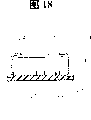
从图18到图20是表示其它实施例的图,图18是红外线传感器的剖视图,图19是表示红外线体温计的电路的方框图,图20是表示由CPU处理的处理顺序的程序方框图。18 to 20 are diagrams showing other embodiments, FIG. 18 is a sectional view of an infrared sensor, FIG. 19 is a block diagram showing a circuit of an infrared thermometer, and FIG. 20 is a program block diagram showing a processing sequence processed by a CPU.
具体实施方式Detailed ways
图1和图2是将整个红外线体温计放大很多倍表示的图。Figures 1 and 2 are diagrams showing the entire infrared thermometer magnified many times.
红外线体温计的外壳10,为了容易用手握持,整体大致是圆筒状或偏平圆筒状,头部(配置后述的红外线传感器的部分:在图中为左侧)稍稍弯曲,头部(前端部)粗一些,末端部(后端部)(在图2中为右侧)细一些。外壳10由合成树脂(例如,ABS:丙烯腈·丁二烯·苯乙烯树脂)制成。The
在外壳10内,配置有印刷电路板11,在该电路板11上,组装有温度测定电路(包括微处理机)、显示控制电路、及其它电路。Inside the
在外壳10的前端部上面(或者前面)开设有孔13,开关操作按钮12从内侧靠在该孔13上。按钮12具有向外侧突起的曲面。安装片12a从按钮12上延伸,该安装片12a的端部被夹持且固定在设置于外壳10的内面上的2个突片10a和10b之间。按钮12和安装片12a一起由树脂(例如ABS树脂)形成一体。安装片12a具有弹性。A
按钮12的内面设有操作突部12b。当从外部向外壳10的内侧推压按钮12时,突部12b与设置在电路板11上的开关14的作动器相接触。若推压1次按钮12,则上述温度测定电路的电源接通,第2次压下开始测定体温。An
在外壳10的大致中间的上面(前面)也开设有孔15。在与该孔15对应的位置,在电路板11上配置有液晶显示(LCD)装置71。即,LCD装置与其下部的衬垫74一起收纳在LCD壳72内,壳72被固定在电路板11上。LCD装置71通过橡胶接头75连接在电路板11上的配线模板上。在LCD壳72上设有由透明树脂制成的LCD罩73。LCD装置71显示测定的体温和其它信息。用户可以隔着LCD罩73从外壳10的孔15看到该信息。A
在外壳10的末端部的下面(后面)开设有电池的出入口,在此用螺钉安装有可拆卸的电池盖16。On the lower surface (rear surface) of the terminal portion of the
在外壳10的前端部设有红外线传感器20、导波管(波导管)30、探头40和导波管罩50。尤其在图3对导波管30、探头40和罩50进行了放大表示。An
红外线传感器20包括金属壳24,其内部设有红外线检测元件21。在壳24的前面开设有窗口,象是堵塞该窗口一样,窗口上设有红外线能透过的硅玻璃25(详细情况参照图18)。The
导波管30是用如铜等金属制成的圆筒状的管子,其两端30a和30b敞着口。离红外线传感器20远的开口端30a称为外端(或前端),离红外线传感器20近的开口端称为内端(或者末端)。The
探头40由合成树脂制成,是稍稍弯曲的圆锥形状,前端被截断,基部形成有安装用法兰43。法兰43上形成有螺纹孔45。在探头40的前端部,在内面形成有2个台阶部41、42。在基部附近形成有用于固定探头罩47的小的环状突部44。The
红外线传感器20保持在传感器保持架28上。即,传感器保持架28是合成树脂(例如ABS树脂)制成的带底圆筒状的零件,在底面上开设有孔28A。红外线传感器20紧紧地嵌入在该孔28A内。在保持架28上固定有电路板17。红外线传感器20的引线26与电路板17上的配线模板18相连接。在传感器保持架28的开口端28C附近,在其外周面上一体地形成有法兰28B。可以根据需要在红外线传感器20内设置温度检测元件(参照图18图的标号22),或在红外线传感器20的附近设置温度传感器。The
导波管30保持在2个导波管保持架31、32上。导波管保持架31、32也由合成树脂(例如ABS树脂)制成,大致呈圆筒状。保持架31、32的孔具有一定的直径(除凹部31D、32D之外)。导波管30紧紧地插在该孔内。保持架31、32的外周面3个台阶外径不相同,外径最小的部分31A、32A最长,外径最大的部分31B、32B向外突出呈凸缘状。在该部分31B、32B的内周面上形成有凹部31D、32D。The
导波管30嵌入在保持架31的孔内。此时,导波管30的外周面和保持架31的孔的内周面用粘接剂固定。多余的粘接剂填入凹部31D内。然后,在保持架32的孔内插有导波管30。保持架31和32在其直径大的部分31B、32B处相互对顶。The
导波管30装入传感器保持架28内。传感器保持架28的前端部28C靠在由大直径的部分32B形成的台阶部32C上。传感器保持架28进入在外壳10的前端部形成的孔10A内,其法兰28B与该孔10A的外周面相接触。导波管保持架31和导波管30的前端部进入探头40内,保持架31的小直径部分31A抵在探头40的内面的台阶部42上。探头40的法兰43用螺栓46固定在外壳10上。这样一来,探头40、导波管保持架31、32(因此导波管)、传感器保持架28(因此红外线传感器20)就被牢固地固定在外壳10的前端部。The
其状态是红外线传感器20和导波管30的大致一半位于外壳10的内部,探头40和导波管30的大致一半突出在外壳10的外部。In this state, approximately half of the
导波管30的外端(前端)30a位于与探头40的前端大致相同的位置,或位于探头40前端稍稍靠近内侧的位置。导波管30的外端部30a附近不与探头40相接触,在导波管30的前端部附近和探头40之间存在有间隙(空气层)33。The outer end (tip) 30 a of the
另外,导波管30的内端(末端)30b与红外线传感器20的传感器面(红外线入射口,即硅玻璃25)相对峙。导波管30的内端30b与红外线传感器20并不接触,在它们之间存在有间隙(空气层)34。当然导波管30的中心轴与红外线传感器20的中心轴对齐。In addition, the inner end (tip) 30 b of the
在用该红外线体温计测量体温时,将探头40的前端部插入耳孔(外耳道)内。探头40不可避免地与耳孔相接触。由于一般情况下体温比探头40的温度高,所以热会传至探头40。When measuring body temperature with this infrared thermometer, the tip of the
探头40、导波管保持架31、32、传感器保持架28用合成树脂制成。由于与金属相比合成树脂的导热系数极低(低热传导零件),可以称为绝热零件(在本说明书低热传导零件和绝热零件同义)。探头40的前端部内面和导波管30的外端部30a之间有间隙(空气层)33,由于空气层33也有绝热效果,所以,该结构传到探头40前端部的热不易传到导波管30。热既不易从探头40的前端部通过保持架31、32传到导波管30,也不易通过传感器保持架28传到红外线传感器20。The
即使耳孔的热有一点传到导波管30的外端30a,在导波管30的内端30b和红外线传感器20之间有间隙(空气层)34,也会被绝热。因此热几乎不会传到红外线传感器20。Even if the heat of the ear hole is transferred to the
这样一来,在测量体温时,人体的热几乎没有传到红外线传感器20,红外线传感器20几乎不会受到来自目标的热的不利影响。由于红外线传感器20由合成树脂(绝热零件)制成的传感器保持架28保持着,所以,也几乎不会受到周围环境的热的影响。In this way, when measuring the body temperature, the heat of the human body is hardly transmitted to the
从耳孔(鼓膜)发出的红外线,在导波管30内通过,导向红外线传感器20,能准确地进行温度的测量。如果需要的话,还可以依据温度传感器(温度检测元件)的输出对测定温度进行修正。最终的测定温度显示在LCD装置71上。Infrared rays emitted from the ear hole (tympanic membrane) pass through the
也可以使传感器保持架31、32由铝等金属制成。在这种场合,不使传感器保持架分为用标号31、32表示的2个部件,可以使这一部分31、32为一体,也不需要凹部31D、32D。从耳孔等移动到导波管30的热被金属制的传感器保持架吸收,因此,热几乎不会传到红外线传感器20。The
探头罩47由合成树脂制的环48和安装在该环48上的、由乙烯树脂或其它薄的合成树脂片材制成的袋子或护套49所构成。探头罩47用于防止病菌的感染,每一用户都换新的,即,是一次性的。通过嵌入环48,使其越过设置在探头40的基部的环状突起44,由此将探头罩47安装在探头40上。The probe cover 47 is composed of a
设置检测探头罩47(是否)已安装上的开关60。该开关60包括活动轴61。轴61具备2个端部61A和61B。端部61A较细,能滑动自如地从形成于探头40的法兰43上的孔45A(贯通的螺纹孔45)内穿过。端部61B能滑动自如地从开设于电路板17上的孔内穿过,在前端安装有触点63。轴61由于弹簧62而始终被向外侧推压。端部61A突出到探头40基部的法兰43外侧。触点63与电路板17上的配线模板64相接触(开关接通)。Set the
当探头罩47盖住探头40时,探头罩47反抗弹簧62的弹簧力,由环48推压轴60的突出的端部61A。这样一来,触点63脱离配线模板64(开关打开),能检测到探头罩47已安装。既可以将检测安装探头罩47作为开始测定体温的条件,也可以将这一信息用指示器或LCD装置71显示出来。When the
前罩19是覆盖探头40的,它拆卸自如地安装在探头40基部的法兰43的环状突部上。前罩19也由合成树脂制成,在不使用红外线体温计时盖在探头40上。The
导波管罩(盖)50的详细情况示于图4和图5。导波管罩50,其能使红外线透过的上底部51、与该上底部51的周边相连的周壁部52和从周壁部52的前端向外侧突出的凸缘(边)53用合成树脂、例如聚乙烯或聚丙烯制成一体。周壁部52朝凸缘53的方向直径渐渐地稍微有些扩大。上底部51的厚度最好是10~60μm的程度,周壁部52和凸缘53的厚度最好是200~400μm的程度。The details of the waveguide cover (cover) 50 are shown in FIGS. 4 and 5 . The
另一方面,参照图3,导波管30的外端部30a其外周面稍微削去一些,壁变薄了。该薄壁部的长度大致与罩50的深度相等。罩50盖在导波管30的外端部30a的薄壁部。这样一来,在更换探头罩47时,能防止尘埃等进入导波管30内。On the other hand, referring to FIG. 3, the outer peripheral surface of the
罩50的周壁部52的直径最小的部分的内径最好是与导波管30的外端部30a的外径相等,或稍微小一点。这样一来,罩50就紧贴在导波管30的外端部30a的外周面上。The inner diameter of the smallest diameter portion of the
导波管罩50在将导波管30与其保持架31一起装入探头40内之前,盖在导波管30上。当将导波管30装入探头40时,罩50的凸缘53抵在探头40内面的台阶部41上。由此防止罩50脱落。The
盖着导波管30的罩50在凸缘53处与探头40相接触,但由于罩50也还是用合成树脂制成的,所以,从探头40向导波管30传的热很少。The
也可以不在探头40上设置台阶部(防脱落突起)41,使罩50的凸缘53以适当的力与探头40的内面相接触,且在探头40的内面上形成环状的槽,使罩50的凸缘53嵌入到该环状槽内。也可以在罩50的周壁部52的端部、在内周面上设置向内侧突出的环状突起,在导波管30的外端部30a的外周面上形成上述环状突起嵌入的环状槽。当然,也可以不设置凸缘53,且也不在探头40上形成台阶部(防脱落突起)41。也可以使周壁部52的直径在所有的地方都相等。周壁部52的截面除了圆形之外,也可以是六角形、八角形等多角形。在这种场合下,使与多角形的周壁部内接的圆的直径大致与导波管30的外端部30a的外径相等,或比外径稍稍小一点。It is also possible not to set the step portion (fall-off prevention protrusion) 41 on the
这样一来,由于导波管罩50是将红外线能透过的上底部51和周壁部52制成一体的,所以,简单地将罩50盖在导波管上就可以,与粘接硅玻璃或用树脂薄片的环状零件固定的现有的例子相比,这样组装性好。另外,如果使罩50有足够的强度的话,即使进行擦去红外线能透过的上底部上的污物的工作,也不易破裂。In this way, since the
图6是表示变型例的图。在此,各部件的结构稍稍作了简化,图中省略了导波管罩、探头罩、前罩等。与从图1到图5所示的零件相同的零件,标同一标号,且避免重复说明。这对于以下描述的所有的变型例来说也都适用。FIG. 6 is a diagram showing a modified example. Here, the structure of each component is slightly simplified, and the waveguide cover, probe cover, front cover, etc. are omitted in the figure. Parts that are the same as those shown in Figures 1 to 5 are marked with the same reference numerals, and repeated descriptions are avoided. This also applies to all variants described below.
导波管30的内端部30b插入且支承在合成树脂制的导波管保持架36的孔内。红外线传感器20也嵌入且保持在该保持架36的孔内。再有,保持架36插入且支承在铝等金属制成的支承块35的孔内。支承块35用螺钉46A安装在外壳10上。探头40安装在支承块35上。The
导波管30的内端30b和红外线传感器20不接触(存在绝热空气层34)。由于导波管30和红外线传感器20保持在低热电导性的合成树脂制的保持架36上,所以,它们以相互绝热的状态支承着。导波管30的外端部30a不与探头40相接触。在它们之间有空气层37。即,也可以说导波管30在和探头40之间,也存在空气层37和保持架36,而且配置在绝热状态下。The
在图7中,在导波管保持架36上安装有具有直径不同的2个圆筒状部分的连接件38,红外线传感器20保持在该连接件38的大径部。导波管30的内端部30b和红外线传感器20不接触(存在空气层34),阻断了从导波管30向红外线传感器20的传热。In FIG. 7 , a
图8与图6所示的结构相比,导波管30的内端30b与红外线传感器20相接触。由于导波管30内端30b端面的表面积小,所以,即使这样接触着,传的热也不多。这种形式也可以认为含有阻断了从导波管30向红外线传感器20的传热这一概念。Compared with the structure shown in FIG. 6 in FIG. 8 , the
图9与图7所示的结构相比,导波管30的内端30b与红外线传感器20相接触,但,这种形式也可以认为含有阻断了从导波管30向红外线传感器20的传热这一概念。Compared with the structure shown in FIG. 9 in FIG. 7, the
图10a和图10b,是在图8和图9所示的状态下,为了尽量减小导波管30内端30b和红外线传感器20的接触面积(为了使即使导波管30和红外线传感器20相接触,也尽量提高绝热效果),而在内端30b上形成矩形的缺口30c或三角形的缺口30d。缺口的形状可以是半圆状等任意的形状。Fig. 10a and Fig. 10b are in the state shown in Fig. 8 and Fig. 9, in order to minimize the contact area between the
在图11所示的红外线体温计上,红外线传感器20配置在由保持架36支承的导波管30内端部30b的内部,且不与导波管30的内面相接触(设有间隙或空气层34A)。红外线传感器20安装在固定于保持架36上的电路板17A上。On the infrared thermometer shown in Fig. 11, the
在图12,红外线传感器20通过泡沫聚苯乙烯等绝热材料39支承在导波管30内。即使在这种形式下,也阻断了从导波管30向红外线传感器20的传热。In FIG. 12 , the
图13所示是在图11的结构基础上,外端30a变细一些的锥状的导波管30A。在导波管30A的内端30b和红外线传感器20之间有空气层34。FIG. 13 shows a tapered waveguide 30A in which the
从图14到图17c所示是导波管罩的变型例。From Fig. 14 to Fig. 17c are the modified examples of the waveguide cover.
图14表示将罩(探头罩)54不是盖在导波管30上,而是盖在探头40的前端部的状态。该罩54也是红外线能透过的上底部和从上底部延伸的周壁部由合成树脂制成一体的。FIG. 14 shows a state where a cover (probe cover) 54 is covered not on the
图15所示的导波管罩50A在凸缘53上形成有缺口53a。与探头40的内面接触的凸缘53的面积变小了,减少了通过凸缘53从探头40传到导波管30的热量(热传导恶化了)。In the
在图16中,在罩50B上,取代凸缘53,设有放射状且相互分离的几个突起53b。In FIG. 16 , on the cover 50B, instead of the
图17a所示的罩50C,在其周壁部52上形成有多个圆形的孔52a。在图17b中,在周壁部52上形成有多个槽52b。图17c所示是具有筛网状的周壁部52A的罩50E。这样一来,在罩的周壁部上设置孔、槽,或使周壁部是筛网,由此扩大与空气的接触面积,提高散热效果。A cover 50C shown in FIG. 17a has a plurality of circular holes 52a formed in its
从图18到图20所示是与一种红外线体温计有关的实施例,该红外线体温计在将放置在正常工作的温度范围(可测定的温度范围)之外的环境下的红外线体温计,移动到可测定温度范围内的环境下时,能明示在经过多少时间时,可变成可测定状态。Shown from Figure 18 to Figure 20 is the embodiment related to a kind of infrared thermometer, and this infrared thermometer will be placed in the environment outside the temperature range (measurable temperature range) of the normal work. When measuring an environment within the temperature range, it is possible to clearly indicate how long it takes to become measurable.
红外线体温计的结构可以是先前所示的所有实施例的任意一种结构,也可以是具有现有结构的红外线体温计。The structure of the infrared thermometer can be any structure of all the embodiments shown before, and it can also be an infrared thermometer with an existing structure.
该实施例的红外线体温计具有温度传感器。温度传感器若配置在红外线传感器的附近则是充分的,但,如图18所示,也可以将温度检测元件设置在红外线传感器的内部。The infrared thermometer of this embodiment has a temperature sensor. It is sufficient for the temperature sensor to be disposed near the infrared sensor, but as shown in FIG. 18 , the temperature detection element may also be provided inside the infrared sensor.
在图18所示的红外线传感器20上,在电路板23的中央配置有红外线检测元件21,在其附近配置有温度检测元件22。这此元件21、22被安装在电路板23上的金属制罩24覆盖。在罩24的前面的窗口24a上设有硅玻璃25。In the
图19是表示红外线体温计的电路的图。红外线检测元件(红外线传感器)21的与检测的红外线相对应的输出电压(基准电压、信号电压)被放大器85放大,由A/D转换器84转换成数字信号,输送给CPU80。同样,温度检测元件(温度传感器)22的输出也由A/D转换器84转换成数字信号,输送给CPU80。CPU80在电源开关81接通、开始测定开关82接通时,基本上依据红外线检测元件21的输出进行测定体温处理,根据需要、根据温度检测元件22的输出对测定体温进行修正,将最终确定的测定体温显示在显示器83上。CPU80在电源开关81接通时,还依据温度检测元件22的输出进行后面要描述的处理,将等待时间显示在显示器83上。Fig. 19 is a diagram showing a circuit of an infrared thermometer. The output voltage (reference voltage, signal voltage) corresponding to the detected infrared rays of the infrared detection element (infrared sensor) 21 is amplified by the amplifier 85 , converted into a digital signal by the A/D converter 84 , and sent to the CPU 80 . Similarly, the output of the temperature detecting element (temperature sensor) 22 is also converted into a digital signal by the A/D converter 84 and sent to the CPU 80 . When the power switch 81 is turned on and the measurement start switch 82 is turned on, the CPU 80 basically performs body temperature measurement processing based on the output of the
图20所示是CPU80的处理过程,在电源开关81接通时,判断是否能测定体温?如果不能,则判断到能测定体温所需的等待时间是多少,且进行显示。Shown in Fig. 20 is the processing procedure of CPU80, when power switch 81 is connected, judge whether can measure body temperature? If not, it is judged how much waiting time is required to measure the body temperature, and it is displayed.
假设可测定体温的温度范围(可测定温度范围)的上限温度为TH,下限温度为TL(例如TH=40℃,TL=10℃)。Assume that the upper limit temperature of the temperature range (measurable temperature range) in which body temperature can be measured is TH and the lower limit temperature is TL (for example, TH=40° C., TL=10° C.).
若电源开关81接通,则读取此时的温度检测元件22的输出,确定温度Ta1(步骤91)。如果测定的温度Ta1在可测定温度范围内(TL≤Ta1≤TH)(在步骤92、93都是NO),由于可以测定体温,所以,将可以测定的意思显示在显示器83上(步骤94),等待来自开始测定开关82的输入,进行体温测定处理。When the power switch 81 is turned on, the output of the
如果测定温度Ta1在可测定温度范围之外(在步骤92或93为YES),则在经过规定时间后,再次读取温度检测元件22的输出,测定此时的温度Ta2(步骤95)。If the measured temperature Ta1 is outside the measurable temperature range (YES at step 92 or 93), after a predetermined time elapses, the output of the
当红外线体温计的温度环境发生了变化(例如,将体温计从保管红外线体温计的寒冷的房间拿到了测定体温的温暖的房间),随着这一变化,体温计的内部温度,即温度检测元件22的输出也发生变化。将这一温度变化量用式ΔTa=|Ta1-Ta2|/t1算出(步骤95、96)。在此,时间t1是测定温度Ta1的时刻和测定温度Ta2的时刻之间的经过时间,既可以是事先固定的一定时间,也可以采用从步骤91的处理到步骤95的处理的经过时间。When the temperature environment of the infrared thermometer has changed (for example, the thermometer is taken from the cold room where the infrared thermometer is kept to the warm room where the body temperature is measured), along with this change, the internal temperature of the thermometer, that is, the output of the
如果分为现在温度(Ta1或Ta2)和温度的变化量ΔTa的话,能推算出到温度进入可测定的温度范围之前所需要的时间Tw。设用于推算的函数为f(Ta1,Ta2)。If it is divided into the current temperature (Ta1 or Ta2) and the temperature change amount ΔTa, the time Tw required until the temperature enters the measurable temperature range can be estimated. Let the function used for estimation be f(Ta1, Ta2).
该函数f(Ta1,Ta2)表现为是一次近似曲线。即若假定温度的变化与经过的时间成线性关系的话,则能用最简单的形式表现函数f。This function f(Ta1, Ta2) appears as a first order approximation curve. That is, if it is assumed that the change in temperature has a linear relationship with the elapsed time, the function f can be expressed in the simplest form.
若现在温度Ta1比下限温度TL低、温度上升达到下限温度TL之前的时间为等待时间Tw,则Tw由下式给出:If the current temperature Ta1 is lower than the lower limit temperature TL, and the time before the temperature rises to the lower limit temperature TL is the waiting time Tw, then Tw is given by the following formula:
Tw=f(Ta1,ΔTa)=k(TL-Ta1)/ΔTaTw=f(Ta1, ΔTa)=k(TL-Ta1)/ΔTa
在此,k是常数,一般情况下,采用1.0以上的值。Here, k is a constant, and generally takes a value of 1.0 or greater.
若现在温度Ta1比上限温度TH高、温度下降达到上限温度TH之前的时间为等待时间Tw,则Tw由下式给出:If the current temperature Ta1 is higher than the upper limit temperature TH, and the time before the temperature drops to the upper limit temperature TH is the waiting time Tw, then Tw is given by the following formula:
Tw=f(Ta1,ΔTa)=k(Ta1-TH)/ΔTaTw=f(Ta1, ΔTa)=k(Ta1-TH)/ΔTa
在上式中,也可以取代TL、TH,采用它们的中间温度TM(=(TL+TH)/2)。In the above formula, instead of TL and TH, their intermediate temperature TM (=(TL+TH)/2) may be used.
也可以取代温度检测元件的输出,利用红外线检测元件的基准输出电压,推算等待时间Tw。Instead of the output of the temperature detection element, the waiting time Tw may be estimated using the reference output voltage of the infrared detection element.
若算出等待时间Tw(步骤98),则将该算出的时间Tw显示于显示器83(步骤99)。When the waiting time Tw is calculated (step 98), the calculated time Tw is displayed on the display 83 (step 99).
这样一来,用户可以知道到能使用红外线体温计的大致的时间。In this way, the user can know the approximate time until the infrared thermometer can be used.
Claims (2)
Applications Claiming Priority (6)
| Application Number | Priority Date | Filing Date | Title |
|---|---|---|---|
| JP298281/1998 | 1998-10-20 | ||
| JP29828198 | 1998-10-20 | ||
| JP306716/1998 | 1998-10-28 | ||
| JP30671698 | 1998-10-28 | ||
| JP30793498 | 1998-10-29 | ||
| JP307934/1998 | 1998-10-29 |
Related Parent Applications (1)
| Application Number | Title | Priority Date | Filing Date |
|---|---|---|---|
| CNB998123153A Division CN1220468C (en) | 1998-10-20 | 1999-10-20 | Infrared thermometer |
Publications (2)
| Publication Number | Publication Date |
|---|---|
| CN1615793A CN1615793A (en) | 2005-05-18 |
| CN1316938C true CN1316938C (en) | 2007-05-23 |
Family
ID=27338210
Family Applications (3)
| Application Number | Title | Priority Date | Filing Date |
|---|---|---|---|
| CNB2004100973322A Expired - Lifetime CN1316938C (en) | 1998-10-20 | 1999-10-20 | Infrared thermometer |
| CNB998123153A Expired - Lifetime CN1220468C (en) | 1998-10-20 | 1999-10-20 | Infrared thermometer |
| CNB2004100588768A Expired - Lifetime CN1299637C (en) | 1998-10-20 | 1999-10-20 | Infrared thermometer |
Family Applications After (2)
| Application Number | Title | Priority Date | Filing Date |
|---|---|---|---|
| CNB998123153A Expired - Lifetime CN1220468C (en) | 1998-10-20 | 1999-10-20 | Infrared thermometer |
| CNB2004100588768A Expired - Lifetime CN1299637C (en) | 1998-10-20 | 1999-10-20 | Infrared thermometer |
Country Status (7)
| Country | Link |
|---|---|
| US (1) | US6513970B1 (en) |
| EP (2) | EP1521070B1 (en) |
| JP (1) | JP3646652B2 (en) |
| CN (3) | CN1316938C (en) |
| AT (2) | ATE362614T1 (en) |
| DE (2) | DE69934508T2 (en) |
| WO (1) | WO2000022978A1 (en) |
Cited By (1)
| Publication number | Priority date | Publication date | Assignee | Title |
|---|---|---|---|---|
| TWI834375B (en) * | 2022-11-08 | 2024-03-01 | 長庚學校財團法人長庚科技大學 | digital thermometer |
Families Citing this family (49)
| Publication number | Priority date | Publication date | Assignee | Title |
|---|---|---|---|---|
| WO2001096825A1 (en) * | 2000-06-13 | 2001-12-20 | Omron Corporation | Pyrometer |
| SE522297C2 (en) * | 2001-05-17 | 2004-01-27 | Biodisk Ab | Method and apparatus for the application of thin articles and the use of packaging for the thin articles |
| JP2002345761A (en) * | 2001-05-22 | 2002-12-03 | Omron Corp | Infrared thermometer probe |
| JP3900865B2 (en) * | 2001-06-04 | 2007-04-04 | オムロンヘルスケア株式会社 | Infrared thermometer, infrared thermometer temperature state estimation method, information notification method, and measurement operation management method |
| US6749334B2 (en) * | 2002-08-09 | 2004-06-15 | Radiant Innovation Inc. | Ear thermometer probe structure |
| WO2004043256A2 (en) * | 2002-11-12 | 2004-05-27 | Prourocare, Inc. | Intelligent medical device barrier |
| US7434991B2 (en) | 2002-12-12 | 2008-10-14 | Covidien Ag | Thermal tympanic thermometer |
| PT1570246E (en) | 2002-12-12 | 2009-04-09 | Covidien Ag | THERMOMETER THERMOMETER FOR TIMPANS |
| US20050002437A1 (en) * | 2003-07-02 | 2005-01-06 | Jacob Fraden | Probe for a body cavity |
| US8795168B2 (en) | 2003-07-17 | 2014-08-05 | Cadi Scientific Pte Ltd. | Method and system for capturing and monitoring a physiological parameter and movement within an area of at least one person |
| US7270476B2 (en) * | 2003-08-21 | 2007-09-18 | Omron Healthcare Co., Ltd. | Electronic clinical thermometer with quick temperature estimating device |
| EP2373963B1 (en) | 2008-12-29 | 2023-03-01 | KAZ Europe SA | Probe cover with matching feature for a medical thermometer |
| US8876373B2 (en) | 2009-04-09 | 2014-11-04 | Welch Allyn, Inc. | IR thermometry probe cover |
| US12492949B2 (en) | 2009-04-09 | 2025-12-09 | Welch Allyn, Inc. | IR thermometry probe cover |
| USD787683S1 (en) | 2009-04-09 | 2017-05-23 | Welch Allyn, Inc. | Cover for a probe |
| USD685482S1 (en) | 2009-04-09 | 2013-07-02 | Welch Allyn, Inc. | Cover for a probe or the like |
| CN102772199A (en) * | 2011-05-13 | 2012-11-14 | 优盛医学科技股份有限公司 | Non-contact temperature sensing device capable of measuring at fixed distance and temperature measuring method thereof |
| CN102327113A (en) * | 2011-09-28 | 2012-01-25 | 深圳市东迪欣科技有限公司 | Temperature measurement head structure and thermometer |
| WO2013044470A1 (en) * | 2011-09-28 | 2013-04-04 | Zhao Zhigang | Temperature measurement head structure and clinical thermometer |
| DE102012215690A1 (en) * | 2012-09-05 | 2014-03-06 | Robert Bosch Gmbh | Temperature measuring device, as well as methods for temperature measurement |
| GB2512813A (en) * | 2013-02-11 | 2014-10-15 | Brother Max Ltd | Electronic thermometer |
| US20150127293A1 (en) * | 2013-09-09 | 2015-05-07 | Eugene Terry Tatum | Time of death probe and recorder |
| US9575560B2 (en) | 2014-06-03 | 2017-02-21 | Google Inc. | Radar-based gesture-recognition through a wearable device |
| US9921660B2 (en) | 2014-08-07 | 2018-03-20 | Google Llc | Radar-based gesture recognition |
| US9811164B2 (en) | 2014-08-07 | 2017-11-07 | Google Inc. | Radar-based gesture sensing and data transmission |
| US9588625B2 (en) | 2014-08-15 | 2017-03-07 | Google Inc. | Interactive textiles |
| US10268321B2 (en) | 2014-08-15 | 2019-04-23 | Google Llc | Interactive textiles within hard objects |
| US9778749B2 (en) | 2014-08-22 | 2017-10-03 | Google Inc. | Occluded gesture recognition |
| US11169988B2 (en) | 2014-08-22 | 2021-11-09 | Google Llc | Radar recognition-aided search |
| US9600080B2 (en) | 2014-10-02 | 2017-03-21 | Google Inc. | Non-line-of-sight radar-based gesture recognition |
| US10064582B2 (en) | 2015-01-19 | 2018-09-04 | Google Llc | Noninvasive determination of cardiac health and other functional states and trends for human physiological systems |
| US10016162B1 (en) * | 2015-03-23 | 2018-07-10 | Google Llc | In-ear health monitoring |
| US9983747B2 (en) | 2015-03-26 | 2018-05-29 | Google Llc | Two-layer interactive textiles |
| US9848780B1 (en) | 2015-04-08 | 2017-12-26 | Google Inc. | Assessing cardiovascular function using an optical sensor |
| KR102229658B1 (en) | 2015-04-30 | 2021-03-17 | 구글 엘엘씨 | Type-agnostic rf signal representations |
| KR102002112B1 (en) | 2015-04-30 | 2019-07-19 | 구글 엘엘씨 | RF-based micro-motion tracking for gesture tracking and recognition |
| US10139916B2 (en) | 2015-04-30 | 2018-11-27 | Google Llc | Wide-field radar-based gesture recognition |
| US10080528B2 (en) | 2015-05-19 | 2018-09-25 | Google Llc | Optical central venous pressure measurement |
| US9693592B2 (en) | 2015-05-27 | 2017-07-04 | Google Inc. | Attaching electronic components to interactive textiles |
| US10088908B1 (en) | 2015-05-27 | 2018-10-02 | Google Llc | Gesture detection and interactions |
| US10376195B1 (en) | 2015-06-04 | 2019-08-13 | Google Llc | Automated nursing assessment |
| US10817065B1 (en) | 2015-10-06 | 2020-10-27 | Google Llc | Gesture recognition using multiple antenna |
| WO2017079484A1 (en) | 2015-11-04 | 2017-05-11 | Google Inc. | Connectors for connecting electronics embedded in garments to external devices |
| JP5996139B1 (en) * | 2016-03-31 | 2016-09-21 | 興和株式会社 | Infrared thermometer |
| WO2017192167A1 (en) | 2016-05-03 | 2017-11-09 | Google Llc | Connecting an electronic component to an interactive textile |
| US10175781B2 (en) | 2016-05-16 | 2019-01-08 | Google Llc | Interactive object with multiple electronics modules |
| US10579150B2 (en) | 2016-12-05 | 2020-03-03 | Google Llc | Concurrent detection of absolute distance and relative movement for sensing action gestures |
| EP3603494B1 (en) * | 2017-03-21 | 2022-03-16 | LG Electronics Inc. | Body temperature measurement device |
| CN107290066A (en) * | 2017-08-21 | 2017-10-24 | 优利德科技(中国)有限公司 | A kind of protection structure of LCD protection components and Non-contact Infrared Temperature Measurement rifle |
Citations (2)
| Publication number | Priority date | Publication date | Assignee | Title |
|---|---|---|---|---|
| JPH08191800A (en) * | 1995-01-18 | 1996-07-30 | Terumo Corp | Thermometer and clinical thermometer |
| US5723847A (en) * | 1995-08-07 | 1998-03-03 | Bosch-Siemens Hausgeraete Gmbh | Method for determining and displaying the remaining time in a treatment program in a household appliance and electronic control unit for performing the method |
Family Cites Families (19)
| Publication number | Priority date | Publication date | Assignee | Title |
|---|---|---|---|---|
| US4541734A (en) * | 1982-06-24 | 1985-09-17 | Terumo Kabushiki Kaisha | Electronic clinical thermometer, and method of measuring body temperature |
| FR2541453B1 (en) * | 1982-12-21 | 1985-08-30 | Terumo Corp | ELECTRONIC MEDICAL THERMOMETER AND METHOD FOR MEASURING BODY TEMPERATURE |
| JPS60187830A (en) * | 1984-03-07 | 1985-09-25 | Omron Tateisi Electronics Co | Electronic clinical thermometer |
| JPS60157031A (en) * | 1984-01-27 | 1985-08-17 | Terumo Corp | Electronic clinical thermometer and method for measuring bodily temperature |
| US5179936A (en) | 1984-10-23 | 1993-01-19 | Intelligent Medical Systems, Inc. | Disposable speculum with membrane bonding ring |
| GB2197724B (en) * | 1986-11-05 | 1990-12-19 | Citizen Watch Co Ltd | Predictive operation type electronic clinical thermometer |
| JPH0795004B2 (en) * | 1986-12-24 | 1995-10-11 | テルモ株式会社 | Body temperature measuring device |
| JP2828258B2 (en) * | 1988-04-08 | 1998-11-25 | シチズン時計株式会社 | Radiation thermometer |
| US4895164A (en) | 1988-09-15 | 1990-01-23 | Telatemp Corp. | Infrared clinical thermometer |
| JP2983699B2 (en) | 1991-07-16 | 1999-11-29 | 三洋電機株式会社 | Multi-disc player |
| US5392031A (en) * | 1992-03-17 | 1995-02-21 | Terumo Kabushiki Kaisha | Electronic clinical thermometer |
| CN1168623A (en) * | 1994-02-28 | 1997-12-24 | 伊康诺梅逊公司 | Infrared tympanic thermometer |
| JP3553674B2 (en) * | 1995-02-14 | 2004-08-11 | テルモ株式会社 | Probe cover attachment for thermometer |
| CN1089162C (en) | 1995-12-28 | 2002-08-14 | 欧姆龙株式会社 | Infrared thermometer |
| JP2000510721A (en) * | 1996-05-07 | 2000-08-22 | サーモスキャン,インコーポレーテッド | Protective cover for infrared thermometer |
| JP3514138B2 (en) * | 1998-09-29 | 2004-03-31 | テルモ株式会社 | Probe cover removal mechanism and ear thermometer |
| US6349269B1 (en) * | 1998-12-11 | 2002-02-19 | Dell U.S.A., L.P. | Thermal management data prediction system |
| US6270252B1 (en) * | 1999-05-18 | 2001-08-07 | Alaris Medical Systems, Inc. | Predictive temperature measurement system |
| US6332867B1 (en) * | 1999-06-09 | 2001-12-25 | Vsm Technology Inc. | Method and apparatus for measuring values of physiological parameters |
-
1999
- 1999-10-20 CN CNB2004100973322A patent/CN1316938C/en not_active Expired - Lifetime
- 1999-10-20 EP EP04027889A patent/EP1521070B1/en not_active Expired - Lifetime
- 1999-10-20 CN CNB998123153A patent/CN1220468C/en not_active Expired - Lifetime
- 1999-10-20 DE DE69934508T patent/DE69934508T2/en not_active Expired - Lifetime
- 1999-10-20 DE DE69936108T patent/DE69936108T2/en not_active Expired - Lifetime
- 1999-10-20 US US09/807,828 patent/US6513970B1/en not_active Expired - Fee Related
- 1999-10-20 WO PCT/JP1999/005774 patent/WO2000022978A1/en not_active Ceased
- 1999-10-20 JP JP2000576759A patent/JP3646652B2/en not_active Expired - Lifetime
- 1999-10-20 CN CNB2004100588768A patent/CN1299637C/en not_active Expired - Lifetime
- 1999-10-20 EP EP99949313A patent/EP1123685B1/en not_active Expired - Lifetime
- 1999-10-20 AT AT04027889T patent/ATE362614T1/en not_active IP Right Cessation
- 1999-10-20 AT AT99949313T patent/ATE348565T1/en not_active IP Right Cessation
Patent Citations (2)
| Publication number | Priority date | Publication date | Assignee | Title |
|---|---|---|---|---|
| JPH08191800A (en) * | 1995-01-18 | 1996-07-30 | Terumo Corp | Thermometer and clinical thermometer |
| US5723847A (en) * | 1995-08-07 | 1998-03-03 | Bosch-Siemens Hausgeraete Gmbh | Method for determining and displaying the remaining time in a treatment program in a household appliance and electronic control unit for performing the method |
Cited By (1)
| Publication number | Priority date | Publication date | Assignee | Title |
|---|---|---|---|---|
| TWI834375B (en) * | 2022-11-08 | 2024-03-01 | 長庚學校財團法人長庚科技大學 | digital thermometer |
Also Published As
| Publication number | Publication date |
|---|---|
| DE69934508D1 (en) | 2007-02-01 |
| WO2000022978A1 (en) | 2000-04-27 |
| DE69936108T2 (en) | 2008-02-14 |
| US6513970B1 (en) | 2003-02-04 |
| ATE348565T1 (en) | 2007-01-15 |
| DE69936108D1 (en) | 2007-06-28 |
| CN1615793A (en) | 2005-05-18 |
| CN1220468C (en) | 2005-09-28 |
| EP1123685A4 (en) | 2001-11-21 |
| ATE362614T1 (en) | 2007-06-15 |
| EP1123685A1 (en) | 2001-08-16 |
| EP1123685B1 (en) | 2006-12-20 |
| EP1521070A1 (en) | 2005-04-06 |
| DE69934508T2 (en) | 2007-09-27 |
| EP1521070B1 (en) | 2007-05-16 |
| CN1557251A (en) | 2004-12-29 |
| CN1299637C (en) | 2007-02-14 |
| JP3646652B2 (en) | 2005-05-11 |
| CN1323179A (en) | 2001-11-21 |
Similar Documents
| Publication | Publication Date | Title |
|---|---|---|
| CN1316938C (en) | Infrared thermometer | |
| CN1089162C (en) | Infrared thermometer | |
| JPWO2000022978A1 (en) | infrared thermometer | |
| CN1195446C (en) | Radiation thermometer | |
| CN1714283A (en) | Thermal tympanic thermometer tip | |
| US8136985B2 (en) | IR thermometer thermal isolation tip assembly | |
| CN1387029A (en) | Infrared thermometer | |
| CN1118692C (en) | Radiation pyrometer | |
| US20100130838A1 (en) | Infrared Temperature Measurement of Strip | |
| CN1185983C (en) | Radiation clinical thermometer | |
| TW200847992A (en) | Ear plug-in type clinical thermometer | |
| US20070100253A1 (en) | Electronic thermometer with sensor location | |
| US20090129435A1 (en) | Probe structure | |
| JP3770265B2 (en) | Infrared thermometer | |
| CN1794125A (en) | Device for temperature control of a measuring cell in an analyzer, and measuring cell which can be exchangeably inserted in an analyzer | |
| US20070206657A1 (en) | Probe structure | |
| CN201269778Y (en) | Ear thermometer and probe head thereof | |
| CN223179647U (en) | Ear temperature detection device | |
| JP2000254103A (en) | Radiation thermometer | |
| CN2759382Y (en) | Ear thermometer | |
| CN119147102A (en) | Ear temperature detection device | |
| JP2000014648A (en) | Ear type thermometer | |
| JP2003126048A (en) | Thermometer and sensor cap of the thermometer | |
| CN1254089A (en) | eardrum thermometer | |
| HK1024294B (en) | Radiation pyrometer |
Legal Events
| Date | Code | Title | Description |
|---|---|---|---|
| C06 | Publication | ||
| PB01 | Publication | ||
| C10 | Entry into substantive examination | ||
| SE01 | Entry into force of request for substantive examination | ||
| ASS | Succession or assignment of patent right |
Owner name: OMRON HEALTHY MEDICAL TREATMENT ENTERPRISE CO., L Free format text: FORMER OWNER: OMRON CORP. Effective date: 20050805 |
|
| C41 | Transfer of patent application or patent right or utility model | ||
| TA01 | Transfer of patent application right |
Effective date of registration: 20050805 Address after: Kyoto Japan Applicant after: Omron Healthcare Co., Ltd. Address before: Kyoto Japan Applicant before: Omron Corporation |
|
| C14 | Grant of patent or utility model | ||
| GR01 | Patent grant | ||
| CX01 | Expiry of patent term |
Granted publication date: 20070523 |
|
| CX01 | Expiry of patent term |