[go: up one dir, main page]

CN1316156A - Method and apparatus for maintaining document focus during non-contact scanning - Google Patents

Method and apparatus for maintaining document focus during non-contact scanning Download PDF

Info

Publication number
CN1316156A
CN1316156A CN99809016A CN99809016A CN1316156A CN 1316156 A CN1316156 A CN 1316156A CN 99809016 A CN99809016 A CN 99809016A CN 99809016 A CN99809016 A CN 99809016A CN 1316156 A CN1316156 A CN 1316156A
Authority
CN
China
Prior art keywords
document
platen
scanning
scanner
rollers
Prior art date
Legal status (The legal status is an assumption and is not a legal conclusion. Google has not performed a legal analysis and makes no representation as to the accuracy of the status listed.)
Granted
Application number
CN99809016A
Other languages
Chinese (zh)
Other versions
CN1248481C (en
Inventor
埃里克·拉金
安娜·常
戴维·里纳尔迪斯
海沦·肖风西
Current Assignee (The listed assignees may be inaccurate. Google has not performed a legal analysis and makes no representation or warranty as to the accuracy of the list.)
Lite On Technology Corp
Original Assignee
XULI CO Ltd
Priority date (The priority date is an assumption and is not a legal conclusion. Google has not performed a legal analysis and makes no representation as to the accuracy of the date listed.)
Filing date
Publication date
Application filed by XULI CO Ltd filed Critical XULI CO Ltd
Publication of CN1316156A publication Critical patent/CN1316156A/en
Application granted granted Critical
Publication of CN1248481C publication Critical patent/CN1248481C/en
Anticipated expiration legal-status Critical
Expired - Fee Related legal-status Critical Current

Links

Images

Classifications

    • HELECTRICITY
    • H04ELECTRIC COMMUNICATION TECHNIQUE
    • H04NPICTORIAL COMMUNICATION, e.g. TELEVISION
    • H04N1/00Scanning, transmission or reproduction of documents or the like, e.g. facsimile transmission; Details thereof
    • H04N1/00519Constructional details not otherwise provided for, e.g. housings, covers
    • H04N1/00538Modular devices, i.e. allowing combinations of separate components, removal or replacement of components
    • H04N1/00541Modular devices, i.e. allowing combinations of separate components, removal or replacement of components with detachable image reading apparatus
    • HELECTRICITY
    • H04ELECTRIC COMMUNICATION TECHNIQUE
    • H04NPICTORIAL COMMUNICATION, e.g. TELEVISION
    • H04N1/00Scanning, transmission or reproduction of documents or the like, e.g. facsimile transmission; Details thereof
    • H04N1/04Scanning arrangements, i.e. arrangements for the displacement of active reading or reproducing elements relative to the original or reproducing medium, or vice versa
    • H04N1/10Scanning arrangements, i.e. arrangements for the displacement of active reading or reproducing elements relative to the original or reproducing medium, or vice versa using flat picture-bearing surfaces
    • H04N1/107Scanning arrangements, i.e. arrangements for the displacement of active reading or reproducing elements relative to the original or reproducing medium, or vice versa using flat picture-bearing surfaces with manual scanning
    • H04N1/1077Arrangements for facilitating movement over the scanned medium, e.g. disposition of rollers
    • HELECTRICITY
    • H04ELECTRIC COMMUNICATION TECHNIQUE
    • H04NPICTORIAL COMMUNICATION, e.g. TELEVISION
    • H04N1/00Scanning, transmission or reproduction of documents or the like, e.g. facsimile transmission; Details thereof
    • H04N1/04Scanning arrangements, i.e. arrangements for the displacement of active reading or reproducing elements relative to the original or reproducing medium, or vice versa
    • H04N1/12Scanning arrangements, i.e. arrangements for the displacement of active reading or reproducing elements relative to the original or reproducing medium, or vice versa using the sheet-feed movement or the medium-advance or the drum-rotation movement as the slow scanning component, e.g. arrangements for the main-scanning
    • H04N1/121Feeding arrangements
    • HELECTRICITY
    • H04ELECTRIC COMMUNICATION TECHNIQUE
    • H04NPICTORIAL COMMUNICATION, e.g. TELEVISION
    • H04N1/00Scanning, transmission or reproduction of documents or the like, e.g. facsimile transmission; Details thereof
    • H04N1/04Scanning arrangements, i.e. arrangements for the displacement of active reading or reproducing elements relative to the original or reproducing medium, or vice versa
    • H04N1/19Scanning arrangements, i.e. arrangements for the displacement of active reading or reproducing elements relative to the original or reproducing medium, or vice versa using multi-element arrays
    • H04N1/191Scanning arrangements, i.e. arrangements for the displacement of active reading or reproducing elements relative to the original or reproducing medium, or vice versa using multi-element arrays the array comprising a one-dimensional array, or a combination of one-dimensional arrays, or a substantially one-dimensional array, e.g. an array of staggered elements
    • H04N1/192Simultaneously or substantially simultaneously scanning picture elements on one main scanning line
    • H04N1/193Simultaneously or substantially simultaneously scanning picture elements on one main scanning line using electrically scanned linear arrays, e.g. linear CCD arrays
    • HELECTRICITY
    • H04ELECTRIC COMMUNICATION TECHNIQUE
    • H04NPICTORIAL COMMUNICATION, e.g. TELEVISION
    • H04N2201/00Indexing scheme relating to scanning, transmission or reproduction of documents or the like, and to details thereof
    • H04N2201/04Scanning arrangements
    • H04N2201/0402Arrangements not specific to a particular one of the scanning methods covered by groups H04N1/04 - H04N1/207
    • H04N2201/0456Arrangements not specific to a particular one of the scanning methods covered by groups H04N1/04 - H04N1/207 for maintaining a predetermined distance between the scanning elements and the picture-bearing surface

Landscapes

  • Engineering & Computer Science (AREA)
  • Multimedia (AREA)
  • Signal Processing (AREA)
  • Facsimile Scanning Arrangements (AREA)
  • Automatic Focus Adjustment (AREA)

Abstract

本发明涉及一种能够利用图像传感器器件(201)对诸如照片(101)之类的文档进行扫描的扫描设备,上述图像传感器使用了具有窄聚焦深度的光学器件(307),它能够在扫描期间避免与文档产生接触。也就是说,传感器器件的聚焦区(311)与图像传感器器件(201)有一定的距离。该扫描设备包括一个定位机构(203,204),它能够在扫描期间使文档的正面保持处于聚焦区之中。

Figure 99809016

The present invention relates to a scanning device capable of scanning a document such as a photograph (101) using an image sensor device (201), wherein the image sensor uses an optical device (307) with a narrow focus depth, which can avoid contact with the document during scanning. That is, the focus area (311) of the sensor device is at a certain distance from the image sensor device (201). The scanning device includes a positioning mechanism (203, 204) which can keep the front side of the document in the focus area during scanning.

Figure 99809016

Description

Be used at noncontact scan period maintenance document method of focusing and device
The present invention relates to image scanning.Specifically, the present invention relates to the design and the enforcement of scanning device, this scanning device can be by not placing document on the focus of scanning device producing on the front of document slidably, thereby the document of front rapid wear is scanned.
To generally finish such as the physical-file picture material work of " scanning " one-tenth digital form in high quality of business documentation, as document scanner and the facsimile machine that is connected with computer by business machine.Document scanner can (for example) become digital form to be included in the computer documents image transitions.Facsimile machine sends to other facsimile machine by telephone line with digital information, and then the latter will restore the fax of original document.Document is finished an image sensor cell from the work that physical form converts digital form to.Imageing sensor is generally charge-coupled device (CCD) or silicon image sensor.Illumination is provided by a lighting apparatus, and the optics that is used for document surfaces is focused to imageing sensor is then provided by one or more level crossings and lens.This optical texture can allow dwindling of text or amplify also can controlling filed the degree of depth.The depth of field of this structure can be bigger, utilizes this optical texture just can scan under the situation that does not need generation contact (to call " noncontact scanning " in the following text).
Recently, a kind of small integrated device that is called contact-type image sensor (CIS) has begun to be used as image sensor cell.CIS generally comprise the lighting device that focusing optics is narrow focusing lens array depth (as, gradient index lens array is also referred to as selfoc lens array), and one or morely be in a sensor array within the encapsulation.This small units is normally sealed, and illumination and file scanning are undertaken by single " scanning window ".Scanning device is designed to like this, that is, CIS image sensor cell scanning be placed in this unit the focus place document laterally, document vertically then obtain scanning by relatively moving of being produced between document and the sensor unit.Compared with former sensor technology, the advantage of CIS is: be easy to make, reduced parts number, moving component has still less reduced cost, the light path of integrated optics and environment control.One of its shortcoming is that its depth of focus is too narrow, and this point will obtain explanation in the back.
Relatively moving of being produced between document and the sensor unit can obtain by one of two kinds of structures.First kind is generally used by " flat board " scanner and photocopier.In this structure, CIS does not contain physical scan instrument window usually, document be placed on its down be image reading apparatus cellotone sheet the top and focus on through this transparent material.The CIS picture sweep unit vertically moves the effect lower edge of driving mechanism document, and it is static that document then keeps.This structure is not a main field of application of the present invention.
Second kind of structure is suitable for using in facsimile machine, hand-held scanner and paper feeding type scanner, and the present invention is mainly used in this field.In this structure, the CIS unit is assembled into and makes the focus of transducer one lens combination and the outer surface of the window that a fundamental sum CIS is fixed together coincide.The scanning window that document must be placed to substantially with being used for to document focuses on contacts, and in scan period, in order to keep making document be in shallow focal zone, then must keep contacting of document and sensor window.Owing to used this structure, make that the sealing contact-type image sensor has obtained using widely in facsimile machine and other cheap document scanner, and use the equipment of this structure must be designed to make the document that is scanned to slip over scanner window.
Because the above-mentioned advantage (as: durable relatively and cheap) of contact-type image sensor structure, so adopt the facsimile machine of this technology and low price black and white gray scale document scanner almost to be seen everywhere.But contact-type image sensor has very little depth of field, approximately has only 2/10ths millimeters, could realize high-quality scanning so only have under the good situation about contacting at document and scanning window.The depth of field of contact-type image sensor relative narrower can cause the design problem that can not occur in depth of field can reformed imageing sensor.Recently the colored contact-type image sensor that occurs also has another design problem: color scanner is used to photo and printed document, so contact-type image sensor must be compatible mutually with photo media.Not problem with contacting of polytype general file material (as: level and smooth paper).But, can not can not scan by the level and smooth inswept material of scanning element some based on the scanner of contact-type image sensor technology.Specifically, contact-type image sensor can not be used for photo document reliably.The present the following aspects of this defect map:
1. because the software feature and the water absorption character of picture photosensitive emulsion, " wetting " may occur between photo document and the scanning window contacts, when this happens, coefficient of friction between document and the scanning window will increase, thereby document is bonded on the scanning window, and then causes the document conveying to go wrong.
2. the optical characteristics at the document/scanning window interface between wet contact point and the non-wet contact point is different.Part is bonded on the image that the photo document on the window can cause scanning and striped and spot occur, is referred to as " stain " herein.
3. soft picture photosensitive emulsion is easier to be damaged than paper spare document.Photo document may owing to its with level and smooth contact of window in produce directly contact or between document and scanning window, have dust granule to be damaged or scratch.
The defective that scans with this class scanning technique comparison film has been known by the manufacturers of scanner, thereby some manufacturer has proposed to protect with clean plastics the way of picture surface when scanned photograph.So with regard to need to solve with CIS document (as photo) is occurred when scanning with the scanning window bonding or be touched the problem of damage.
In sum, compare with conventional art, CIS has lot of advantages, comprising: component count that reduces and cost and be convenient to make and realize.The meeting of CIS brings the characteristics of problem to be, its less depth of focus requires scan period accurately to place document.In the CIS scanner, this measure is finished through the following steps: 1) pass and focus on the outer surface of scanning window, and 2) document was dragged window, and in the focusing of scan period maintenance to document.Above-mentioned steps can produce the image of a focusing, but but can make scanner the holding paper situation occur, thereby can damage the document of rapid wear, perhaps also may cause certain type optical problem.A kind of solution is that scanner window is designed to be able to reduce bonding with document.The example of this method can be at U.S. Patent Application Serial Number 09/xxx, and xxx (application on July 16th, 1998) is entitled as " being used for the modifying device by utilizing contact-type image sensor that the document such as photo is scanned " (inventor: people such as Craig) see.The another kind of solution that herein will illustrate is to focus light at away from comprising into document detent mechanism on the point of imageing sensor and in the design of scanner.
In the present invention, can produce focus according to (for example) and CIS mode much at one and be positioned at, and it has had whole advantages of CIS apart from the imageing sensor of image sensing body certain distance.From an aspect, the document detent mechanism can keep focusing to document by following measure: 1) it provides a cover registration roller, and they are fixed with respect to imageing sensor substantially, and as object of reference to be used for the location of document; 2) platen that is used for support document, its motion is subjected to the restriction of spring and link gear.By the motion of correct restriction platen, mobile just can being controlled so as to of document may both remain on the focus in damaged front document, only produced with registration roller again to contact, and can also slide on platen in the while back side of document.Take that these characteristics of the present invention and prior art are described to be contained a spring structure (its example can be at the United States Patent (USP) 5 to people such as Oliver Wang in order to the scanner that keeps document to contact with the CIS unit, 463, see in 256) compare, people's such as Wang mechanism needs CIS and document to have to contact to keep the focusing of document, do not having under the situation of this contact, it will can not worked.And from one aspect of the present invention, because its spring mechanism is subjected to mechanical constraint, so just can not produce the focusing that keeps document under the situation about contacting with image-generating unit.
An object of the present invention is to allow CIS class scanner to can be used for scanning to having the document that is inclined to the scanning window bonding.
Another object of the present invention is to reduce the situation that the document that occurred in photo document scan period blocks.
A further object of the invention is to reduce the stain situation that is occurred in photo document scan period.
A further object of the invention is to reduce the document with rapid wear imaging surface being carried out the document that CIS scan period occurred to scratch situation.
A further object of the invention is that document is remained in the focal zone of contactless imageing sensor, and does not have sliding friction substantially on the front of document.
Though hereinafter the modification that is used to reduce friction is illustrated, concerning those skilled in the art, it is clear understandable that other modification also will become, and the present invention is not subjected to the restriction of specific modification described in the literary composition.In addition, although the present invention is designed to the scanning of photo, it can be common to also that all scannings that need avoid sliding contact are used and among common scanning uses.
Fig. 1 is the perspective view of scanning device in scan period.
Fig. 2 is the sectional view of preferred embodiment, and it has demonstrated relatively moving between imageing sensor and the document controlling organization.
Fig. 3 is the schematic cross-section of preferred embodiment that is connected with the contactless imageing sensor of scan roller.
Fig. 4 is the perspective view of preferred embodiment that is connected with the image sensor cell of scan roller.
Fig. 5 is that wherein document is subjected to the sectional view of the preferred embodiment of the document supporting device that a platen supports.
Fig. 6 is to use the perspective view of another embodiment of the document supporting device of a deflection.
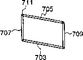
Fig. 7 is to use the vertical view of another embodiment of the document supporting device of a four bar linkage.
Fig. 8 is document moves from the embodiment of the document supporting device of the use one four bar linkage shown in Figure 7 direction end view of looking resulting.
Fig. 9 is the sectional view that has another embodiment of the detent mechanism of responding to the document bending.
Figure 10 is the perspective view according to hand-held scanner embodiment of the present invention.
Figure 11 is the sectional view that has with another embodiment of the scanning platen that is of coupled connections of casing and imageing sensor and platen keeping parallelism.
Figure 12 is the sectional view that platen and imageing sensor keep another embodiment of being parallel to each other.
Figure 13 is the sectional view of the preferred embodiment of platen.Reference number in the accompanying drawing
100 scanning devices
101 documents
103 scanning device fuselages
The output of 105 imageing sensors
107 imageing sensor electronic equipments
109 useful outputs
111 power supplys
113 scanning device openings
114 scanning device openings
201 imageing sensors
203 first scanner rollers
204 second scanner rollers
205 first scanner roller support
206 second scanner roller support
209 platens
211 spring mechanisms
213 torsion bars
215 first scanner roller turn lines
216 second scanner roller turn lines
217 torsion bar fixing holes
219 torsion bar fixing holes
221 document fronts
223 orientations and force application mechanism
301 transducer casings
303 image sensor arrays
305 substrates
307 focusing optics (narrow depth of field)
309 light sources (lighting unit)
311 focal zones
313 light beams
601 deflection horizontal components
603 deflection horizontal components
The vertical part of 605 deflections
The vertical part of 606 deflections
607 platens
The joint of 613 platens and deflection
The joint of 615 scanning device fuselages and deflection
The connection of 703 four bar linkages (non-vertical) connecting rod
The connection of 705 four bar linkages (non-vertical) connecting rod
The vertical connecting rod of 707 four bar linkages
The vertical connecting rod of 709 four bar linkages
713 linkage one scan instrument device body supporting members
715 linkage one scan instrument platen plate supporting parts
803 scanning device fuselages
811 spring mechanisms
900 scanning devices
901 scanning device fuselages
905 first scanner rollers
906 second scanner rollers
907 first scanner roller support
908 second scanner roller support
909 platens
911 orientations and force application mechanism
913 retainer springs
915 torsion bars
917 first location rollers
918 second location rollers
919 first location roller support rotational lines
920 second location roller support rotational lines
921 first location roller support
922 second location roller support
923 first location roller support rotational lines
924 second location roller support rotational lines
1010 working faces
1101 platens
1,103 first scanner rollers
1,104 second scanner rollers
1105 orientations and force application mechanism
1107 torsion bars
1109 spring mechanisms
1201 platens
1,203 first scanner rollers
1,204 second scanner rollers
1,205 first orientation and force application mechanisms
1,207 second orientation and force application mechanisms
The explanation of preferred embodiment
Fig. 1 has demonstrated the outward appearance of scanning device 100.Though Fig. 1 can be one according to the described conventional scanner structure of prior art, do not quote mechanism of the present invention or any others in the prior art.Therefore, Fig. 1 is not marked by " prior art ".Document 101 passes one group of opening 113 of scanning device, and it is positioned at the dorsal part of scanning device fuselage 103.Electronics connects and comprises power supply 111 and scanner output 105, and this output is converted to useful output 109 by electronic equipment 107.In scan period, document 101 moves through scanning device fuselage 103 by direction shown in Figure 1.
Fig. 2 has shown the cross sectional view of the preferred embodiments of the present invention.This view is to make along the section A-A in the scanning device 100 shown in Figure 1, and its direction is perpendicular to the document travel direction, and Fig. 2 has also shown the details of document control and scanning element.The unit relevant with the present invention is the relation of image sensing 201 and transducer and detent mechanism, and the purpose of using above-mentioned scanning element in the preferred embodiment of the present invention and other alternative is to keep focusing clear for the front 221 that makes document 101 in scan period.The preferred embodiment of detent mechanism comprises that one overlaps the first scanner roller 203 and the second scanner roller 204 that is connected with 206 with corresponding roller support 205, platen 209, and location and force application mechanism 223.Location and force application mechanism 223 are made up of one or more retainer springs 211 and a pair of torsion bar 213.The number of spring 211 should be chosen to and can evenly share external force on Width (perpendicular with the direction of motion).The situation that adopts single spring below will be described, how those skilled in the art should fully aware ofly revise design to be used for the situation of a plurality of springs.Before scanning, detent mechanism is assembled into scanner roller 203 and 204 is contacted substantially with platen 209.Utilize scanner roller 203 and 204, and imageing sensor 201 is positioned on positive 221 1 sides of document, and make platen 209 be positioned at the back side of document, present embodiment (and described herein other embodiment) just can allow or carry out file scanning according to the direction shown in Fig. 2,4,6, the 8A, 9,10,11 and 12 or by using above-mentioned detent mechanism according to opposite direction.No matter when document is admitted to scanner, run under the situation of where overlapping the scanner roller, thereby the action of this mechanism all can remain in the focus place with the front of document by making platen do suitable motion.Though this action is a preferred embodiment, other embodiment also can be incorporated with content of the present invention under can not the situation of bilateral scanning.
Fig. 3 is the schematic cross-section of imageing sensor 201 in the preferred embodiment shown in Figure 2.Be contactless imageing sensor (NCIS) in this article with this scales.Also demonstrated each assembly of detent mechanism among Fig. 3, they preferably are connected with imageing sensor 201, and these assemblies comprise: scanner roller 203 and 204 and roller supporting 205 and 206.Different with traditional contact-type image sensor, transducer 201 has a focal zone 311, and it is not near imageing sensor 201.Therefore, imageing sensor 201 is used under contactless situation the front to document 101 and carries out imaging or focusing.Preferably the sensor cluster that all links together with transducer casing 301 comprises: sensor array 303, substrate assembly 305, the focusing optics of one group of narrow degree of depth (narrow depth) focusing lens array, 307 forms, and a lighting unit (light source) 309.The focusing lens array of the narrow degree of depth preferably a gradient index lens array (be also referred to as selfoc lens array, or the like.As the SELFOC lens arra of making by the Nippon Steel Glass company of Tokyo).Sensor array 303 preferably is made up of the single sense color element that red, green and blue output can be provided respectively, and sensor array is that the edge is parallel to the linear array with the perpendicular direction in scanning direction, and its output is coupled to electronic equipment 107.Should be understood that the linear array of definition includes a kind of like this structure herein, in this structure, each red, green and blue (RGB) transducer can be the parallel elementary area of delegation (pixel) but its macro-effect should allow the people feel not according to linear array at least.Other alternative construction (the multirow pixel wherein being arranged as detecting at synchronization) also is comprised in the definition of " being arranged in delegation ".Power supply 111 provides electric energy for light source.Imageing sensor 201 and the side that document 101 is faced mutually can be opened or cover the covering of layer of transparent.Preferred embodiment shown in Figure 3 does not have covering.Focusing optics 307 is used to from the focal zone 311 and provides light to sensor array 303, and 100% amplification is preferably arranged.In this preferred embodiment, focusing optics is a gradient index fibre array, as: Nippon Sheet GlassSLA20DF (NSG America.Inc., Somerset, New Jersey and Nippon SheetGlass Co.Ltd, Tokyo, Japan produces) or similar products.The 311 maximum boundary definitions to the light of focusing optics 307 have gone out a light beam 313 from the focal zone, it must be from the focal zone 311 passes through to focusing optics 307, and from focusing optics 307 to sensor array 303, and can not run into any non-emitter.Sectional view shown in Figure 3 has been represented the whole width (having except the situation of a roller of surpassing in each side of CIS) of imageing sensor 201.Although each mechanism can be done longly or be short, all parts have all been crossed over the width of document 101 basically.Specifically, the part that is scanned in focal zone 311 and document front 221 is all preferably crossed over the width of scanning device fuselage, as depicted in figs. 1 and 2.
Two rollers 203 and 204 are arranged, and they are positioned in the both sides of imageing sensor 201 respectively with respect to travel direction.In the present embodiment, in order to hold width and to reduce cost, roller 203 and 204 all is made up of two rollers shown in the perspective view of Fig. 4 respectively.But, for convenience of explanation, all regard a roller as with 203 and 204 herein.Should be understood that along the width of document to have one or more rollers to exist.Utilize any roller that allows along the method that rotational line rotates, roller 203 and 204 is separately fixed on roller support 205 and 206 along their rotational lines 215 and 216 separately.Roller and platen 209 (see figure 2)s are assembled into and make when not having document to exist in the scanner, and platen directly exists with roller and contacts and platen and focal zone 311 intersection (see figure 3)s.Like this, if the front of document contacts with platen and all scanner rollers, then it also can pass the focal zone, and then obtains focusing in scan period.Not shown is some driver parts, as belt, gear, motor and be used to drive the Electric Machine Control part that document passes scanner.Common skilled person should understand how these parts are introduced.
The preferred embodiment of platen is not necessarily flat, and it is also crooked, so just can make document produce slight bending in scan period, thereby help guides document to pass the focal zone.In addition, the curve shape of platen is used to also no matter document is by direction shown in the figure or by opposite direction motion, and document is retained on the focus.That is to say that it is symmetrical with respect to the horizontal center line perpendicular to the scanning direction.This shape and detent mechanism allow scanning both can also can carry out according to opposite direction according to the direction shown in the figure.Alternative can adopt the shape that only allows to carry out simple scanning, and this is very clearly for a person skilled in the art.Figure 13 has demonstrated the cross sectional view of the preferred embodiment of bedplate shapes with the form of amplifying.Should be noted that because bending is slight, so platen 209 and document 101 all seem it is smooth in Fig. 2 and Fig. 3.The surface of platen is level and smooth basically, so just can make document can not run into sharp edge in scan period.Demonstrated the A point on the platen surface among Figure 13 to the H point.On AB and GH part, platen is smooth substantially.In the platen zone between roller, platen surface is made of 5 arcs: arc BC, CD, DE, EF and FG.Be labeled as the first and second scanner rollers respectively with a C and the contacted scanner roller of F.Arc BC and CD and the first scanner roller 203 have a common tangent on the C point.Similarly, arc EF and FG and the first scanner roller 204 have a common tangent on the F point.In addition, part A B and arc BC, CD, DE, EF and FG and part GH be in the common tangent intersection, thereby formed a level and smooth platen surface.Also have, arc DE goes up and NCIS 201 immediate points not only are among the focal zone 311 but also are positioned on the common tangent of all scanner rollers.Those of ordinary skill is all clear, the structure that other shape can also be arranged, comprise: a smooth platen, each overlaps 5 kinds of arcs, and each cover can meet the demands so that platen contact substantially with 204 with scanner roller 203 and have a surface of passing focal zone 311 be less than or more than the shape of 5 arcs.Shape shown in Figure 13 can make document stressed to move to the focal zone pass the first scanner roller along platen surface after.Along with document moving in scanner, it will run into the second scanner roller, the second scanner roller can force the contour motion of document along platen, thereby guarantee document is carried the overscanning instrument reposefully, the tangent line of arc CD on the D point should so just can make document pass the second scanner roller reposefully near the F point.By to the description of platen contour shape as can be seen, the document of shifting to the first cover roller from the second cover roller also can move according to the profile of platen and can pass the focal zone.
Fig. 4 is the perspective view of the part of the detent mechanism among imageing sensor 201 and the design that is introduced in imageing sensor 201.It is the details that how to be introduced among the imageing sensor 201 that this view has demonstrated the scanner roller.Two scanner rollers that are positioned at the imageing sensor both sides provide support along the Width of imageing sensor for the width of document.Also can use more or less such roller.Detent mechanism shown in the figure provides a device, and it is used among scan period is positioned document the focal zone, but also can not produce sliding friction on the document front.
Fig. 5 is above-mentioned detent mechanism perpendicular to the detailed sectional view on the document travel direction.The view of Fig. 5 is represented by the B-B among Fig. 1.Platen 209 has enough big length and width with support document in the maximum magnitude of focal zone, the width of platen 209 preferably is approximately equal to the opening 113 (not shown among Fig. 5) of scanning device, and with reference to figure 2, its length (on the direction of motion) preferably is approximately equal to the space length between scanner roller 203 and 204.Other embodiment can have the parts of different length.As shown in Figure 5, torsion bar 213 is positioned near the platen 209 Breadth Maximum ends, and it aligns with the document travel direction substantially.Torsion bar 213 links together with platen 209 by some torsion bar installing holes 217, and it allows torsion bar to rotate with the approximately parallel axle of the document direction of motion along one.In addition, each torsion bar 213 all has basic straight parts, and it is similar to and parallels (see figure 2) with the document travel direction.The straight part of torsion bar 213 is passed torsion bar installing hole 219 in scanning device fuselage 103.
The retainer spring 211 approximate centers that are positioned at platen 209, it is compressed in advance to produce the power of a sensing imageing sensor 201 on platen.Though platen 209 can be shifted to or scanner roller 203 and 204 dorsad, the motion limits of torsion bar 213 lengthwise movement of platen 209 with respect to the document direction of motion, so just can make platen keep parallel with scanner roller and focal zone substantially.
Below will be to making scanning on document front 221, not have the action of each parts of sliding friction to be described in more details substantially to document according to the preferred embodiment of the present invention is described.
Utilize imageing sensor 201 shown in Figure 3 and platen shown in Figure 13 209, the detent mechanism shown in Fig. 2,4 and 5 just can scan thereby allow to carry out noncontact by in the All Time of scan period document front 221 being remained in the focal zone 311.Before scanning, platen 209 is forced under the effect of spring 211 with scanner roller 203 and roughly contacts with 204.As previously described, scanner roller 203 and 204 and all to pass the scanner roller of focal zone 311 tangent.Along with document 101 is admitted to scanning device fuselage 103 by the first scanning device opening 113, it will contact with platen 209 substantially with the first cover scanner roller 203.Scanner roller 203 is fixed with respect to the fuselage 103 of scanning device, and by the platen roller motion dorsad of spring load, the distance of its motion is the thickness of document.Torsion bar 213 has limited the lengthwise movement of platen 209, so platen 209 all keeps being basically parallel to scanner roller 203 all the time.Along with the slip of document 101 along platen 209, document front 221 will be passed focal zone 311 equably, because platen 209 has been forced to vertically dorsad imageing sensor 201 move the distance that is equivalent to document 101 thickness.The motion of passing the document 101 of scanning device fuselage 103 will make document 101 contact with 204 generations of the second cover scanner roller before shifting out scanning device fuselage 103 from the second scanning device opening, 114 (see figure 2)s.
In this preferred embodiment, scanner roller 203 and 204 is introduced imageing sensor 201 can cause occurring unit small-sized and that be easy to assemble, and it will produce the good optics of focusing.For the surface 221 that makes document to be scanned 101 is not damaged, scanning device roller 203 and 204 should be made by the material that can prevent to scratch and/or bond, and preferably selects the soft rubber class material than positive 221 softnesses of document.Platen 209 can be made by any hard material with medium coefficient of friction, preferably plastics.One or more retainer springs 211 can be any springs, or link to each other with platen 209 and can force platen 209 to leave the tension element of scanner roller 203, include, but is not limited to link to each other and can produce towards the spiral of the power of imageing sensor 201 or spring members directly with any position of platen 209 and scanning device fuselage 103.For those of ordinary skills, the purpose of a kind of like this spring of introducing is fully aware of.
The multiple combination of spring and detent mechanism can be used for platen is remained on the specific range and direction with respect to imageing sensor, and all combinations all comprise within the scope of the present invention.In the present embodiment, imageing sensor by basic fixed on scanning device fuselage 103, platen then by spring mechanism and with scanning device fuselage 103 mechanical connections.In preferred embodiment shown in Figure 3, the position of imageing sensor 201 and scanner roller 203 and 204 is fixed with respect to scanning device fuselage 103, forces platen 209 to move to the scanner roller.These objects of the present invention also can be realized by other embodiment.
In another embodiment, as shown in figure 11, platen 1101 is by basic fixed, and imageing sensor 201 and a cover scanner roller 1103 and 1104 forced to the platen motion by an orientation and force application structure 1105, and this mechanism is made up of a torsion bar 1107 and a spring mechanism 1109.In another embodiment, as shown in figure 12, a platen 1201 and a cover scanner roller 1203 and 1204 are subjected to the effect of one first orientation and force application structure 1205 and one second orientation and force application structure 1107 and move toward one another.
Platen is remained on respect to specific range of imageing sensor and the detent mechanism on the direction, and its more combination (use or without spring mechanism) all is included within the scope of the present invention, and below will describe them.
In another embodiment, as shown in Figure 6, orientation and force application structure are made up of a pair of deflection and platen 607 that is connected to the relative both sides of scanning device fuselage 103.This deflection is a square flexure strip, and it can bear strain.Each deflection all has two horizontal parts 601 and 603 and two vertical parts 605 and 606.Utilize this arrangement of deflection, a vertical part 605 utilizes the jockey that is on the link position 615 to be connected on the one side of scanner fuselage 103, its surface is parallel with travel direction, another vertical part 606 then jockey that is on the link position 613 of utilization links to each other with the nearest vertical plane of platen, and it also is parallel to travel direction.Two deflections all are connected on two wide end surfaces of platen 607, as shown in Figure 6.The center line plane symmetry that the best edge of the connection of parts is parallel with the direction of motion.Concerning each deflection, along with a vertical part 605 relatively moving to another vertical part 606, horizontal part 601 and 603 will reverse and crooked (bearing torsion), thereby this will make motion not have the shape of reversing near vertically providing a restoring force so that deflection is back to its initial bending.Therefore, the power that provides of deflection and limit movement the action of link gear.Each deflection all allows the platen end face that it connected to move at vertical direction, and its upper surface keeping parallelism also can provide a power that makes progress.The symmetrical structure of two deflections remains level during platen is moved in vertical direction.Preferably the initial prestressing force of the material of deflection and deflection is selected so that predetermined restoring force to be provided, thereby the platen 607 stressed rollers of scanner dorsad 203 (this roller is not shown in Fig. 6) are moved, so just no longer need spring.In another embodiment, spring mechanism also is used to the restoring force that provides extra.
Can notice that in the present embodiment the platen of reference number 607 representatives can be with of equal value mutually by the unit of reference number 209 representatives among Fig. 2,3,4 and 5 the embodiment.It will be apparent to those skilled in the art that 607 among Fig. 6 can be identical with 209, it also can be a different units with similar functions.
Four bar linkage is made up of four stiff rods or connecting rod, and each bar is all hinged with the end of two other connecting rods, thereby has formed a parallelogram.Fig. 7 A, 7B and 7C have demonstrated the four bar linkage that is in three diverse locations respectively.With reference to figure 7A, a typical four bar linkage has two vertical connecting rods 707 and is connected (non-vertical) connecting rod 703 and 705 with 709 and two.In general, connecting rod can have any cross section (as, circular or square).Hinge (as, hinge 711) can be by connecting rod being connected a break-through connecting-rod head the hinge head of through hole be formed, if perhaps connecting rod has square or the square cross section, then available splicing tape is connected with each other it and forms hinge.
Location and spring mechanism also have another embodiment, and shown in the cross section C-C of the vertical view of Fig. 8 A and Fig. 8 A among Fig. 8 B, it comprises the one or more four bar linkages of a cover.Preferably use two four bar linkages.A vertical connecting rod 709 of each four bar linkage all links to each other with a parallel vertical face of platen 809, and the surface of platen 809 is parallel with travel direction, has utilized supporting member 713 to connect on first link position.Second vertical connecting rod 707 of each four bar linkage all utilizes the supporting 715 that is on second link position and links to each other with scanner fuselage 803.Shown in Fig. 8 A, two four bar linkages connect symmetrically with respect to the center line of the platen that is parallel to the direction of motion.Its vertical part keeps paralleling with the vertical plane of platen 809.Like this, with reference to figure 8B, platen just is constrained to can only vertical motion, and its upper surface always keeps level.Should be noted that, connecting rod is to the supporting member on the surface of platen 809 and scanner fuselage 803 rigidity preferably, and meet at right angles with the four bar linkage plane, and the linkage plane preferably is parallel to the surface that platen 809 and scanner fuselage 803 are used to connect connecting rod.The minimal amount that obtains the required link supports of correct platen motion is single four bar linkage of an end.One or more connecting rods extra on other end can increase integrally-built rigidity, just as the effect that increases one or more connecting rods on same end.
The action of four bar linkage is controlled by connecting (non-vertical) connecting rod.In an alternative, the action of the equivalence of a single four bar linkage can realize by use two single pole linkages (also being stiff rod) on the surface of platen that forms vertical part and scanner fuselage.In this structure, concerning each single pole linkage, a hinge head (pin) is used on the platen vertical plane parallel with the direction of motion, and another hinge then is used on the nearest vertical plane of the scanning fuselage that is on the same horizontal plane, both some distances of being separated by.That is to say that the center line of hinge head has departed from some distances.One has and is used for being fixed and allowing with respect to each face with the two ends quilt of the connecting rod of hinge head collimation and the through hole that is connected rotating.So just constituted one of connection (non-vertical) connecting rod of four bar linkage.The another set of through hole that is positioned at and first interlocks on the connective pole (or under) and connecting rod have played second effect that is connected connecting rod.The combination restriction action of this two covers connecting rod is identical with the action of single four bar linkage.Therefore should be understood that herein with claim in, a four bar linkage can comprise all kinds of different vertical parts, perhaps also can use vertical plane with as vertical connecting rod.
The embodiment of four bar linkage comprises a spring mechanism 811, and as illustrated in the preferred embodiments, this structure is used for sharing power on platen 809 so that its roller dorsad.
Should be noted that in these embodiments that uses in the reference number of platen, fuselage and spring mechanism and Fig. 2,3,4 and 5 illustrated embodiments is different.The skilled person will be clear, these parts can with each embodiment in have that the parts of similar functions are identical also can be different.
The sectional view of Fig. 9 has shown the another one embodiment of the scanning device with scanning device fuselage 901, and it has introduced a sweep in order to increase the stability of document in scan period in document.The critical piece of present embodiment comprise imageing sensor 201 and with the related part of detent mechanism, the latter's purpose be for sweep time chien shih document positive 221 keep focusing on clear.In the present embodiment, detent mechanism is by constituting with the lower part: two scanner rollers 905 and 906, and they link to each other with 908 with roller support 907 with 920 by roller support rotational line 919 respectively; Document supporting structure, and orientation and force application structure 911.The document supporting device is made up of platen 909 and a pair of location roller 917 and 918, and they link to each other with location roller support 921 and 922 with 924 by positioning support spare rotational line 923 respectively.Orientation and force application structure 911 are made up of one or more retainer springs 913 (spring has only drawn among the figure) and a pair of torsion bar 915.Before scanning, detent mechanism is assembled into scanner roller 905 and 906 is contacted substantially with location roller 917 and 918, imageing sensor 201 and scanner roller 905 and 906 are positioned on positive 221 sides of document, and location roller 917 and 918 and platen 909 be positioned at the back side of document.Location roller 917 and 918 and scanner roller 905 and 906 be assembled into and make location roller 917 and 918 have bigger separating distance than scanner roller 905 and 906, and do not having under the situation of document the focal zone 311 of platen 909 sectional view image-position sensors.
The action of the action of present embodiment and Fig. 2-5 illustrated embodiments is similar, and just it has the document bending of other introducing.The action of detent mechanism describes in the time of below will passing scanner to document 101.Along with document 101 passes between the first cover scanner roller 905 and the location roller 917, document supporting device general dorsad imageing sensor 201 mobile phases for the distance of document 101 thickness.Not matching between scanner roller turn line 919 and the location roller rotational line 923 will cause document 101 imageing sensor 201 and produce crooked towards platen 909 dorsad.Then, document 101 will be run into platen and move along platen.Because platen is in when not having document among the imageing sensor focal zone 311, and since platen with the document supporting device dorsad imageing sensor 201 moved distance with respect to document 101 thickness, so focusing place of scanner will be passed in the front 221 of document.Document will pass the second cover roller (906 and 918) and withdraw from from scanning device fuselage 901 then.To at document when platen slides, increase the structural stability of document by the document bending that this combination caused of mechanism along focal zone Width (that is, with the perpendicular horizontal direction of the direction of motion).This action can make scan period that the work that document remains in the focal zone is become more or less freely.Even the scanning direction is opposite with direction shown in Figure 9, the action of detent mechanism also can make document keep being focused.
Figure 10 has demonstrated the perspective view of another one embodiment of the present invention.In this embodiment, the structure shown in Fig. 3 and 4 is used in a hand-held scanner.Those of ordinary skills know the main distinction between hand-held scanner and the automatic scanner is how relatively moving between document and the scanner sensor realizes.In hand-held scanner, it is by manually moving forward into line scanning.The contactless imageing sensor that has the scanner roller also can be used in the middle of the work of hand-held scanner.In this case, scanner roller 203 and 204 is assembled into and makes the common tangent of scanner roller pass focal zone 311 (as shown in Figure 3), so just can make the front 221 that places the document on the working face 1010 keep being focused in scan period.
In the embodiment that another Figure 10 can be suitable for, Fig. 3 is adopted to become and can remove the part that those can realize strong relative motion from the fuselage of scanner with 4 structure, so just this scanner can be used as an automatic scanner uses, perhaps can after be removed, roller and noncontact sweep mechanism also it can be used as hand-held scanner and use.
So far, although explanation of the present invention is carried out with reference to preferred embodiment, these embodiment only play illustrative effect.Multiple spring on the above-mentioned parts that are used to be connected any side of document and the combination of attitude reference device can make document keep being focused and its front on do not have sliding friction substantially.In addition, comprise that the mechanism that straight line and curve document move has obtained detailed explanation.The intention of the foregoing description is not should not be regarded as limitation of the present invention yet.Can see, under the situation that does not break away from the described true spirit of innovation concept and scope, it be made various conversion and modification, define by its accessory claim so should be understood that scope of the present invention according to the present invention.

Claims (48)

1.一种用于对文档的正面进行扫描的扫描设备,其特征在于包括:1. A scanning device for scanning the front side of a document, characterized by comprising: (a)扫描设备机身;(a) the body of the scanning device; (b)图像传感器,它包括:(b) Image sensors, which include: (ⅰ)光敏传感器阵列,它沿与扫描方向垂直的直线排列,传感器阵列具有输出;(i) an array of photosensitive sensors arranged along a line perpendicular to the scanning direction, the sensor array having outputs; (ⅱ)处于聚焦透镜阵列的窄深度形式的聚焦光学器件,它们用于将聚焦区的图像聚焦到传感器阵列的焦点上,聚焦的深度是垂直于传感器阵列线向扫描方向延伸的聚焦区的范围,聚焦区线是与传感器阵列线平行的聚焦区线;(ii) Focusing optics in the form of narrow depths of the focusing lens array, which are used to focus the image of the focal zone onto the focal point of the sensor array, the depth of focus being the extent of the focal zone extending perpendicular to the sensor array lines in the scan direction , the focal zone line is the focal zone line parallel to the sensor array line; (ⅲ)光源,它用于将聚焦区的至少一部分照亮;(iii) a light source for illuminating at least a portion of the focal zone; (ⅳ)带有壳内部分和壳外部分的机壳,机壳与扫描设备机身机械连接,其一侧用于将照明光从光源输送到文档正面的一部分上,被照亮的文档正面部分至少有一部分与聚焦区交会,机壳的一侧还能够通过光学器件将照明光从被照亮的文档正面部分输送到传感器阵列之上;(iv) a housing with an inner part and an outer part, the housing is mechanically connected to the body of the scanning device and has one side for delivering illuminating light from the light source to a part of the front side of the document, the front side of the document being illuminated at least a portion of the portion intersects the focal zone, a side of the housing further capable of delivering illuminating light from the illuminated front portion of the document onto the sensor array via optics; (c)与传感器阵列输出电气连接的电子装置,它将传感器阵列输出转换成有用的信号;(c) Electronics electrically connected to the sensor array output that convert the sensor array output into useful signals; (d)与光源电气连接的电源,用于为光源提供电能;以及(d) a power source electrically connected to the light source for powering the light source; and (e)与扫描设备机身机械连接的定位机构,其在扫描期间将文档的正面部分保持在聚焦区之中;(e) a positioning mechanism mechanically coupled to the body of the scanning device that maintains the front side portion of the document in the focal zone during scanning; 上述传感器阵列、光学器件以及光源都与图像传感器机壳的内部连接在一起,而聚焦区则处于图像传感器机壳的外部。The above-mentioned sensor array, optical device and light source are all connected together inside the image sensor housing, while the focus area is outside the image sensor housing. 2.如权利要求1所述的扫描设备,其特征在于上述定位机构(e)包括:2. The scanning device according to claim 1, wherein said positioning mechanism (e) comprises: (ⅰ)用于定位文档正面部分的第一扫描器辊子和第二扫描器辊子,第一和第二辊子都具有转动线,这些转动线与传感器阵列线相平行并且被固定在相对于图像传感器的空间上,而且这些辊子分别位于聚焦区线的各侧;(i) A first scanner roller and a second scanner roller for positioning the front side portion of the document, the first and second rollers each having lines of rotation parallel to the sensor array lines and fixed relative to the image sensor space, and these rollers are located on each side of the focal zone line; (ⅱ)用于在扫描期间为文档提供支撑的台板,其长度大于扫描器辊子之间的距离;(ii) a platen used to provide support for the document during scanning, the length of which is greater than the distance between the scanner rollers; (ⅲ)定向及施力机构,它用于限制台板相对于扫描器辊子的运动,(iii) Orienting and force-applying mechanisms for limiting movement of the platen relative to the scanner rollers, 台板和辊子被装配成使得文档在扫描期间被夹在台板与辊子之间,定位机构被装配成使得文档在扫描期间沿台板滑动,台板和扫描器辊子一起受力并受到限制,从而在定向及施力机构的作用下只做垂直于聚焦区线的运动,在台板与扫描器辊子之间没有文档的情况下,台板与扫描器辊子基本接触,而且在台板与扫描器辊子之间没有文档时,台板处于聚焦区之中。The platen and rollers are assembled so that the document is clamped between the platen and the rollers during scanning, the positioning mechanism is assembled so that the document slides along the platen during scanning, the platen and scanner rollers are forced and restrained together, Therefore, under the action of the orientation and force application mechanism, only the movement perpendicular to the focus area line is performed. When there is no document between the platen and the scanner rollers, the platen and the scanner rollers are basically in contact, and the platen and the scanner rollers are in contact with each other. The platen is in focus when there are no documents between the rollers of the feeder. 3.如权利要求2所述的扫描设备,其特征在于定向及施力机构与台板和扫描设备机身机械连接,而且扫描器辊子和图像传感器也与扫描设备机身机械连接。3. 2. The scanning device of claim 2, wherein the orientation and force applying mechanism is mechanically connected to the platen and the scanning device body, and the scanner roller and the image sensor are also mechanically connected to the scanning device body. 4.如权利要求2所述的扫描设备,其特征在于定向及施力机构与图像传感器、扫描器辊子以及扫描设备机身机械连接,并且台板也与扫描设备机身连接。4. The scanning device according to claim 2, characterized in that the orientation and force applying mechanism is mechanically connected to the image sensor, the scanner roller and the scanning device body, and the platen is also connected to the scanning device body. 5.如权利要求2所述的扫描设备,其特征在于定向及施力机构还包括:5. The scanning device according to claim 2, wherein the orientation and force application mechanism further comprises: (a)与台板和扫描设备机身机械连接的第一定向及施力机构,以及(a) a first orientation and force applying mechanism mechanically coupled to the platen and the body of the scanning device, and (b)与第一和第二扫描器辊子、图像传感器及扫描设备机身机械连接的第二定向及施力机构。(b) A second orientation and force applying mechanism mechanically coupled to the first and second scanner rollers, the image sensor, and the body of the scanning device. 6.如权利要求2所述的扫描设备,其特征在于扫描器辊子是利用辊子支承件与图像传感器机壳机械连接的,辊子支承件与传感器机壳相连。6. 3. The scanning device of claim 2, wherein the scanner roller is mechanically connected to the image sensor housing by means of a roller support, the roller support being connected to the sensor housing. 7.如权利要求2所述的扫描设备,其特征在于台板由一固定的工作面组成,文档与图像传感器的相对运动为人工运动。7. The scanning device according to claim 2, wherein the platen is composed of a fixed working surface, and the relative movement between the document and the image sensor is manual movement. 8.如权利要求3所述的扫描设备,其特征在于定向及施力机构包括一个挠曲,该挠曲与台板和扫描设备机身机械连接。8. 3. The scanning device of claim 3, wherein the orientation and force applying mechanism includes a flexure mechanically coupled to the platen and the scanning device body. 9.如权利要求3所述的扫描设备,其特征在于定向及施力机构包括一个或多个四杆联动机构以及弹簧机构,四杆联动机构和弹簧机构与台板和扫描设备机身机械连接。9. The scanning device according to claim 3, wherein the orientation and force applying mechanism comprises one or more four-bar linkage mechanisms and spring mechanisms, the four-bar linkage mechanism and the spring mechanism are mechanically connected to the platen and the scanning device body. 10.如权利要求3所述的扫描设备,其特征在于定向及施力机构包括一个或多个扭杆以及弹簧机构,扭杆和弹簧机构与台板和扫描设备机身机械连接。10. The scanning device according to claim 3, wherein the orientation and force applying mechanism comprises one or more torsion bars and a spring mechanism, and the torsion bar and the spring mechanism are mechanically connected with the platen and the body of the scanning device. 11.如权利要求1所述的扫描设备,其特征在于定位机构包括:11. The scanning device of claim 1, wherein the positioning mechanism comprises: (a)第一扫描器辊子和第二扫描器辊子,它们用于在扫描期间对文档的正面部分进行定位,第一和第二辊子都具有转动线,这些转动线平行于聚焦区线并且被基本固定在与图像传感器相对的空间上,而且这些辊子分别位于聚焦区线的不同侧;(a) a first scanner roller and a second scanner roller, which are used to position the front side portion of the document during scanning, the first and second rollers each have lines of rotation which are parallel to the focal zone line and are Basically fixed in the space opposite to the image sensor, and these rollers are located on different sides of the focal zone line; (b)文档支承机构,包括:(b) Document support mechanisms, including: (ⅰ)第一定位辊子和第二定位辊子,它们都具有转动线,第一和第二定位辊子的转动线之间的距离稍大于第一和第二扫描器辊子的转动线之间的距离;(i) a first registration roller and a second registration roller, both of which have lines of rotation, the distance between the lines of rotation of the first and second registration rollers being slightly greater than the distance between the lines of rotation of the first and second scanner rollers ; (ⅱ)台板,其长度和宽度足以在聚焦区的最大范围内支撑文档;(ii) A deck of sufficient length and width to support documents throughout the maximum extent of the focal zone; (ⅲ)支承件,用于固定第一和第二定位辊子转动线以及台板,以及(iii) a support member for fixing the first and second registration roller rotation lines and the platen, and (c)定向及施力机构,用于限制文档支承机构相对于扫描器辊子的运动,(c) an orienting and forcing mechanism for limiting the movement of the document support mechanism relative to the scanner rollers, 文档支承机构和第一及第二扫描器辊子被装配成使得文档在扫描期间被夹在第一定位辊子和第一扫描器辊子之间以及第二定位辊子和第二扫描器辊子之间,定位机构被装配成使得文档在扫描期间沿台板滑动,文档支承机构和扫描器辊子受力相互靠近并受到限制,从而在定向及施力机构的作用下只做基本垂直于聚焦区线的运动,在没有文档被扫描的情况下,第一和第二定位辊子以及第一和第二扫描器辊子被装配成基本接触,而且在台板与第一和第二扫描器辊子之间没有文档时,台板处于聚焦区之中。The document support mechanism and the first and second scanner rollers are assembled so that the document is sandwiched between the first registration roller and the first scanner roller and between the second registration roller and the second scanner roller during scanning, positioning the mechanism is configured so that the document slides along the platen during scanning, the document support mechanism and the scanner rollers are forced toward each other and constrained so as to move only substantially perpendicular to the focal zone line under the action of the orienting and force applying mechanism, When no document is scanned, the first and second registration rollers and the first and second scanner rollers are assembled in substantial contact, and when there is no document between the platen and the first and second scanner rollers, The platen is in the focal zone. 12.如权利要求11所述的扫描设备,其特征在于第一和第二扫描器辊子支承件与图像传感器相连接,而且定位机构的第一和第二扫描器辊子分别可旋转地与第一和第二扫描器辊子支承件相连。12. The scanning device of claim 11, wherein the first and second scanner roller supports are connected to the image sensor, and the first and second scanner rollers of the positioning mechanism are rotatably connected to the first and second scanner rollers, respectively. The two scanner roller supports are connected. 13.如权利要求11所述的扫描设备,其特征在于定向及施力机构与文档支承机构及扫描设备机身机械连接,而且第一和第二辊子以及图像传感器也与扫描设备机身机械连接。13. 11. The scanning device of claim 11, wherein the orientation and force mechanism is mechanically connected to the document support mechanism and the scanning device body, and the first and second rollers and the image sensor are also mechanically connected to the scanning device body. 14.如权利要求11所述的扫描设备,其特征在于定向及施力机构与图像传感器、第一和第二扫描器辊子以及扫描设备机身机械连接,而且文档支承机构也与扫描设备机身连接。14. 11. The scanning device of claim 11, wherein the orientation and force mechanism is mechanically coupled to the image sensor, the first and second scanner rollers, and the scanning device body, and the document support mechanism is also coupled to the scanning device body. 15.如权利要求11所述的扫描设备,其特征在于定向及施力机构还包括:15. The scanning device according to claim 11, wherein the orientation and force applying mechanism further comprises: (a)与文档支承机构和扫描设备机身机械连接的第一定向及施力机构,以及(a) a first orientation and force applying mechanism mechanically coupled to the document support mechanism and the body of the scanning device, and (b)与第一和第二扫描器辊子、图像传感器及扫描设备机身机械连接的第二定向及施力机构。(b) A second orientation and force applying mechanism mechanically coupled to the first and second scanner rollers, the image sensor, and the body of the scanning device. 16.如权利要求13所述的扫描设备,其特征在于所述定向及施力机构包括一个挠曲,该挠曲与文档支承机构和扫描设备机身机械连接。16. 13. The scanning device of claim 13, wherein the orientation and force applying mechanism includes a flexure mechanically coupled to the document support mechanism and the scanning device body. 17.如权利要求13所述的扫描设备,其特征在于扫描和定位辊子被装配成通过将第一扫描和定位辊子按照与台板相交点的公切线放置使文档产生弯曲。17. 13. The scanning apparatus of claim 13, wherein the scanning and registration rollers are configured to cause the document to bend by placing the first scanning and registration roller on a common tangent to the intersection point of the platen. 18.如权利要求13所述的扫描设备,其特征在于扫描和定位辊子被装配成通过将第二扫描和定位辊子按照与台板相交点的公切线放置使文档产生弯曲。18. 13. The scanning apparatus of claim 13, wherein the scanning and registration rollers are arranged to cause the document to bend by placing a second scanning and registration roller on a common tangent to the intersection point of the platen. 19.如权利要求13所述的扫描设备,其特征在于定向及施力机构包括一个或多个四杆联动机构,并且四杆联动机构与文档支承机构及扫描设备机身机械连接。19. The scanning device according to claim 13, wherein the orientation and force applying mechanism comprises one or more four-bar linkages, and the four-bar linkages are mechanically connected to the document support mechanism and the scanning device body. 20.如权利要求19所述的扫描设备,其特征在于扫描和定位辊子被装配成通过将第一扫描和定位辊子按照与台板相交点的公切线点放置以使文档产生弯曲。20. The scanning apparatus of claim 19, wherein the scanning and registration rollers are configured to cause the document to bend by positioning the first scanning and registration roller at a point of common tangency to the point of intersection with the platen. 21.如权利要求19所述的扫描设备,其特征在于扫描和定位辊子被装配成通过将第二扫描和定位辊子按照与台板相交点的公切线放置以使文档产生弯曲。twenty one. 20. The scanning apparatus of claim 19, wherein the scanning and registration rollers are configured to bend the document by placing the second scanning and registration roller on a common tangent to the intersection point of the platen. 22.如权利要求13所述的扫描设备,其特征在于定向及施力机构包括一个或多个扭杆,并且扭杆与文档支承机构及扫描设备机身机械连接。twenty two. The scanning device of claim 13, wherein the orientation and force applying mechanism comprises one or more torsion bars, and the torsion bars are mechanically connected to the document support mechanism and the body of the scanning device. 23.如权利要求22所述的扫描设备,其特征在于扫描和定位辊子被装配成通过将第一扫描和定位辊子按照与台板相交点的公切线放置以使文档产生弯曲。twenty three. 22. The scanning apparatus of claim 22, wherein the scanning and registration rollers are configured to bend the document by placing the first scanning and registration roller on a common tangent to the intersection point of the platen. 24.如权利要求22所述的扫描设备,其特征在于扫描和定位辊子被装配成通过将第二扫描和定位辊子按照与台板相交点的公切线放置以使文档产生弯曲。twenty four. 22. The scanning apparatus of claim 22, wherein the scanning and registration rollers are configured to bend the document by placing the second scanning and registration roller on a common tangent to the intersection point of the platen. 25.一种定位机构,用于对文档正面进行扫描的扫描设备中,该扫描设备含有一扫描设备机身以及一图像传感器,上述图像传感器含有一传感器阵列、一聚焦区以及一图像传感器。25. A positioning mechanism is used in a scanning device for scanning the front of a document. The scanning device includes a scanning device body and an image sensor. The image sensor includes a sensor array, a focus area and an image sensor. 26.如权利要求25所述的定位机构,其特征在于该定位机构包括:26. The positioning mechanism according to claim 25, characterized in that the positioning mechanism comprises: (ⅰ)用于将文档正面部分定位的第一扫描器辊子和第二扫描器辊子,第一和第二辊子都有转动线,这些转动线与传感器阵列线相平行并且被基本固定在相对于图像传感器的空间上,而且这些辊子分别位于聚焦区线的各侧;(i) a first scanner roller and a second scanner roller for positioning the front portion of the document, the first and second rollers having lines of rotation parallel to the sensor array lines and fixed substantially relative to The space of the image sensor, and these rollers are located on each side of the focal zone line; (ⅱ)用于在扫描期间为文档提供支撑的台板,其长度大于扫描器辊子之间的距离;(ii) a platen used to provide support for the document during scanning, the length of which is greater than the distance between the scanner rollers; (ⅲ)定向及施力机构,它用于限制台板相对于扫描器辊子的运动,(iii) Orienting and force-applying mechanisms for limiting movement of the platen relative to the scanner rollers, 台板和辊子的装配使得文档在扫描期间被夹在台板与辊子之间,定位机构的装配使得文档在扫描期间沿台板滑动,台板和扫描器辊子一起受力并受限制,从而在定向及施力机构的作用下只做垂直于聚焦区线的运动,在台板与扫描器辊子之间没有文档的情况下,台板与扫描器辊子接触,而且在台板与扫描器辊子之间没有文档时,台板处于聚焦区之中。The platen and rollers are assembled so that the document is clamped between the platen and the rollers during scanning, and the positioning mechanism is assembled so that the document slides along the platen during scanning, and the platen and scanner rollers are forced and constrained together so that the Under the action of the orientation and force application mechanism, it only moves perpendicular to the focus area line. When there is no document between the platen and the scanner rollers, the platen is in contact with the scanner rollers, and there is a gap between the platen and the scanner rollers. When there are no documents in the room, the platen is in the focus area. 27.如权利要求26所述的扫描设备,其特征在于定向及施力机构与台板和扫描设备机身机械连接,而且扫描器辊子和图像传感器也与扫描设备机身机械连接。27. 26. The scanning device of claim 26, wherein the orientation and force applying mechanism is mechanically connected to the platen and the scanning device body, and the scanner rollers and image sensor are also mechanically connected to the scanning device body. 28.如权利要求26所述的定位机构,其特征在于定向及施力机构与图像传感器、扫描器辊子以及扫描设备机身机械连接,并且台板也与扫描设备机身连接。28. The positioning mechanism according to claim 26, wherein the orientation and force applying mechanism is mechanically connected with the image sensor, the scanner roller and the scanning device body, and the platen is also connected with the scanning device body. 29.如权利要求26所述的定位机构,其特征在于定向及施力机构还包括:29. The positioning mechanism according to claim 26, wherein the orientation and force application mechanism further comprises: (a)与台板和扫描设备机身机械连接的第一定向及施力机构,以及(a) a first orientation and force applying mechanism mechanically coupled to the platen and the body of the scanning device, and (b)与第一和第二扫描器辊子、图像传感器及扫描设备机身机械连接的第二定向及施力机构。(b) A second orientation and force applying mechanism mechanically coupled to the first and second scanner rollers, the image sensor, and the body of the scanning device. 30.如权利要求26所述的定位机构,其特征在于扫描器辊子是利用辊子支承件与图像传感器机壳机械连接的,辊子支承件与传感器机壳相连。30. 26. The positioning mechanism of claim 26, wherein the scanner roller is mechanically connected to the image sensor housing by a roller support connected to the sensor housing. 31.如权利要求26所述的定位机构,其特征在于台板包括一固定的工作面,文档与图像传感器的相对运动为人工操作的运动。31. The positioning mechanism according to claim 26, wherein the platen includes a fixed working surface, and the relative movement between the document and the image sensor is manually operated. 32.如权利要求27所述的定位机构,其特征在于定向及施力机构包括一个挠曲,该挠曲与台板和扫描设备机身机械连接。32. 27. The positioning mechanism of claim 27, wherein the orientation and force applying mechanism includes a flexure mechanically coupled to the platen and the body of the scanning device. 33.如权利要求27所述的定位机构,其特征在于定向及施力机构包括一个或多个四杆联动机构以及弹簧机构,四杆联动机构和弹簧机构与台板和扫描设备机身机械连接。33. The positioning mechanism according to claim 27, wherein the orientation and force applying mechanism comprises one or more four-bar linkage mechanisms and spring mechanisms, and the four-bar linkage mechanisms and spring mechanisms are mechanically connected to the platen and the scanning device body. 34.如权利要求27所述的定位机构,其特征在于定向及施力机构包括一个或多个扭杆以及一个弹簧机构,扭杆和弹簧机构与台板和扫描设备机身机械连接。34. The positioning mechanism according to claim 27, wherein the orientation and force applying mechanism comprises one or more torsion bars and a spring mechanism, and the torsion bars and the spring mechanism are mechanically connected with the platen and the scanning device body. 35.如权利要求25所述的定位机构,其特征在于定位机构包括:35. The positioning mechanism according to claim 25, wherein the positioning mechanism comprises: (a)第一扫描器辊子和第二扫描器辊子,它们用于在扫描期间对文档的正面部分进行定位,第一和第二辊子各有一转动线,这些转动线平行于聚焦区线并且被固定在与图像传感器相对的空间上,而且这些辊子分别位于聚焦区线的不同侧;(a) first and second scanner rollers for positioning the front side portion of the document during scanning, the first and second rollers each having a line of rotation parallel to the focal zone line and fixed in the space opposite to the image sensor, and the rollers are located on different sides of the focal zone line; (b)文档支承机构,包括:(b) Document support mechanisms, including: (ⅰ)第一定位辊子和第二定位辊子,它们都具有转动线,第一和第二定位辊子的转动线之间的距离稍大于第一和第二扫描器辊子的转动线之间的距离。(i) a first registration roller and a second registration roller, both of which have lines of rotation, the distance between the lines of rotation of the first and second registration rollers being slightly greater than the distance between the lines of rotation of the first and second scanner rollers . ⅱ)台板,其尺寸足以支撑聚焦区的最大范围内的文档;ii) a platen of sufficient size to support documents within the maximum extent of the focal zone; (ⅲ)支承件,用于固定第一和第二定位辊子转动线以及台板,以及(iii) a support member for fixing the first and second registration roller rotation lines and the platen, and (c)定向及施力机构,用于限制文档支承机构相对于扫描器辊子的运动,(c) an orienting and forcing mechanism for limiting the movement of the document support mechanism relative to the scanner rollers, 文档支承机构和第一及第二扫描器辊子的装配使得文档在扫描期间被夹在第一定位辊子和第一扫描器辊子之间以及第二定位辊子和第二扫描器辊子之间,定位机构的装配使得文档在扫描期间沿台板滑动,文档支承机构和扫描器辊子受力相互靠近并受到限制,从而在定向及施力机构的作用下只做基本垂直于聚焦区线的运动,在没有文档被扫描的情况下,第一和第二定位辊子以及第一和第二扫描器辊子相接触,而且在台板与第一和第二扫描器辊子之间没有文档时,台板处于聚焦区之中。The arrangement of the document support mechanism and the first and second scanner rollers is such that the document is clamped between the first registration roller and the first scanner roller and between the second registration roller and the second scanner roller during scanning, the registration mechanism The assembly makes the document slide along the platen during scanning, and the document support mechanism and the scanner roller are forced to approach each other and are restricted, so that under the action of the orientation and force application mechanism, they can only move substantially perpendicular to the focus area line, without When a document is scanned, the first and second registration rollers and the first and second scanner rollers are in contact, and the platen is in focus when there is no document between the platen and the first and second scanner rollers among. 36.如权利要求35所述的定位机构,如权利要求11所述的扫描设备,其中第一和第二扫描器辊子支承件与图像传感器相连接,而且定位机构的第一和第二扫描器辊子分别可旋转地与第一和第二扫描器辊子支承件相连。36. A positioning mechanism as claimed in claim 35, a scanning device as claimed in claim 11, wherein the first and second scanner roller supports are connected to the image sensor, and the first and second scanner rollers of the positioning mechanism are respectively Rotatably connected to the first and second scanner roller supports. 37.如权利要求35所述的定位机构,其特征在于定向及施力机构与文档支承机构及扫描设备机身机械连接,而且第一和第二辊子以及图像传感器也与扫描设备机身连接。37. 35. The positioning mechanism of claim 35, wherein the orientation and force applying mechanism is mechanically connected to the document support mechanism and the scanning device body, and the first and second rollers and the image sensor are also connected to the scanning device body. 38.如权利要求35所述的定位机构,其特征在于定向及施力机构与图像传感器、第一和第二扫描器辊子以及扫描设备机身机械连接,而且文档支承机构也与扫描设备机身连接。38. 35. The positioning mechanism of claim 35, wherein the orientation and force mechanism is mechanically coupled to the image sensor, the first and second scanner rollers, and the scanner body, and the document support mechanism is also coupled to the scanner body. 39.如权利要求35所述的定位机构,其特征在于定向及施力机构还包括:39. The positioning mechanism according to claim 35, wherein the orientation and force application mechanism further comprises: (a)与文档支承机构和扫描设备机身机械连接的第一定向及施力机构,以及(a) a first orientation and force applying mechanism mechanically coupled to the document support mechanism and the body of the scanning device, and (b)与第一和第二扫描器辊子、图像传感器及扫描设备机身机械连接的第二定向及施力机构。(b) A second orientation and force applying mechanism mechanically coupled to the first and second scanner rollers, the image sensor, and the body of the scanning device. 40.如权利要求37所述的定位机构,其特征在于所述定向及施力机构包括一个挠曲,该挠曲与文档支承机构和扫描设备机身机械连接。40. 37. The positioning mechanism of claim 37, wherein said orienting and forcing mechanism includes a flexure mechanically coupled to the document support mechanism and the body of the scanning device. 41.如权利要求37所述的定位机构,其特征在于扫描和定位辊子适合于通过将第一扫描和定位辊子按照与台板相交点的公切线放置以使文档产生弯曲。41. 37. The registration mechanism of claim 37, wherein the scanning and registration rollers are adapted to bend the document by positioning the first scanning and registration roller on a common tangent to the point of intersection with the platen. 42.如权利要求37所述的定位机构,其特征在于扫描和定位辊子被装配成通过将第二扫描和定位辊子按照与台板相交点的公切线放置以使文档产生弯曲。42. 37. The registration mechanism of claim 37, wherein the scanning and registration rollers are configured to bend the document by placing a second scanning and registration roller on a common tangent to the intersection point of the platen. 43.如权利要求37所述的定位机构,其特征在于定向及施力机构包括一个或多个四杆联动机构,并且四杆联动机构与文档支承机构及扫描设备机身机械连接。43. The positioning mechanism according to claim 37, wherein the orientation and force applying mechanism comprises one or more four-bar linkage mechanisms, and the four-bar linkage mechanisms are mechanically connected to the document support mechanism and the scanning device body. 44.如权利要求43所述的定位机构,其特征在于扫描和定位辊子被装配成通过将第一扫描和定位辊子按照与台板相交点的公切线放置以使文档产生弯曲。44. 43. The registration mechanism of claim 43, wherein the scanning and registration rollers are configured to bend the document by placing the first scanning and registration roller on a common tangent to the intersection point of the platen. 45.如权利要求43所述的定位机构,其特征在于扫描和定位辊子被装配成通过将第二扫描和定位辊子按照与台板相交点的公切线放置以使文档产生弯曲。45. 43. The registration mechanism of claim 43, wherein the scanning and registration rollers are configured to bend the document by placing the second scanning and registration roller on a common tangent to the intersection point of the platen. 46.如权利要求37所述的定位机构,其特征在于定向及施力机构包括一个或多个扭杆,并且扭杆与文档支承机构及扫描设备机身机械连接。46. The positioning mechanism of claim 37, wherein the orientation and force applying mechanism includes one or more torsion bars, and the torsion bars are mechanically connected to the document support mechanism and the scanning device body. 47.如权利要求46所述的定位机构,其特征在于扫描和定位辊子被装配成通过将第一扫描和定位辊子按照与台板相交点的公切线放置以使文档产生弯曲。47. 46. The registration mechanism of claim 46, wherein the scanning and registration rollers are configured to bend the document by placing the first scanning and registration roller on a common tangent to the intersection point of the platen. 48.如权利要求46所述的定位机构,其特征在于扫描和定位辊子被装配成通过将第二扫描和定位辊子按照与台板相交点的公切线放置以使文档产生弯曲。48. 46. The registration mechanism of claim 46, wherein the scanning and registration rollers are configured to bend the document by placing the second scanning and registration roller on a common tangent to the intersection point of the platen.
CNB998090166A 1998-07-16 1999-07-14 Method and apparatus for maintaining document focus during non-contact scanning Expired - Fee Related CN1248481C (en)

Applications Claiming Priority (2)

Application Number Priority Date Filing Date Title
US09/118,692 US6178012B1 (en) 1998-07-16 1998-07-16 Method and apparatus for keeping a document in focus during noncontact scanning
US09/118,692 1998-07-16

Publications (2)

Publication Number Publication Date
CN1316156A true CN1316156A (en) 2001-10-03
CN1248481C CN1248481C (en) 2006-03-29

Family

ID=22380168

Family Applications (1)

Application Number Title Priority Date Filing Date
CNB998090166A Expired - Fee Related CN1248481C (en) 1998-07-16 1999-07-14 Method and apparatus for maintaining document focus during non-contact scanning

Country Status (8)

Country Link
US (1) US6178012B1 (en)
EP (1) EP1104623B1 (en)
CN (1) CN1248481C (en)
AT (1) ATE428261T1 (en)
DE (1) DE69940697D1 (en)
MY (1) MY133144A (en)
TW (1) TW427091B (en)
WO (1) WO2000004705A1 (en)

Cited By (4)

* Cited by examiner, † Cited by third party
Publication number Priority date Publication date Assignee Title
US7196827B2 (en) 2001-12-21 2007-03-27 Canon Kabushiki Kaisha Image reading apparatus and image forming apparatus
CN100377360C (en) * 2004-04-14 2008-03-26 亚泰影像科技股份有限公司 image sensor
CN100409656C (en) * 2003-11-27 2008-08-06 佳能组件股份有限公司 Image sensor unit and image reacter
CN102223462A (en) * 2011-06-09 2011-10-19 苏州佳世达电通有限公司 Image sensing device

Families Citing this family (8)

* Cited by examiner, † Cited by third party
Publication number Priority date Publication date Assignee Title
US6785024B1 (en) * 2000-08-17 2004-08-31 Eastman Kodak Company Digital scanner
TW555333U (en) * 2002-09-16 2003-09-21 Avision Inc Optical module incorporated with a transmitting and carrying unit
JP4329484B2 (en) * 2003-03-07 2009-09-09 セイコーエプソン株式会社 Image reading apparatus and office equipment using the same
US20040227059A1 (en) * 2003-05-14 2004-11-18 Spears Kurt E. Compact integrated optical imaging assembly
US7208719B2 (en) * 2003-05-14 2007-04-24 Hewlett-Packard Development Company, L.P. Compact integrated optical imaging assembly
TWM244678U (en) * 2003-11-21 2004-09-21 Benq Corp Scanner
TW201004308A (en) * 2008-07-04 2010-01-16 Qisda Corp Independent scanning appartus and independent scanning method
TWI469620B (en) * 2010-10-01 2015-01-11 Avision Inc Sheet-fed scanner with linking member

Family Cites Families (13)

* Cited by examiner, † Cited by third party
Publication number Priority date Publication date Assignee Title
US4394089A (en) * 1981-09-23 1983-07-19 Logetronics, Inc. Color photoprinting with a scanning memory mask
US4583126A (en) * 1982-11-18 1986-04-15 Xerox Corporation Raster input/output scanner
US4783700A (en) * 1986-06-10 1988-11-08 Canon Kabushiki Kaisha Image sensor unit and image reading apparatus having the unit
US4970606A (en) * 1988-07-27 1990-11-13 Ricoh Company, Ltd. Document reading apparatus
JPH02154247A (en) * 1988-12-07 1990-06-13 Mitsubishi Electric Corp Original still picture reader
US5661571A (en) * 1990-10-11 1997-08-26 Canon Kabushiki Kaisha Image reading device
JP3073045B2 (en) * 1991-04-26 2000-08-07 キヤノン株式会社 Original image reading device
JPH04336857A (en) * 1991-05-14 1992-11-25 Toshiba Corp Picture reader
US5446276A (en) * 1993-02-12 1995-08-29 Fuji Xerox Co., Ltd. Image reader and image reading method
GB2289885B (en) 1994-05-26 1998-06-17 Primax Electronics Ltd Scanning device
JPH08149257A (en) * 1994-11-24 1996-06-07 Nikon Corp Image input device
JPH08254407A (en) * 1995-03-15 1996-10-01 Omron Corp Automatic image reading width determination device
JP3663852B2 (en) * 1997-10-01 2005-06-22 ノーリツ鋼機株式会社 Image printing device

Cited By (5)

* Cited by examiner, † Cited by third party
Publication number Priority date Publication date Assignee Title
US7196827B2 (en) 2001-12-21 2007-03-27 Canon Kabushiki Kaisha Image reading apparatus and image forming apparatus
CN100409656C (en) * 2003-11-27 2008-08-06 佳能组件股份有限公司 Image sensor unit and image reacter
CN100377360C (en) * 2004-04-14 2008-03-26 亚泰影像科技股份有限公司 image sensor
CN102223462A (en) * 2011-06-09 2011-10-19 苏州佳世达电通有限公司 Image sensing device
CN102223462B (en) * 2011-06-09 2013-05-22 苏州佳世达电通有限公司 Image sensing device

Also Published As

Publication number Publication date
TW427091B (en) 2001-03-21
WO2000004705A1 (en) 2000-01-27
ATE428261T1 (en) 2009-04-15
MY133144A (en) 2007-10-31
DE69940697D1 (en) 2009-05-20
EP1104623B1 (en) 2009-04-08
CN1248481C (en) 2006-03-29
EP1104623A1 (en) 2001-06-06
US6178012B1 (en) 2001-01-23
EP1104623A4 (en) 2003-02-12

Similar Documents

Publication Publication Date Title
CN1248481C (en) Method and apparatus for maintaining document focus during non-contact scanning
CN1112798C (en) Contact type image sensor and information processing apparatus
CN1432880A (en) Image reading device
CN1205588C (en) Image reading apparatus
US7218427B2 (en) Image reading apparatus
CN1798234A (en) Image reading apparatus
CN1164074C (en) Apparatus for flat bed scanner imaging system transport
CN1494312A (en) Closely bound plane sensor
CN1186920C (en) Improved device for scanning documents such as pictures using a contact image sensor
CN1767581A (en) Original reading unit, image forming device and image scanner
CN1155217C (en) Image real/write integral head, and image processor equipped with the same
CN1372412A (en) Element pressurization device and use thereof
CN1896794A (en) Adjusting device, photoscanning device and image forming device
CN1812465A (en) Image reading apparatus having support structure
CN1189012C (en) Image processor, its image reader and fiber lens, and method for manufacturing fiber lens
JP5264215B2 (en) Image reading device
CN1306313C (en) Locating clamp, locating method for optical elements and optical elements thereof
CN1299228C (en) Transmission-type manuscript fetch device and lighting device thereof
CN1237776C (en) Image scanning device and method
CN1908281A (en) Carrying and guiding driving method and device of multi-head sewing or embroidery machine frame
CN1339761A (en) Image reading device for its original piece top cover
CN2505818Y (en) Optical scanner correction color plate
CN1798235A (en) Image reading apparatus
CN1932114A (en) Carrying and guiding driving method and device of multi-head sewing or embroidery machine frame
US20080225350A1 (en) Contact-image-sensor scanner configurable for scanning opaque and transparent media

Legal Events

Date Code Title Description
C06 Publication
PB01 Publication
C10 Entry into substantive examination
SE01 Entry into force of request for substantive examination
ASS Succession or assignment of patent right

Owner name: GUANGBAO TECHNOLOGY CO., LTD.

Free format text: FORMER OWNER: XULI CO., LTD.

Effective date: 20031205

C41 Transfer of patent application or patent right or utility model
TA01 Transfer of patent application right

Effective date of registration: 20031205

Address after: Taipei city of Taiwan Province

Applicant after: Lite-On Technology Corporation

Address before: Taipei city of Taiwan Province

Applicant before: Xuli Co., Ltd.

C12 Rejection of a patent application after its publication
RJ01 Rejection of invention patent application after publication
C14 Grant of patent or utility model
GR01 Patent grant
EE01 Entry into force of recordation of patent licensing contract

Assignee: Xuli Electronics (Guangzhou) Co., Ltd.

Assignor: Lite-On Technology Corporation

Contract fulfillment period: 2008.2.20 to 2025.3.7 contract change

Contract record no.: 2009990000666

Denomination of invention: Method and device for keeping focusing on document in non-contact scanning period

Granted publication date: 20060329

License type: Exclusive license

Record date: 2009.6.17

LIC Patent licence contract for exploitation submitted for record

Free format text: EXCLUSIVE LICENSE; TIME LIMIT OF IMPLEMENTING CONTACT: 2008.2.20 TO 2025.3.7; CHANGE OF CONTRACT

Name of requester: XULI ELECTRONIC (GUANGZHOU) CO., LTD.

Effective date: 20090617

CF01 Termination of patent right due to non-payment of annual fee

Granted publication date: 20060329

Termination date: 20150714

EXPY Termination of patent right or utility model