CN1263246C - Module and method for rearrangement of optical network - Google Patents
Module and method for rearrangement of optical network Download PDFInfo
- Publication number
- CN1263246C CN1263246C CNB011438487A CN01143848A CN1263246C CN 1263246 C CN1263246 C CN 1263246C CN B011438487 A CNB011438487 A CN B011438487A CN 01143848 A CN01143848 A CN 01143848A CN 1263246 C CN1263246 C CN 1263246C
- Authority
- CN
- China
- Prior art keywords
- network
- optical
- module
- optical switch
- parts
- Prior art date
- Legal status (The legal status is an assumption and is not a legal conclusion. Google has not performed a legal analysis and makes no representation as to the accuracy of the status listed.)
- Expired - Fee Related
Links
- 230000003287 optical effect Effects 0.000 title claims abstract description 86
- 238000000034 method Methods 0.000 title claims description 9
- 230000008707 rearrangement Effects 0.000 title claims description 9
- 239000013307 optical fiber Substances 0.000 claims description 16
- 239000011159 matrix material Substances 0.000 claims description 13
- 239000006185 dispersion Substances 0.000 claims description 3
- 238000006243 chemical reaction Methods 0.000 claims description 2
- 238000003780 insertion Methods 0.000 abstract description 3
- 230000037431 insertion Effects 0.000 abstract description 3
- 230000005540 biological transmission Effects 0.000 description 4
- 238000004891 communication Methods 0.000 description 4
- 150000001875 compounds Chemical class 0.000 description 3
- 230000000694 effects Effects 0.000 description 3
- 238000013459 approach Methods 0.000 description 2
- 230000015572 biosynthetic process Effects 0.000 description 2
- 210000000459 calcaneus Anatomy 0.000 description 2
- 238000000502 dialysis Methods 0.000 description 2
- 238000012545 processing Methods 0.000 description 2
- 230000003321 amplification Effects 0.000 description 1
- 230000015556 catabolic process Effects 0.000 description 1
- 239000002131 composite material Substances 0.000 description 1
- 238000006731 degradation reaction Methods 0.000 description 1
- 238000005516 engineering process Methods 0.000 description 1
- 238000001914 filtration Methods 0.000 description 1
- 238000003199 nucleic acid amplification method Methods 0.000 description 1
- 238000002360 preparation method Methods 0.000 description 1
- 238000012797 qualification Methods 0.000 description 1
- 230000007704 transition Effects 0.000 description 1
Images


Classifications
-
- H—ELECTRICITY
- H04—ELECTRIC COMMUNICATION TECHNIQUE
- H04L—TRANSMISSION OF DIGITAL INFORMATION, e.g. TELEGRAPHIC COMMUNICATION
- H04L12/00—Data switching networks
-
- H—ELECTRICITY
- H04—ELECTRIC COMMUNICATION TECHNIQUE
- H04Q—SELECTING
- H04Q11/00—Selecting arrangements for multiplex systems
- H04Q11/0001—Selecting arrangements for multiplex systems using optical switching
- H04Q11/0062—Network aspects
-
- H—ELECTRICITY
- H04—ELECTRIC COMMUNICATION TECHNIQUE
- H04J—MULTIPLEX COMMUNICATION
- H04J14/00—Optical multiplex systems
- H04J14/02—Wavelength-division multiplex systems
- H04J14/0201—Add-and-drop multiplexing
-
- H—ELECTRICITY
- H04—ELECTRIC COMMUNICATION TECHNIQUE
- H04J—MULTIPLEX COMMUNICATION
- H04J14/00—Optical multiplex systems
- H04J14/02—Wavelength-division multiplex systems
- H04J14/0201—Add-and-drop multiplexing
- H04J14/0202—Arrangements therefor
- H04J14/021—Reconfigurable arrangements, e.g. reconfigurable optical add/drop multiplexers [ROADM] or tunable optical add/drop multiplexers [TOADM]
-
- H—ELECTRICITY
- H04—ELECTRIC COMMUNICATION TECHNIQUE
- H04Q—SELECTING
- H04Q11/00—Selecting arrangements for multiplex systems
- H04Q11/0001—Selecting arrangements for multiplex systems using optical switching
- H04Q11/0005—Switch and router aspects
-
- H—ELECTRICITY
- H04—ELECTRIC COMMUNICATION TECHNIQUE
- H04J—MULTIPLEX COMMUNICATION
- H04J14/00—Optical multiplex systems
- H04J14/02—Wavelength-division multiplex systems
- H04J14/0201—Add-and-drop multiplexing
- H04J14/0202—Arrangements therefor
- H04J14/0204—Broadcast and select arrangements, e.g. with an optical splitter at the input before adding or dropping
-
- H—ELECTRICITY
- H04—ELECTRIC COMMUNICATION TECHNIQUE
- H04J—MULTIPLEX COMMUNICATION
- H04J14/00—Optical multiplex systems
- H04J14/02—Wavelength-division multiplex systems
- H04J14/0201—Add-and-drop multiplexing
- H04J14/0202—Arrangements therefor
- H04J14/0205—Select and combine arrangements, e.g. with an optical combiner at the output after adding or dropping
-
- H—ELECTRICITY
- H04—ELECTRIC COMMUNICATION TECHNIQUE
- H04J—MULTIPLEX COMMUNICATION
- H04J14/00—Optical multiplex systems
- H04J14/02—Wavelength-division multiplex systems
- H04J14/0201—Add-and-drop multiplexing
- H04J14/0215—Architecture aspects
- H04J14/0219—Modular or upgradable architectures
-
- H—ELECTRICITY
- H04—ELECTRIC COMMUNICATION TECHNIQUE
- H04J—MULTIPLEX COMMUNICATION
- H04J14/00—Optical multiplex systems
- H04J14/02—Wavelength-division multiplex systems
- H04J14/0287—Protection in WDM systems
- H04J14/0289—Optical multiplex section protection
- H04J14/0291—Shared protection at the optical multiplex section (1:1, n:m)
-
- H—ELECTRICITY
- H04—ELECTRIC COMMUNICATION TECHNIQUE
- H04Q—SELECTING
- H04Q11/00—Selecting arrangements for multiplex systems
- H04Q11/0001—Selecting arrangements for multiplex systems using optical switching
- H04Q11/0005—Switch and router aspects
- H04Q2011/0007—Construction
- H04Q2011/002—Construction using optical delay lines or optical buffers or optical recirculation
-
- H—ELECTRICITY
- H04—ELECTRIC COMMUNICATION TECHNIQUE
- H04Q—SELECTING
- H04Q11/00—Selecting arrangements for multiplex systems
- H04Q11/0001—Selecting arrangements for multiplex systems using optical switching
- H04Q11/0005—Switch and router aspects
- H04Q2011/0037—Operation
- H04Q2011/0039—Electrical control
-
- H—ELECTRICITY
- H04—ELECTRIC COMMUNICATION TECHNIQUE
- H04Q—SELECTING
- H04Q11/00—Selecting arrangements for multiplex systems
- H04Q11/0001—Selecting arrangements for multiplex systems using optical switching
- H04Q11/0062—Network aspects
- H04Q2011/0079—Operation or maintenance aspects
- H04Q2011/0081—Fault tolerance; Redundancy; Recovery; Reconfigurability
Landscapes
- Engineering & Computer Science (AREA)
- Computer Networks & Wireless Communication (AREA)
- Signal Processing (AREA)
- Optical Communication System (AREA)
- Use Of Switch Circuits For Exchanges And Methods Of Control Of Multiplex Exchanges (AREA)
Abstract
A module for arbitrary configuring/reconfiguring a topology of optical networks, comprising at least one optical switching device connectable to an optical network, and a plurality of network elements connectable to the optical switching device(s). The optical switching device(s) are controllable to selectively connect thereto and disconnect therefrom one or more of the elements for switching them in or off the optical network. Preferably, the module is a pre-manufactured block suitable for insertion into the optical network, and the elements are connectable to the switching devices so that each of the elements can be either switched in the network, or bypassed.
Description
Technical field
The present invention relates to telecommunications network equipment, be specifically related to the equipment of optical-fiber network.
Background technology
Those skilled in the art understands, and follows the upgrading of communication network can produce some extra designs and adjustment expense, because will on an operating network supplementary equipment therefore be installed.And the parts that start this insertion can influence the traffic usually.When changing from communication network some equipment of dismounting or with different equipment, also similar difficulty can appear.
In optical-fiber network, also there are some its peculiar problems, especially adopt in the optical-fiber network of WDM (Wave division multiplexing) principle at those.In the WDM net, needing to increase parts often is that the channel in order to the transmission specific wavelength is pulled down/added to so-called smooth add-drop multiplexer (OADM:Optical Add Drop Multiplexers), is used for amplification, filtering, dispersion compensation etc.The order that above-mentioned parts are provided with in network is important usually.Carrying out one of any essential condition that reconfigures in WDM net, will influence the data of passing through from operating network exactly minimumly, is not data via the Channel Transmission of changing particularly including those.
U.S. Pat 4,927,225 have described a kind of 2 * 2 (promptly two inputs are to two outputs) optical switch that adopts in the pre-loaded configuration of electric receiver and electric transmitter that is provided with, and this switch can be given selected input-output apparatus as transmission part with the multiplexing of input light.This switch has two states: operating state and bypass condition.This switch can be connected with certain node, in order to this node is connected to network, or when this node is out of order with this node bypass.
Although can be with the existing node of above-mentioned simple mode operational network, this switch also be suitable for network upgrading and the improved problem in the future that solve.This United States Patent (USP) is not described about adding new parts or remove existing parts on network node, perhaps the selection scheme that disposes with a kind of changed network of mode arbitrarily.This patent does not provide a kind of possibility of dispatching different channels in the WDM net selectively yet.
Summary of the invention
Above-mentioned purpose can realize by a kind of module that is used for configuration arbitrarily or rearrangement of optical network layout is provided, prefabricated (ready-made) module of its preferably a kind of suitable insertion optical-fiber network, and this module comprises:
-at least one optical switch device that can follow optical-fiber network to connect, and
-a plurality of network componentses that connect with described at least one optical switch device; Wherein, described at least one optical switch device can be attached thereto one or more described parts or disconnect selectively, so that they are inserted or the dialysis network.
By the part that will be easy to be modified on the described module access network, and select access network or the parts removed from network, described module just can reconfigure or upgrades optical-fiber network enforcement.
Even more ideal is, described module can be used to form reconfigurable network node, and this relates to another aspect of the present invention.In this node, can add or remove network components, commutative their position can allow them be used for different WDM channels, also can carry out some other operations.
According to a preferred embodiment of the invention, but described parts are link, and each in them can or be access in network or by bypass.
Can be optional from following non-exhaustive component list: conversion equipment, dispersion compensation device and additional optical switch or switch matrix etc. such as amplifier, filter, multiplexer/demultiplexer (MUX-DEMUX), OADM (light add-drop multiplexer), delay line, wavelength shifter with the network components that described optical switch device is connected.
Be to be noted that the network components that can be connected with described optical switch can also can be electro-optical device for optical device.
In order to realize that to greatest extent no instantaneous interruption connects, the fast optical switch based device should use with the network components with suitable delay line series connection.
According to a specific embodiment of the present invention, described a plurality of optical switch devices can comprise so-called 1 * 2 and 2 * 2 smooth by-pass switches.
Change a kind of scheme or by being used in combination mode, described optical switch device can comprise at least one n * m optical switch matrix (or so-called optical cross connect OCC), and this switch matrix comprises a plurality of inputs and a plurality of output that is used for being connected to selectively described network components.
In the described optical switch device any one all can be connected at least one network components, and can selectively each parts be located at one of two states: operating state or bypass condition.
The operating state that can be connected to the parts of one or more optical switches is a kind of like this states, is connected to these parts between the contact of described switch and is access in light path or rightabout light path from switch input terminal to output switching terminal.The bypass condition of described parts then is not included in the input of optical switch and the state in any light path between the output for these parts.
According to present embodiment, described module comprises above-mentioned a plurality of switches, and they can serial or parallel connection.
Another optional scheme is that two optical switch devices are interconnected, and makes one of them follow another connected mode (according to implication of the present invention) just to be connected with an optical switch as a network components.In the present embodiment, these two optical switch devices all can connect with other network componentses certainly.
Above-mentioned processing approach has also clearly proposed a kind of new configuration and the innovative approach of rearrangement of optical network.This method can have two kinds of main execution modes.According to first kind of mode, when upgrading, needs provide the step that easily is modified part with described module access network.
And, just carry out step in advance with the above-mentioned part (for example inserting a network node) of module access network according to second kind of optimal way, the foundation of calcaneus rete network is carried out simultaneously.
In other words, the method for the configuration/rearrangement of optical network that is proposed can be carried out as follows:
As mentioned above, described module is inserted certain part of optical-fiber network;
According to the network components of the one or more preparation access networks of desired selection of configuration, and regard remaining network components as not selected parts;
Form connection by controlling described at least one optical switch device in described module, with according to desired configuration, selected components is not located at bypass condition and selected components is located at operating state.
Aforesaid operations makes selected network components access network, and not selected parts are disconnected from network.
Adopt high-speed switch, suitable delay line with dispersive component so that minimum is reduced in the influence of photo-beat frequency effect, can make the parts that are plugged with pull down and the channel of different wave length thereof that the characteristic that is communicated with/goes connection (connectivity/de-connectivity) is provided simultaneously, thereby can reach the switching (hitless switching) of no instantaneous interruption when needed.
Selectable or another kind of mode is to adopt a kind of what is called " make-before-break " switch to dispose the switching that realizes not having instantaneous interruption.
The simple declaration of accompanying drawing
The invention will be further described below with reference to accompanying drawing, and these accompanying drawings do not have scope qualification effect to the present invention, in the accompanying drawing:
Figure 1A, 1B illustrate a simplified embodiment of described module, comprise that this module of 2 * 2 optical switches of a plurality of series connection is suitable for inserting optical-fiber network to introduce selected smooth parts.
Fig. 2 A, 2B illustrate another simplified embodiment of described module, and wherein the light parts can connect between 1 * 2 optical switch of adjacency.
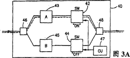
Fig. 3 A, 3B, 3C illustrate that described module comprises 1 * 1 optical switch of some parallel connections in order to another simplified embodiment of the described module that reconfigures network.
Fig. 4 illustrates another illustrated embodiment of described module, and this module comprises an optical switch matrix (optical cross connect), as a plurality of optical switches and a plurality of smooth parts that can interconnect.
The another kind of possible interconnection mode of the optical switch in the described module of Fig. 5 illustrative.
Fig. 6 illustrative a kind of composite module of the present invention, this module comprise a plurality of optical switch devices and a plurality of smooth parts, and they can be arranged with different compound modes by control device.
The detailed description of most preferred embodiment
Figure 1B has described how network configuration changes when described module is controllably constructed again.In this example, switch 16 is in bypass condition, switch 18 then in running order (representing this connection with dash line among the figure).Thus, components A and B are access in light path.In fact, how present embodiment has shown holding member A functional introduces a new part B simultaneously, exactly A and B is introduced SW2 simultaneously, and starting switch SW2 discharges switch SW 1 simultaneously then.If use enough switches fast, just can obtain almost not have the switching of instantaneous interruption with suitable delay line.Certainly, if desired, can equip all existing smooth parts 20,22 and 24 on this light path, control device 26 should all be located at operating state with two switches for this reason.
If two switches all are in bypass condition, then described module does not just influence light path fully.In other words, described module can be preloaded in prepares against upgrading in the future in the network, start this module when needs reconfigure or upgrade.
Should be pointed out that when a certain switch is in bypass condition, can be by control device 26 with the light part replacement that is attached thereto.Figure 1B shows this selection scheme, indicates light parts 21,23 and 25 with dotted line among the figure and can be connected to optical switch 16 selectively.
Fig. 2 A has described how to use 1 * 2 optical switch formation foundation module of the present invention, and the one-level of each 1 * 2 switch is single connection, and on the level relative with it two connections is arranged.This Figure illustrates the module 30 that is provided with an input and an output, this module comprises two 1 * 2 switches 32 and 34 at least.Between these two switches, be connected with one and be denoted as 36 light components A, if desired, these light parts can be denoted as 35 light part B and substitute.This can be arranged in bypass condition (figure with dash line 40 indicate) time at described switch and carry out therefore influence communication.The compound mode of the state of switch and the light parts that are connected with switch is determined by control device (CU) 38.
Fig. 2 B shown when switch 32,34 and is set at operating state and is connected in light parts between them when having been selected by control device 38, how rearrangement of optical network.Should be pointed out that it also is a kind of connected mode that can be selected by control device 38 that bypass connects (as 40 signs among Fig. 2 A).
Adopt the present embodiment of 1 * 2 switch to have more economy than the embodiment that adopts 2 * 2 switches.But the switch in the module shown in Fig. 2 A and the 2B should be by synchronously, to prevent data degradation.
Fig. 3 A, 3B and 3C have shown the another kind of optionally arrangement of switching device and light parts in the described module.In the present embodiment, described module indicates with 40, and it comprises two 1 * 1 optical switches 42 and 44, optical splitters 46, optical coupler 48, two light components A and B (being denoted as 43 and 45 respectively) and control device 47 as example.Owing to adopted new-type fast 1 * 1 switch, this layout of module can provide very fast speed, although there are some power losses in described optical splitter and the coupler.
There is shown three states of described module: light components A and B are connected respectively in the network, perhaps are connected in the network with parallel way together.It is useful being connected in parallel, and for example can use when (as in the packet switching optical-fiber network) needs being equal to of parallel fast processing to duplicate (identical copies).Another example that adopts this configuration be with it as the transstage between two levels shown in Fig. 3 A and the 3B, thereby realize that " make-before-break " do not have instantaneous interruption fully switches.In order to realize the transition of no instantaneous interruption at coupler 48 places and to avoid photo-beat effect frequently, should use suitable delay compensation line and dispersive component at the needs place.
Fig. 4 illustrates the another kind of illustrated embodiment 50 of module of the present invention.Described optical switch device constitutes optical switch matrix (n * m interconnection) 52 and 54, and they are connected to each other by an inner light path 56.Described switch matrix can follow a plurality of different light parts/non optical components (unified be denoted as 58) to connect, and ways of connecting is by control device 60 controls in order to the internal communication of controlling each switch matrix.Because at the loop of every grade of formation of described switch matrix, parts 58 can be arranged with different compound modes.Fig. 4 has shown an example configuration, and this configuration forms by insert a plurality of parts in light path; The inside connection of switch matrix indicates with dash line.Thus, can in module, add, pull down and change parts 58.If a network node comprises a such module, just can reconfigure this node easily.
Fig. 5 has shown another embodiment 60 of described module, has an optical switch 62 to connect with optical switch matrix 64 as calcaneus rete network parts (being denoted as A) in this module with connecting.Switch matrix 64 then be connected to network components B, C and D (unified be denoted as 66), they can be inserted or the dialysis light path selectively.In this example, above-mentioned parts are in order to selectively with the light add-drop multiplexer (OADM) of the channel access/disconnection light path of specific wavelength. Optical switch 62 and 64 is by a control device (CU) 68 controls.With dash line a kind of possible connected mode is shown among the figure.
Fig. 6 has described the common block configuration 70 of an example, that this module can be provided with is a plurality of (such as the different piece that is used for network node) light input end and light output end.This module comprises a plurality of optical switch devices, and wherein some is a matrix type switch 71,72 and 73, and some is the switch SW 1-SWN of other patterns.This module also comprises three optical splitters 74, three optical couplers 75 and a plurality of smooth parts/non optical component A, B...H (unified be denoted as 76).Control device 78 is responsible for arranging required configuration, just is responsible in this module coming the control switch device and forming being connected between optical splitter, coupler, parts and the switch by transmit control signal through bus.
More than describe and the embodiment of illustrated any one simplification can be at least as the part of network node, and be contained in the network usefulness in advance in order to the upgrading of this node in the future/reconfigure.Network components A, B etc. can have various function.For example, in the WDM net was realized, one or more OADM can be connected on the optical switch of module, thereby guaranteed the selection of different channels in the node is handled.Perhaps, can be made of particular network parts can be with the additional optical switching device of other one or more network componentses connections.
Should be understood that the embodiment and the combination thereof that also can propose other in the framework of notion of the present invention, they also will constitute a part of the present invention.
Claims (10)
1. module in order to any configuration/rearrangement of optical network layout, this module is to be suitable for injecting the Prefabricated block of described optical-fiber network and comprising:
-two or more optical switch devices can be connected with optical-fiber network and can be connected to each other in any way, forming serial and/or parallel the connection, and
-a plurality of network componentses can be connected with described at least one optical switch device;
Wherein said two or more optical switch device can be controlled and selectively one or more described parts be attached thereto or disconnects, their are inserted or break away from described network in the mode of not having instantaneous interruption, if so that will connect replace first to connect with second, then described switching device can be controlled and carry out described second connection after connecting disconnecting described first.
2. module as claimed in claim 1 is characterized in that described parts can be connected to described switching device, makes each described parts can or be access in described network or by bypass.
3. module as claimed in claim 1 is characterized in that being selected from following light parts and electrooptic block inventory with the described parts that described at least one optical switch device is connected: amplifier, filter, multiplexer/demultiplexer (MUX-DEMUX), light add-drop multiplexer (OADM), delay line, conversion equipment, dispersion compensation device and additional optical switching device.
4. module as claimed in claim 1 is characterized in that comprising optical switch device, and they are selected from following inventory: 1 * 2 smooth by-pass switch, 2 * 2 smooth by-pass switches and n * m optical switch matrix; In the wherein said optical switch device any can be connected with at least one described network components, and can selectively each described parts be arranged at operating state or bypass condition.
5. a reconfigurable network node comprises a kind of module in order to any configuration/rearrangement of optical network layout, and this module is to be suitable for injecting the Prefabricated block of described optical-fiber network and comprising:
Two or more optical switch devices can be connected with optical-fiber network and can be connected to each other in any way, forming serial and/or parallel the connection, and a plurality of network components, can be connected with described at least one optical switch device;
Wherein said two or more optical switch device can be controlled and selectively one or more described parts be attached thereto or disconnects, their are inserted or break away from described network in the mode of not having instantaneous interruption, if so that will connect replace first to connect with second, then described switching device can be controlled and carry out described second connection after connecting disconnecting described first.
6. module as claimed in claim 1, described module has that some light input ends are used for input optical signal and some light output ends are used to export light signal, described module comprises: control unit, more than first switching device by described control unit control, more than second optical element and more than the 3rd optical beam-splitter and coupler; Can be connected with each described more than first switching device or disconnect selectively by described control unit control, each described more than second optical element, can be connected with each described more than first switching device or disconnect selectively with coupler by the control of described control unit, each described more than the 3rd optical beam-splitter, wherein each described light input end and each described light output end can be controlled and can be connected with coupler with each described more than the 3rd optical beam-splitter selectively or disconnect.
7. a Prefabricated block that is suitable for injecting optical-fiber network by use disposes/method of rearrangement of optical network, and described module comprises:
Two or more optical switch devices can be connected with optical-fiber network and can be connected to each other in any way, forming serial and/or parallel the connection, and
A plurality of network componentses can be connected with described at least one optical switch device;
Wherein said two or more optical switch device can be controlled and selectively one or more described parts be attached thereto or disconnects, their are inserted or break away from described network in the mode of not having instantaneous interruption, if replace first to connect so that will connect with second, then described switching device can be controlled and carry out described second connection after connecting disconnecting described first
And described method comprises:
Described module is inserted the part of described optical-fiber network;
Selection of configuration as requested will be access in the network components of one or more described modules of described network, and remaining network components is considered as non-selected components;
, connect so that non-selected components is arranged at described bypass condition and selected components is arranged at operating state by controlling described at least one optical switch device thereby in described module, form according to the desired mode that is configured to not have instantaneous interruption.
8. method as claimed in claim 7 is characterized in that providing the described step that described module is inserted described network when needs are upgraded.
9. method as claimed in claim 7 is characterized in that the described step that described module is inserted described network carries out in advance when described network is set up.
10. method as claimed in claim 9 is characterized in that the described step that described module is inserted described network comprises: described module is installed in advance, thereby makes described node reconfigurable in network node.
Applications Claiming Priority (2)
| Application Number | Priority Date | Filing Date | Title |
|---|---|---|---|
| IL140207A IL140207A (en) | 2000-12-10 | 2000-12-10 | Module and method for reconfiguring optical networks |
| IL140207 | 2000-12-10 |
Publications (2)
| Publication Number | Publication Date |
|---|---|
| CN1360416A CN1360416A (en) | 2002-07-24 |
| CN1263246C true CN1263246C (en) | 2006-07-05 |
Family
ID=11074908
Family Applications (1)
| Application Number | Title | Priority Date | Filing Date |
|---|---|---|---|
| CNB011438487A Expired - Fee Related CN1263246C (en) | 2000-12-10 | 2001-12-10 | Module and method for rearrangement of optical network |
Country Status (9)
| Country | Link |
|---|---|
| US (1) | US20020071151A1 (en) |
| EP (1) | EP1213944A3 (en) |
| KR (1) | KR100798979B1 (en) |
| CN (1) | CN1263246C (en) |
| AU (1) | AU783414B2 (en) |
| BR (1) | BR0105914A (en) |
| CA (1) | CA2361854A1 (en) |
| EA (1) | EA004425B1 (en) |
| IL (1) | IL140207A (en) |
Families Citing this family (12)
| Publication number | Priority date | Publication date | Assignee | Title |
|---|---|---|---|---|
| IL146822A0 (en) | 2001-11-29 | 2002-07-25 | Lightscape Networks Ltd | Method and device for expanding communication networks |
| JP2004317717A (en) * | 2003-04-15 | 2004-11-11 | Canon Inc | Reconfigurable photoelectric fusion circuit |
| US7266294B2 (en) | 2003-12-02 | 2007-09-04 | Fujitsu Limited | Coupler-based optical cross-connect |
| EP1896886A1 (en) * | 2005-06-30 | 2008-03-12 | Pirelli & C. S.p.A. | Method and system for hitless tunable optical processing |
| JP2007096362A (en) * | 2005-09-05 | 2007-04-12 | Pacific Ind Co Ltd | Optical lan terminal device and optical lan system |
| US8023825B2 (en) | 2006-04-04 | 2011-09-20 | Cisco Technology, Inc. | Optical switching architectures for nodes in WDM mesh and ring networks |
| US9641275B2 (en) * | 2011-06-17 | 2017-05-02 | Tyco Electronics Subsea Communications Llc | Symmetric optical multiplexing node |
| WO2013137870A1 (en) * | 2012-03-14 | 2013-09-19 | Hewlett-Packard Development Company, L.P. | Replaceable modular optical connection assembly |
| US20140314417A1 (en) * | 2012-04-12 | 2014-10-23 | Kevin B. Leigh | Reconfiguration of an optical connection infrastructure |
| EP3272131B1 (en) | 2015-08-14 | 2023-10-04 | Hewlett Packard Enterprise Development LP | Optical signals |
| CN111262622A (en) * | 2020-01-14 | 2020-06-09 | 国家计算机网络与信息安全管理中心 | Optical fiber line bypass protection device and method |
| US11256032B1 (en) * | 2020-12-15 | 2022-02-22 | Dspace Gmbh | Programmable fiber-optic delay line |
Family Cites Families (12)
| Publication number | Priority date | Publication date | Assignee | Title |
|---|---|---|---|---|
| US4927225A (en) * | 1989-05-30 | 1990-05-22 | Finisar Corporation | 2×2 Optical bypass switch |
| CN1251520C (en) * | 1994-09-14 | 2006-04-12 | 西门子公司 | Tree-structured optical 1XN and NXN switch matrices |
| US5726788A (en) * | 1996-09-30 | 1998-03-10 | Mci Corporation | Dynamically reconfigurable optical interface device using an optically switched backplane |
| KR100221528B1 (en) * | 1996-12-16 | 1999-09-15 | 정선종 | Test access method of synchronous transmission network |
| US6188509B1 (en) * | 1997-01-05 | 2001-02-13 | Korea Advanced Institute Science And Technology | Simple bidirectional add/drop amplifier module based on a single multiplexer |
| US6035080A (en) * | 1997-06-20 | 2000-03-07 | Henry; Charles Howard | Reconfigurable add-drop multiplexer for optical communications systems |
| KR100237365B1 (en) * | 1997-10-22 | 2000-01-15 | 이계철 | Residential b-tn system for b-isdn |
| US6014480A (en) * | 1997-11-21 | 2000-01-11 | Hewlett-Packard Company | Optical energy selector apparatus and method |
| US6327059B1 (en) * | 1998-06-17 | 2001-12-04 | Lucent Technologies, Inc. | Optical signal processing modules |
| US6519064B1 (en) * | 1998-06-19 | 2003-02-11 | Lucent Technologies Inc. | Scalable add/drop architecture for lightwave communication system |
| FI106683B (en) * | 1998-11-10 | 2001-03-15 | Nokia Networks Oy | Certification in optical communication system |
| KR100299970B1 (en) * | 1999-03-31 | 2001-10-29 | 윤종용 | Apparatus for coolling of projection TV |
-
2000
- 2000-12-10 IL IL140207A patent/IL140207A/en not_active IP Right Cessation
-
2001
- 2001-11-13 AU AU89412/01A patent/AU783414B2/en not_active Ceased
- 2001-11-13 CA CA002361854A patent/CA2361854A1/en not_active Abandoned
- 2001-11-20 EP EP01204433A patent/EP1213944A3/en not_active Withdrawn
- 2001-11-23 EA EA200101129A patent/EA004425B1/en not_active IP Right Cessation
- 2001-11-30 KR KR1020010075296A patent/KR100798979B1/en not_active IP Right Cessation
- 2001-12-07 BR BR0105914-9A patent/BR0105914A/en not_active IP Right Cessation
- 2001-12-10 CN CNB011438487A patent/CN1263246C/en not_active Expired - Fee Related
- 2001-12-10 US US10/006,716 patent/US20020071151A1/en not_active Abandoned
Also Published As
| Publication number | Publication date |
|---|---|
| EA200101129A2 (en) | 2002-06-27 |
| IL140207A (en) | 2007-09-20 |
| BR0105914A (en) | 2002-08-06 |
| KR20020046931A (en) | 2002-06-21 |
| EP1213944A2 (en) | 2002-06-12 |
| IL140207A0 (en) | 2002-02-10 |
| CA2361854A1 (en) | 2002-06-10 |
| US20020071151A1 (en) | 2002-06-13 |
| EA004425B1 (en) | 2004-04-29 |
| EP1213944A3 (en) | 2007-06-06 |
| AU783414B2 (en) | 2005-10-27 |
| EA200101129A3 (en) | 2002-08-29 |
| KR100798979B1 (en) | 2008-01-28 |
| CN1360416A (en) | 2002-07-24 |
| AU8941201A (en) | 2002-06-13 |
Similar Documents
| Publication | Publication Date | Title |
|---|---|---|
| CN1263246C (en) | Module and method for rearrangement of optical network | |
| US9048974B2 (en) | Methods for expanding cross-connect capacity in a ROADM optical network | |
| EP2692143B1 (en) | Adaptive waveguide optical switching system and method | |
| JP5470379B2 (en) | Device for switching optical signals | |
| US20100124391A1 (en) | Growable multi-degree ROADM | |
| EP1030481B1 (en) | A cross-connect device and a method for switching based on space switching and grouping of channels | |
| JP2000508138A (en) | Chromatic dispersion compensation node | |
| WO2013115905A1 (en) | Contentionless add-drop multiplexer | |
| US7110638B2 (en) | Reconfigurable optical node with distributed spectral filtering | |
| US20010024305A1 (en) | Optical node device and signal switching and connection method | |
| US7221873B1 (en) | Network nodes with optical add/drop modules | |
| CN1214551C (en) | Optical fiber looped network system and optical add-drop multiplexing module and upgrade expanding method thereof | |
| AU760925B2 (en) | Add-drop-multiplexer and optical wavelength division multiplex transmission system | |
| US20050276605A1 (en) | Method of upgrading an optical transmission network, an optical transmission network, and associated optical transmission nodes | |
| CN1630377A (en) | A hardware platform for transmission apparatus | |
| CN1295394A (en) | Optical cross connection node for crossing between fiber link and wavelength groups | |
| US7266294B2 (en) | Coupler-based optical cross-connect | |
| AU1498800A (en) | Reconfigurable optical filtering apparatus and a drop-and- insert multiplexer incorporating such apparatus | |
| KR100431204B1 (en) | A Large scale Optical Cross Connect Switching System using Optical Switch fabric Modules | |
| CN1894880A (en) | Add-drop device and cross-connect device for wavelength multiplex signals | |
| Collings | Physical layer components, architectures and trends for agile photonic layer mesh networking | |
| CN1885755A (en) | OADM site | |
| Yang | Understanding wavelength cross-connects and their benefits throughout the network | |
| Queller | Improving wireline infrastructure performance incrementally with intelligent photonic switching systems |
Legal Events
| Date | Code | Title | Description |
|---|---|---|---|
| C06 | Publication | ||
| PB01 | Publication | ||
| C10 | Entry into substantive examination | ||
| SE01 | Entry into force of request for substantive examination | ||
| C14 | Grant of patent or utility model | ||
| GR01 | Patent grant | ||
| C17 | Cessation of patent right | ||
| CF01 | Termination of patent right due to non-payment of annual fee |
Granted publication date: 20060705 Termination date: 20121210 |