CN1253713C - Ultrasonic flaw detection method on cylinder surface - Google Patents
Ultrasonic flaw detection method on cylinder surface Download PDFInfo
- Publication number
- CN1253713C CN1253713C CNB031368867A CN03136886A CN1253713C CN 1253713 C CN1253713 C CN 1253713C CN B031368867 A CNB031368867 A CN B031368867A CN 03136886 A CN03136886 A CN 03136886A CN 1253713 C CN1253713 C CN 1253713C
- Authority
- CN
- China
- Prior art keywords
- surface wave
- probe
- grinding
- drum
- ultrasonic
- Prior art date
- Legal status (The legal status is an assumption and is not a legal conclusion. Google has not performed a legal analysis and makes no representation as to the accuracy of the status listed.)
- Expired - Fee Related
Links
Images


Classifications
-
- G—PHYSICS
- G01—MEASURING; TESTING
- G01N—INVESTIGATING OR ANALYSING MATERIALS BY DETERMINING THEIR CHEMICAL OR PHYSICAL PROPERTIES
- G01N29/00—Investigating or analysing materials by the use of ultrasonic, sonic or infrasonic waves; Visualisation of the interior of objects by transmitting ultrasonic or sonic waves through the object
- G01N29/22—Details, e.g. general constructional or apparatus details
- G01N29/24—Probes
- G01N29/2487—Directing probes, e.g. angle probes
-
- G—PHYSICS
- G01—MEASURING; TESTING
- G01N—INVESTIGATING OR ANALYSING MATERIALS BY DETERMINING THEIR CHEMICAL OR PHYSICAL PROPERTIES
- G01N29/00—Investigating or analysing materials by the use of ultrasonic, sonic or infrasonic waves; Visualisation of the interior of objects by transmitting ultrasonic or sonic waves through the object
- G01N29/04—Analysing solids
-
- B—PERFORMING OPERATIONS; TRANSPORTING
- B24—GRINDING; POLISHING
- B24B—MACHINES, DEVICES, OR PROCESSES FOR GRINDING OR POLISHING; DRESSING OR CONDITIONING OF ABRADING SURFACES; FEEDING OF GRINDING, POLISHING, OR LAPPING AGENTS
- B24B27/00—Other grinding machines or devices
- B24B27/033—Other grinding machines or devices for grinding a surface for cleaning purposes, e.g. for descaling or for grinding off flaws in the surface
-
- B—PERFORMING OPERATIONS; TRANSPORTING
- B24—GRINDING; POLISHING
- B24B—MACHINES, DEVICES, OR PROCESSES FOR GRINDING OR POLISHING; DRESSING OR CONDITIONING OF ABRADING SURFACES; FEEDING OF GRINDING, POLISHING, OR LAPPING AGENTS
- B24B49/00—Measuring or gauging equipment for controlling the feed movement of the grinding tool or work; Arrangements of indicating or measuring equipment, e.g. for indicating the start of the grinding operation
- B24B49/10—Measuring or gauging equipment for controlling the feed movement of the grinding tool or work; Arrangements of indicating or measuring equipment, e.g. for indicating the start of the grinding operation involving electrical means
-
- B—PERFORMING OPERATIONS; TRANSPORTING
- B24—GRINDING; POLISHING
- B24B—MACHINES, DEVICES, OR PROCESSES FOR GRINDING OR POLISHING; DRESSING OR CONDITIONING OF ABRADING SURFACES; FEEDING OF GRINDING, POLISHING, OR LAPPING AGENTS
- B24B49/00—Measuring or gauging equipment for controlling the feed movement of the grinding tool or work; Arrangements of indicating or measuring equipment, e.g. for indicating the start of the grinding operation
- B24B49/12—Measuring or gauging equipment for controlling the feed movement of the grinding tool or work; Arrangements of indicating or measuring equipment, e.g. for indicating the start of the grinding operation involving optical means
-
- B—PERFORMING OPERATIONS; TRANSPORTING
- B24—GRINDING; POLISHING
- B24B—MACHINES, DEVICES, OR PROCESSES FOR GRINDING OR POLISHING; DRESSING OR CONDITIONING OF ABRADING SURFACES; FEEDING OF GRINDING, POLISHING, OR LAPPING AGENTS
- B24B5/00—Machines or devices designed for grinding surfaces of revolution on work, including those which also grind adjacent plane surfaces; Accessories therefor
- B24B5/36—Single-purpose machines or devices
- B24B5/363—Single-purpose machines or devices for grinding surfaces of revolution in situ
-
- B—PERFORMING OPERATIONS; TRANSPORTING
- B24—GRINDING; POLISHING
- B24B—MACHINES, DEVICES, OR PROCESSES FOR GRINDING OR POLISHING; DRESSING OR CONDITIONING OF ABRADING SURFACES; FEEDING OF GRINDING, POLISHING, OR LAPPING AGENTS
- B24B5/00—Machines or devices designed for grinding surfaces of revolution on work, including those which also grind adjacent plane surfaces; Accessories therefor
- B24B5/36—Single-purpose machines or devices
- B24B5/37—Single-purpose machines or devices for grinding rolls, e.g. barrel-shaped rolls
-
- G—PHYSICS
- G01—MEASURING; TESTING
- G01N—INVESTIGATING OR ANALYSING MATERIALS BY DETERMINING THEIR CHEMICAL OR PHYSICAL PROPERTIES
- G01N29/00—Investigating or analysing materials by the use of ultrasonic, sonic or infrasonic waves; Visualisation of the interior of objects by transmitting ultrasonic or sonic waves through the object
- G01N29/04—Analysing solids
- G01N29/041—Analysing solids on the surface of the material, e.g. using Lamb, Rayleigh or shear waves
-
- G—PHYSICS
- G01—MEASURING; TESTING
- G01N—INVESTIGATING OR ANALYSING MATERIALS BY DETERMINING THEIR CHEMICAL OR PHYSICAL PROPERTIES
- G01N29/00—Investigating or analysing materials by the use of ultrasonic, sonic or infrasonic waves; Visualisation of the interior of objects by transmitting ultrasonic or sonic waves through the object
- G01N29/22—Details, e.g. general constructional or apparatus details
- G01N29/228—Details, e.g. general constructional or apparatus details related to high temperature conditions
-
- G—PHYSICS
- G01—MEASURING; TESTING
- G01N—INVESTIGATING OR ANALYSING MATERIALS BY DETERMINING THEIR CHEMICAL OR PHYSICAL PROPERTIES
- G01N29/00—Investigating or analysing materials by the use of ultrasonic, sonic or infrasonic waves; Visualisation of the interior of objects by transmitting ultrasonic or sonic waves through the object
- G01N29/22—Details, e.g. general constructional or apparatus details
- G01N29/24—Probes
- G01N29/2437—Piezoelectric probes
- G01N29/245—Ceramic probes, e.g. lead zirconate titanate [PZT] probes
-
- G—PHYSICS
- G01—MEASURING; TESTING
- G01N—INVESTIGATING OR ANALYSING MATERIALS BY DETERMINING THEIR CHEMICAL OR PHYSICAL PROPERTIES
- G01N29/00—Investigating or analysing materials by the use of ultrasonic, sonic or infrasonic waves; Visualisation of the interior of objects by transmitting ultrasonic or sonic waves through the object
- G01N29/22—Details, e.g. general constructional or apparatus details
- G01N29/26—Arrangements for orientation or scanning by relative movement of the head and the sensor
-
- G—PHYSICS
- G01—MEASURING; TESTING
- G01N—INVESTIGATING OR ANALYSING MATERIALS BY DETERMINING THEIR CHEMICAL OR PHYSICAL PROPERTIES
- G01N29/00—Investigating or analysing materials by the use of ultrasonic, sonic or infrasonic waves; Visualisation of the interior of objects by transmitting ultrasonic or sonic waves through the object
- G01N29/22—Details, e.g. general constructional or apparatus details
- G01N29/28—Details, e.g. general constructional or apparatus details providing acoustic coupling, e.g. water
-
- G—PHYSICS
- G01—MEASURING; TESTING
- G01N—INVESTIGATING OR ANALYSING MATERIALS BY DETERMINING THEIR CHEMICAL OR PHYSICAL PROPERTIES
- G01N29/00—Investigating or analysing materials by the use of ultrasonic, sonic or infrasonic waves; Visualisation of the interior of objects by transmitting ultrasonic or sonic waves through the object
- G01N29/36—Detecting the response signal, e.g. electronic circuits specially adapted therefor
- G01N29/40—Detecting the response signal, e.g. electronic circuits specially adapted therefor by amplitude filtering, e.g. by applying a threshold or by gain control
-
- G—PHYSICS
- G01—MEASURING; TESTING
- G01N—INVESTIGATING OR ANALYSING MATERIALS BY DETERMINING THEIR CHEMICAL OR PHYSICAL PROPERTIES
- G01N29/00—Investigating or analysing materials by the use of ultrasonic, sonic or infrasonic waves; Visualisation of the interior of objects by transmitting ultrasonic or sonic waves through the object
- G01N29/36—Detecting the response signal, e.g. electronic circuits specially adapted therefor
- G01N29/42—Detecting the response signal, e.g. electronic circuits specially adapted therefor by frequency filtering or by tuning to resonant frequency
-
- G—PHYSICS
- G01—MEASURING; TESTING
- G01N—INVESTIGATING OR ANALYSING MATERIALS BY DETERMINING THEIR CHEMICAL OR PHYSICAL PROPERTIES
- G01N2291/00—Indexing codes associated with group G01N29/00
- G01N2291/04—Wave modes and trajectories
- G01N2291/042—Wave modes
- G01N2291/0421—Longitudinal waves
-
- G—PHYSICS
- G01—MEASURING; TESTING
- G01N—INVESTIGATING OR ANALYSING MATERIALS BY DETERMINING THEIR CHEMICAL OR PHYSICAL PROPERTIES
- G01N2291/00—Indexing codes associated with group G01N29/00
- G01N2291/04—Wave modes and trajectories
- G01N2291/042—Wave modes
- G01N2291/0423—Surface waves, e.g. Rayleigh waves, Love waves
-
- G—PHYSICS
- G01—MEASURING; TESTING
- G01N—INVESTIGATING OR ANALYSING MATERIALS BY DETERMINING THEIR CHEMICAL OR PHYSICAL PROPERTIES
- G01N2291/00—Indexing codes associated with group G01N29/00
- G01N2291/04—Wave modes and trajectories
- G01N2291/057—Angular incidence, parallel to surface propagation
-
- G—PHYSICS
- G01—MEASURING; TESTING
- G01N—INVESTIGATING OR ANALYSING MATERIALS BY DETERMINING THEIR CHEMICAL OR PHYSICAL PROPERTIES
- G01N2291/00—Indexing codes associated with group G01N29/00
- G01N2291/26—Scanned objects
- G01N2291/263—Surfaces
- G01N2291/2634—Surfaces cylindrical from outside
Landscapes
- Physics & Mathematics (AREA)
- Chemical & Material Sciences (AREA)
- General Health & Medical Sciences (AREA)
- Health & Medical Sciences (AREA)
- Life Sciences & Earth Sciences (AREA)
- Analytical Chemistry (AREA)
- Biochemistry (AREA)
- General Physics & Mathematics (AREA)
- Immunology (AREA)
- Pathology (AREA)
- Engineering & Computer Science (AREA)
- Mechanical Engineering (AREA)
- Acoustics & Sound (AREA)
- Ceramic Engineering (AREA)
- Investigating Or Analyzing Materials By The Use Of Ultrasonic Waves (AREA)
Abstract
本发明提供一种金属圆柱体的超声波探伤方法,它是在旋转的金属圆柱体表面通过接触介质接触表面波探头,从该表面波探头对金属圆柱体传播表面波,同时通过接收来自金属圆柱体表面或紧挨表面下存在的缺陷的反射波,检出该缺陷的金属圆柱体超声波探伤方法,其特征为:使前述表面波探头发送接收的表面波脉冲的脉宽小于在前述金属圆柱体传输的表面波波长的2.5倍。
The invention provides an ultrasonic flaw detection method of a metal cylinder, which is to contact a surface wave probe on the surface of a rotating metal cylinder through a contact medium, propagate a surface wave from the surface wave probe to the metal cylinder, and simultaneously receive a wave from the metal cylinder A metal cylinder ultrasonic flaw detection method for detecting the defect existing on the surface or immediately below the surface, characterized in that the pulse width of the surface wave pulse transmitted and received by the surface wave probe is smaller than that transmitted by the metal cylinder 2.5 times the wavelength of surface waves.
Description
本申请是申请号为98802950.2的申请的分案申请,该母案的申请日为1998年10月29日,在先申请为JP97-300409,在先申请日为1997年10月31日。This application is a divisional application of the application number 98802950.2, the filing date of the parent application is October 29, 1998, and the earlier application is JP97-300409, and the earlier application date is October 31, 1997.
技术领域technical field
本发明涉及用表面波检出辗压滚筒或辗压机等的金属圆柱体,尤其是承受由辗压在表面上产生热的、机械的损伤的高速工具钢构成的辗压用高速工具钢滚筒表面或紧挨表面下存在的裂纹等缺陷时使用的合适的圆柱体表面超声波探伤方法及其探伤装置,以及利用它们对滚筒的磨削方法。The present invention relates to the use of surface waves to detect metal cylinders such as rolling rollers or rolling machines, especially high-speed tool steel rollers for rolling that are made of high-speed tool steel that produces thermal and mechanical damage on the surface. Appropriate ultrasonic flaw detection methods and flaw detection devices for cylinder surfaces used when defects such as cracks exist on the surface or immediately below the surface, and the grinding method of the cylinder using them.
背景技术Background technique
金属板在热轧中使用的辗压滚筒承受由辗压在表面上产生的热的、机械的损伤。以下用图20详细说明在热加工辗压用的高速工具钢滚筒制成的前段工作辊(以下称为加工前段工作台用高速钢滚筒)表面的热的、机械的损伤。热损伤起因于在加工台前段被辗压材料处于高温,在与滚筒100表面垂直方向产生称为热裂纹的深的1次裂纹K。机械损伤是由与支承辊一起转动产生剪应力引起的,以前述热裂纹K作为起点,2次裂纹L在与滚筒表面大体平行的方向上生成。同时这些裂纹许多个连接在一起,在滚筒表面上形成微小缺陷M。因为该微小缺陷M一旦复制在被辗压材料上,形成被辗压材料的表面缺陷,所以从表面到一定的深度(以下称为一定量),例如用砂轮磨削除去后,在再辗压中使用滚筒,磨削后,如特开平4-276547所示,进行用表面波的超声波探伤(称为表面波探伤)。Rolling rolls used in hot rolling of sheet metal are subjected to thermal and mechanical damage caused by rolling on the surface. The thermal and mechanical damage to the surface of the front-end work roll (hereinafter referred to as the high-speed steel roll for the front-stage workbench) made of the high-speed tool steel roll for hot-working rolling will be described in detail below with reference to FIG. 20 . Thermal damage is caused by the fact that the material to be rolled at the front of the processing table is at a high temperature, and deep primary cracks K called thermal cracks are generated in a direction perpendicular to the surface of the drum 100 . The mechanical damage is caused by the shear stress generated by the rotation together with the back-up roll, and the secondary crack L is formed in a direction substantially parallel to the surface of the roll starting from the above-mentioned thermal crack K. At the same time, many of these cracks are connected together to form minute defects M on the surface of the drum. Because once the tiny defect M is copied on the material to be rolled, it will form a surface defect of the material to be rolled, so from the surface to a certain depth (hereinafter referred to as a certain amount), for example, after being removed by grinding with a grinding wheel, it will be rolled again. After grinding using a roller, as shown in JP-A-4-276547, ultrasonic flaw detection using surface waves (referred to as surface wave flaw detection) is carried out.
具体地讲,在旋转的滚筒表面通过水等接触介质膜接触表面波探头(检测头),在从该表面波探头向滚筒旋转方向相反的方向传播表面波的同时要除去滚筒表面中传播表面波部分的接触介质膜,以便检出在滚筒表面或紧挨表面下存在的缺陷。如果用该表面波探伤法检出缺陷,则进行追加的磨削。Specifically, the surface of the rotating drum is contacted with a surface wave probe (detection head) through a contact medium film such as water, and the surface wave propagating from the surface wave probe to the direction opposite to the drum rotation direction is removed. Partial contact with the dielectric film in order to detect defects existing on or immediately below the surface of the drum. If a defect is detected by the surface wave flaw detection method, additional grinding is performed.
作为应用特开平4-276547的探伤法的装置,有特开平7-294493中展示的超声波探伤装置。该超声波探伤装置具有以下部件,即:使预定的检查表面缺陷等的圆筒状或圆柱状被检材料沿着其圆周方向旋转的旋转手段,用超声波检出缺陷等的超声波探头,用于使该探头对被检材料上方的被检材料表面维持一定间隔的定位部,把形成超声波传播媒体的水等的介质液提供到探头和被检材料之间的给水装置。前述定位部具有从探头下方突出,而且与被检材料表面圆滑地接触的仿形部。该仿形部通过与旋转中的被检材料的接触保持定位部对被检材料的间隔一定。此外前述定位部在探头近旁设置前述给水装置。该给水装置具有可能暂时贮存向探头近旁导出的介质液的收容部。该收容部位于探头近旁,在底部具有多个放水口,同时在上部具有向外部贯通的排气孔。这样安排前述多个放水口的各个口,以便通过被检材料的旋转,在探头对被检材料表面扫描时,在其进行方向的前方,与前述周方向交叉配置,从扫描中探头的前方把收容部内的介质水向探头和被检材料表面之间放水。As an apparatus to which the flaw detection method of JP-A-4-276547 is applied, there is an ultrasonic flaw-detection apparatus disclosed in JP-A-7-294493. The ultrasonic flaw detection device has the following components, that is, a rotating means for rotating a cylindrical or columnar test material to be inspected for surface defects and the like along its circumferential direction, an ultrasonic probe for detecting defects and the like with ultrasonic waves, The probe maintains a fixed distance from the surface of the test material above the test material, and supplies a medium liquid such as water that forms an ultrasonic propagation medium to a water supply device between the probe and the test material. The aforementioned positioning part has a profiled part protruding from the bottom of the probe and smoothly contacting the surface of the material to be tested. The profiling portion maintains a constant distance between the positioning portion and the inspected material by contacting the rotating inspected material. In addition, the positioning part is provided with the water supply device near the probe. This water supply device has a storage part that can temporarily store the medium liquid that is led out to the vicinity of the probe. The accommodating part is located near the probe, has a plurality of water outlets at the bottom, and has an exhaust hole penetrating to the outside at the top. In this way, each mouth of the aforementioned plurality of water outlets is arranged so that through the rotation of the material to be tested, when the probe scans the surface of the material to be tested, it is arranged in front of the direction in which it is carried out, and is arranged crosswise with the aforementioned circumferential direction. The medium water in the receiving part releases water between the probe and the surface of the material to be inspected.
然而,如果把前述的特开平4-276547的探伤法尤其是用于检测加工前段工作台用的高速钢滚筒的表面或紧挨表面下存在的缺陷,则最近查明存在如下所述的大问题。However, if the flaw detection method of the aforementioned Japanese Patent Laid-Open No. 4-276547 is used to detect defects existing on the surface or immediately below the surface of the high-speed steel roller used for the workbench in the front stage of processing, it has recently been found that there are major problems as follows .
即:由于图20所示的微小缺陷M一定产生2次裂纹L,所以为了防止该微小缺陷M的发生通过磨削只除去2次裂纹L便行了。但是采用传统的超声波探伤方法,完全除去2次裂纹L后,也观测到出现大振幅反射波的现象,如果磨削到完全不出现该反射波,则因为要完全磨掉直到不要除去的1次裂纹K的残存部分为止,所以滚筒的单耗变差。That is, since the minute defects M shown in FIG. 20 always generate secondary cracks L, it is sufficient to remove only the secondary cracks L by grinding in order to prevent the occurrence of the minute defects M. However, using the traditional ultrasonic flaw detection method, after the second crack L is completely removed, the phenomenon of large-amplitude reflection waves is also observed. If the reflection wave does not appear at all after grinding, it is because the first time that is not to be removed must be completely ground. The remaining part of the crack K, so the unit consumption of the drum deteriorates.
这是由于用表面波的超声波探伤法对于滚筒表面上的垂直缺陷敏感性高,即使完全除去2次裂纹L也能检出1次裂纹K的残存部分。由于该1次裂纹K的残存部分深度颇小,所以来自各个1次裂纹K的残存部分的反射波振幅变微小,但是1次裂纹K的残存部分在滚筒表面无数地存在,用表面波的超声波探伤,表面波的传播路径也无数地存在。在用表面波对具有这种无数微小反射体的被检材料(在这里指滚筒)探伤时,如果令表面波的波长为入,则如图21所示,一定存在离表面波探头10的距离差为λ/2的微小反射体的组合。图21举例示出该微小反射体的组合,而微小反射体K1~K4符合这种组合。This is because the ultrasonic flaw detection method using surface waves is highly sensitive to vertical flaws on the drum surface, and even if the secondary cracks L are completely removed, the remaining portion of the primary crack K can be detected. Since the depth of the remaining portion of the primary crack K is quite small, the amplitude of the reflected wave from the remaining portion of each primary crack K becomes small, but the remaining portion of the primary crack K exists innumerably on the surface of the drum, and the surface waves In flaw detection, there are countless propagation paths of surface waves. When surface waves are used to detect the flaws of the tested material (here, the drum) with such countless tiny reflectors, if the wavelength of the surface waves is λ, then as shown in Figure 21, there must be a distance from the surface wave probe 10 A combination of tiny reflectors with a difference of λ/2. FIG. 21 exemplifies the combination of the microreflectors, and the microreflectors K1 to K4 correspond to this combination.
如果如传统方式用脉宽为表面波波长5倍以上的狭带脉冲对存在这些微小反射体K1~K4的区域探伤,则因为脉宽长,如图22所示,微小反射波以等相位叠加干涉,振幅增大,产生好像存在大缺陷那样的反射波。即:对于热加工辗压前段工作台用高速钢滚筒利用表面波的超声波探伤时,因为用脉宽为表面波的波长5倍以上的狭带脉冲探伤,所以过大地检出从1次裂纹K的反射波振幅。其结果,进行磨削直到来自1次裂纹K的反射波振幅比预定值小为止。结果是因为几乎完全除去1次裂纹K,所以磨削量过大,滚筒的单耗变差。If the narrow-band pulse whose pulse width is more than 5 times the wavelength of the surface wave is used to detect flaws in the area where these tiny reflectors K1-K4 exist, as shown in Figure 22, because of the long pulse width, the tiny reflected waves are superimposed with equal phases Interference, the amplitude increases, and a reflected wave appears as if there is a large defect. That is: when using ultrasonic flaw detection of surface waves for the high-speed steel rollers used in the front-end workbench of hot-working rolling, because the narrow-band pulse flaw detection with a pulse width that is more than 5 times the wavelength of the surface waves is used, the primary crack K is too large to be detected. the amplitude of the reflected wave. As a result, grinding is performed until the amplitude of the reflected wave from the primary crack K becomes smaller than a predetermined value. As a result, since the primary crack K was almost completely removed, the amount of grinding was too large, and the unit consumption of the drum was poor.
也考虑把缺陷检出设定的阀值提高到不会对1次裂纹K过检出的程度。然而如果提高该阈值,则由于会引起缺陷检出能力下降,所以存在单独存在的裂纹(由辗压事故产生的)等应检出的缺陷漏检的危险性。It is also considered to increase the threshold value of the defect detection setting to the extent that the primary crack K will not be over-detected. However, if the threshold value is increased, the defect detection capability will decrease, so there is a risk that defects that should be detected such as cracks that exist alone (generated by rolling accidents) will not be detected.
以上说明的超声波探伤的问题不仅在辗压滚筒等1次裂纹内存在,而且在滚筒等一般金属圆柱体内,在结晶组织粗、晶粒边界产生散射波的情况下,如果用传统的狭带脉冲进行探伤,则由于与已经说明的现象相同的机理,产生高的噪声,存在同样的问题。The problems of ultrasonic flaw detection explained above not only exist in primary cracks such as rolling rollers, but also in general metal cylinders such as rollers. In flaw detection, due to the same mechanism as the already explained phenomenon, high noise is generated and the same problem exists.
由辗压产生的热的、机械的损伤深度则依辗压金属板的长度及辗压速度、滚筒的冷却条件,材质(即使是分类为同一材质的滚筒,也因制造方法的不同而有材质细微差异)等而有很大差异。因此,如果要以一定量磨研除去它,则产生如下的问题。The depth of thermal and mechanical damage caused by rolling depends on the length of the rolled metal plate, the rolling speed, the cooling conditions of the roller, and the material (even if the rollers are classified as the same material, there are different materials due to different manufacturing methods. small differences) and so on. Therefore, if it is to be ground and removed by a certain amount, the following problems arise.
①在热的、机械的负荷小,热的机械的损伤深度小的情况下,磨掉(过磨削)滚筒表面直到无损伤部分,磨削量大,滚筒的单耗变差。① In the case of small thermal and mechanical loads and small thermal mechanical damage depth, the surface of the drum is ground (over-grinded) until there is no damage, the grinding amount is large, and the unit consumption of the drum becomes poor.
②在热的、机械的负荷大,热的、机械的损伤深度大的情况下,一定量磨削后也残存损伤,由于在探伤时检出缺陷,所以必须追加磨削。可是热的、机械的损伤究竟残存到什么程度并不清楚,所以不能做到使追加的磨削量与最初的磨削量相同程度,大体上过削(过磨削),磨削量多,滚筒的单耗变差。② When the thermal and mechanical load is large, and the thermal and mechanical damage depth is large, the damage will remain after a certain amount of grinding. Since defects are detected during flaw detection, additional grinding is necessary. However, it is unclear to what extent the thermal and mechanical damage remains, so it is impossible to make the additional grinding amount equal to the initial grinding amount. The unit consumption of the drum becomes worse.
③仅仅考虑上述过磨削所需时间已使滚筒的磨削时间变长,滚筒磨削效率下降。③ Only considering the time required for the above-mentioned over-grinding has made the grinding time of the drum longer, and the grinding efficiency of the drum has decreased.
此外,特开平7-294493展示的超声波探伤装置完全没有考虑被检材料的转速和必需的介质液量之间的关系,而相应于被检材料的转速,在被检材料上打滑,从探头和被检材料表面之间逃逸的介质液量变化,例如,如果被检材料的转速增加,则从探头和被检材料之间逃逸的介质液量增加,探头和被检材料表面之间的介质液量不足,超声波对被检材料的传递不佳,不能检出表面缺陷。相反,如果滚筒的转速变小,过剩的介质液在探头前方流出,因此表面波衰减,也不能检出表面缺陷。In addition, the ultrasonic flaw detection device disclosed in Japanese Patent Laid-Open No. 7-294493 does not consider the relationship between the rotational speed of the tested material and the necessary medium liquid volume at all, but corresponding to the rotational speed of the tested material, slipping on the tested material, from the probe and Changes in the amount of medium liquid escaping between the surface of the material to be tested, for example, if the rotational speed of the material to be tested increases, the amount of medium liquid escaping from between the probe and the material to be tested increases, and the medium liquid between the probe and the surface of the material to be tested If the amount is insufficient, the transmission of ultrasonic waves to the material to be inspected is not good, and surface defects cannot be detected. On the contrary, if the rotation speed of the drum becomes smaller, the excess medium liquid flows out in front of the probe, so the surface wave attenuates, and the surface defect cannot be detected.
因为关于特开平4-276547或特开平7-294493使用的表面波探头并未具体地展示,所以其细节不了解,我们认为至少使用众所周知的表面波探头。传统的表面波探头由使超声波振子和超声波以角度θi入射滚筒表面的楔构成,设定该入射角θi以便用折射法则,满足下述(1)式。Since the surface wave probe used in JP-A-4-276547 or JP-A-7-294493 is not specifically shown, its details are unknown, but it is considered that at least a well-known surface wave probe is used. A conventional surface wave probe is composed of a wedge that makes an ultrasonic vibrator and ultrasonic waves incident on the drum surface at an angle θ i , and the incident angle θ i is set so that the following formula (1) is satisfied by the law of refraction.
θi=Sin-1(CW/CRs) (1) θi = Sin -1 (CW/CRs) (1)
这里,CW:楔内的超声波速度,CRs:普通钢的表面波速度。其中设入射角θi为与滚筒表面正交的垂直面所呈角度。Here, CW: ultrasonic velocity inside the wedge, CRs: surface wave velocity of ordinary steel. Wherein, the incident angle θi is set to be the angle formed by the vertical plane perpendicular to the surface of the drum.
可是,最近了解到;如果用前述的表面波探头进行滚筒表面探伤,则常常不能在检出信号中获得足够的S/N比。However, it has recently been found that when the above-mentioned surface wave probe is used for the surface flaw detection of the drum, a sufficient S/N ratio cannot always be obtained in the detection signal.
因此,本发明者们着眼因高速钢滚筒的制造方法不同而产生的材质的不同,并且探讨该材质不同如何影响上述的表面探伤。而且发现如表1所示,材质不同的各滚筒的表面波速度因材质而有很大差异。Therefore, the inventors of the present invention focused on the difference in material due to the difference in the manufacturing method of the high-speed steel roller, and examined how the difference in material affects the above-mentioned surface flaw detection. Furthermore, as shown in Table 1, it was found that the surface wave velocities of the rollers having different materials differ greatly depending on the materials.
此外也发现高速钢滚筒的表面波速度与作为普通钢的表面波速度的2980M/sec有很大差异。In addition, it was also found that the surface wave velocity of the high-speed steel drum is significantly different from 2980 M/sec, which is the surface wave velocity of ordinary steel.
由表面波探头产生的表面波向滚筒表面的发送接收,利用了由上式(1)表示的折射现象,设定入射角θi,以便折射角成为90°。因此,表1所示因滚筒材质使表面波速度不同的情况下有必要使入射角分别按照各自的表面波的速度变更。不这样则表面波的发送接收效率一定低下。The transmission and reception of the surface wave generated by the surface wave probe to the drum surface utilizes the refraction phenomenon represented by the above formula (1), and the incident angle θ i is set so that the refraction angle becomes 90°. Therefore, as shown in Table 1, when the surface wave velocity differs depending on the material of the drum, it is necessary to change the incident angle according to the respective surface wave velocity. Otherwise, the transmission and reception efficiency of surface waves will inevitably be low.
可是现状是基于作为普通钢的表面波速度的2980m/sec决定入射角θi,来制作表面波探头。实际如表1所示在各高速钢滚筒的表面波速度与普通钢的表面波速度有很大差异,此外,在各高速钢滚筒之间也因高速钢滚筒的制法不同材质不同而对表面波速产生偏差,而实际情况是在入射角θi的设计中完全没有考虑这种差异。因此,入射角θi与用于发送接收最佳表面波的合适值有很大差异。However, the current situation is to determine the incident angle θ i based on the surface wave velocity of 2980 m/sec which is ordinary steel, and to manufacture the surface wave probe. In fact, as shown in Table 1, the surface wave velocity of each high-speed steel roller is very different from that of ordinary steel. The wave speed produces a deviation, but the actual situation is that this difference is not considered at all in the design of the incident angle θ i . Therefore, the angle of incidence θ i differs greatly from an appropriate value for sending and receiving optimal surface waves.
此外高速钢滚筒的探伤通常在滚筒磨削设备上或在滚筒磨削设备近处实施。这样的机械设备常常发生从马达以及变流器来的大的电气噪声,常有使大的电气噪声重叠到使用表面波的探伤信号上的情况。这样一来,在高速钢滚筒探伤中由于已经产生前述的表面波发送接收效率低下,所以缺陷的反射波高度变得低下,因此作为缺陷反射波和电气噪声的振幅比的S/N比低下,造成缺陷检出能力低下。In addition, the flaw detection of high-speed steel rollers is usually carried out on or near the roller grinding equipment. Such mechanical equipment often generates large electrical noise from motors and inverters, and the large electrical noise may be superimposed on flaw detection signals using surface waves. In this way, in the high-speed steel drum flaw detection, due to the above-mentioned low surface wave transmission and reception efficiency, the height of the reflected wave of the defect becomes low, so the S/N ratio, which is the amplitude ratio of the defect reflected wave and the electrical noise, decreases. Resulting in low defect detection capability.
即使使与特定材质的高速钢滚筒的表面波速度一致来决定入射角θi,制作表面波探头,如果对其表面波速度值调准在例如表1的3090m/sec或3180m/sec那样最小或最大值的高速钢滚筒的表面波速度中的任一种速度,则在表面波速度成为与其倒过来的最大或最小值的材质的高速钢滚筒中,表面波的发送接收效率低下,缺陷检出能力降低,问题并未解决。Even if the surface wave velocity of the high-speed steel roller made of a specific material is consistent to determine the incident angle θ i , if the surface wave probe is made, if the surface wave velocity value is adjusted to the minimum or 3090m/sec or 3180m/sec in Table 1 At any one of the surface wave velocities of the HSS drum with the maximum value, in the HSS drum made of a material whose surface wave velocity becomes the reverse maximum or minimum value, the transmission and reception efficiency of the surface wave is low, and the defect detection The capacity is reduced, and the problem is not solved.
此外,针对每个材质不同的滚筒必须把表面波探头更换成最佳的,仍存在使滚筒的探伤时间增加,在操作上的时间消耗过多的危险,是不实用的。In addition, it is not practical to replace the surface wave probe with an optimal surface wave probe for each drum made of a different material, which may increase the flaw detection time of the drum and consume too much time for operation.
发明内容Contents of the invention
本发明是为了解决现有技术的问题,其第一课题是在用表面波进行超声波探伤时,提供能在防止1次裂纹的过检出的同时,降低晶粒边界来的噪声电平和提高缺陷检出能力的圆柱体超声波探伤方法及其装置。The present invention is to solve the problems of the prior art, and its first subject is to provide a solution that can prevent over-detection of primary cracks, reduce the noise level from the grain boundaries and improve the defects when ultrasonic flaw detection is performed with surface waves. The invention discloses a cylinder ultrasonic flaw detection method and a device thereof with detection capability.
本发明第2课题是提供超声波探伤装置,即使被检材料的转速发生变化,该超声波探伤装置也能经常以适量的介质液供给到探头和被检材料表面之间,很好地维持超声波向被检材料的传递而且能够防止过剩的介质液体向探头前方流出。The second subject of the present invention is to provide an ultrasonic flaw detection device, which can always supply an appropriate amount of medium liquid between the probe and the surface of the tested material even if the rotational speed of the tested material changes, so as to maintain the direction of the ultrasonic waves well. The transmission of the detection material and can prevent the excess medium liquid from flowing out to the front of the probe.
本发明第3课题是提供滚筒的磨削方法,在承受因辗压等在表面上产生热的、机械的损伤的滚筒磨削时该滚筒磨削方法能使滚筒的磨削量最佳化,并且提高滚筒的单耗,同时还可以提高滚筒磨削的效率。The third object of the present invention is to provide a grinding method for a cylinder that can optimize the amount of grinding of the cylinder when the cylinder is subjected to thermal and mechanical damage caused by rolling or the like. In addition, the unit consumption of the drum can be increased, and the efficiency of drum grinding can also be improved.
本发明第4课题是还提供滚筒检查用表面波探头及其入射角设定方法。在用表面波的高速钢滚筒的超声波探伤法中,即使由于制造方法不同引起滚筒材质的不同,该滚筒检查用表面波探头及其入射角设定方法能够高效率发送接收表面波,并且能够提高缺陷的反射波的S/N比。A fourth object of the present invention is to further provide a surface wave probe for drum inspection and a method for setting its incident angle. In the ultrasonic flaw detection method of high-speed steel rollers using surface waves, even if the materials of the rollers are different due to different manufacturing methods, the surface wave probe for roller inspection and its incident angle setting method can efficiently send and receive surface waves, and can improve The S/N ratio of the reflected wave of the defect.
本发明在旋转的圆柱体表面上通过介质液体接触表面波探头,从该表面波探头对圆柱体传递表面波,同时通过接收从圆柱表面或紧挨表面下存在的缺陷的反射波,检出该缺陷的圆柱体的超声波探伤方法中,当前述表面波探头发送接收的表面波中心频率为fc时,在该表面波的频谱中,通过设与强度对峰值的比处于-6dB以内范围的宽度相当的频带宽度为0.50fc以上,来解决前述第1课题。The present invention contacts the surface wave probe through the medium liquid on the surface of the rotating cylinder, transmits the surface wave to the cylinder from the surface wave probe, and detects the surface wave by receiving the reflected wave from the defect existing on the surface of the cylinder or immediately below the surface. In the ultrasonic flaw detection method of a defective cylinder, when the center frequency of the surface wave transmitted and received by the surface wave probe is fc, in the frequency spectrum of the surface wave, by setting the ratio of the intensity to the peak value within -6dB, the width of the range is equivalent to The frequency bandwidth is 0.50fc or more to solve the aforementioned first problem.
本发明还在前述超声波探伤方法中,通过设表面波探头发送接收的表面波脉冲的脉冲宽度为前述圆柱体传递的表面波波长的2.5倍以下,来解决前述第1课题。The present invention also solves the aforementioned first problem by setting the pulse width of the surface wave pulse transmitted and received by the surface wave probe to 2.5 times or less the wavelength of the surface wave transmitted by the cylinder in the ultrasonic flaw detection method.
本发明使在旋转的圆柱体表面通过介质液体接触表面波探头,从该表面波探头对圆柱体传递表面波,同时通过接收来自圆柱体表面或紧挨表面下存在的缺陷的反射波,在检出该缺陷的圆柱体的超声波探伤装置中,通过发送接收前述表面波的表面波探头具有配置在超声波振子的超声波发送接收面上的楔以及在其背面配置的阻尼材料,来同样解决第1课题。The present invention makes the surface of the rotating cylinder contact the surface wave probe through the medium liquid, transmit the surface wave to the cylinder from the surface wave probe, and receive the reflected wave from the defect existing on the surface of the cylinder or immediately under the surface at the same time. In the ultrasonic flaw detection device of the cylindrical body in which this defect occurs, the surface wave probe for transmitting and receiving the above-mentioned surface wave has a wedge arranged on the ultrasonic transmitting and receiving surface of the ultrasonic vibrator and a damping material arranged on the back surface, so as to solve the first problem in the same way. .
本发明用铌酸铅系瓷器、钛酸铅系瓷器、1~3型复合物振子(在环氧树脂板上多个并列置入小柱状硅酸钛酸铅(以下称为PZT)的振子)、0-3型复合物振子(在高分子材料中均匀分散陶瓷振子粒的振子),或3-1型复合物振子(在硅酸钛酸铅(PZT)板开多个贯通孔,并在其中流入环氧树脂等加固的振子)作为上述超声波振子。The present invention uses lead niobate-based porcelain, lead titanate-based porcelain, and type 1-3 composite oscillators (multiple small columnar lead silicate titanate (hereinafter referred to as PZT) placed side by side on an epoxy resin plate) , 0-3 type composite vibrator (a vibrator in which ceramic vibrator particles are uniformly dispersed in a polymer material), or 3-1 type composite vibrator (a plurality of through holes are opened in a lead silicate titanate (PZT) plate, and the A vibrator into which epoxy resin or the like is reinforced) is used as the above-mentioned ultrasonic vibrator.
本发明用聚酰胺树脂、聚苯乙烯树脂、丙烯树脂或氟树脂(Teflon)制作前述楔。The present invention uses polyamide resin, polystyrene resin, acrylic resin or fluororesin (Teflon) to make the aforementioned wedge.
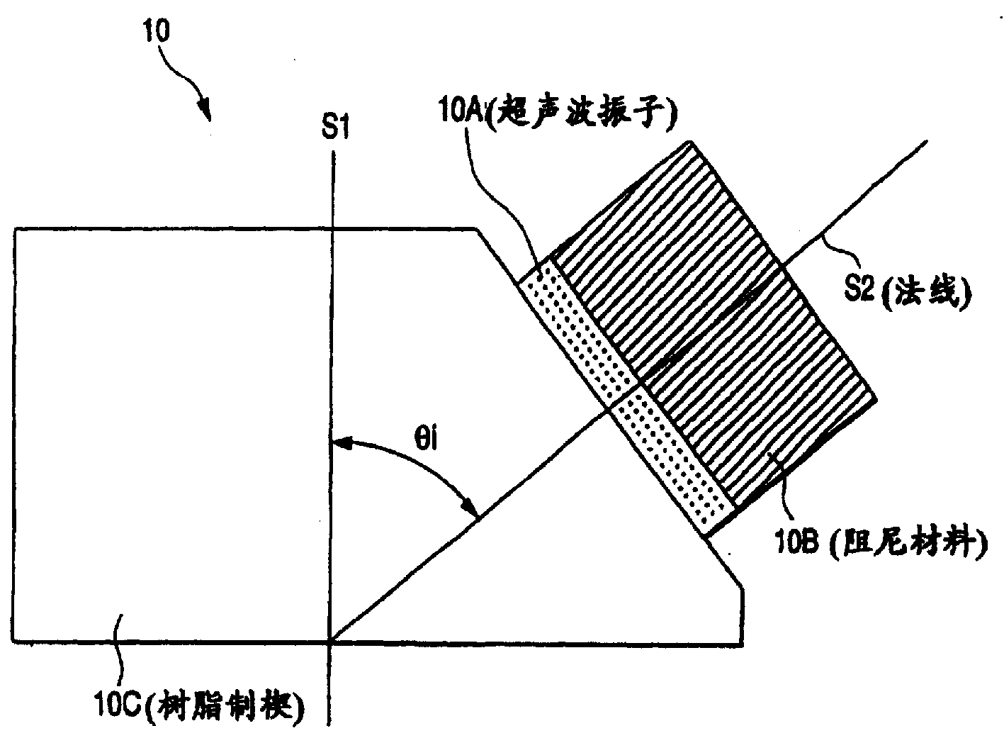
如图1所示,由于本发明的表面波探头10主要由超声波振子10A、阻尼材料10B、树脂制楔10C构成,设发送接收的表面波的中心频率为fc时,则前述表面波探头10的频带宽为0.50fc以上。As shown in FIG. 1, since the
即:如果现在表面波探头10发送接收的表面波频谱具有如图2概念上所示的频率分布,则规定频谱强度(信号强度)对峰值的比在-6dB以内范围的频宽fR-fL为频带宽,下列(2)式成立,That is: if the surface wave spectrum transmitted and received by the
fR-fL≥0.50fc ......(2)f R -f L ≥0.50fc ......(2)
这样一来,在本发明中设表面波探头10的频带宽为0.50fc以上宽的带宽。如果说明该表面波探头10的具体构成,则在上述超声波振子10A中用铌酸铅系瓷器或图23~25所示的复合物振子等机械Q值低的振子或者能够用钛酸铅系瓷器等,虽然机械Q值高,但也易受机械阻尼的振子。在这里所谓机械的Q值是表示共振锐度的量,机械Q值越高,则振动持续时间越长。因为散射噪声依被探伤材料的晶粒边界或表面粗糙度而异,所以发送接收的表面波中心频率fc有必要设定在合适的范围内。例如在辗压滚筒的情况下,最好在1~4MHZ。In this way, in the present invention, the frequency bandwidth of the
通过在上述阻尼材料10B中用将钨(金属)等比重大的粉体混合在环氧树脂等中加固的物体,并把它贴附在超声波振子10A的背面,以便对超声波振子10A内发生的超声波振动进行制动。因为钨(金属)等粉体的体积分率越大,阻尼材料的重量越大,则超声波振动的制动效果越大、超声波脉冲的脉宽变小。In the above-mentioned damping material 10B, an object that is reinforced by mixing tungsten (metal) and other specific powders in epoxy resin and the like, and attaching it to the back side of the ultrasonic vibrator 10A is used to prevent the vibration that occurs in the ultrasonic vibrator 10A. Ultrasonic vibrations for braking. Because the greater the volume fraction of powder such as tungsten (metal), the greater the weight of the damping material, the greater the braking effect of ultrasonic vibration, and the smaller the pulse width of ultrasonic pulses.
通过把超声波振子10A和阻尼材料10B作为上述所示的材料构成,可以生成(信号传送)频带宽0.5fc以上,脉宽为表面波波长2.5倍以下的超声波脉冲。By constituting the ultrasonic vibrator 10A and the damping material 10B as the above-mentioned materials, it is possible to generate (signal transmission) ultrasonic pulses having a frequency bandwidth of 0.5fc or more and a pulse width of 2.5 times or less the surface wave wavelength.
超声波发送接收面的法线S2对在该被检表面通过前述介质接触的底面法线S1的入射角为θ1,前述树脂制楔10C具有以入射角θi交叉的倾斜面,把超声波振子10A的前面(超声波发送接收面)贴附到该倾斜面上。以便如图1所示使超声波振动满足下述(3)式并入射到被检体。而且该楔10C本身用衰减率尽可能小的、例如聚苯乙烯树脂或聚酰胺树脂等形成,以便不损伤前述那样的短脉冲波形。The incident angle of the normal line S2 of the ultrasonic transmitting and receiving surface to the normal line S1 of the bottom surface contacted by the aforementioned medium on the surface to be inspected is θ1, and the aforementioned resin wedge 10C has an inclined surface intersecting at the incident angle θi. The front face (ultrasonic transmitting and receiving face) is attached to the inclined face. As shown in FIG. 1 , the ultrasonic vibration satisfies the following formula (3) and enters the subject. Furthermore, the wedge 10C itself is made of polystyrene resin or polyamide resin with as small an attenuation rate as possible so as not to damage the aforementioned short pulse waveform.
θi=Sin-1(CW/CR) ......(3)θ i =Sin -1 (CW/CR) ......(3)
式中CW:树脂制楔内的超声波速度,CR:圆柱体的表面波速度。In the formula, CW: the ultrasonic velocity in the resin wedge, CR: the surface wave velocity of the cylinder.
图3是通过种种变更阻尼材料的材质,制作频带宽不同的中心频率fc=2MHZ的表面波探头10,示出脉宽和频带宽关系的调查结果。在这里,频带宽与中心频率fc相等时作为100%表示。FIG. 3 shows the investigation results of the relationship between the pulse width and the frequency bandwidth by making a
由图3可以看到,如果频率带宽大于50%,则可以生成脉宽小于表面波波长2.5倍的短脉冲。而且使这样生成的脉宽短的表面波脉冲适合于无数地存在1次裂纹K的残存部分的滚筒缺陷的检测。正如用前述图21所说明的那样,在这种情况下,如果令表面波波长为λ,则一定存在离表面波探头10的距离差为λ/2的微小反射体K1~K4的组合。It can be seen from Figure 3 that if the frequency bandwidth is greater than 50%, a short pulse with a pulse width less than 2.5 times the wavelength of the surface wave can be generated. Furthermore, the thus generated surface wave pulse with a short pulse width is suitable for detection of a drum defect in which there are countless remaining portions of the primary crack K. As described above with reference to FIG. 21 , in this case, if the wavelength of the surface wave is λ, there must be a combination of microreflectors K1 to K4 whose distance difference from the
图4是示出用前述频宽为0.70fc以上,脉宽也为表面波波长1.5倍的短的超声波脉冲对存在上述微小反射体的区域探伤时的观测波形,这相当于前述传统侧的图22。Fig. 4 is an observation waveform showing the flaw detection of the area where the above-mentioned micro-reflector exists with the short ultrasonic pulse whose bandwidth is 0.70fc or more and whose pulse width is also 1.5 times the wavelength of the surface wave, which corresponds to the above-mentioned conventional diagram. twenty two.
如该图4所示,可以看到由于脉宽短,所以即使来自一次裂纹K的残存部分的微小振幅的反射波等相位叠加,振幅的增大作用也小。即:如果把可以发送接收脉宽短的表面波脉冲的本发明的表面波探头10用于无数地存在1次裂纹K残存部分的滚筒缺陷的检出,就能够有效地防止来自该1次裂纹K的残存部分的反射波的振幅增大。As shown in FIG. 4 , it can be seen that since the pulse width is short, even if the reflected waves with a small amplitude from the remaining portion of the primary crack K are superimposed in phase, the effect of increasing the amplitude is small. That is, if the
图5是示出用前述频带宽不同的(脉宽不同)中心频率2MHZ的表面探头对来自热加工辗压用前段工作辊的1次裂纹的反射波高度与(脉宽/表面波波长)关系进行调查的结果。其中以反射波的高度作为基准,测定来自直径1mm,深度1mm的纵方向的钻孔的反射波高度,1次裂纹K的深度约为0.15mm。Figure 5 shows the relationship between the reflected wave height and (pulse width/surface wave wavelength) of the primary crack from the front-stage work roll for thermal processing and rolling using the surface probe with a different frequency bandwidth (different pulse width) and a center frequency of 2 MHZ. the results of an investigation. Among them, the height of the reflected wave from a borehole in the longitudinal direction with a diameter of 1 mm and a depth of 1 mm was measured using the height of the reflected wave as a reference, and the depth of the primary crack K was about 0.15 mm.
图中作为实测点的A1,A2,A3与本发明相当,作为构成表面波探头10的超声波振子10A用铌酸铅系瓷器,此外作为阻尼材料10B用在环氧树脂内混合体积分率分别为80%,60%,40%的钨粉的阻尼材料。B1,B2相当于比较例。作为超声波振子用PZT,此外作为阻尼材料10B用在环氧树脂内混合体积分率分别为80%、60%的钨粉的阻尼材料。C1,C2相当于传统例,作为超声波振子10A用机械的Q值相互有若干差异的PZT,不用阻尼材料10B,除上述各点之外,实质上用同一装置测定。In the figure, A1, A2, and A3 as actual measurement points are equivalent to the present invention. As the ultrasonic vibrator 10A constituting the
由图5可以看到脉宽越短,1次裂纹K的反射波高度越低。It can be seen from Figure 5 that the shorter the pulse width is, the lower the reflected wave height of the primary crack K is.
其次,详细讨论适合超声波振子10A、树脂制楔10C的材质。作为阻尼材料10B,如前述所示,用在环氧树脂内混入钨粉加固的,在环氧树脂内混合钨粉的体积分率分别取80%,60%,40%,20%。作为超声波振子10A选择铌酸铅系瓷器、钛酸铅系瓷器、硅酸钛酸铅(PZT)、钛酸钡、铌酸锂、1-3型复合物振子(图23),0-3型复合物振子(图25),3-1型复合物振子(图24),此外,作为树脂制楔10C选择聚酰胺树脂,聚苯乙烯树脂,丙烯树脂,氟树脂(Teflon)制作表面波探头,测定发送接收的表面波频率带宽及脉宽,同时调查来自与图5所示结果的实验相同的热加工辗压用前段工作辊的1次裂纹的反射波高度。作为反射波高度的基准,测定直径1mm、深度1mm的纵向钻孔的反射波高度,与图5所示结果的实验完全相同。表2,表3,表4分别示出阻尼材料10B中的钨粉体积分率为80%时、60%时、40%时的实验结果。但是来自1次裂纹K的反射波高度比-11dB高的(来自1次裂纹K的反射波高度与传统的探头相比不低于3dB以上的)磨削掉,而超声波振子用PZT时的结果作为比较例为对比而完全示出。表5给出阻尼材料10B中钨粉的体积分率为20%时的实验结果,而来自1次裂纹K的反射波高度比-11dB高。如果看表2到表4,可以看到在所有情况下超声波振子10A内完全可能使用铌酸铅系瓷器、钛酸铅系瓷器,1-3型复合物振子,0-3型复合物振子,3-1型复合物振子。此外,可以看到在树脂制楔10B内完全可以使用聚酰胺树脂(2MHZ的超声波衰减常数:1.2×10-2dB/m),聚苯乙烯树脂(2MHZ的超声波衰减常数:1.3×10-2dB/m),丙烯树脂(2MHZ的超声波衰减常数:1.8×10-2dB/m),氟树脂(Teflon:2MHZ的超声波衰减常数:1.8×10-2dB/m)。因此,楔材在2MHZ的超声波衰减常数小于1.8×10-2dB/m就行了。把表2到表4与表5作比较,可以看到在阻尼材料10B中的钨粉体积分率必须大于40%。Next, materials suitable for the ultrasonic vibrator 10A and the resin wedge 10C will be discussed in detail. As the damping material 10B, as mentioned above, it is reinforced by mixing tungsten powder in epoxy resin, and the volume fraction of tungsten powder mixed in epoxy resin is 80%, 60%, 40%, and 20%, respectively. Lead niobate-based ceramics, lead titanate-based ceramics, lead silicate titanate (PZT), barium titanate, lithium niobate, 1-3 type composite vibrator (Fig. 23), and 0-3 type are selected as the ultrasonic vibrator 10A. Composite vibrator (Fig. 25), 3-1 type composite vibrator (Fig. 24), and polyamide resin, polystyrene resin, acrylic resin, fluororesin (Teflon) as the resin wedge 10C to make surface wave probe, The frequency bandwidth and pulse width of the transmitted and received surface wave were measured, and the height of the reflected wave from the primary crack of the front end work roll for hot rolling was investigated at the same time as the experiment with the results shown in Fig. 5 . As a reference for the reflected wave height, the reflected wave height of a longitudinal borehole with a diameter of 1 mm and a depth of 1 mm was measured, and the experiment was exactly the same as the result shown in Fig. 5 . Table 2, Table 3, and Table 4 respectively show the experimental results when the volume fraction of tungsten powder in the damping material 10B is 80%, 60%, and 40%. However, the height of the reflected wave from the primary crack K is higher than -11dB (the height of the reflected wave from the primary crack K is not lower than 3dB or more compared with the traditional probe), and the result when the ultrasonic vibrator uses PZT It is completely shown as a comparative example for comparison. Table 5 shows the experimental results when the volume fraction of tungsten powder in the damping material 10B is 20%, and the reflected wave height from the primary crack K is higher than -11dB. If you look at Table 2 to Table 4, you can see that it is entirely possible to use lead niobate-based porcelain, lead titanate-based porcelain, 1-3 type composite vibrator, and 0-3 type composite vibrator in ultrasonic vibrator 10A in all cases. 3-1 type complex oscillator. In addition, it can be seen that polyamide resin (ultrasonic attenuation constant at 2MHZ: 1.2× 10⁻² dB/m), polystyrene resin (ultrasonic attenuation constant at 2MHZ: 1.3× 10⁻² dB/m), acrylic resin (ultrasonic attenuation constant at 2MHZ: 1.8×10 -2 dB/m), fluororesin (Teflon: ultrasonic attenuation constant at 2MHZ: 1.8×10 -2 dB/m). Therefore, it is sufficient that the ultrasonic attenuation constant of the wedge material at 2MHZ is less than 1.8×10 -2 dB/m. Comparing Tables 2 to 4 with Table 5, it can be seen that the volume fraction of tungsten powder in the damping material 10B must be greater than 40%.
本发明者等依靠传统用的脉宽为表面波波长5倍的表面波探头对实质上同一条件下热加工辗压用的前段工作辊进行超声波探伤,不过,因为已经确认在最终一次的滚筒磨削前的磨削合格(Pass)后进行探伤和最终的磨削合格后进行探伤之间,来自1次裂纹的反射波可降低3dB,所以如果来自该1次裂纹K的反射波高度可降低3dB以上,则滚筒磨削合格次数至少能够减少一次。而且最终的滚筒磨削合格与否的判定由在磨削后测定的实测值是否在预定阈值以下来定。The inventors of the present invention rely on a conventional surface wave probe whose pulse width is 5 times the wavelength of the surface wave to perform ultrasonic flaw detection on the front-end work roll for thermal processing and rolling under substantially the same conditions. The reflected wave from the primary crack can be reduced by 3dB between the flaw detection after the grinding pass (pass) before cutting and the flaw detection after the final grinding pass, so if the reflected wave height from the primary crack K can be reduced by 3dB Above, the number of qualified drum grinding can be reduced at least once. And the judgment of whether the final drum grinding is acceptable or not is determined by whether the measured value measured after grinding is below a predetermined threshold.
因此,正如前述的图5所示,如果与用传统的脉宽为表面波波长5倍的表面波探头的测定值C1比较,能降低来自1次裂纹的反射波高度3dB以上的测定值的表面波探头的脉宽为小于表面波波长的2.5倍,则因为测定值A3和C1之差为3dB,所以对滚筒的磨削合格次数应该至少1次以上。Therefore, as shown in Fig. 5 above, compared with the measured value C1 of a conventional surface wave probe whose pulse width is 5 times the wavelength of the surface wave, the measured value of the height of the reflected wave from the primary crack can be reduced by more than 3dB. The pulse width of the wave probe is less than 2.5 times the wavelength of the surface wave, because the difference between the measured values A3 and C1 is 3dB, so the number of qualified grinding of the roller should be at least 1 time.
从图3可以认为:能够发送接收脉宽小于表面波波长2.5倍的表面波的表面波探头的带宽在50%以上是合适的。因此,可以看到通过设表面波探头的频带宽大于0.50fc,对能够降低1次裂纹过检产生的滚筒的过磨削有效果。这在本发明是表面波探头的频带宽取0.50fc以上的根据。From Figure 3, it can be considered that the bandwidth of the surface wave probe capable of sending and receiving surface waves whose pulse width is less than 2.5 times the wavelength of the surface wave is more than 50% is appropriate. Therefore, it can be seen that setting the frequency bandwidth of the surface wave probe to be greater than 0.50fc is effective in reducing the overgrinding of the drum that occurs in one pass inspection of cracks. This is the reason why the frequency bandwidth of the surface wave probe is 0.50fc or more in the present invention.
正如以上详述的那样,通过应用频带宽大于0.50fc,脉宽小于表面波波长2.5倍的表面波探头,对使用传统用的脉宽为表面波波长5倍程度的表面波探头的情况(图5中,C1点)和本发明的情况(A1~A3点)相比较,1次裂纹K的反射波高度可以降低3~6dB以上。As described in detail above, by using a surface wave probe with a frequency bandwidth greater than 0.50fc and a pulse width less than 2.5 times the wavelength of the surface wave, for the case of using a conventional surface wave probe with a pulse width approximately 5 times the wavelength of the surface wave (Fig. 5, point C1) compared with the case of the present invention (points A1 to A3), the reflected wave height of the primary crack K can be reduced by 3 to 6 dB or more.
同样地对于残存深度约0.1mm的1次裂纹K的辗压滚筒或残存深度约0.25mm的1次裂纹K的高速钢滚筒上生成的深度0.5mm的裂纹进行探伤时,用脉宽为表面波波长1.5倍的表面波探头,来自裂纹的反射波的S/N比为10dB,用脉宽为表面波波长2.5倍的表面波探头,来自裂纹的反射波的S/N比为7dB,与此相对应,用传统的脉宽为表面波波长5倍程度的表面波探头,S/N比为4dB。因此,如果采用本发明方法,与传统方法相比,使S/N比约提高3~6dB,能够大幅提高缺陷检出能力。Similarly, when detecting a crack with a depth of 0.5mm generated on a rolling roller with a primary crack K with a residual depth of about 0.1mm or a high-speed steel roller with a primary crack K with a residual depth of about 0.25mm, use the pulse width as the surface wave For a surface wave probe with 1.5 times the wavelength, the S/N ratio of the reflected wave from the crack is 10dB, and for a surface wave probe with a pulse width 2.5 times the wavelength of the surface wave, the S/N ratio of the reflected wave from the crack is 7dB. Correspondingly, using a conventional surface wave probe whose pulse width is about 5 times the wavelength of the surface wave, the S/N ratio is 4dB. Therefore, if the method of the present invention is adopted, compared with the conventional method, the S/N ratio is increased by about 3-6 dB, and the defect detection capability can be greatly improved.
其次,应用具有如前述图1所示的超声波振子10A、阻尼材料10B、树脂制楔10C分别由铌酸铅系瓷器、环氧树脂内混合60%体积分率的钨粉的阻尼材料、聚酰胺树脂所形成的表面波探头10的超声波探伤装置,对于500只热加工辗压用前段工作辊进行探伤,调查来自一次裂纹(热裂纹)的反射波降低到预定的水平以下的磨削量的实绩时,用直径换算的磨削量的实绩,在应用具有脉宽为表面波波长5倍程度的表面波探头的超声波探伤装置进行相同调查的传统例中为0.33mm,而用本发明可以磨削到0.2mm。Next, the ultrasonic vibrator 10A, the damping material 10B, and the resin wedge 10C as shown in FIG. The ultrasonic flaw detection device with the
这样一来,如果采用本发明,与传统技术相比,磨削量可以削减0.1mm以上。即使在这样削减的情况下,因在辗压滚筒表面生成的微小缺陷所发生的被辗压材料表面缺陷的程度与传统的几乎没有差别。In this way, if the present invention is adopted, the amount of grinding can be reduced by more than 0.1mm compared with the conventional technology. Even in the case of such cuts, the degree of surface defects of the rolled material due to minute defects generated on the surface of the rolling drum hardly differs from conventional ones.
在旋转的圆柱体表面通过介质液接触表面波探头,从该表面波探头对圆柱体传播表面波的同时,通过接收来自在圆柱体表面或紧挨表面下存在缺陷的反射波,在检出该缺陷的本发明超声波探伤装置中,配备以下装置以解决前述第3课题,这些装置包括:使前述圆柱体沿其周方向旋转的圆柱体旋转装置;检出由该圆柱体旋转装置产生的圆柱体转速的转速检出装置;在圆柱体上方对圆柱体表面以一定间隔保持前述表面波探头的定位装置;在该圆柱体轴向扫描的扫描装置;可把构成超声波传播介质的介质液供给到前述表面波探头和圆柱体表面之间、而且配备了可以根据前述圆柱体旋转装置产生的圆柱体转速,控制介质液供给量的流量控制阀的给水装置;在超声波振子的超声波发送接收面上配置的楔以及在超声振子的背面配置的阻尼材料,以便在设前述表面波探头发送接收的表面波中心频率为fc时,在该表面波的频谱内,相当于强度对峰值处于-6dB以内范围宽度的频带宽为0.50fc以上可以应用表面波检出缺陷的表面波探头;将用以发送表面波的电脉冲供给该表面波探头,把该表面波探头捕捉到的信号放大到判定缺陷必要的电平为止并输出的超声波发送接收器;从该超声波发送接收器输出的信号中取出应进行缺陷判定的信号,并输出的选通装置;以及检出该选通装置输出的信号振幅并输出,或者把该信号电平与预定阀值进行比较,当该信号电平大时,输出有缺陷的信号的缺陷判定装置。When the surface of the rotating cylinder contacts the surface wave probe through the medium liquid, while propagating the surface wave from the surface wave probe to the cylinder, by receiving the reflected wave from the defect existing on the surface of the cylinder or immediately under the surface, the surface wave is detected. The defective ultrasonic testing device of the present invention is equipped with the following devices to solve the aforementioned third problem. These devices include: a cylinder rotating device that rotates the aforementioned cylinder in its circumferential direction; and detects a cylinder generated by the cylinder rotating device. The rotating speed detecting device of the rotating speed; the positioning device for maintaining the aforementioned surface wave probe on the surface of the cylindrical body at a certain interval above the cylinder; the scanning device for scanning the axial direction of the cylindrical body; the medium liquid constituting the ultrasonic propagation medium can be supplied to the aforementioned Between the surface wave probe and the surface of the cylinder, there is also a water supply device that is equipped with a flow control valve that can control the supply of the medium liquid according to the rotation speed of the cylinder generated by the aforementioned cylinder rotation device; Wedge and the damping material arranged on the back of the ultrasonic vibrator, so that when the center frequency of the surface wave transmitted and received by the aforementioned surface wave probe is set as fc, in the frequency spectrum of the surface wave, the corresponding intensity is within -6dB of the peak value. A surface wave probe with a frequency bandwidth of 0.50fc or more that can be used to detect defects by surface waves; the electrical pulse used to send surface waves is supplied to the surface wave probe, and the signal captured by the surface wave probe is amplified to the necessary level for determining defects Ultrasonic transmitter and receiver for output; extract the signal that should be used for defect judgment from the signal output by the ultrasonic transmitter and receiver, and output the gating device; and detect the amplitude of the signal output by the gating device and output, or put A defect determination device that compares this signal level with a predetermined threshold value and outputs a defect signal when the signal level is greater.
尤其是前述楔具有在圆柱体表面通过接触介质接触的底面以及倾斜面,该倾斜面的法线对该底面部分的法线以前述(3)式规定的入射角θi相交叉,在该倾斜面上贴附前述超声波振子的超声波发送接收面的情况下,可以在圆柱体表面高效率传播表面波。In particular, the aforementioned wedge has a bottom surface contacted by a contact medium on the surface of the cylinder and an inclined surface, the normal line of the inclined surface intersects the normal line of the bottom surface portion at the incident angle θ i specified by the above-mentioned formula (3). In the case of attaching the above-mentioned ultrasonic vibrator to the ultrasonic transmitting and receiving surface, the surface wave can be efficiently propagated on the surface of the cylinder.
发明者们用有人工缺陷的高速钢滚筒,使该高速钢滚筒的转速变化,并且使从探头向滚筒表面的超声波传输稳定,而且过剩的介质液并不向探头前方流出,图6给出为了维持来自人工缺陷的反射波的高度为一定值调查合适的介质液(在本实验的情况用水)量的结果。如果处于打斜线的范围内的水量,则从探头到滚筒表面的超声波传递稳定。可以看出,随着高速钢滚筒的转速变大,媒介质液量也必须增大。而且,用转速检出装置测量高速钢滚筒的转速,根据高速钢滚筒的转速,通过应用在给水装置上设置的流量控制阀控制介质液的供给量,可以把合适量的介质液提供给到探头和高速钢滚筒表面之间,由此,能够维持从探头到滚筒表面的超声波传递稳定,并且可以防止过剩的介质液向探头前方流出。The inventors used a high-speed steel roller with artificial defects to change the speed of the high-speed steel roller and stabilize the ultrasonic transmission from the probe to the surface of the roller, and the excess medium liquid did not flow out to the front of the probe. Figure 6 shows The results of investigating the amount of suitable medium liquid (water in the case of this experiment) were maintained by maintaining the height of the reflected wave from the artificial defect at a constant value. If the amount of water is within the range marked with slashes, the transmission of ultrasonic waves from the probe to the surface of the drum is stable. It can be seen that as the speed of the high-speed steel drum increases, the amount of medium liquid must also increase. Moreover, the rotation speed of the high-speed steel drum is measured by the rotation speed detection device. According to the rotation speed of the high-speed steel drum, the supply amount of the medium liquid can be controlled by the flow control valve installed on the water supply device, and an appropriate amount of medium liquid can be supplied to the probe. and the surface of the high-speed steel roller, so that the ultrasonic transmission from the probe to the surface of the roller can be maintained stably, and the excess medium liquid can be prevented from flowing out to the front of the probe.
在表面上受到了热的、机械的损伤的滚筒磨削时,在磨削开始前或者在磨削过程中,边使滚筒旋转边通过接触介质的膜使滚筒表面与表面波探头接触,从表面波探头传播表面波,同时要除去滚筒表面中传播表面波部分的液体,测定来自在滚筒表面存在或残存的热的、机械的损伤部分的反射波高度,根据该反射波高度,设定其后的磨削量进行磨削,本发明是以此解决前述笫3课题的。When grinding a roller that has been thermally or mechanically damaged on the surface, before the grinding starts or during the grinding process, the surface of the roller is brought into contact with the surface wave probe through the film contacting the medium while rotating the roller, and the The wave probe propagates the surface wave, and at the same time removes the liquid in the part of the drum surface that propagates the surface wave, and measures the height of the reflected wave from the thermal and mechanical damage that exists or remains on the drum surface. Based on the height of the reflected wave, set the subsequent The amount of grinding is ground, and the present invention solves the aforementioned 3rd problem in this way.
在本发明中,通过媒介质与旋转的滚筒表面接触,至少由超声波振子和使超声波以入射角θi入射到滚筒表面的楔构成,以便在前述滚筒表面传播表面波那样配置,并且检出在前述滚筒表面和紧挨表面下存在的缺陷的滚筒检查用表面波探头中,通过设定其入射角θi以便满足下述(4)式,In the present invention, the medium is in contact with the surface of the rotating drum, and at least consists of an ultrasonic vibrator and a wedge that makes the ultrasonic waves incident on the drum surface at an incident angle θi , so that it is configured as a surface wave propagates on the aforementioned drum surface, and is detected at In the above-mentioned surface wave probe for inspecting the defects existing on the surface of the roller and immediately below the surface, by setting the incident angle θi thereof so as to satisfy the following formula (4),
θi=Sin-1(CW/CRav) ......(4)θ i =Sin -1 (CW/CRav) ......(4)
以此解决上述课题。This solves the above-mentioned problems.
式中,CW是楔内的超声波速度,CRav是作为检查对象的各滚筒的表面波速度的平均值。但入射角θi设为与滚筒表面正交的垂直面之间的角度。In the formula, CW is the ultrasonic velocity in the wedge, and CRav is the average value of the surface wave velocity of each roller to be inspected. However, the incident angle θi is set to be an angle between vertical planes perpendicular to the drum surface.
通过介质与旋转的滚筒表面接触,至少由超声波振子和使超声波以入射角θi入射到滚筒表面的楔构成,以便在前述滚筒表面传播表面波那样配置,并且作为检出在前述滚筒表面和紧挨表面下存在的缺陷的滚筒检查用的表面波探头的入射角设定方法,通过设定其入射角θi以便满足上述(4)式,来解决上述课题。The medium is in contact with the surface of the rotating drum, and at least consists of an ultrasonic vibrator and a wedge that makes the ultrasonic wave incident on the drum surface at an incident angle θi , so as to be configured so as to propagate surface waves on the drum surface, and as a detection method between the drum surface and the tight The method of setting the incident angle of the surface wave probe for the inspection of the surface of the defect exists by setting the incident angle θ i so as to satisfy the above-mentioned (4) formula, so as to solve the above-mentioned problem.
发明者们用前述表面波探头,通过边微小量地磨削受到辗压产生的热的、机械的损伤的辗压滚筒,边测定来自热的、机械的损伤部的反射波高度,调查来自热的、机械的损伤部分的反射波高度与热的、机械的损伤部残量(当反射波高度低于缺陷检出用阀值时看作无残量)之间的关系。图7给出其结果。可以很好看出,热的、机械的损伤部残量减少的同时,来自热的、机械的损伤部分的反射波高度也减小。如果从图7求出为了除去热的、机械的损伤部必要的磨削量和来自热的、机械的损伤部分的反射波高度之间的关系,则可得图8所示结果。因此,在磨削的开始前或磨削的过程中,通过用表面波的超声波探伤,测定来自热的、机械的损伤部分的反射波高度,如果用图8的关系决定磨削量,则能防止超过热的、机械的损伤部分的过磨削或者防止热的、机械的损伤部分的削残,可实现最佳的磨削。The inventors used the aforementioned surface wave probe to measure the height of the reflected wave from the thermally and mechanically damaged part while grinding a small amount of rolling rollers that were thermally and mechanically damaged by rolling, and investigated the source of thermal damage. The relationship between the reflected wave height of the mechanically damaged part and the residual amount of the thermally and mechanically damaged part (when the reflected wave height is lower than the threshold value for defect detection, it is regarded as no residual amount). Figure 7 shows the results. It can be clearly seen that the height of the reflected wave from the thermally and mechanically damaged portion decreases as the remaining amount of the thermally and mechanically damaged portion decreases. If the relationship between the amount of grinding required to remove thermal and mechanical damage and the height of the reflected wave from the thermal and mechanical damage is obtained from FIG. 7, the results shown in FIG. 8 can be obtained. Therefore, before the start of grinding or during the grinding process, the height of the reflected wave from the thermally and mechanically damaged part is measured by ultrasonic flaw detection with surface waves, and if the grinding amount is determined using the relationship in Fig. 8, it can be Optimum grinding is achieved by preventing overgrinding beyond thermally and mechanically damaged parts or preventing chipping of thermally and mechanically damaged parts.
尤其是在来自前述热的、机械的损伤部分的反射波高度处于最高处时,移动表面波探头及磨削用砂轮,边进行探伤边进行切入(plunge)磨削,求出来自热的、机械的损伤部分的反射波高度变为预定水平以下的磨削量,通过按照该磨削量,对残存的滚筒面磨削,可以实现最佳的磨削。In particular, when the height of the reflected wave from the aforementioned thermal and mechanical damage is at the highest point, move the surface wave probe and the grinding wheel, perform plunge grinding while performing flaw detection, and obtain the thermal and mechanical damage. Optimum grinding can be realized by grinding the remaining surface of the drum according to the grinding amount at which the height of the reflected wave of the damaged part becomes below a predetermined level.
即:如果在磨削开始前或磨削过程中,实施用表面波的超声波探伤,则如图7的关系所阐明的那样,来自热的、机械的损伤部分的反射波高度在最高处可以特定为热的、机械的损伤部分的残留量最多处。因此,如图9所示,使滚筒磨削装置的砂轮62和表面波探头10与辗压滚筒110接触的位置(滚筒的轴向位置)一致之后,在来自热的、机械的损伤部的反射波高度处于最高处时,滚筒磨削装置的砂轮62与表面波探头10接触。而且进行用表面波的超声波探伤,如果来自热的、机械的损伤部分的反射波高度一直下降到低于预定阀值,对辗压滚筒进行切入磨削,则这时的磨削量成为为了除去整个辗压滚筒面的热的、机械的损伤部分必要的磨削量。因此,将残留的滚筒的磨削量设定为该磨削量而进行磨削便行了。That is, if ultrasonic flaw detection with surface waves is carried out before or during grinding, as illustrated by the relationship in Figure 7, the height of reflected waves from thermal and mechanical damage can be specified at the highest point It is the place where the residual amount of thermal and mechanical damage is the largest. Therefore, as shown in FIG. 9 , after the position where the grinding wheel 62 of the drum grinding device and the
附图说明Description of drawings
图1是放大表示本发明的表面波探头的大致结构的断面图,FIG. 1 is an enlarged cross-sectional view showing a general structure of a surface wave probe of the present invention,
图2是用于说明前述表面波探头的频带宽的曲线图,Fig. 2 is a graph for explaining the frequency bandwidth of the aforementioned surface wave probe,
图3是表示前述表面波探头的频带宽和(脉宽/表面波波长)关系的曲线图,Fig. 3 is the graph that represents the frequency bandwidth of aforementioned surface wave probe and (pulse width/surface wave wavelength) relation,
图4是表示根据本发明的观测波形和来自微小反射体的反射波之间的关系的说明图,FIG. 4 is an explanatory diagram showing the relationship between observed waveforms according to the present invention and reflected waves from microreflectors,
图5是表示来自1次裂纹的反射波高度和(脉宽/表面波波长)关系的曲线图,Fig. 5 is a graph showing the relationship between the reflected wave height and (pulse width/surface wave wavelength) from a primary crack,
图6是表示为了用以说明本发明原理的滚筒转速和合适介质液量的关系的曲线图,Figure 6 is a graph showing the relationship between the rotational speed of the drum and the amount of suitable medium liquid in order to illustrate the principles of the present invention,
图7是表示为了说明本发明的来自热的、机械的损伤部分的反射波高度和热的、机械的损伤部分残留量关系的曲线图,Fig. 7 is a graph showing the relationship between the height of the reflected wave from the thermal and mechanical damaged part and the remaining amount of the thermal and mechanical damaged part in order to illustrate the present invention,
图8是表示为了说明本发明的必要的磨削量和来自热的、机械的损伤部分的反射波高度的关系的曲线图,Fig. 8 is a graph showing the relationship between the amount of grinding required for the present invention and the height of reflected waves from thermal and mechanical damage parts,
图9是表示为了说明本发明的切入磨削的砂轮和表面波探头的位置关系的斜视图,9 is a perspective view illustrating the positional relationship between the grinding wheel and the surface wave probe for plunge grinding according to the present invention,
图10是表示本发明的超声波探伤装置的第1实施例的大致结构的侧视图,Fig. 10 is a side view showing a schematic structure of a first embodiment of the ultrasonic flaw detection device of the present invention,
图11是放大表示第1实施例的探头座部分的正视图,Fig. 11 is an enlarged front view showing the probe holder portion of the first embodiment,
图12是剖断表示第1实施例的表面波探头上配备的给水部的主要部分侧视图,Fig. 12 is a cutaway side view showing the main part of the water supply unit provided in the surface wave probe of the first embodiment,
图13是表示本发明的超声波探伤装置的第2实施例的大致结构的侧视图,Fig. 13 is a side view showing a schematic structure of a second embodiment of the ultrasonic flaw detection device of the present invention,
图14是表示在第2实施例中改变滚筒转速进行探伤时的,来自缺陷的反射波高度和转速关系的调查结果的曲线图,Fig. 14 is a graph showing the investigation results of the relationship between the height of the reflected wave from a defect and the rotational speed when the rotational speed of the drum is changed for flaw detection in the second embodiment,
图15是表示本发明的超声波探伤装置的笫3实施例的大致结构的侧视图,Fig. 15 is a side view showing a schematic structure of a third embodiment of the ultrasonic flaw detection device of the present invention,
图16是表示本发明的超声波探伤装置的第4实施例的大致结构的侧视图,Fig. 16 is a side view showing a schematic structure of a fourth embodiment of an ultrasonic flaw detection device according to the present invention,
图17是表示用本发明的探头F和传统法的探头G、H,测定在5种滚筒上加工的人工缺陷的反射波高度的结果的图,Fig. 17 is a graph showing the results of measuring the reflected wave heights of artificial defects processed on five types of rollers with the probe F of the present invention and the probes G and H of the conventional method,
图18是表示用本发明的探头F和传统法的探头G、H,测定在5种滚筒上加工的人工缺陷的反射波的S/N比的结果的图,Fig. 18 is a graph showing the results of measuring the S/N ratios of reflected waves of artificial defects processed on five types of rollers with the probe F of the present invention and the probes G and H of the conventional method,
图19用S/N比表示使用本发明的探头F和传统法的探头G、H对20个表面缺陷进行探伤检查结果的图,Fig. 19 shows the results of flaw detection of 20 surface defects using the probe F of the present invention and the probes G and H of the conventional method in terms of S/N ratio,
图20是为了说用热加工辗压用工作辊在周向的表面上产生的裂纹的概念图,FIG. 20 is a conceptual diagram for explaining cracks generated on the circumferential surface of work rolls for hot-working rolling,
图21是表示表面波探头和微小反射体的位置关系的说明图,FIG. 21 is an explanatory diagram showing the positional relationship between a surface wave probe and a microreflector,
图22是表示用传统法的观测波形和来自微小反射体的反射波之间关系的说明图,Fig. 22 is an explanatory diagram showing the relationship between the observed waveform by the conventional method and the reflected wave from a micro reflector,
图23是本发明的探头振子的一例(1-3型复合物振子),Fig. 23 is an example of the probe vibrator (1-3 type composite vibrator) of the present invention,
图24是本发明的探头振子的一例(3-1型复合物振子),Fig. 24 is an example (3-1 type composite vibrator) of the probe vibrator of the present invention,
图25是本发明的探头振子的一例(0-3型复合物振子)。Fig. 25 is an example of a probe vibrator (0-3 type composite vibrator) of the present invention.
具体实施方式Detailed ways
参照以下附图,详细说明本发明的实施例。Embodiments of the present invention will be described in detail with reference to the following drawings.
图10是表示本发明的超声波探伤装置第1实施例的概咯侧视图。Fig. 10 is a schematic side view showing a first embodiment of the ultrasonic flaw detection apparatus of the present invention.
本实施例的超声波探伤装置是把图中符号110所示的辗压滚筒作为被检体,作为基本构成包括:使该滚筒110旋转的滚筒旋转装置,用于发送接收该滚筒110的表面波的表面波探头10,用于支撑该探头10的探头座12,附置在该座12上、把接触介质(水)供给到滚筒110的表面和表面波探头10之间的给水装置(后述)。The ultrasonic flaw detection device of this embodiment uses the rolling roller shown by the
作为前述滚筒旋转装置为避免附图的复杂化而省略了其图示,如果使检查对象的辗压滚筒110也能够沿其圆周方向C旋转,则可以用公知的合适的装置。As the roll rotating device, the illustration is omitted to avoid complicating the drawings, but if the rolling
调整振子种类或阻尼材料的组成,以便使前述表面波探头10可能发送接收频带宽大于0.50fc,脉宽小于表面波波长2.5倍的表面波。Adjust the type of vibrator or the composition of the damping material so that the aforementioned
在该表面波探头10上,在该探头10和作为被检体的辗压滚筒110表面之间间隙内形成充满水(介质液)的状态,通过该水,使超声波在滚筒110的表面上传播,在该滚筒110上传递表面波,通过发送接收该反射波应该可以检出辗压滚筒110的表面缺陷。On the
支撑该表面波探头10的前述探头座12定位在对位于辗压滚筒110上方的固定构造部件14,在可以上下方向滑动的导杆16的下部安装的定位机构部18上。在该定位机构部18中配备前后各一对、计4个滚筒20,在这些滚筒20之间配置上述的探头座12。而且,在进行探伤时,通过这4个滚筒20与辗压滚筒110的表面接触、旋转,使探伤扫描稳定。The
在前述固定构造部14上配备有马达14A及其安装底板14B,该马达用于通过公知的传递装置(未图示)提供使定位机构部18沿导杆16升降的动力。A
该固定构造部14通过省略图示的扫描装置可以沿辗压滚筒110的轴向扫描,由此可以使表面波探头10沿辗压滚筒110的轴向扫描。The fixed
前述的探头座12安装在对定位机构部18可以上下移动地松转动配合的棒状体12A的下端,通过夹装于该棒状体12A周围的预定位置上的弹簧(未图示),常常在图中下方,即对辗压滚筒110的表面用适当力在压紧的状态下支撑着。The
为了在前述表面波探头10和辗压滚筒110之间形成预定的间隙,在前述探头座12上设置一对仿形滚筒22,它们向比该表面波探头10还下方的辗压滚筒110一侧突出。In order to form a predetermined gap between the
图11是放大表示该状态正视图,在沿着水平方向(滚筒轴向)探头座12对置的两侧部上分别设置轴24,在其两侧上可以旋转地分别安装了上述仿形滚筒22,这样一来,轴支承在探头座12上的仿形滚筒22通过承受前述弹簧适当的压力能够在测量时常常与辗压滚筒110的表面接触,通过这种结构用探头座12能支撑前述表面波探头10,以便在表面波探头10和辗压滚筒110之间常常维持一定的间隙。Fig. 11 is an enlarged front view showing this state.
在该表面波探头10,正如分别用两点划线表示探头座12和仿形滚筒22的轮廓,省略的图12所示,在其内部配备有供水部(给水装置)26,从导管28导出的水暂时收容在收容部26A内,由设置在收容部26A底部上的放出孔26B把它放出,应当能在表面波探头10和辗压滚筒110之间形成无气泡的水层。因为给水装置用传统的已知的恰当装置构成便行了,省略详细说明。In this
在图10中,符号30是除去该水的刮板,以便如以上所述由给水部供给的水残留在滚筒表面而不致流到表面波的传播路上。In FIG. 10,
因为本实施例的超声波探伤装置作为以上详述的装置构成,所以把作为超声波传播介质的水供给到表面波探头10和作为被检体的辗压滚筒110的表面之间,同时可以容易且可靠执行边在其表面上扫描移动该探头10边进行探伤作业。Since the ultrasonic flaw detection device of this embodiment is constituted as the device described in detail above, it is easy and reliable to supply water as an ultrasonic propagation medium between the
用本实施例,对500只热加工辗压用前段工作辊(高速钢滚筒)进行探伤,在调查来自称作热裂纹的1次裂纹的反射波降低到预定水平以下的磨削量的实绩时,应用传统的脉宽为表面波波长5倍程度的表面波探头的探伤装置的磨削量实绩(直径换算)为0.33mm,而在本实施例变成0.20mm,与传统相比,确认可以削减磨削量0.1mm以上。即使在这种情况下由高速钢滚筒表面的微小缺陷产生的被辗压材料的表面缺陷发生与传统的几乎没有差别。In this example, 500 front-stage work rolls (high-speed steel rolls) for hot rolling were inspected to investigate the actual performance of the amount of grinding that reduced the reflected wave from the primary crack called a hot crack to a predetermined level or less. , the actual grinding amount (diameter conversion) of the flaw detection device using the traditional surface wave probe whose pulse width is about 5 times the surface wave wavelength is 0.33mm, but in this embodiment it becomes 0.20mm. Compared with the conventional one, it can be confirmed that Reduce the amount of grinding by more than 0.1mm. Even in this case, the occurrence of surface defects of the rolled material caused by minute defects on the surface of the high-speed steel roller is almost indistinguishable from the conventional one.
其次,参照图13,详细说明适合于扫描移动表面波探头10对高速钢滚筒的表面探伤的本发明的第2实施例。Next, referring to FIG. 13 , a second embodiment of the present invention suitable for surface flaw detection of a high-speed steel roll with a scanning-moving
在本实施例中,设辗压滚筒110为高速钢滚筒,该高速钢滚筒的转速由转速检出器32检出,送到在给水装置上配备的流量控制阀34,控制流量在适合于图6所示的范围内。表面波探头10的输出经超声波发送接收器40以及门电路42,输入到缺陷判定电路44。In this embodiment, the rolling
前述超声波发送接收器40将用以发送表面波的电脉冲供给前述表面波探头10,该表面波探头10把接收的信号放大到判定缺陷必要的电平,并输出到门电路42。门电路42从前述超声波发送接收器40输出的信号中抽出应进行缺陷判定的信号,并输出到缺陷判定电路44。缺陷判定电路44检出门电路42输出的信号振幅并输出或者把该信号的电平与预定的阀值比较,当该信号电平大时动作,以便输出有缺陷的信号,由此检出表面缺陷。The ultrasonic transmitter-
前述探头座12与第1实施例一样,如图12所示,在内部配备给水部26。该给水部26通过流量控制阀34确定与辗压滚筒110的转速(周速)相适应的流量,把从导管28导出的水暂时收容在收容部26A内,让它从设置于收容部26A底部的放出口26B放出,在表面波探头10和辗压滚筒110之间形成无气泡的水层。Like the first embodiment, the
因为关于其它点与第1实施例相同,用相同符号,省略详细说明。Since other points are the same as those in the first embodiment, the same symbols are used, and detailed description is omitted.
用本实施例的装置改变转速从25rpm到50rpm对有表面缺陷的高速钢滚筒进行探伤,在图14给出调查来自缺陷的反射波高度和转速的关系的结果。如果采用本实施例的装置,可以与高速钢转速无关、很好地检出表面缺陷。Use the device of this embodiment to change the rotational speed from 25rpm to 50rpm to carry out flaw detection on a high-speed steel roller with surface defects. Figure 14 shows the results of investigating the relationship between the height of the reflected wave from the defect and the rotational speed. If the device of this embodiment is used, surface defects can be detected well regardless of the speed of the high-speed steel.
其次参照图15,详细说明本发明的第3实施例。Next, referring to Fig. 15, a third embodiment of the present invention will be described in detail.
本实施例在磨削开始前或磨削中途进行用表面波的超声波探伤,测定来自热的、机械的损伤部的反射波高度,给出了向辗压滚筒110的磨削装置60传送磨削量设定值的装置。辗压滚筒的磨削装置用传统已知的恰当装置就行了。为避免附图复杂化,省略图示。In this embodiment, ultrasonic flaw detection using surface waves is carried out before or during grinding, and the height of reflected waves from thermal and mechanical damage is measured, and the grinding
在前述表面波探头10上连接超声波探伤器50,把用于从表面波探头10发送表面波的电脉冲供给表面波探头10,把表面波探头10接收的信号放大到适于缺陷判定的电平,此外,超声波探伤器50用与第2实施例同样的门电路(图示省略),从放大后的信号抽出来自热的、机械的损伤的反射波,检出其高度。由超声波探伤器50检出的来自热的、机械的损伤部分的反射波高度送到计算机52,通过参照图8的关系,求出为除去热的、机械的损伤部必要的磨削量。如此求出的磨削量的设定值送到辗压滚筒的磨削装置60,例如用砂轮实施磨削。Connect the
因为关于其它点与第1、第2实施例相同,用相同符号,省略其详细说明。Since other points are the same as those in the first and second embodiments, the same symbols are used, and detailed description thereof will be omitted.
用本实施例中,对200只热加工辗压用前段工作辊进行探伤,调查磨削量的实绩时,而采用传统方式进行的、把一定量的磨削重复到来自热的、机械的损伤部分的反射波低于预定阀值的方法的磨削量推算值(从对每1只滚筒用本装置的磨削量的实际值推算传统法的磨削量)经直径换算为0.23mm,而采用本实施例经直径换算为0.18mm,与传统方式相比,确认磨削量可削减0.05mm以上。In this example, when inspecting 200 front-stage work rolls for hot rolling and investigating the actual performance of the amount of grinding, the traditional method of repeating a certain amount of grinding to damage from heat and machinery The estimated value of the grinding amount of the method in which part of the reflected wave is lower than the predetermined threshold value (the grinding amount of the traditional method is estimated from the actual value of the grinding amount of this device for each roller) is converted to 0.23mm by diameter, and Using this embodiment, the diameter is converted to 0.18mm. Compared with the traditional method, it is confirmed that the grinding amount can be reduced by more than 0.05mm.
其次,参照图16,详细说明本发明的第4实施例。Next, referring to Fig. 16, a fourth embodiment of the present invention will be described in detail.
在本实施例,设置了检出表面波探头10的滚筒轴向位置的位置检出器36,从该位置检出器36检出表面波探头10在滚筒轴向的位置,送到计算机52,在磨削开始前或磨削中途进行的用表面波的超声波探伤中,求出来自热的、机械的损伤部分的反射波高度最高部分在辗压滚筒上的位置。此外,在进行称为切入磨削的磨削时,如图9所示,表面波探头10在机械上定位设置,以便使表面波探头10和砂轮62与辗压滚筒110接触的位置(滚筒的轴向位置)一致。In this embodiment, a position detector 36 for detecting the axial position of the drum of the
关于其它构成,因为与第3实施例相同,所以用相同符号,省略详细说明。The other configurations are the same as those of the third embodiment, so the same symbols are used, and detailed descriptions are omitted.
以下详细说明本实施例的运作。首先,在磨削开始前或磨削中途,通过使辗压滚筒110边沿其圆周方向C旋转,边使表面波探头10沿辗压滚筒110的轴向扫描,对整个辗压滚筒面进行用表面波的超声波探伤,通过输入来自热的、机械的损伤部分的反射波高度以及表面波探头10的位置检出信号的计算机52求出来自热的、机械的损伤部分的反射波高度的最高部分在辗压滚筒110上的位置。The operation of this embodiment will be described in detail below. First, before the grinding starts or in the middle of the grinding, the
其次,如图9所示,在该位置移动表面波探头10和砂轮62,直到来自热的、机械的损伤部分的反射波高度低于预定阀值为止,边进行用表面波的超声波探伤、边进行辗压110滚筒的切入磨削,求出这时的磨削量。Next, as shown in FIG. 9, the
把这样求出的磨削量的设定值输入到辗压滚筒的磨削装置60,进行残留的滚筒面的磨削。The set value of the amount of grinding obtained in this way is input to the grinding
用本实施例的装置,对200只热加工辗压用前段工作辊进行探伤,调查磨削量的实绩,而采用传统方式进行的、把一定量的磨削重复到来自热的、机械的损伤部分的反射波低于预定阀值的方法的磨削量推算值,经直径换算为0.24mm,而采用本实施例经直径换算为0.19mm,与传统方式相比,确认磨削量可削减0.05mm以上。Using the device of this example, 200 front-stage work rolls for hot rolling are inspected to investigate the actual performance of the amount of grinding. However, the traditional method of repeating a certain amount of grinding to damage from heat and machinery The estimated grinding amount of the part of the reflected wave is lower than the predetermined threshold value, which is 0.24mm by diameter conversion, but using this embodiment is 0.19mm by diameter conversion. Compared with the traditional method, it is confirmed that the grinding amount can be reduced by 0.05 mm or more.
其次用图17和图18详细说明本发明的第5实施例。Next, a fifth embodiment of the present invention will be described in detail with reference to Fig. 17 and Fig. 18 .
图17和图18是表示用本发明的表面波探头和2种传统方式的表面波探头测定表1所示的5种滚筒上加工的人工缺陷结果的图。图17是测定人工缺陷的反射波高度的图,图18是测定人工缺陷的反射波的S/N比的图。人工缺陷采用在各自的滚筒的表面上加工1mmφ、1mm深度的纵向钻孔。在这里设表面波探头的楔为聚苯乙烯树脂(CW=2340m/sec)制作。Fig. 17 and Fig. 18 are graphs showing the results of measuring the artificial defects of the five types of rollers shown in Table 1 using the surface wave probe of the present invention and two conventional surface wave probes. FIG. 17 is a diagram for measuring the height of reflected waves of artificial defects, and FIG. 18 is a diagram for measuring the S/N ratio of reflected waves for artificial defects. As for the artificial defect, longitudinal drilling of 1 mmφ and 1 mm depth was processed on the surface of each drum. Here, the wedge of the surface wave probe is assumed to be made of polystyrene resin (CW=2340m/sec).
表面波探头如前所述预备如下3种。探头F:是对作为对象的5种滚筒的表面波速度取平均,构成的表面波探头,以使其符合由该平均值CRav和聚苯乙烯树脂的超声波速度CW用(2)式算出的θi。即:取θi=48.1度。是本发明的表面波探头。探头G:构成的表面波探头符合由表1的滚筒4号的表面波速度和聚苯乙烯树脂的超声波速度算出的θi,即取θi=49.2度。是传统的表面波探头。探头H:构成的表面波探头符合由普通钢的表面波速度(2980m/sec)和聚苯乙烯树脂的超声波速度算出的θi,即:取θi=51.7度。是另外的传统例的表面波探头。The following three types of surface wave probes were prepared as described above. Probe F: A surface wave probe that averages the surface wave velocities of the five types of rollers to be tested so that it conforms to θ calculated from the average value CRav and the ultrasonic velocity CW of polystyrene resin using the formula (2). i . Namely: take θ i =48.1 degrees. It is the surface wave probe of the present invention. Probe G: The constituted surface wave probe complies with θi calculated from the surface wave velocity of drum No. 4 in Table 1 and the ultrasonic velocity of polystyrene resin, that is, θi = 49.2 degrees. Is the traditional surface wave probe. Probe H: The constituted surface wave probe complies with θi calculated from the surface wave velocity of ordinary steel (2980m/sec) and the ultrasonic velocity of polystyrene resin, that is, θi = 51.7 degrees. It is the surface wave probe of another conventional example.
由图17和18可以确认:本发明的探头F稳定地得到与滚筒的种类无关的高的反射波高度及S/N比。在这里图17的纵轴令在表面波探头F对滚筒1号的人工缺陷探伤时的反射波高度为0dB表示。It can be confirmed from FIGS. 17 and 18 that the probe F of the present invention stably obtains a high reflected wave height and a high S/N ratio regardless of the type of the drum. Here, the vertical axis in FIG. 17 represents that the height of the reflected wave when the surface wave probe F detects the artificial flaw of drum No. 1 is 0 dB.
其次,从实际的滚筒中对表1所示的5种滚筒上各附有4个、共计20个表面缺陷抽样,测定来自这些表面缺陷的反射波的S/N比。图19是对20个表面缺陷全部附上编号并以该编号作横轴,S/N作纵轴的图表化。在这里,表面波探头适用前述的3种探头F、G、H。从图19也通过应用本发明的探头F,确认即使对实际的表面缺陷也能稳定地以高S/N比进行探伤。Next, a total of 20 surface defects were sampled from actual rollers with 4 surface defects attached to each of the five types of rollers shown in Table 1, and the S/N ratios of reflected waves from these surface defects were measured. FIG. 19 is a graph in which numbers are assigned to all 20 surface defects, the numbers are plotted on the horizontal axis, and S/N is plotted on the vertical axis. Here, the surface wave probes are applicable to the aforementioned three types of probes F, G, and H. Also from FIG. 19 , by applying the probe F of the present invention, it was confirmed that even actual surface defects can be stably detected with a high S/N ratio.
以上就本发明作了具体的说明,但本发明并不限于前述实施例,在不脱离其要旨的范围内可作种种变更。例如作为构成表面波探头的构件的超声波振子10A、阻尼材料10B、树脂制楔10C的具体材料不限于前述实施例所示的,如果是具有同样功能的、则可以利用任意的材料。The present invention has been specifically described above, but the present invention is not limited to the foregoing embodiments, and various changes can be made without departing from the gist thereof. For example, specific materials of the ultrasonic vibrator 10A, the damping material 10B, and the resin wedge 10C as components constituting the surface wave probe are not limited to those shown in the foregoing embodiments, and any material can be used as long as it has the same function.
在前述实施例,给出用水作为接触介质的情况,但也可以应用油等其它的液体。In the foregoing embodiments, water is used as the contact medium, but other liquids such as oil may also be used.
本发明应用对象不限于辗压滚筒、尤其不限于高速钢滚筒,如果是由金属等构成的辗压机等的圆柱体则没有特殊限制。The application object of the present invention is not limited to rolling rollers, especially not limited to high-speed steel rollers, and there is no special limitation if it is a cylinder of a rolling machine or the like made of metal or the like.
表1
表2钨粉的体积分率:80%
表3table 3
钨粉的体积分率:60%
表4Table 4
钨粉的体积分率:40%
表5table 5
钨粉的体积分率:20%
工业上利用的可能性。Possibility of industrial use.
如果采用本发明,则能够在用表面波进行超声波探伤时,防止1次裂纹的过检出,防止因过磨削产生的滚筒原耗变差。此外,能够降低来自1次裂纹或晶粉边界的噪声电平、大幅度提高缺陷检出能力。According to the present invention, it is possible to prevent over-detection of primary cracks during ultrasonic flaw detection using surface waves, and to prevent deterioration of the original wear of the drum due to over-grinding. In addition, noise levels from primary cracks and grain boundaries can be reduced, and defect detection capabilities can be greatly improved.
尤其是因辗压在表面上受到热的、机械的损伤的辗压滚筒的磨削时,想要根据来自热的、机械的损伤的反射波高度去设定其后的磨削量时,使滚筒的磨削量最佳化、提高滚筒的原耗,同时提高滚筒的磨削效率。Especially when grinding rollers that are subjected to thermal and mechanical damage due to rolling on the surface, when it is desired to set the subsequent grinding amount according to the height of the reflected wave from thermal and mechanical damage, use The grinding amount of the roller is optimized, the original consumption of the roller is increased, and the grinding efficiency of the roller is improved at the same time.
此外,在用表面波的滚筒超声波探伤法的本发明的应用时尽管因制造法的不同产生的滚筒材质的不同,仍然能够高效率发送接收表面波,能够不更换表面波探头去探伤,能用共同的表面波探头提高来自缺陷的反射波的S/N比。In addition, when the present invention is applied to the roller ultrasonic flaw detection method using surface waves, despite the difference in the roller material due to the difference in the manufacturing method, the surface wave can still be sent and received with high efficiency, and the flaw detection can be performed without replacing the surface wave probe. A common surface wave probe improves the S/N ratio of reflected waves from defects.
Claims (1)
Applications Claiming Priority (9)
| Application Number | Priority Date | Filing Date | Title |
|---|---|---|---|
| JP9300409A JPH11133005A (en) | 1997-10-31 | 1997-10-31 | Surface wave probe for roll inspection and its incident angle setting method |
| JP300409/1997 | 1997-10-31 | ||
| JP300409/97 | 1997-10-31 | ||
| JP330213/97 | 1997-12-01 | ||
| JP33021397 | 1997-12-01 | ||
| JP330213/1997 | 1997-12-01 | ||
| JP128912/1998 | 1998-05-12 | ||
| JP12891298 | 1998-05-12 | ||
| JP128912/98 | 1998-05-12 |
Related Parent Applications (1)
| Application Number | Title | Priority Date | Filing Date |
|---|---|---|---|
| CNB988029502A Division CN1163746C (en) | 1997-10-31 | 1998-10-29 | Ultrasonic flaw detection method and flaw detection device for cylinder surface, and method for grinding cylinder using the same |
Publications (2)
| Publication Number | Publication Date |
|---|---|
| CN1515900A CN1515900A (en) | 2004-07-28 |
| CN1253713C true CN1253713C (en) | 2006-04-26 |
Family
ID=27315835
Family Applications (3)
| Application Number | Title | Priority Date | Filing Date |
|---|---|---|---|
| CNB031368867A Expired - Fee Related CN1253713C (en) | 1997-10-31 | 1998-10-29 | Ultrasonic flaw detection method on cylinder surface |
| CNB988029502A Expired - Fee Related CN1163746C (en) | 1997-10-31 | 1998-10-29 | Ultrasonic flaw detection method and flaw detection device for cylinder surface, and method for grinding cylinder using the same |
| CNB021442673A Expired - Fee Related CN1254679C (en) | 1997-10-31 | 1998-10-29 | Grinding method of drum using supersonic flaw detection method and device |
Family Applications After (2)
| Application Number | Title | Priority Date | Filing Date |
|---|---|---|---|
| CNB988029502A Expired - Fee Related CN1163746C (en) | 1997-10-31 | 1998-10-29 | Ultrasonic flaw detection method and flaw detection device for cylinder surface, and method for grinding cylinder using the same |
| CNB021442673A Expired - Fee Related CN1254679C (en) | 1997-10-31 | 1998-10-29 | Grinding method of drum using supersonic flaw detection method and device |
Country Status (9)
| Country | Link |
|---|---|
| US (2) | US6446509B1 (en) |
| EP (1) | EP0965839A4 (en) |
| KR (2) | KR100400184B1 (en) |
| CN (3) | CN1253713C (en) |
| AU (1) | AU752801C (en) |
| BR (1) | BR9806287B1 (en) |
| CA (1) | CA2276319C (en) |
| TW (1) | TW572208U (en) |
| WO (1) | WO1999023486A1 (en) |
Cited By (1)
| Publication number | Priority date | Publication date | Assignee | Title |
|---|---|---|---|---|
| CN101446569B (en) * | 2008-12-31 | 2010-12-22 | 东北轻合金有限责任公司 | Ultrasonic fault detection method for heat check compound filling defect of thick-wall aluminum alloy pipe |
Families Citing this family (50)
| Publication number | Priority date | Publication date | Assignee | Title |
|---|---|---|---|---|
| US7789841B2 (en) | 1997-02-06 | 2010-09-07 | Exogen, Inc. | Method and apparatus for connective tissue treatment |
| US7108663B2 (en) | 1997-02-06 | 2006-09-19 | Exogen, Inc. | Method and apparatus for cartilage growth stimulation |
| US5904659A (en) | 1997-02-14 | 1999-05-18 | Exogen, Inc. | Ultrasonic treatment for wounds |
| DE69933555T2 (en) | 1998-05-06 | 2007-06-14 | Exogen, Inc., Memphis | ULTRASOUND SUPPORTS |
| WO2000052239A1 (en) * | 1999-03-04 | 2000-09-08 | Zellweger Luwa Ag | Method and device for conducting quality control of textile strips |
| US6923067B2 (en) * | 1999-03-19 | 2005-08-02 | Betriebsforschungsinstitut Vdeh Institut Fur Angewandte Forschung Gmbh | Defect type classifying method |
| CN100342929C (en) | 1999-05-21 | 2007-10-17 | 伊爱克斯奥根公司 | Apparatus and method for altrasonically and electromagnetically treating tissue |
| TW490559B (en) * | 1999-07-30 | 2002-06-11 | Hitachi Construction Machinery | Ultrasonic inspection apparatus and ultrasonic detector |
| DE19955136A1 (en) * | 1999-11-17 | 2001-05-31 | Sms Demag Ag | Method and device for non-contact online hot wall thickness measurement on pipes |
| WO2002040099A2 (en) | 2000-10-25 | 2002-05-23 | Exogen, Inc. | Transducer mounting assembly |
| US7429248B1 (en) * | 2001-08-09 | 2008-09-30 | Exogen, Inc. | Method and apparatus for controlling acoustic modes in tissue healing applications |
| KR100862035B1 (en) * | 2002-06-21 | 2008-10-07 | 주식회사 포스코 | Rolling Roll Defect Automatic Detection Device |
| KR100824523B1 (en) * | 2002-07-06 | 2008-04-22 | 주식회사 포스코 | Rolling roll surface defect detection device |
| KR100879344B1 (en) * | 2002-07-12 | 2009-01-19 | 주식회사 포스코 | Roll defect inspection device |
| EP1447661A1 (en) * | 2002-12-24 | 2004-08-18 | Innerspec Technologies, Inc. | Creeping wave technique for mill roll inspection |
| CA2456566C (en) * | 2003-01-31 | 2008-12-02 | Universidad Tecnica Federico Santa Maria | System and method of measuring and classifying the impacts inside a revolving mill used in mineral grinding |
| CA2456608C (en) * | 2003-01-31 | 2009-01-06 | Universidad Tecnica Federico Santa Maria | A system to determine and analyze the dynamic internal load in revolving mills, for mineral grinding |
| US7293461B1 (en) * | 2003-10-22 | 2007-11-13 | Richard Girndt | Ultrasonic tubulars inspection device |
| DE102004051020A1 (en) * | 2004-10-20 | 2006-05-04 | Sms Demag Ag | Method, apparatus and circuit for detecting surface defects such as cracks, eruptions and the like on a roll of a rolling mill |
| DE102005038344A1 (en) * | 2005-08-13 | 2007-02-15 | Tetra Laval Holdings & Finance S.A. | Device for ultrasonic machining of workpieces |
| DE102005044760B3 (en) * | 2005-09-20 | 2007-04-12 | Georgsmarienhütte Gmbh | Apparatus for ultrasonic testing of hot rolled material |
| US7562593B2 (en) * | 2005-10-06 | 2009-07-21 | The Boeing Company | Apparatus and methods for adjustably supporting probes |
| US20070089549A1 (en) * | 2005-10-06 | 2007-04-26 | The Boeing Company | Apparatus and methods for adjustably supporting probes |
| US7464594B2 (en) * | 2006-09-21 | 2008-12-16 | International Business Machines Corporation | System and method for sensing a paper roll ultrasonically |
| US8656782B2 (en) | 2007-03-15 | 2014-02-25 | Siemens Aktiengesellschaft | Method and device for non-destructive material testing of a test object using ultrasonic waves |
| US7757558B2 (en) * | 2007-03-19 | 2010-07-20 | The Boeing Company | Method and apparatus for inspecting a workpiece with angularly offset ultrasonic signals |
| US7712369B2 (en) * | 2007-11-27 | 2010-05-11 | The Boeing Company | Array-based system and method for inspecting a workpiece with backscattered ultrasonic signals |
| CN101264582B (en) * | 2008-04-24 | 2010-12-15 | 昆山华辰机器制造有限公司 | Roll grinding machine high precision full-automatic on-line measurement system |
| CN101587098B (en) * | 2008-05-21 | 2012-05-16 | 山东省科学院激光研究所 | Ultrasonic flaw detection method for steel pipes with one channel realizing three functions at the same time |
| ITTV20080109A1 (en) * | 2008-08-19 | 2010-02-20 | Breton Spa | METHOD AND DEVICE FOR MEASUREMENT AND CONTROL OF THE THICKNESS OF STRUCTURES |
| DE102008041831A1 (en) * | 2008-09-05 | 2010-03-25 | Ge Inspection Technologies Gmbh | Impulse echo method with determination of the lead body geometry |
| CN102998363B (en) * | 2011-09-13 | 2016-01-20 | 沈阳黎明航空发动机(集团)有限责任公司 | A kind of engine blade in-situ ultrasonic detection method |
| CN102650617B (en) * | 2012-05-16 | 2014-03-05 | 长江勘测规划设计研究有限责任公司 | Structural concrete sound wave penetration mobile unit body detection method |
| JP6073600B2 (en) * | 2012-08-28 | 2017-02-01 | 東芝メディカルシステムズ株式会社 | Ultrasonic probe and piezoelectric vibrator |
| CN102928515B (en) * | 2012-11-23 | 2014-09-17 | 宁波电业局 | Ultrasonic fault detector and wedge block thereof |
| GB2524991A (en) * | 2014-04-08 | 2015-10-14 | A3 Monitoring Ltd | Device for inspecting a structure |
| US10012618B2 (en) * | 2015-02-18 | 2018-07-03 | Saudi Arabian Oil Company | Deployment mechanism for passive normalization of a probe relative to a surface |
| CN104990987A (en) * | 2015-07-15 | 2015-10-21 | 常州市常超电子研究所有限公司 | Triangular ultrasonic probe |
| US9746446B2 (en) * | 2015-07-31 | 2017-08-29 | Olympus Scientific Solutions America Inc. | Probe holder providing constant lift-off for in-line bar-pipe testing |
| CN106124620A (en) * | 2016-06-14 | 2016-11-16 | 北京理工大学 | A kind of transverse and longitudinal ripple lossless detection method of corrugated tubing surfaces externally and internally longitudinal crack |
| CN109115876B (en) * | 2018-08-01 | 2020-10-16 | 攀枝花天誉工程检测有限公司 | Ultrasonic nondestructive testing method and device |
| WO2020111247A1 (en) * | 2018-11-29 | 2020-06-04 | Jfeスチール株式会社 | Round steel material marking detection device and detection method, and method for manufacturing steel material |
| BR112021014349A2 (en) * | 2019-01-25 | 2021-09-21 | Sonogen Medical, Inc. | ULTRASOUND STIMULATION OF MUSCULOSKELETAL TISSUE STRUCTURES |
| WO2021167835A1 (en) * | 2020-02-21 | 2021-08-26 | Baker Hughes Oilfield Operations Llc | Ultrasonic probe couplant monitoring |
| CN111702189B (en) * | 2020-06-22 | 2022-03-08 | 陕西师范大学 | Giant magnetostrictive elliptical vibration turning device and turning method |
| CN112684007A (en) * | 2020-12-13 | 2021-04-20 | 西北工业大学 | Automatic nondestructive testing device for defects of composite material cylindrical pressure-resistant shell |
| US11933763B2 (en) * | 2021-06-29 | 2024-03-19 | Verifi Technologies, Llc | Cylindrical ultrasonic scanning apparatus |
| CN113547281A (en) * | 2021-07-06 | 2021-10-26 | 山西太钢不锈钢股份有限公司 | Method for repairing surface cracks of leveling roller and performing nondestructive testing |
| KR102389048B1 (en) * | 2021-10-26 | 2022-04-22 | (주)아이텍기술 | Wedge Holders for Phased Array Ultrasonic Testing |
| CN116651941A (en) * | 2023-05-23 | 2023-08-29 | 北京科技大学 | Metal layered composite material multi-ultrasonic coupling assisted rolling composite equipment and method |
Family Cites Families (21)
| Publication number | Priority date | Publication date | Assignee | Title |
|---|---|---|---|---|
| GB2038481B (en) * | 1978-06-20 | 1983-03-30 | Sumitomo Metal Ind | Method of non-contact supersonic flaw detection and apparatus therefor |
| FR2429430A1 (en) | 1978-06-21 | 1980-01-18 | Anvar | METHOD AND APPARATUS FOR ASSESSING CRACKS, PARTICULARLY FOR MEASURING THEIR LENGTH |
| JPS56143951A (en) * | 1980-04-10 | 1981-11-10 | Nisshin Steel Co Ltd | Ultrasonic flaw detection for austenite alloy steel welded steel pipe |
| JPS60232558A (en) | 1984-05-01 | 1985-11-19 | Canon Inc | Image forming device with condensation prevention |
| JPS60232858A (en) | 1984-05-02 | 1985-11-19 | Nippon Steel Corp | Automatic grinding method for rolling rolls |
| US4725994A (en) * | 1984-06-14 | 1988-02-16 | Kabushiki Kaisha Toshiba | Ultrasonic transducer with a multiple-folded piezoelectric polymer film |
| JPS61144565A (en) * | 1984-12-18 | 1986-07-02 | Toshiba Corp | High-polymer piezo-electric type ultrasonic probe |
| US4658649A (en) * | 1985-06-06 | 1987-04-21 | Combustion Engineering, Inc. | Ultrasonic method and device for detecting and measuring defects in metal media |
| JPS63243751A (en) * | 1987-03-31 | 1988-10-11 | Ngk Insulators Ltd | Method, jig and apparatus for ultrasonic flaw detection of rotary body for bearing |
| JPS63255657A (en) | 1987-04-14 | 1988-10-21 | Ishikawajima Harima Heavy Ind Co Ltd | Manufacturing method of damper material for probe |
| US4898034A (en) * | 1988-08-23 | 1990-02-06 | The United States Of America As Represented By The Department Of Energy | High temperature ultrasonic testing of materials for internal flaws |
| JPH0273151A (en) | 1988-09-09 | 1990-03-13 | Japan Puroobu Kk | Ultrasonic probe |
| JPH0385442A (en) * | 1989-08-30 | 1991-04-10 | Ngk Insulators Ltd | Ultrasonic method for flaw-detecting inspection |
| US5040419A (en) * | 1990-01-19 | 1991-08-20 | Alcan International Limited | Methods and apparatus for non-destructive testing of materials using longitudinal compression waves |
| JPH04276547A (en) | 1991-03-04 | 1992-10-01 | Hitachi Metals Ltd | Ultrasonic testing method for surface layer part of cylindrical body |
| US5469743A (en) * | 1993-06-24 | 1995-11-28 | Zorn; Roger H. | Dynamic surface wave roll inspection device |
| JP2835000B2 (en) | 1994-04-22 | 1998-12-14 | 日本クラウトクレーマー株式会社 | Ultrasonic flaw detector |
| US5537876A (en) * | 1994-08-02 | 1996-07-23 | Davidson; Paul K. | Apparatus and method for nondestructive evaluation of butt welds |
| US5763786A (en) * | 1996-09-18 | 1998-06-09 | The Babcock & Wilcox Company | Automated mill roll inspection system |
| JP3653984B2 (en) * | 1998-05-27 | 2005-06-02 | 日本精工株式会社 | Ultrasonic flaw detection method for bearing rings |
| EP0974837B1 (en) * | 1998-07-24 | 2007-07-18 | Georgsmarienhütte GmbH | Method and device for the nondestructive ultrasonic testing of steel to be rolled, in a still easily deformable state |
-
1998
- 1998-10-29 CN CNB031368867A patent/CN1253713C/en not_active Expired - Fee Related
- 1998-10-29 AU AU96504/98A patent/AU752801C/en not_active Ceased
- 1998-10-29 CA CA002276319A patent/CA2276319C/en not_active Expired - Fee Related
- 1998-10-29 KR KR10-1999-7005927A patent/KR100400184B1/en not_active Expired - Fee Related
- 1998-10-29 KR KR10-2002-7001215A patent/KR100390101B1/en not_active Expired - Fee Related
- 1998-10-29 CN CNB988029502A patent/CN1163746C/en not_active Expired - Fee Related
- 1998-10-29 EP EP98950442A patent/EP0965839A4/en not_active Withdrawn
- 1998-10-29 US US09/319,979 patent/US6446509B1/en not_active Expired - Fee Related
- 1998-10-29 WO PCT/JP1998/004897 patent/WO1999023486A1/en not_active Ceased
- 1998-10-29 CN CNB021442673A patent/CN1254679C/en not_active Expired - Fee Related
- 1998-10-29 BR BRPI9806287-5A patent/BR9806287B1/en not_active IP Right Cessation
- 1998-10-30 TW TW091209107U patent/TW572208U/en not_active IP Right Cessation
-
2000
- 2000-11-21 US US09/716,327 patent/US6341525B1/en not_active Expired - Fee Related
Cited By (1)
| Publication number | Priority date | Publication date | Assignee | Title |
|---|---|---|---|---|
| CN101446569B (en) * | 2008-12-31 | 2010-12-22 | 东北轻合金有限责任公司 | Ultrasonic fault detection method for heat check compound filling defect of thick-wall aluminum alloy pipe |
Also Published As
| Publication number | Publication date |
|---|---|
| WO1999023486A1 (en) | 1999-05-14 |
| KR100390101B1 (en) | 2003-07-04 |
| EP0965839A4 (en) | 2001-09-26 |
| BR9806287B1 (en) | 2011-11-01 |
| US6446509B1 (en) | 2002-09-10 |
| AU752801C (en) | 2003-06-12 |
| TW572208U (en) | 2004-01-11 |
| BR9806287A (en) | 2000-01-25 |
| CN1163746C (en) | 2004-08-25 |
| CN1492228A (en) | 2004-04-28 |
| CA2276319A1 (en) | 1999-05-14 |
| KR20020012641A (en) | 2002-02-19 |
| CN1254679C (en) | 2006-05-03 |
| AU9650498A (en) | 1999-05-24 |
| KR100400184B1 (en) | 2003-10-01 |
| CN1515900A (en) | 2004-07-28 |
| EP0965839A1 (en) | 1999-12-22 |
| US6341525B1 (en) | 2002-01-29 |
| CN1249814A (en) | 2000-04-05 |
| CA2276319C (en) | 2006-03-28 |
| AU752801B2 (en) | 2002-10-03 |
| KR20000069786A (en) | 2000-11-25 |
Similar Documents
| Publication | Publication Date | Title |
|---|---|---|
| CN1253713C (en) | Ultrasonic flaw detection method on cylinder surface | |
| Chakrapani et al. | Crack detection in full size Cz-silicon wafers using lamb wave air coupled ultrasonic testing (LAC-UT) | |
| US9534499B2 (en) | Method of extending the service life of used turbocharger compressor wheels | |
| CN101750453B (en) | Ultrasonic detection method of babbit metal bearing | |
| CN113295772B (en) | Thin-walled tube nondestructive testing device and method based on ultrasonic leaky lamb waves | |
| CN216285075U (en) | Gas turbine compressor impeller blade root groove phased array ultrasonic detection probe | |
| CN111855806B (en) | Ultrasonic detection method for brazing of generator bridging strands | |
| KR101617360B1 (en) | Apparatus processing and inspecting apparatus | |
| JP3724231B2 (en) | Ultrasonic flaw detection method and apparatus for cylindrical body, and roll grinding method using the same | |
| TW201643424A (en) | Steel material cleanliness evaluation method and cleanliness evaluation device | |
| Sommerhuber et al. | Monitoring of remote laser processes using air-coupled ultrasound | |
| Nonaka et al. | Ultrasonic testing for flaw detection in ceramics | |
| Liang et al. | Detection of surface defects based on the optimized scanning laser source method | |
| CA2520133C (en) | Method for grinding rolls by use of surface wave probe | |
| AU2002300189B2 (en) | Method of grinding roll utilising an apparatus for ultrasonically detecting flaws on surface of circular cylinder | |
| CN1828288A (en) | Guide-wave detection method for fluid pipe with adhesive and elastic cladding | |
| AU2002301997B2 (en) | Method and apparatus for ultrasonically detecting flaws on surface of circular cylinder | |
| CN116148176A (en) | A detection device and detection method for the bonding strength of a diamond coating | |
| AU2006202696B2 (en) | Method of grinding roll utilising an apparatus for ultrasonically detecting flaws on surface of circular cylinder | |
| MXPA99006084A (en) | Method and apparatus for ultrasonic tests of the surfaces of columnar structures and method for rectifying cylinders by means of | |
| Thompson et al. | Ultrasonic nondestructive evaluation of solid-solid bonds | |
| CN117990798A (en) | A dry-coupled roller ultrasonic probe and ultrasonic detection method | |
| CN117990799A (en) | An ultrasonic detection device and method for cracks in ceramic matrix composite materials | |
| CN117990784A (en) | Ultrasonic detection method for cracks of composite material | |
| JPH02167465A (en) | Ultrasonic flaw inspecting method |
Legal Events
| Date | Code | Title | Description |
|---|---|---|---|
| C06 | Publication | ||
| PB01 | Publication | ||
| C10 | Entry into substantive examination | ||
| SE01 | Entry into force of request for substantive examination | ||
| C14 | Grant of patent or utility model | ||
| GR01 | Patent grant | ||
| CF01 | Termination of patent right due to non-payment of annual fee | ||
| CF01 | Termination of patent right due to non-payment of annual fee |
Granted publication date: 20060426 Termination date: 20161029 |