CN1242710A - Liquid Syringe - Google Patents
Liquid Syringe Download PDFInfo
- Publication number
- CN1242710A CN1242710A CN 97180003 CN97180003A CN1242710A CN 1242710 A CN1242710 A CN 1242710A CN 97180003 CN97180003 CN 97180003 CN 97180003 A CN97180003 A CN 97180003A CN 1242710 A CN1242710 A CN 1242710A
- Authority
- CN
- China
- Prior art keywords
- syringe
- signal
- motor
- control circuit
- piston
- Prior art date
- Legal status (The legal status is an assumption and is not a legal conclusion. Google has not performed a legal analysis and makes no representation as to the accuracy of the status listed.)
- Granted
Links
Images


Landscapes
- Infusion, Injection, And Reservoir Apparatuses (AREA)
Abstract
一种药液注射器(2)包含:一个空气探测系统(122),其用于探测注射管颈部中的空气;一个手动控制杆(29),其用于控制注射器传动筒的运动;磁导体(94),它们用于将磁场从一个动力头的面板传输到一个内部电路板上,从而可以探测不同的面板;一个倾角传感器(158),其用于探测动力头的倾斜角度,以控制因手动控制杆而形成的运动速度,并且控制一个可反转显示器(30);以及监视微控制器(192,196,198),它们用于监视控制着注射器的中央处理器(175,193,194)的动作,从而对错误状态进行探测并作出反应。
A liquid medicine syringe (2) comprises: an air detection system (122) for detecting air in the neck of a syringe; a manual control lever (29) for controlling the movement of a syringe drive cylinder; magnetic conductors (94) for transmitting a magnetic field from a panel of a power head to an internal circuit board, thereby enabling detection of different panels; a tilt sensor (158) for detecting the tilt angle of the power head to control the movement speed formed by the manual control lever and to control a reversible display (30); and monitoring microcontrollers (192, 196, 198) for monitoring the operation of a central processing unit (175, 193, 194) controlling the syringe, thereby detecting and responding to error conditions.
Description
发明领域field of invention
本发明涉及将药液注射到动物体内的注射器。The present invention relates to a syringe for injecting medicinal liquid into animals.
发明背景Background of the invention
在很多医学场合,在诊断或治疗过程中需要将药液注射到患者体内。一个例子是,利用一个带动力装置的自动注射器将造影剂注射到患者体内,以增强CT、血管造影、磁共振或超声波造影的效果。In many medical situations, it is necessary to inject medicinal liquid into the patient's body during diagnosis or treatment. An example is the use of a powered auto-injector to inject contrast media into a patient to enhance CT, angiography, magnetic resonance or ultrasound imaging.
适合于这种以及类似应用的注射器通常必须采用相对大容量的注射管并能够产生相对大的流速和注射压力。出于这个原因,这种应用中的注射器通常为机动的并包含一个体积大、重量大的注射器电机和传动链。为方便使用,电机和传动链通常容纳于一个注射器头中,而注射器头则通过安装在地板、墙壁或天花板上的臂支撑着。Syringes suitable for this and similar applications must generally employ relatively large volume syringes and be capable of producing relatively high flow rates and injection pressures. For this reason, injectors in this application are usually motorized and include a large, heavy injector motor and drive train. For ease of use, the motor and drive train are usually housed in an injector head supported by an arm mounted on the floor, wall or ceiling.
注射器头通常以铰轴的方式安装在臂上,这样,注射器头可以向上倾斜(使注射管嘴高于注射管其他部位),以便于向注射管中充入液体,并可以向下倾斜(使注射管嘴低于注射管其他部位)以实施注射。以这种方式倾斜注射器头便于在注射中将空气排出注射管,从而减少空气被注射进接受注射的对象体内的可能性。尽管如此,偶然将空气注射进患者体内仍是一个严重的安全性问题。The syringe head is usually hingedly mounted on the arm so that the syringe head can be tilted up (so that the injection nozzle is higher than the rest of the syringe) to facilitate filling of the syringe and can be tilted down (to make the syringe The injection nozzle is lower than the rest of the injection tube) for injection. Tilting the syringe head in this manner facilitates expulsion of air out of the syringe during injection, thereby reducing the likelihood of air being injected into the subject being injected. Still, the accidental injection of air into a patient remains a serious safety concern.
除了上面讨论的注射器头以外,很多注射器包含一个分开的控制台以控制注射器。控制台通常包含可编程电路,用以通过程序自动控制注射器,从而使注射器以可预知的方式操作并可以与其他设备,例如扫描仪或成象设备的操作同步进行。In addition to the syringe heads discussed above, many syringes contain a separate console to control the syringe. The console usually contains programmable circuitry to automatically control the injector by programming so that the injector operates in a predictable manner and can be synchronized with the operation of other equipment, such as scanners or imaging equipment.
因此,至少一部分注射过程通常是自动控制的;然而,充液过程以及注射过程中通常会有几个部分要由操作者利用注射器头的手动运动控制器来完成。通常,手动运动控制器包括按钮,用以控制注射器传动筒反向和正向运动,以分别充入或排空注射管。在某些情况下,要采用一组按钮以使传动筒开始运动或控制传动筒的运动速度。注射器头通常还包含一个仪表或显示器,以向操作者显示注射参数,例如注射管剩余容积,以供操作者在控制注射器时使用。遗憾的是,操作者发现,使用手动运动按钮并阅读注射器头仪表和显示器是很烦琐的,这是由很多原因造成的,其中至少包括需要将注射器头在向上的充液位置与向下的注射位置之间倾斜、改变手动运动按钮相对于操作者的位置以及在某些倾角上时仪表或显示器会难以读取。Thus, at least a portion of the injection process is usually controlled automatically; however, there are usually several parts of the filling process as well as the injection process that are performed by the operator using the manual motion controller of the syringe head. Typically, manual motion controls include buttons for controlling reverse and forward movement of the syringe drive cylinder to fill or empty the syringe, respectively. In some cases, a set of buttons is used to initiate or control the speed of movement of the drive cylinder. The injector head also typically contains a gauge or display to show the operator injection parameters, such as the remaining volume of the syringe, for use by the operator in controlling the injector. Unfortunately, operators have found it cumbersome to use the manual movement buttons and read the syringe head gauges and displays for a number of reasons including at least the need to align the syringe head in the up fill position with the down injection Tilting between positions, changing the position of the manual motion button relative to the operator, and at certain tilt angles can make the gauge or display difficult to read.
在很多应用场合,希望注射器带有多个不同尺寸的注射管。例如,希望用于儿科的注射管小于成人的。为便于使用不同尺寸的注射管,注射器上装有可拆卸的面板,每个不同的面板的形状适合于一个特点尺寸的注射管。通常,可以通过探测哪个面板安装在注射器上来调节注射器的注射参数,这种探测可以,例如,通过一个安装在注射器壳上的磁探测器探测面板上是否存在磁体而实现。遗憾的是,在注射器头的外壳中安装磁探测器会增加注射器头的制造复杂性与费用。In many applications it is desirable to have a syringe with multiple syringes of different sizes. For example, it is desirable for syringes used in pediatrics to be smaller than those used in adults. To facilitate the use of syringes of different sizes, the syringe is provided with removable panels, each different panel shaped to fit a particular size syringe. Typically, the injection parameters of the syringe can be adjusted by detecting which panel is mounted on the syringe, for example, by detecting the presence of a magnet on the panel with a magnetic detector mounted on the syringe housing. Unfortunately, installing a magnetic detector in the housing of the syringe head adds complexity and expense to the manufacture of the syringe head.
发明概述 Summary of the invention
根据本发明,对普通注射器操作中的这些方面作了改进。According to the present invention, these aspects of normal syringe operation are improved.
具体地讲,一种根据本发明的注射器的特征是包含一个气泡探测系统,该气泡探测系统安置在邻近注射管嘴处,用于探测注射管中是否有空气存在。与注射器中的控制电路直接电气连接着的气泡探测系统使得注射器可以探测注射管嘴中的空气,而且,如果有空气被探测到,将停止任何将要进行或正在进行的注射。由于空气是在离开注射管之前并且在通过引向患者的导管之前,而不是在导管的某些中间点上被探测到,因此注射器更有希望在足够早的时候探测到空气,从而在空气到达患者之前阻止或中止注射。In particular, a syringe according to the present invention is characterized as including an air bubble detection system positioned adjacent the injection nozzle for detecting the presence of air in the syringe. An air bubble detection system electrically connected directly to the control circuit in the syringe allows the syringe to detect air in the injection nozzle and, if air is detected, to stop any pending or ongoing injection. Since the air is detected before leaving the syringe and before passing through the catheter leading to the patient, rather than at some intermediate point in the catheter, the syringe is more likely to detect the air early enough that it arrives at the The patient previously withheld or discontinued the injection.
在特别提出的实施例中,空气探测器产生一个光束并将这个光束指向注射管嘴中,光束会被注射管嘴的内壁反射并返回到一个探测器中。其他空气探测方法,例如超声波空气探测,也可以通过一个安置在注射管嘴上并具有同样优点的探测器实现,并且包含在本发明的范围之内。In the particular proposed embodiment, the air detector generates a light beam and directs this light beam into the injection nozzle, the light beam is reflected by the inner wall of the injection nozzle and returns to a detector. Other methods of air detection, such as ultrasonic air detection, are also possible with a probe mounted on the injection nozzle with the same advantages and are included within the scope of the present invention.
注射器的另一个特征是注射管嘴,该注射管嘴包含一个外伸的透明段,其机械式连接着空气探测器中的光源,以便于使光线通入注射管嘴并从嘴的内壁反射而返回到探测器中。外伸段形成一个透镜,用于使光线聚集并射入注射管嘴中,从而使这束光线在注射管嘴内壁被适宜地反射。Another feature of the syringe is the injection nozzle, which includes a projecting transparent section that is mechanically connected to the light source in the air detector to allow light to pass into the injection nozzle and reflect from the inner wall of the mouth. Return to the detector. The overhanging section forms a lens for concentrating light and entering it into the injection nozzle so that the light is properly reflected on the inner wall of the injection nozzle.
根据本发明的注射器还包含一个手动充液/排液控制杆,用以方便操作者控制注射器。该控制杆包含一个可以在原始、正向和反向位置之间移动的杆,其中,该杆向着正向位置的移动可导致注射器将活塞传动筒正向移动以将液体从注射管中排出,而该杆向着反向位置的移动可导致注射器将活塞传动筒反向移动以将液体吸入注射管。The syringe according to the present invention also includes a manual filling/discharging lever for the operator to control the syringe conveniently. The control lever comprises a rod movable between home, forward and reverse positions, wherein movement of the rod toward the forward position causes the syringe to move the piston cylinder forward to expel fluid from the syringe, Movement of the rod toward the reverse position causes the syringe to reverse the piston drive cylinder to draw liquid into the syringe.
在特别实施例中,该杆安置在一个铰轴上,并被位于杆的相反两侧的复位弹簧推向原始位置。杆从原始位置旋转开时,随着杆的旋转角度增大,杆将逐渐弯曲两个弹簧。一个探测器,特别是一个旋转电位计,用于探测杆的旋转角度,以使这个角度能被用于控制活塞传动筒的运动速度。采用这种结构和控制杆,杆的相对位置以及(如果需要的话)弹簧施加到杆上的复位力矩可以构造得大致与液体流入或流出注射管的流速成正比,从而提供给操作者有关注射器操作的直觉反馈信息。或者,注射器可以控制由注射器根据杆的旋转角度产生的注射压力,从而提供给操作者有关施加的注射压力的反馈信息。In particular embodiments, the lever is mounted on a hinge and is urged toward the original position by return springs located on opposite sides of the lever. As the rod is rotated away from its original position, the rod will gradually bend both springs as the rod is rotated through an increasing angle. A detector, in particular a rotary potentiometer, is used to detect the angle of rotation of the rod so that this angle can be used to control the speed of movement of the piston cylinder. With this structure and control lever, the relative position of the lever and (if desired) the return torque applied by the spring to the lever can be configured to be approximately proportional to the flow rate of liquid into or out of the syringe, thereby providing the operator with information about the operation of the syringe. intuitive feedback information. Alternatively, the injector may control the injection pressure generated by the injector according to the angle of rotation of the lever, thereby providing feedback to the operator as to the applied injection pressure.
作为一个安全特征,在所提出的特别实施例中,所述复位弹簧与杆作为一个电路中的元件,该电路用于产生一个运动控制信号。当所述复位弹簧中有一个断裂时,中央处理器根据这个信号显示一个故障信号或使手动运动控制杆停止工作,从而控制注射器,因而在这种情况下,注射器不会响应可能因一个弹簧断裂而引起的杆无意中从原始位置偏移的动作。As a safety feature, in the particular embodiment presented, said return spring and lever are elements in an electrical circuit for generating a motion control signal. When one of the return springs is broken, the central processing unit displays a fault signal according to this signal or disables the manual movement control lever to control the injector, so that in this case, the injector does not respond possibly due to a broken spring The resulting movement of the rod inadvertently shifting from its original position.
作为注射管充液过程的一个辅助装置,一个附加的止动弹簧相对于杆定位,以便在杆从原始位置旋转超过一个给定角度时改变施加在杆上的复位力矩。其结果是产生一个可以被操作者识别的“止动”信号,即一个角度,在该角度上阻力矩显著增大。这个止动角度可以具有任何所需的意义,但在提出的实施例中,这个角度对应于一个推荐的注射管充液最大速度,即液体可以被吸入注射管而又没在气泡产生过程中显著增加的最大速度。与其他弹簧一样,止动弹簧可以是一个电气触点,用于产生一个用于表示杆已经旋转到止动角度的第二控制信号,从而使得注射器控制电路可以在杆接触到止动弹簧时校准速度,从而使这个杆位置对应于推荐的最大速度。或者,第二控制信号也可以用于阻止操作者试图以任何更快的流速给注射管充液。As an aid to the filling process of the syringe, an additional stop spring is positioned relative to the lever so as to vary the return torque exerted on the lever when the lever is rotated beyond a given angle from its original position. The result is a "stop" signal recognizable by the operator, ie an angle at which the resistive torque increases significantly. This detent angle can have any desired significance, but in the presented embodiment, this angle corresponds to a recommended maximum velocity for syringe filling that liquid can be drawn into the syringe without significant bubble generation. Increased maximum speed. As with other springs, the stop spring can be an electrical contact that generates a second control signal indicating that the lever has been rotated to the stop angle, allowing the syringe control circuit to calibrate when the lever contacts the stop spring speed so that this rod position corresponds to the recommended maximum speed. Alternatively, the second control signal can also be used to prevent the operator from attempting to fill the syringe at any faster flow rate.
作为对从前面所述的充液/排液杆所获得的直觉反馈功能的补充,根据本发明的注射器的特征是一个倾斜补偿显示器。注射器头包含一个倾斜角度传感器,用以探测注射器头的倾斜角度,注射器头根据这个倾斜角度选择两个显示方位中的一个。其结果是,不论注射器是向上倾斜以充液还是向下倾斜以注射,显示器总能保持一个适于操作者阅读的方位。In addition to the intuitive feedback function obtained from the previously described fill/discharge lever, the syringe according to the present invention features a tilt compensating display. The injector head includes an inclination angle sensor to detect the inclination angle of the injector head, and the injector head selects one of the two display orientations according to the inclination angle. As a result, whether the syringe is tilted up to fill or down to inject, the display always maintains an orientation that is convenient for the operator to read.
在特别提出的实施例中,显示器是发光二极管显示器,其所包含的元件的安置使得显示器不论在竖直方位还是在反向方位,均显示相同的信息。然而,也可以采用其他实施例,例如采用一个液晶显示器,或者是允许显示器特性与方位完全改变的满象素显示器。In a particularly proposed embodiment, the display is a light emitting diode display comprising elements arranged such that the display displays the same information whether it is in a vertical orientation or in a reverse orientation. However, other embodiments may be used, such as using a liquid crystal display, or a full pixel display that allows the characteristics and orientation of the display to be completely changed.
作为这个特征的附加方面,注射器中还采用了倾斜探测电路以确保注射器适宜的操作。例如,当注射器头向上倾斜时,手动运动控制杆提供的充液和排液速度范围要大于注射器头向下倾斜时的充液和排液速度范围。此外,注射器可以防止自动注射,除非注射器头是向下倾斜的,和/或当注射器头没有达到足够的下斜角度时,注射器将在可能出现空气注射时警告操作者。As an additional aspect of this feature, tilt detection circuitry is also incorporated into the syringe to ensure proper operation of the syringe. For example, manual movement of the control lever provides a greater range of fill and discharge speeds when the syringe head is tilted up than when the syringe head is tilted down. In addition, the injector prevents automatic injection unless the injector head is tilted downward, and/or when the injector tip does not reach a sufficient downward tilt, the injector will warn the operator of possible air injection.
根据本发明的注射器头具有紧凑的模块式结构,以便于制造和使用。具体地讲,为此可将所有控制电路组合在一块单一的印刷电路板上。特别是,本发明的注射器的一个特征是,采用了磁导体,以使位于注射器面板中的磁体发出的磁场能量经过注射器容壳并传输到安装在主电路板上的磁探测器(例如霍尔效应开关)附近。通过采用携带着磁场通过注射器容壳的磁导体,可以采用可安装在电路板上的磁探测器,这样,同购买用于安装在注射器容壳中的单个包装的探测器相比,可以显著降低总体费用。The syringe head according to the present invention has a compact modular structure for ease of manufacture and use. In particular, all control circuits can be combined on a single printed circuit board for this purpose. In particular, a feature of the syringe of the present invention is the use of a magnetic conductor such that magnetic field energy from a magnet in the faceplate of the syringe passes through the syringe housing and is transmitted to a magnetic detector (such as a Hall sensor) mounted on the main circuit board. effect switch) nearby. By using a magnetic conductor that carries the magnetic field through the syringe housing, it is possible to use a magnetic detector that can be mounted on a circuit board, thus significantly reducing the overall cost.
除了前面所述的安全特征以外,根据本发明的注射器还包含一个硬件安全特征,用以探测处理器或软件故障并防止错误注射。具体地讲,注射器头中包含一个用于控制注射器头所有功能的中央处理器,以及一个用于监视中央处理器的工作的监视微控制器。中央处理器将反映其工作状态的信息传输到监视微控制器中。监视微控制器还用于监视对注射器头的手动控制动作以及注射器传动筒的运动,以确保这些控制动作和运动与中央处理器反应出的处理器状态相互一致,如果二者不一样,监视微控制器会停止注射器头的操作。In addition to the aforementioned safety features, injectors according to the present invention also include a hardware safety feature to detect processor or software failures and prevent erroneous injections. Specifically, the injector head contains a central processor for controlling all functions of the injector head, and a monitoring microcontroller for monitoring the operation of the central processor. The central processing unit transmits information reflecting its working status to the monitoring microcontroller. The monitoring microcontroller is also used to monitor the manual control action of the syringe head and the movement of the syringe drive cylinder to ensure that these control actions and movements are consistent with the processor status reflected by the central processor. If the two are not the same, the monitoring microcontroller The controller stops operation of the syringe head.
在特别提出的实施例中,在注射器头、控制台和动力组三者中的每个上分别包含一个中央处理器,三个中央处理器之间彼此相互通讯以将注射器在各种状态下操作,而且每个中央处理器均与监视微控制器连接,而监视微控制器也进行同样的双向通讯,以确保所述中央处理器单独地并共同地正确运行。In a particularly proposed embodiment, each of the injector head, console, and power pack contains a central processing unit, and the three central processing units communicate with each other to operate the injector in various states , and each central processing unit is connected to a monitoring microcontroller, and the monitoring microcontroller also performs the same two-way communication to ensure that the central processing units individually and collectively operate correctly.
通过附图以及对附图所作的解释可以使本发明的上述以及其他特征、方面、目标和优点更加清楚。The above and other features, aspects, objects and advantages of the present invention will be made more apparent by the accompanying drawings and explanations thereof.
附图简要说明Brief description of the drawings
结合在此并构成本说明书的一部分的附图显示了本发明的一些实施例,并且与上面给出的本发明的一般说明以及下面给出的实施例详细说明一起,用于解释本发明的原理。The accompanying drawings, which are incorporated in and constitute a part of this specification, illustrate some embodiments of the invention and, together with the general description of the invention given above and the detailed description of the embodiments given below, serve to explain the principles of the invention .
图1是根据本发明的原理的一个注射器的透视图,包含一个动力头、控制台和动力组(在一个罩盖下面),而注射管、压力套、加热垫和空气探测模块被拆走;Figure 1 is a perspective view of an injector according to the principles of the present invention, comprising a powerhead, console and power pack (under a cover), with the injection tube, pressure jacket, heating pad and air detection module removed;
图2是图1所示注射器的动力头的透视图,其上装有一个压力套、注射管和加热垫,显示了动力头显示器、手动控制杆和支撑臂固定件的详细结构;Figure 2 is a perspective view of the power head of the syringe shown in Figure 1, with a pressure jacket, injection tube, and heating pad mounted thereon, showing details of the power head display, manual control lever, and support arm fixture;
图3是图2所示动力头的内部结构分解图,详细显示了面板、电路板、活塞筒传动装置及容壳;Fig. 3 is an exploded view of the internal structure of the power head shown in Fig. 2, showing the panel, circuit board, piston cylinder transmission device and housing in detail;
图4是一个组装好的动力头内部结构沿图3中的4-4线的局部剖视图;Fig. 4 is a partial sectional view of the internal structure of an assembled power head along line 4-4 in Fig. 3;
图5是沿图4中的5-5线的局部剖视图,显示了电路板、容壳、显示器以及容壳中的磁导体的相对位置;Fig. 5 is a partial cross-sectional view along line 5-5 in Fig. 4, showing the relative positions of the circuit board, the housing, the display and the magnetic conductor in the housing;
图6是手动控制杆总成的局部剖开透视图;Figure 6 is a partially cutaway perspective view of the manual control lever assembly;
图7A是图6所示手动控制杆总成沿图6中的7A-7A线的横截面图,显示了复位和止动弹簧;Figure 7A is a cross-sectional view of the manual control lever assembly shown in Figure 6 along
图7B是手动控制杆总成的横截面图,显示了手动控制杆从原始位置移动到与止动弹簧接触的位置;Figure 7B is a cross-sectional view of the manual control lever assembly, showing the manual control lever moved from its original position to a position in contact with the stop spring;
图7C是由手动控制杆、复位和止动弹簧构成的电路的电气示意图;Figure 7C is an electrical schematic diagram of a circuit consisting of a manual control lever, a reset and a stop spring;
图8是用于加热注射器的注射管中的液体的加热垫的透视图;Figure 8 is a perspective view of a heating pad for heating liquid in a syringe barrel;
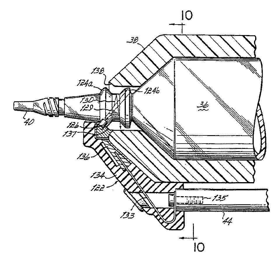
图9是空气探测模块就位时装于压力套中的注射管的局部横截面图,显示了空气探测模块的内部结构及其与注射管嘴的相互作用关系;Fig. 9 is a partial cross-sectional view of the injection tube installed in the pressure jacket when the air detection module is in place, showing the internal structure of the air detection module and its interaction with the injection nozzle;
图10是空气探测模块沿图9中的10-10线的视图,其中注射管和压力套拆走;Fig. 10 is a view of the air detection module along line 10-10 in Fig. 9, wherein the injection tube and the pressure sleeve are removed;
图11A是动力头中的模拟电路的电气框图,包括温度控制、空气探测以及手动控制电路;Figure 11A is an electrical block diagram of the analog circuit in the power head, including temperature control, air detection and manual control circuits;
图11B是动力头中的数字控制电路的电气框图,包括中央处理器、监视微控制器、数字状态、控制及界面连接;Figure 11B is an electrical block diagram of the digital control circuit in the power head, including a central processing unit, a monitoring microcontroller, digital status, control and interface connections;
图11C是动力头、动力组、控制台中的中央处理器、监视微控制器及其相互连接关系的电气框图;Fig. 11C is the electrical block diagram of power head, power pack, central processing unit in the console, monitoring microcontroller and their interconnection;
图12显示了动力头的中央处理器中的加热垫的温度控制算法;Figure 12 shows the temperature control algorithm of the heating pad in the central processing unit of the power head;
图13A显示了由动力头微处理器中的用于控制注射器操作的软件确定的倾斜范围,图13B显示了动力头的显示器中的元素,以及当动力头位于第一倾斜角度时显示器的典型输出模式,以及图13C显示了与图13B类似的当动力头位于第二倾斜角度时显示器输出的相同信息。Figure 13A shows the tilt range determined by the software in the powerhead microprocessor used to control the operation of the injector, and Figure 13B shows the elements in the powerhead's display and the typical output of the display when the powerhead is at a first tilt angle mode, and FIG. 13C shows the same information output by the display similar to FIG. 13B when the power head is at the second tilt angle.
具体实施例的详细说明Detailed Description of Specific Embodiments
请参考图1,一个根据本发明的注射器20包含各种功能部件,例如一个动力头22、一个控制台24以及一个动力组26(安装在一个罩盖下面)。一个注射管36(图2)安装在注射器20上并位于动力头22的面板28中,还有各种控制杆用于向注射管中充液,例如CT、血管造影或其它过程所需的造影剂,之后,该造影剂会在操作者或预编程控制器的监测下注射到一个对象中。Referring to FIG. 1, a
动力头22包含一个手动运动控制杆29用以控制内部驱动电机的运动,以及一个显示器30用以向操作者显示注射器的当前状态和工作参数。控制台24包含一个触摸屏显示器32,其可以被操作者使用而遥控注射器20的操作,还可以用于编制和存储自动控制注射器20操作的程序,之后,在操作者启动注射器后,这些程序可以被注射器自动执行。The
动力头22和控制台24通过电缆(未画出)连接着动力组26。动力组26包含一个注射器电源、用于连接控制台24和动力头22的界面电路以及用于将注射器20与遥控系统,如遥控台、手或脚遥控开关连接的附加电路,或者还包含原始设备制造商(OEM)提供的其它遥控接头,这些遥控接头用于,例如,使注射器20的操作与造影系统X射线的曝光同步。The
动力头22、控制台24和动力组26安装在一个底盘34上,底盘34包含一个支撑着动力头22的支撑臂35,以便于动力头22在检验对象附近定位。然而,也可以采用其它安装方式;例如,控制台24和动力组26可以放在一个台子上或安装在检验室的一个电子仪器架上,而动力头22可以由安装在天花板、地板或墙壁上的支撑臂支撑着。The
现在请参考图2,在操作中,一个注射管36和压力套38安装在动力头22上,这样动力头22内部的电机可以被通电以带动一个活塞37在注射管36的桶中向着和背离注射管的一个排液嘴40移动,从而将液体从注射管36中排出或将液体充入注射管。压力套38用于支撑注射管36的外壁以保护注射管36的壁,以免在注射压力较高时失效。Referring now to FIG. 2, in operation, a
注射管36和压力套38由一种透明塑料制成,操作者可以透过它们看到活塞37的当前位置以及活塞37与排液嘴40之间是否存在液体或空气。这样,如上所述,操作者可以向上倾斜动力头22,从一个液体源将液体充入注射管36并视觉监视充液过程,之后将注射器与通向患者的导管连接起来,从导管和注射管中排出空气并视觉监视注射管中的液位,当空气被排出后,向下倾斜注射器并将液体注射到一个对象中。The
为了方便充液过程以及在向对象注射过程中的其他操作,动力头22包含手动运动控制杆,该装置的形式为可旋转杆29。具体地讲,杆29可以绕着一个位于动力头22中的旋转轴线旋转。当手动运动控制杆29位于它的原始位置时,如图2所示,动力头22中不会产生活塞运动。然而,当手动运动控制杆29向着注射管36旋转时,动力头22中会产生正向的活塞运动,从而将液体或空气从注射管36中排出。另外,当手动运动控制杆29从注射管36旋转开时,动力头22中会产生反向的活塞运动,从而将液体或空气充入注射管36中。手动运动控制杆29的详细结构和操作将在后面通过图6-7C进行解释。To facilitate the priming process and other manipulations during injection into a subject, the
为确保注射到对象中的液体保持在体温左右,一个加热垫42顶靠着压力套38的外壁安装着。加热垫42包含一个电热器,其产生热量以调节注射管36中的液体的温度。加热垫42(单独显示于图8中)安装在一个支柱44上,支柱44从面板28上伸出并保持加热垫42与压力套38导热接触。To ensure that the fluid injected into the subject remains at around body temperature, a
在动力头22的后端有一个指示灯46(被一个光线散射盖覆盖着),用以显示动力头的状态,如后面详细讨论。At the rear end of the
现在请参考图3,以解释动力头的内部结构。Please refer now to Figure 3 to explain the internal structure of the power head.
动力头22由两个外部半壳47a和47b构成。半壳47a和47b配合起来形成动力头22的完整容壳。上半壳47a包含一个用于使显示器30显示出来的开孔、指示灯46以及用于支撑一个轴48的支撑面,手动运动控制杆29即附着到该轴48上。安装在上半壳47a内部的手动运动控制杆的详细结构将在后面进一步详细讨论。The
下半壳47b包含一个开孔,一个旋钮49通过该开孔连接到内部传动链上。可以用手旋转旋钮49以移动活塞传动筒的传动链,从而精确控制传动筒的运动,并且即使有电气故障使得动力头22失效,也能够使动力头运动。下半壳47b上的一个第二开孔51用于使动力头电路板55(见下文)与从加热垫42(见图2,8)和空气探测器附件(见图9,10)引出的电线连接起来。The lower half shell 47b contains an opening through which a knob 49 is connected to the internal drive chain. Knob 49 can be turned by hand to move the drive chain of the piston cylinders, thereby precisely controlling the movement of the cylinders and enabling the powerhead to move even if an electrical failure renders the
下半壳47b上还包含一个安装导轨(位于下半壳47b内的凹槽50的相反侧),用以接收一个固定件52,固定件52则用于将半壳47b安装在一个活节臂上,例如图1和2中所示的臂35。固定件52可以从动力头22的任意一侧插入下半壳47b的安装导轨中,以便于将动力头22安装在一个检验台的任意一侧。一个旋钮53用于将固定件52固定在下半壳47b的安装导轨中。The lower half shell 47b also includes a mounting rail (on the opposite side of the recess 50 in the lower half shell 47b) for receiving a
动力头22的内部结构包含一个电路板55,该电路板上携带着几乎所有的控制动力头22操作的电路。电路板55上值得注意的部件包括磁探测器56a、56b和56c以及标志传感器58。磁探测器56a、56b、56c和标志传感器58的功能将在下文中详细解释。The internal structure of the
在动力头22中的电路板55的下面安装着传动链60,用以移动活塞传动筒62。传动链60包含一个由电路板55控制的旋转电机63,该电机(通过一个齿轮箱68)带动一个传动齿轮64旋转。传动齿轮64与一个主齿轮65啮合,主齿轮65又带动一个滚珠丝杠66旋转。活塞传动筒62安装在一个滚珠丝杠螺母67上,滚珠丝杠螺母67可以将滚珠丝杠66的旋转运动转换成活塞传动筒62进出动力头22的直线移动,从而使安装在动力头22上的一个注射管36的活塞37(图2)移动。旋钮49连接到传动齿轮64的轴线上,从而可以用手旋转传动链60并移动活塞传动筒。Below the circuit board 55 in the
传动链60的这些元件安装在一个传动壳69上。当上下半壳47a和47b围绕着传动壳69组装在一起后,传动壳69的前表面70是暴露在外的。注射器的面板28固定到前表面70上,从而使得一个注射管可以安装到传动壳69的前表面70上,以使活塞传动筒62可以啮合并移动活塞37。These elements of the drive chain 60 are mounted on a
面板28利用一个铰销72而铰接在前表面70上。当面板28通过铰销72连接在前表面70上后,面板28可以沿着方向73在铰销72上旋转,并且可以沿着铰销在方向74上移动一段有限的距离。这种旋转和移动的组合使得面板28可以与前表面70咬合和脱离,从而可以将注射管向面板28安装和取走,并同时将注射管活塞与活塞传动筒62连接或脱开。
当面板28完全咬合在前表面70上后,面板28上的翼板75a和75b会分别配合在前表面70的槽76a和76b内。这种配合关系如图4所示。如需将面板28与前表面70脱离,可使面板28沿方向74移动以将翼板75a和75b从槽76a和76b中脱开,从而使面板28能够绕着铰销72沿方向73(图3)旋转,这样可以接触到安装在面板28上的注射管。When the
为了便于沿方向74移动面板28,有一个凸轮杆78安装在传动壳69上并位于面板28与传动壳69之间。凸轮杆78固定在一个安装在传动壳69中的凸轮杆轴79上并可旋转该凸轮杆轴。凸轮杆78包含一个伸向面板28的圆钮81。圆钮81与一个成形于面板28内表面上的槽道80配合(见图4),这样,凸轮杆78的旋转可以带动圆钮81,以使面板28沿方向74移动,从而使翼板75a和75b与槽76a和76b咬合或脱开。To facilitate movement of the
一个标志垫片82安装在凸轮杆轴79上并被一个螺母83保持就位。标志垫片82和凸轮杆78上的连接着凸轮杆轴79的孔是键连接的,这样,凸轮杆78和标志垫片82可以彼此相对与对方保持方位一致。由于标志垫片82和凸轮杆78均通过键连接在轴79上,因此旋转凸轮杆78将带动轴79和标志垫片82旋转。标志表面84从标志垫片82上伸出;因凸轮杆78旋转引起的标志表面的运动将如后文所述被检测到并用于确定面板28是否与动力头22咬合。An
现在请参考图3和4,当动力头22位于图4所示位置时,标志垫片82位于电路板55上的标志传感器58的对面。标志传感器58产生一个光束,当标志表面84位于传感器58对面时,光束将反射回去并被传感器58探测到。凸轮杆78和标志垫片82键连接在轴79上,从而使得只有当凸轮杆78位于图4所示位置时标志表面84才能在传感器58对面旋转,在图4所示位置,凸轮杆78使面板28移动到与传动壳69的前表面70咬合的位置。这样,当标志表面84位于传感器58的对面时,这意味着面板位于关闭位置,已准备好可以充液或注射。Referring now to FIGS. 3 and 4 , when the
动力头22包含一个安全锁,用以在活塞传动筒62不是完全缩回的时候防止凸轮杆78旋转到一个脱开位置。具体地讲,请参考图4,一个弹簧加载的锁板86安装在传动壳69上,其安装方式使得它可以沿方向90平移运动。螺钉87将锁板86保持在传动壳69上并允许这种平移运动。弹簧88连接在锁板86与传动壳69之间,以提供力,使锁板86有向传动壳69的前表面70滑动进入图4所示位置的趋势。
当锁板86位于这个最前方位置上时,锁板86的前角部89邻近于标志垫片82,如图4所示。其结果是,标志垫片82上的刻槽85(见图3)与锁板86的前角部89之间的干涉作用可以防止标志垫片82(以及凸轮杆78)离开图4所示的咬合位置旋转到一个脱离位置上,在该脱离位置,面板与传动壳69的前表面70脱离并可以从前表面70旋开以更换一个注射管。然而,当锁板沿着方向90反向滑动时(抵抗着弹簧88的力),前角部89与刻槽85之间的干涉消除,使得凸轮杆78可以向着一个脱离位置旋转。When the
一个位于活塞传动筒62上的接头91咬合着锁板86,这样,当活塞传动筒61从面板28处撤回到一个最后方位置时,接头91会咬合锁板86并将锁板移动到它的后方位置上。然而,当活塞传动筒62从这个位置正向移动时,弹簧88的力将带动锁板移动到它的前方位置上。这样,作为活塞传动筒62、锁板86和标志垫片82之间相互作用的结果,面板28不能沿方向74平移运动,即从传动壳69的前表面70脱离,除非活塞传动筒62位于其最后方位置上。这种联锁功能可以在活塞传动筒62伸入一个安装在面板28上的注射管的内部时,防止操作者试图将面板28从面板70上脱开。A joint 91 on the
现在请参考图4和5,图中显示了三个磁导体94a、94b和94c。这些导体由高导磁性、低顽磁性的材料,例如钢或铁制成,并且插入传动壳69的前表面70上的孔中。Referring now to Figures 4 and 5, three
每个面板20上可以装有一些永磁体,这些永磁体插这样的位置上,即这些位置与三个磁导体94a、94b和94c的位置对齐。可以装有三个、两个、一个或没有永磁体,而且磁体可以以它们的北极或南极面对磁导体94a、94b和94c。Each
图4所示的面板28中包含两个永磁体96a和96b,它们分别与磁导体94a和94b对齐。然而,图4所示的面板28中没有磁体位于磁导体94c对面。
在图3和4所示的动力头22中可以采个多种不同的面板28。可以采用不同的面板28以适应于动力头22采用不同类型的注射管36;例如,一个面板的尺寸适用于低容量的儿科注射管,而另一个面板的尺寸适用于成人容量的注射管。同空着购买的注射管相比,预充液注射管可以具有不同的尺寸或规格。需要不同的面板28以容纳这些不同尺寸的注射管。A variety of
电路板55上的电路需要能够探测到是哪个面板安装在动力头22上。首先,控制电路必须确定是否有一个空气探测模块附加在面板上。此外,不同类型的注射管36的长度可以不同,在这种情况下,在确定活塞传动筒的运行终点位置并计算注射管36中的液体体积时,动力头22必须能够补偿这种长度变化。同样,在活塞传动筒62的运行速度相同的情况下,不同直径的注射管的流速不同;在将所需流速换算成活塞传动筒62的运行速度时,控制电路必须补偿这种差别。The circuitry on the circuit board 55 needs to be able to detect which panel is mounted on the
出于识别的目的,每个不同的面板28上安装着的与传动壳69的前表面70中的磁导体94a、94b和94c相对齐的永磁体的组合方式均是唯一的。具体地讲,图4所示的面板中包含两个永磁体,它们分别面对着磁导体94a和94b。另一个面板上可以只有一个永磁体,其面对着磁导体94b。第三个面板上可以有三个永磁体,它们分别面对着所有磁导体94a、94b和94c。在每个位置上可以没有磁体,也可以改变磁体极性,这样,这些磁体可以一共产生27(33)种磁体组合方式,因此,通过这种方式可以使27个不同的面板具有唯一的标识。For identification purposes, the combination of permanent magnets mounted in alignment with the
为了探测面板中永磁体的数量和位置,动力头22中的控制电路包含磁探测器56a、56b和56c,它们可以是,例如霍尔效应传感器(或者,也可以是舌簧开关)。这三个磁探测器56a、56b和56c位于电路板55的一个边缘处,并对准三个磁导体94的内端,比较图4和5可以看到这点。通常,传动壳69由非磁性材料,如铝制成。这样,永磁体96a和96b产生的磁场可以通过导磁性磁导体94a、94b和94c,并进入磁探测器56a、56b和56c附近,从而可以通过电路板55在远离面板28处探测到面板28上是否存在永磁体。To detect the number and position of the permanent magnets in the panel, the control circuitry in the
这些磁导体通过将磁场从面板28上的永磁体传导到位于电路板55上的远距离探测器上,从而显著降低了动力头22上的电子装置部分的费用。虽然可以购买到独立的磁探测器并将它们安装到传动壳69的前表面70上,但独立的磁探测器通常要比可安装到印刷电路板上的探测器昂贵。此外,采用独立的磁探测器需要制造多个分开的电路板和/或线束并将它们安装在动力头的容壳中,再通过适宜的电缆连接到主电路板上,因此,同本实施例中将探测器安装在主电路板上的结构相比,前面的结构会使得动力头22的制造更加复杂、昂贵和耗时。因此,采用磁导体94a、94b和94c可以显著降低动力头22的制造费用。These magnetic conductors significantly reduce the cost of the electronics portion of the
请参考图6,现在可以解释手动运动控制杆。如前面所示,手动运动控制杆29沿正向或反向旋转分别表示操作者希望将活塞传动筒正向或反向移动。为确定杆29的旋转方向和角度,有一个旋转电位计98连接着杆29的轴48,这样杆29的旋转将带动电位计98内部的一个电刷旋转,从而产生一个变化着的电阻,该电阻可以被动力头控制电路检测。Referring to Figure 6, the manual motion control lever can now be explained. As previously indicated, rotation of the manual
如前面所示,当控制杆29沿方向99正向旋转时,控制电路会根据电位计98产生的电信号而检测到这个旋转动作,从而使活塞的传动筒62正向移动,即从动力头的容壳向外移动,移动速度与控制杆29从图6所示原始位置偏移的角度成正比。另一方面,当控制杆29沿方向100反向旋转时,控制电路会根据电位计98产生的电信号而检测到这个旋转动作,从而使活塞的传动筒62反向移动,即移入动力头的容壳,移动速度与控制杆29从图6所示原始位置偏移的角度成正比。As shown above, when the
图6显示了两个复位弹簧102a和102b,它们顶靠着轴48并产生力矩使轴48有返回图6所示原始位置的趋势。此外,还显示了组合标志/接触板104,其环绕着轴48并可以与复位弹簧102a和102b接触。复位弹簧102a和102b与标志/接触板104接触时,可以使它们之间形成电气连接,并施加弹簧力矩使轴48有向原始位置返回的趋势。还可以看到一个止动弹簧106,其功能将在下文中详细解释。还有一个标志传感器108,其为光学探测器,可产生脉冲光线并使脉冲光线穿过一个间隙,检测间隙的另一侧接收到的脉冲光线并产生一个数字信号,以显示间隙是否被堵住而阻止了光学的传输。FIG. 6 shows two
现在请参考图6、7A和7B,可以看到,当杆29位于原始位置时(见图6和7A),标志/接触板104位于复位弹簧102a和102b之间的等距位置上,两个复位弹簧向杆29施加方向相反的力矩,以使该杆29有被保持在这个原始位置的趋势,在这个位置上,标志/接触板104的标志板105位于标志传感器108中,使标志传感器108产生一个数字信号,以显示杆29位于其原始位置上。在这种情况下,动力头22的控制电路可以判断出,不需要通过手动运动控制杆使活塞运动。Referring now to Figures 6, 7A and 7B, it can be seen that when the
然而,当杆29从其原始位置旋转开后,例如到达图7B所示位置时,标志板105移到标志传感器108形成的间隙的外面,从而使标志传感器108产生一个数字信号,以显示杆29离开了其原始位置。在这种情况下,控制电路可以读取电位计98产生的电信号,以确定杆29的位置并使活塞传动筒产生适宜的运动。However, when the
如前面所示,活塞传动筒的移动速度与杆29偏移开原始位置的程度成正比。同时,随着杆29从原始位置旋转并增大夹角,复位弹簧102a和102b的机械结构可以确保有一个复位力矩施加到杆29上。根据弹簧102a和102b的刚度以及杆29的运动范围,这种复位力矩可以在所有偏移角度内几乎相等,或者可以随着偏移角度的增大而增大或减小。如果复位力矩随着偏移角度的增大而增大的话,那么可以使操作者获得附加的活塞速度反馈功能。As previously indicated, the speed at which the piston cylinder moves is proportional to the extent to which
如图7B所示,当杆29沿反向旋转并增大夹角时,最终会使标志板105接触到止动弹簧106并使止动弹簧106开始与复位弹簧102a和102b一起弯曲。这将导致施加的力矩增大,并被操作者觉察到,从而作为手动运动控制杆旋转中的一个“止动器”。As shown in FIG. 7B , when the
在向一个注射管充液时,有一个理想的最大速度,在这个速度上,由于液体处于非层流状态,因此液体可以抽入注射管中而不形成气泡。在提高注射管的充液速度时,一旦达到了这个理想速度,操作者应当得到反馈信号,以使注射管在理想速度充液。止动弹簧106的目的是向操作者提供杆29偏移角度的机械式反馈信号,此位置对应于理想充液速度。更具体地讲,当杆29的旋转使得标志板105与止动弹簧106接触时,动力头22的控制电路可以确认使活塞传动筒在理想充液速度附近移动。这样,希望在理想速度附近充液的操作者可以旋转杆29直至增加的止动力矩可以觉察到,然后可以将杆29保持在止动位置而进行充液。When filling a syringe, there is an ideal maximum velocity at which liquid can be drawn into the syringe without the formation of air bubbles due to the non-laminar flow of the liquid. When increasing the filling speed of the syringe, once this ideal speed is reached, the operator should get a feedback signal to make the syringe fill at the desired speed. The purpose of the
复位弹簧102、标志/接触板104和止动弹簧106不仅机械式运行以向操作者提供机械式反馈信号,而且还作为动力头22的控制电路中的电气元件。具体地讲,请参考图7C,这些元件中的每一个均是电路中的电路元件,以产生动力头22的控制电路所需的数字控制信号。The return spring 102 , flag/
从图7C可以看到,复位弹簧102a和102b以及二者之间的标志/接触板104与一个电阻110串联在一个数字式+5伏电源与地极之间。一个信号线115从电阻110与复位弹簧102a之间伸出并携带着一个逻辑电压信号,用以显示在复位弹簧102a和102b与标志/接触板104之间是否有电气接触。在正常状态下,有一个从这个线路到地极的电气通路,以保持线115上的电压处于低阶。然而,如果弹簧102a和102b中的任何一个失效并且不再与标志/接触板104接触了,那么这种电气触点就断开了,而线路115上的电压会升到一个高阶上,以显示一个复位弹簧失效。虽然只有在两个复位弹簧均失效时杆29才会无意中从其原始位置偏移开,但只要有一个复位弹簧失效就可以通过监视线路115上的电压而探测到。一旦探测到这种失效,会向操作者发出一个警告,或者可以使手动运动控制杆停止工作。As can be seen in Figure 7C, the return springs 102a and 102b with the flag/
与前面的方式类似,止动弹簧106构成一个电气触点并与一个电阻111串联,一个止动信号线116从电阻111与止动弹簧106之间伸出。如果控制杆29没有旋转到止动弹簧中,线路116上的电压会升到一个高阶上,以显示控制杆29不在止动位置。然而,如果控制杆29的旋转使得标志板105与止动弹簧106接触时,线路116上的电压会降到低阶,以显示控制杆29旋转到了止动位置。线路116上的信号可以用于多种途径。例如,该信号可以用于校正手动运动控制杆,以使杆在止动位置的旋转角度对应于理想充液速度。或者,该信号可以用于防止活塞传动筒以一个高于理想充液速度的速度反向运动。最后,该信号可以用于建立一个运动“死区”,在此活塞传动筒将以理想充液速度移动,同时又使控制杆能够旋转超过“死区”,以产生更快的反向速度。Similar to the previous method, the
图7C中还显示了标志传感器108的电路详图;通过一个电阻113可以使一个发光二极管被一个偏流充电;当光线穿过传感器108中的间隙并且射到传感器108中的光电晶体管的基部时,光电晶体管会使一个电流通过电阻112,从而使线路117上的原位信号降到一个低电压值,以显示控制杆29不在其原始位置上。否则,如果光线不能到达传感器108中的光电晶体管的基部,就不会有电流流过电阻112而且线路117上的原位信号会升到一个高电压值,以显示控制杆29在其原始位置上。因此,动力头22的控制电路可以利用线路117上的信号以确定是否要终止活塞传动筒的运动。Also shown in Figure 7C is a circuit detail of the sign sensor 108; a light emitting diode can be charged with a bias current through a resistor 113; The phototransistor causes a current to pass through resistor 112, thereby dropping the home signal on
现在请参考图8,动力头22中采用的根据本发明的加热垫42包含一个环形塑料段118和一个模塑成形出的塑料基座。塑料段118包含一个由电阻丝制成的电热丝120,当一个电流从一个适宜的电源开始流过电热丝时,电热丝可以产生热量。电热丝120伸展通过环形塑料段118的整个区域,当加热垫42安装到支柱44上时,如图2所示,电热丝120将与压力套38接触,电热丝120两端连接着包围在绝缘电缆117中的电线,绝缘电缆117可以通过开孔51(图3)而插入动力头22的控制电路中,如图2所示。当电流从动力头开始经过电缆117中的电线并流经电热丝120时,电热丝120将均匀地产生热量,以加热压力套38中的注射管中的液体。Referring now to FIG. 8, the
环形段118可以是不透明的,或者也可以是透明或半透明的。如果环形段118是透明的,电热丝120可以被看到(象汽车除霜器或纱窗中的那样),这样,操作者可以通过环形段、压力套38和注射管壁看到注射管中的液体。这样有利于在使用中使操作者的主要视线到达注射管内部,而在其它情况下注射管会被加热垫挡住。
加热垫的基座119由软塑料制成,并且模塑成形在一个弹性骨架外部。弹性骨架成形为盘121的形式,盘121的尺寸使之与支柱44略有干涉。其结果是,加热垫42可以压紧配合在支柱44上以实现普通的安装与拆卸(例如用于清洁)。The
现在请参考图9和10,以解释整体式空气探测系统。空气探测模块122安装在支柱44的端部,并且成形为包裹在压力套38的远端部分周围并与一个环绕着注射管36的排液颈并向外伸出的套环124a相接触。在与套环124a的接触点处,空气探测模块122包含一个光源126和一个光传感器127。光传感器127是一个可以购买到的电路,其包含一个传感器127和一个振荡器,振荡器可以产生一个触发信号,以显示应在何时向光源126通电以产生一个光束。传感器127的输出为数字信号,以显示在光源被触发后是否有光束被传感器接收。Please refer now to Figures 9 and 10 for an explanation of the integrated air detection system.
图9和10显示了光源126发出的光束的轨迹。光源126包含一个整体式聚焦透镜,而位于注射管36的排液颈上的套环124a则构成一个第二聚焦透镜。这些透镜协同工作,以使光源126发出的光线沿着轨迹129向着位于注射管36的排液颈上的套环124b传输。套环124b的内部形状构成一个角部反射器,这样,从光源126发出的光线照射在套环124b上后,会被向着传感器127反射。9 and 10 show the trajectory of the light beam emitted by the
这种结构的结果是,当注射管36的颈部充满液体时,从光源126发出的光线会通过注射管颈部中的轨迹并被反射而返回到光传感器127,如图9和10中的轨迹129所示。因此,在这种状况下,传感器127将产生一个用以显示接收到光线的数字信号,这就表明在注射管颈部没有空气。(光源126与套环124a处的透镜的焦距之和大于光线沿着轨迹129传输的距离,即大于套环124a与套环124b之间距离的两倍)。As a result of this configuration, when the neck of the
然而,如果注射管颈部含有空气或气泡,光线在气/液或气/注射管边界的衍射会使得光线从图9和10中的轨迹129偏移开。具体地讲,射入注射管36颈部的光线将沿着图9中所示轨迹130或图10中所示轨迹131传输。在任何一种情况下,气泡的存在将阻止从光源126发出的光线在注射管颈部反射到光传感器127,从而使得光传感器产生一个用以显示未能接收到光线的信号,这就表明在注射管颈部存有空气。However, if the syringe neck contains air or air bubbles, diffraction of light at the gas/liquid or gas/syringe boundary will cause the light to deviate from
为了获得稳定的可重复性结果,空气探测模块122的结构可以确保光源126、光传感器127与注射管36的套环124a的表明紧密接触。具体地讲,空气探测模块122具有一个弹簧金属制成的内骨架133,该内骨架通过模塑成形的一个软弹性塑料134包裹。弹簧金属骨架133的一端通过螺钉135(其可以通过包裹塑料134中的空间触及)安装在支柱44上。骨架133的另一端支撑着空气探测模块,空气探测模块中包含一个硬塑料模塑件136,该模塑件136支撑着光源126和光传感器127。模塑件136中包含一个倾斜段137,倾斜段137的尺寸适于压力套38的开口处的倒角138中。倾斜段137与倒角138的相互作用可以确保将光源126和光传感器127相对于压力套38精确定位。In order to obtain stable and repeatable results, the structure of the
注射管36的颈部的尺寸适合于稍有干涉地配合,这样,当注射管36插入压力套38后,套环124a会接触并使空气探测模块122稍微偏移,从而弯曲弹簧骨架133并使光源126和光传感器127向注射管36的套环124a施加一个均匀的力。这个施加的力可以确保光源126发出的光线以良好的传输途径进入注射管36的颈部,再从注射管36的颈部进入光传感器127。The neck of the
现在请转向图11A,以解释空气探测模块以及其他模拟电气系统的电路详图。具体地讲,在空气探测模块中采用了一个可以购买到的同步探测电路140,该电路140中包含一个可以在线路141上产生触发脉冲的内部振荡器,而且电路140可以在每个触发脉冲的同时探测线路142上的用于显示光线被光传感器127接收的信号。只要在每个触发脉冲的同时探测到光线,就会在线路143上产生一个高阶信号。在采用了根据本发明的电路140的情况下,线路143上的信号显示出在注射管36的颈部是否有空气被探测到。Turn now to FIG. 11A to explain the circuit details of the air detection module and other simulated electrical systems. Specifically, a commercially available synchronous detection circuit 140 is used in the air detection module, which includes an internal oscillator that can generate a trigger pulse on line 141, and the circuit 140 can be activated at the start of each trigger pulse. Simultaneously, a signal on line 142 indicating light received by
动力头22的控制电路可以控制施加到空气探测器上的光线强度,以控制探测器的灵敏度。为此,控制电路在线路145上产生了一个脉冲宽度调节(PWM)数字信号。该PWM信号被一个低通滤波器146滤波以产生一个模拟控制电压,用以控制可调调节器147在线路148上产生电路140的电源信号。The control circuit of the
作为对线路141上的触发信号的响应,一个PNP光晶体管149接通,从而导致线路148上的电源信号给光源126通电。这样,线路148上的电源信号的电压直接影响光源126产生的光线的强度。In response to the trigger signal on line 141 , a PNP phototransistor 149 turns on, causing the power signal on line 148 to energize
为了使控制电路能够监视空气探测电路140可能出现的故障,线路141上的触发信号通过一个光隔离器150中的发光二极管连接到PNP光晶体管149的基极。这样,一旦启动了触发信号,光隔离器150中的光晶体管就会接通,从而导致线路151中的电压变为低阶。这样,如果同步空气探测电路140正常工作并产生周期性触发信号,则线路151中会出现脉冲,这些脉冲可以被控制电路探测到,以确定电路140中的振荡器是正常工作的。In order for the control circuit to monitor possible malfunctions of the air detection circuit 140, the trigger signal on line 141 is connected to the base of a PNP phototransistor 149 through an LED in an optoisolator 150. Thus, once the trigger signal is activated, the phototransistor in optoisolator 150 is turned on, causing the voltage on line 151 to go low. Thus, if the synchronous air detection circuit 140 is functioning properly and generates a periodic trigger signal, pulses will appear on line 151 which can be detected by the control circuit to determine that the oscillator in circuit 140 is functioning properly.
图11A还显示了模拟一数字(A/D)转换器152,其装于动力头控制电路中,用以将各个电气元件产生的模拟信号数字化。例如,电位计98(见图6)连接着充液/排液杆29的轴48。该电位计的电刷连接着一个信号线154,信号线154携带着用于显示充液/排液杆轴48的旋转位置的模拟电压。电位计的相反端部分别连接着一个参考电压和地极,这样,线路154上的电压位于这两个极限之间并取决于充液/排液杆29的旋转位置。线路154连接着A/D转换器152,而转换器152可以将线路154上的模拟电压转换成一个数字信号,该数字信号位于一个“SPI”串行接口总线156上,以供CPU(见图11B)使用,这样,CPU可以确定充液/排液杆29的旋转位置并作出反应。FIG. 11A also shows an analog-to-digital (A/D) converter 152, which is installed in the power head control circuit to digitize the analog signals generated by various electrical components. For example, a potentiometer 98 (see FIG. 6 ) is connected to the shaft 48 of the fill/
空气模拟电压也要输入A/D转换器152中。具体地讲,一个单片式加速计采用了一个倾角传感器158的形式,以在线路159上产生一个模拟电压,以显示传感器158的倾斜角度。(一种适用于这种用途的单片式加速计可以从马萨诸塞州的Analog Devices ofNorwood公司购买,货号为ADXL05AH。)传感器158安装在电路板55上并用于产生输出电压,以显示动力头22相对于地球重力方向的倾斜角度。这个模拟倾角信号被转换并输入CPU以供使用,如下文所述,以控制动力头22的显示器和其他操作部件。The air analog voltage is also input into the A/D converter 152 . Specifically, a monolithic accelerometer takes the form of an inclination sensor 158 to generate an analog voltage on line 159 to indicate the inclination angle of sensor 158 . (A monolithic accelerometer suitable for this purpose is available from Analog Devices of Norwood, Mass., part number ADXL05AH.) Sensor 158 is mounted on circuit board 55 and is used to generate an output voltage to indicate the relative The angle of inclination in the direction of Earth's gravity. This analog tilt signal is converted and input to the CPU for use, as described below, to control the display and other operating components of the
第三个模拟信号由一个线性电位计160产生,线性电位计160的电刷机械式连接着活塞传动筒62,并根据活塞传动筒的运动而运动。这样,在线路161上的电刷电压是一个代表传动筒位置的模拟信号,该位置在最前方位置与最后方位置之间。这个信号被转换并输入CPU以供使用,以确定传动筒的位置以及注射管剩余容量等其他参数。The third analog signal is generated by a linear potentiometer 160 whose brushes are mechanically connected to the
两个附加的模拟信号由热敏电阻163a和163b产生,二者分别与偏压电阻串联以在线路164a和164b上产生反映热敏电阻温度的信号。从热敏电阻上获得的温度测量值用于控制施加到加热垫上的电能,而加热垫用于加热注射管36中的液体。具体地讲,施加到注射管上的加热功率随着外界温度而变化,而外界温度由热敏电阻163a和163b测量,这样可以保持液体处于目标温度,例如30摄氏度。Two additional analog signals are generated by thermistors 163a and 163b, respectively, in series with biasing resistors to produce signals on lines 164a and 164b reflecting the thermistor temperature. The temperature measurement obtained from the thermistor is used to control the electrical power applied to the heating pad which is used to heat the liquid in the
热敏电阻163a和163b是彼此重复的,也就是说,它们测量的温度相同并且它们的测量值要相互比较以确保几乎相等。其结果是,如果某一个热敏电阻失效了,那么可以从两个热敏电阻测量出的温度之间出现差别而判断出来,以此防止对温度控制的失误。Thermistors 163a and 163b are duplicates of each other, that is, they measure the same temperature and their measurements are compared to each other to ensure they are nearly equal. As a result, if a thermistor fails, it can be judged from the difference between the temperatures measured by the two thermistors, thereby preventing errors in temperature control.
热敏电阻163a和163b可以在动力头22内部安装在电路板55上。或者,热敏电阻163a和163b也可以安装在容器外面,以确保更精确的温度读数,或者也可以提供全部两种可能以供选择,即装有内置热敏电阻,而如果用于替换的外置热敏电阻连接到了动力头22上,则内置热敏电阻停止工作。Thermistors 163 a and 163 b may be mounted on circuit board 55 inside
如上所述,采用了热敏电阻163a和163b,动力头22可以控制通过加热垫42施加到注射管36上的加热功率。为实现这个功能,CPU(见图11B)在线路166上产生一个脉冲宽度调节(PWM)控制信号,用以控制施加到加热垫电热丝120上的加热功率。具体地讲,线路166上的PWM控制信号被一个低通滤波器167滤波以产生一个用于控制可调调节器168的模拟控制信号。调节器168输出到线路169上的信号是一个可变电压,该电压施加到加热垫电热丝120上,以使电热丝120产生热量。Using thermistors 163a and 163b,
一个为施加在电热丝120上的电压滤波并调节的测量放大器170在线路171产生一个模拟输出信号,该信号与施加在电热丝120上的电压成正比。A sense amplifier 170 which filters and conditions the voltage applied to the heating wire 120 produces an analog output signal on line 171 which is proportional to the voltage applied to the heating wire 120 .
一个检测电阻173与电热丝120串联,以使电热丝120中的电流流过检测电阻173,在检测电阻上产生的电压与流过电热丝120的电流成正比。检测电阻的电阻远小于电热丝120的电阻,这样,检测电阻173上的小的压降远小于电热丝120上的压降。A detection resistor 173 is connected in series with the heating wire 120 so that the current in the heating wire 120 flows through the detection resistor 173 , and the voltage generated on the detection resistor is proportional to the current flowing through the heating wire 120 . The resistance of the detection resistor is much smaller than the resistance of the heating wire 120 , so the small voltage drop across the detection resistor 173 is much smaller than the voltage drop across the heating wire 120 .
检测电阻173上的压降被一个增益/滤波电路172放大并滤波,从而在线路174上产生一个模拟电压,该电压与流过电热丝120的电流成正比。The voltage drop across sense resistor 173 is amplified and filtered by a gain/filter circuit 172 to produce an analog voltage on line 174 which is proportional to the current through heating wire 120.
线路171和174连接到A/D转换器152,从而将线路171和174上的电压转换为可供CPU读取的数字信号。这样,CPU可以确定出电热丝120中的电流和压降,并利用这些数值决定电热丝120的输出热量。这样使得CPU可以对加热垫的输出热量进行闭环控制,如下文中结合图12所作讨论。Lines 171 and 174 are connected to A/D converter 152, which converts the voltage on lines 171 and 174 into digital signals that can be read by the CPU. In this way, the CPU can determine the current and voltage drop in the heating wire 120 , and use these values to determine the output heat of the heating wire 120 . This allows the CPU to perform closed-loop control of the heat output of the heating pad, as discussed below in conjunction with FIG. 12 .
现在请参考图11B,以理解动力头22的CPU的连接方式。CPU175可以是一个68332微处理器,可从摩托罗拉(Motorola)公司购买到,CPU 175控制着数据和地址总线176,后者将CPU 175连接到随机存取存储器(RAM)178和一个快擦写存储器177。CPU 175还控制着一个SPI串行接口总线156,用于与A/D转换器152、显示器30和一个监视微控制器192进行通讯。CPU 175还包含一个RS-422串口179,用以将CPU 175连接到动力组(见图11C)。Please refer now to FIG. 11B to understand how the CPU of the
CPU 175包含一组数字数据输入线,以监视动力头22的操作。具体地讲,CPU 175接收线路116上的止动信号、线路115上的安全信号和线路117上的原位信号,以使CPU 175接收到有关前面所述的手动运动控制杆的操作状态的输入信号。CPU 175还接收线路143上的气泡信号,这样,CPU 175可以探测到注射管颈部的空气并采取适宜的行动,此外,CPU 175还接收线路151上的气泡探测振荡器信号,如前所述,用以确认空气探测模块122中的振荡器是否正常工作。此外,CPU 175还接收标志传感器58的输出信号,这样,CPU 175可以确定面板是否被锁紧在动力头22上。此外,CPU 175还接收从三个磁探测器56a、56b和56c发出的数字信号,这些信号可以显示若干可用的面板中的哪一个安装在动力头22上了,以使CPU 175随之调整它的操作。
CPU 175还接收并联旋转编码器182发出的数字信号,编码器182在线路183a和183b上产生脉冲信号,用以显示活塞传动链的旋转情况。这些脉冲被CPU 175使用,以确定活塞传动筒的运动。线路183a和183b还连接着动力组(见图11C),这样,动力组的CPU可以通过为编码器的脉冲计数并将接收到的脉冲速率与所需速率比较,从而闭环控制活塞运动。在美国专利No.4,812,724中提出了一种闭环控制法,该专利整体结合在此作为参考。The
CPU 175还产生多个数字控制信号,包括前面提到的那些,例如,线路145上的气泡探测器电源PWM信号、线路166上的加热垫电源PWM信号,这两个信号都被CPU 175进行了脉冲宽度调制,以产生所需的电源级别。CPU 175还在线路187上产生输出信号,以点燃指示灯46(图2)中的发光二极管,指示灯46用以显示注射器的工作状态。输出到SPI串行接口总线156上的附加信号用于控制显示器30。The
CPU 175利用前面所述的输入和输出信号通过软件实现对动力头22的基本控制,软件驻留在CPU 175中或从RAM 178读取。如前所述,CPU 175还通过SPI串行接口总线156连接着一个微控制器192,微控制器192用作一个监视器,以监视CPU 175的工作,确保没有软件或硬件故障。(微控制器可以是一个单片式微控制器,可以从Microchip Technologies公司购买到,货号为no.PIC16C63)微控制器192通过总线156接收用于显示CPU 175工作状态的信号,以完成它的这种功能。The
具体地讲,CPU 175通过总线156显示CPU 175的工作状态,即,CPU 175是否要求活塞运动、所要求的运动是否响应于手动或自动(程序)控制、以及其它可能的特殊信息,例如所要求的运动速度等。监视微控制器192读取总线156上的这些状态信息,并将这些信息与动力头22传来的重要数字输入信号进行比较,以确保它们之间相互吻合。Specifically, the
例如,微控制器192接收线路115上的安全信号和线路117上的原位信号。如果这些信号显示出手动控制杆位于原始位置,则CPU175不会在手动控制杆下产生运动。如果一个弹簧失效(将被线路115上的信号显示出),这将会在CPU 175的状态中显示出来。这样,在这种状态下,微控制器192从总线156上读取信息,以确保CPU 175不会作出与手动控制杆发出的信号不相容的动作。For example,
作为第二个例子,微控制器192接收编码器182输出到线路183a和183b上的信号。微控制器192检测这些信号以确定活塞传动筒是否在移动,从而确保只在CPU 175的状态显示传动筒应该移动时,传动筒才能移动,而在其它状态则不能移动。此外,在这个方面,应注意的是,微控制器192接收门标志传感器58发出的门标志信号。如果该信号指示动力头22的门没有处于锁紧位置,CPU 175不能要求活塞传动筒动作,而微控制器192将通过检测没有脉冲从编码器182发出以确定这一点。As a second example,
现在请参考图11C,以进一步理解动力头22、动力组26和控制台24的相互作用关系。具体地讲,动力头22、动力组26和控制台24中均分别包含一个CPU 175、192、194。这些CPU通过外部接口的相互作用而实现对注射器的控制。例如,活塞传动筒可以通过动力头22上的杆29控制(如前面所讨论),或者也可以由操作者利用控制台24的触摸屏32(采用CPU 194)输入注射器程序再启动注射程序而自动控制。注射参数,例如电机速度和注射量,可以由CPU194产生,CPU 194与动力组的CPU 192通讯,以实现这些程序控制的动作。此外,一个自动注射过程可以利用触摸屏32实现,或者一个注射过程可以采用连接着动力组26的一个手动开关或OEM遥控触发器启动。在任何一种情况下,CPU 192和194中适宜的一个将产生一个启动信号,以开始自动注射。Please refer now to FIG. 11C for a further understanding of the interaction of the
如前所述,动力头的CPU 175与一个监视微控制器192连接,监视微控制器192用于监视CPU 175状态以确保CPU 175的动作与来自动力头22的输出信号一致。同样,CPU 192和194也分别连接着监视微控制器196和198,两个监视微控制器监视着相连CPU 192和194的的动作,以确保一致的无故障动作。As previously mentioned, the
监视微控制器192、196和198之间的通讯与CPU 175、192和194之间的通讯是并行的。具体地讲,三个监视微控制器互相交换它们从相连CPU得到的状态信息,以确保三个CPU处于相同的工作状态,例如,手动运动、自动运动、没有运动等。此外,每个微控制器接收外部输入信号以确保应当发生的状态转换真正发生。这样,微控制器196接收手动或OEM出发信号,以使微控制器196可以确定自动注射过程是何时启动的。微控制器198接收触摸屏32发出的输入信号,这样,它也能够确定自动注射过程是何时启动的。也可以实现其它监视功能,以确保CPU 175、192和194的操作正确且一致。The communication between the monitoring
如上所述,动力头的CPU 175向动力组26传输一个控制信号,请求一个传动筒动作。动力组26中包含电机伺服控制电路,用以在线路200上产生一个适宜的电源信号以驱动电机63并根据线路183上的编码器脉冲而实现对电机运动的闭环控制。As mentioned above, the
在故障状态,各监视微控制器可以通过使硬件停止工作而切断流向电机63的电能,从而停止活塞传动筒的任何运动,该硬件指的是串联在电源线200中的开关202。这种硬件停止工作可以确保各监视微控制器能够防止在故障状态下错误地注射液体。In a fault condition, each monitoring microcontroller can stop any movement of the piston cylinder by cutting off power to the
现在请参考图12,以解释动力头的CPU 175的加热垫的控制功能。为实现加热垫控制,CPU 175首先通过第一和第二热敏电阻163a和163b测量外界温度(第204和206步)。(作为这些步骤中的一部分,CPU 175首先要查询校正表,以将热敏电阻的电压转换成相应温度。)之后,CPU 175将判断这些温度读数是否一致(第208步)。如果不一致,则表示有一个热敏电阻有故障,将产生一个警告信号并使加热垫停止工作(第210步)。Please refer to Fig. 12 now, to explain the control function of the heating pad of
如果热敏电阻的温度读数一致,则CPU 175将运行,即根据测量到的外界温度TAMBIENT确定一个所需加热垫输出功率级POUT(第210步)。一个热模型用于计算为将液体温度保持在37℃所需的功率。功率可以在外界温度0℃至32℃范围内根据这个热模型而变化。当外界温度超过32℃后,加热垫将关闭以防止液体过热。当外界温度低于0℃时,加热垫产生的功率被限制在8瓦,以防止加热垫中的电热丝120过热。一个简单的热模型是线性模型,在线性模型中输出功率由这个公式确定:POUT=B-ATAMBIENT,其中B和A分别是经验计算出的修正和放大系数,而POUT被限制在8瓦。也可以采用其他模型,特别是非线性模型。If the thermistor temperature readings agree, the
为产生所需的输出热能,CPU 175在线路166(图11A)上每个工作周期产生一个PWM信号(第212步)。从所选择的第一个工作周期开始加热注射管中的液体。To generate the desired output thermal energy,
当这个PWM工作周期产生后,CPU 175将从线路171和174上(通过A/D转换器152)读取用于显示施加在电热丝120上的电压和电流(第214和216步)。将这些数值相乘可以得到加热垫的实际输出功率,这个功率将与前面计算的所需输出功率相比较(第218步)。如果当前输出功率与所需功率基本相等,则当前PWM工作周期是正确的,而CPU 175将返回到第204步以重新测量外界温度,从而连续控制加热器输出功率。然而,如果加热器输出功率太大或太小,则CPU 175将先进行第220步,并调节PWM工作周期以根据需要改变输出加热功率(如果太大则缩短工作周期,如果太小则增大工作周期)。之后,CPU 175将返回到第204步,以重新测量外界温度,从而连续控制加热器输出功率。After this PWM duty cycle produces,
这种温度控制法可以补偿因外界温度变化所造成的液体温度变化,从而可以确保对注射管36中的液体进行精确的控制,这样减少因注射液体不在所需温度而造成的对注射对象的热冲击。This temperature control method can compensate the temperature change of the liquid caused by the external temperature change, thereby ensuring accurate control of the liquid in the
现在请参考图13A-13C,以理解可逆显示器的操作。具体地讲,如前所述,CPU 175从倾角传感器158接收一个用于显示动力头22相对于地球重力方向倾斜角度的信号。CPU 175反复从这个信号采样,以确定动力头22相对于地球重力方向(方向122)的倾斜角度。所有可能的旋转角度被划分为六个操作区域,如图13A所示。Please refer now to Figures 13A-13C to understand the operation of the reversible display. Specifically, as previously mentioned, the
区域1为“充液”区;在为注射管充液时,动力头22应位于该区域中的角度上。当动力头22位于区域1中的角度时,或者位于相邻的区域2A或2B中时,动力头允许活塞传动筒沿正向或反向作手动运动,以使操作者可以向注射管充液或在初始充液之后将空气从注射管排出。通过手动运动控制杆可以获得一个大范围的运动速度,从而可以为注射管快速充液。当动力头22在区域1、2A或2B中时,程序控制的注射操作会被禁止;这样,当动力头22位于右上方位置时,操作者不能根据预编程注射方案向对象开始注射。这样可以使误将空气注射到对象中的可能性最小化。Zone 1 is the "fill" zone; the
区域4是“注射”区域。当动力头22倾斜到这个区域后,可以开始程序控制的注射操作。此外,手动运动控制杆29可以用于将活塞传动筒沿正向或反向移动;然而,同区域1、2A或2B相比,由手动运动控制杆产生的运动速度范围相对较窄。这样,可以通过手动运动控制杆实现精确调节控制的液体注射操作。Zone 4 is the "injection" zone. When the
区域3A和3B也可以用于注射。如果一个肥大的患者或其他障碍使得操作者无法将动力头旋转到区域4中的完全向下位置,则动力头可以采用区域3A和3B中的倾斜角度。然而,由于有将空气注射到对象中的可能,因此不提倡在区域3A和3B中操作,这样,在通过控制台触摸屏32进入一个过载软件之前,操作者不能在这两个区域操作。在进入过载软件之前,显示器30将闪烁,而注射器不能进行程序控制的注射操作。一旦进入了过载软件,显示器会停止闪烁,而注射器可以进行程序控制的注射操作。此外,在区域4中,手动运动控制杆19可以用于将活塞传动筒以一个范围很窄的移动速度沿正向或反向移动,这样,可以通过手动运动控制杆实现精确调节控制的液体注射(或排出)操作。Areas 3A and 3B can also be used for injection. If a hypertrophied patient or other obstacle prevents the operator from rotating the powerhead to the fully downward position in zone 4, the powerhead can adopt the tilt angles in zones 3A and 3B. However, operating in areas 3A and 3B is discouraged due to the possibility of injecting air into the subject, and thus the operator cannot operate in these two areas without accessing an overloaded software via the console touch screen 32 . Before entering the overload software, the
上面提到的各种角度区域还涉及到显示方位。具体地讲,如图13B和13C所示,动力头22的显示器30是一个分段式显示器这些段可以被照亮,以显示注射信息,例如已注射量、剩余量以及当前流速。这些段的安排使得上面提到的信息既可以显示于一个第一方位(见图13B),也可以显示于一个第二方位(见图13C)。The various angular areas mentioned above also relate to display orientation. Specifically, as shown in Figures 13B and 13C, the
当动力头22的角度位于区域1、2A或2B中时,动力头22中的CPU 175驱动着显示器30以产生显示方位,使显示器元件采用图13C中所示方式。此外,在区域3A、3B或4中,CPU 175驱动着显示器30以产生图13B中所示显示方位。其结果是,显示器30上显示的信息相对于操作者来说总是向上的,以便于使用显示器。(在图13A所示的各区域之间的边界方向上有一个阻滞功能,以防止无意中停留在区域之间)。When the angle of the
虽然通过对各种实施例的解释使本发明得到说明,而且这些实施例被相当详细地描述过,但本申请人的目的不是将附属权利要求书中的范围限制或在任何方面局限于这些详细说明中。附加的优点和修改可以提供给本技术领域的技术人员。例如,控制电路可以使一个注射压力或充液量与控制杆29相对于原始位置的角位移成正比,而不是使一个速度与旋转程度成正比。气泡探测可以由一个超声波源和连接在注射管颈部的超声波探测器完成,在这种情况下,由于声音在空气中的衰减较在液体中严重,因而可以探测出空气。气泡探测器可以安装在注射管其他位置而不是颈部。此外,气泡探测器可以与动力头控制电路一起使用,以实现注射管自动充液功能,例如,在充液之后探测空气是何时从注射管排出的。此外,一个满象素显示器可以采用在动力头22中并被动力头CPU控制,以产生各种显示方位。因此本发明在其扩展方面不局限于此处显示和描述的特定细节、代表性的设备和方法以及解释性示例上。因此,在不偏离本发明的一般发明概念的精神和范围的前提下,可以偏离上面描述的具体细节。While the invention has been illustrated by illustration of various embodiments, and these embodiments have been described in considerable detail, it is the applicant's intention not to limit the scope of the appended claims or to limit them in any way to these detailed in description. Additional advantages and modifications may suggest to those skilled in the art. For example, the control circuit may make an injection pressure or filling volume proportional to the angular displacement of the
Claims (38)
Priority Applications (1)
| Application Number | Priority Date | Filing Date | Title |
|---|---|---|---|
| CNB971800030A CN1191870C (en) | 1996-11-22 | 1997-11-18 | Liquid Syringe Assembly |
Applications Claiming Priority (3)
| Application Number | Priority Date | Filing Date | Title |
|---|---|---|---|
| US08/753,288 US5868710A (en) | 1996-11-22 | 1996-11-22 | Medical fluid injector |
| US08/753,288 | 1996-11-22 | ||
| CNB971800030A CN1191870C (en) | 1996-11-22 | 1997-11-18 | Liquid Syringe Assembly |
Related Child Applications (4)
| Application Number | Title | Priority Date | Filing Date |
|---|---|---|---|
| CN2008101744418A Division CN101450233B (en) | 1996-11-22 | 1997-11-18 | Medical fluid injector |
| CNB2005100057087A Division CN100438936C (en) | 1996-11-22 | 1997-11-18 | Medical fluid injector |
| CNA2008101083025A Division CN101318038A (en) | 1996-11-22 | 1997-11-18 | Medical fluid injector assembly |
| CN201110134220XA Division CN102172420B (en) | 1996-11-22 | 1997-11-18 | Injector |
Publications (2)
| Publication Number | Publication Date |
|---|---|
| CN1242710A true CN1242710A (en) | 2000-01-26 |
| CN1191870C CN1191870C (en) | 2005-03-09 |
Family
ID=34634859
Family Applications (1)
| Application Number | Title | Priority Date | Filing Date |
|---|---|---|---|
| CNB971800030A Expired - Lifetime CN1191870C (en) | 1996-11-22 | 1997-11-18 | Liquid Syringe Assembly |
Country Status (1)
| Country | Link |
|---|---|
| CN (1) | CN1191870C (en) |
Cited By (6)
| Publication number | Priority date | Publication date | Assignee | Title |
|---|---|---|---|---|
| CN101309712A (en) * | 2005-10-25 | 2008-11-19 | 马林克罗特公司 | Electric Head Control in Electric Injection Systems |
| CN107949407A (en) * | 2015-08-28 | 2018-04-20 | 拜耳医药保健有限公司 | System and method for syringe fluid filling verification and the image recognition of power injector system features |
| CN109643502A (en) * | 2015-03-24 | 2019-04-16 | 诺博国际公司 | Injection training and compliance degree device and method |
| CN111107826A (en) * | 2017-07-20 | 2020-05-05 | 詹森生物科技公司 | drug mixing device |
| CN111790017A (en) * | 2019-11-27 | 2020-10-20 | 南京感控通化工产品经营部 | Nuclear magnetic high-pressure injection system for controlling different injection procedures |
| CN112229697A (en) * | 2020-09-17 | 2021-01-15 | 北部湾大学 | Novel quantitative liquid injection device |
-
1997
- 1997-11-18 CN CNB971800030A patent/CN1191870C/en not_active Expired - Lifetime
Cited By (7)
| Publication number | Priority date | Publication date | Assignee | Title |
|---|---|---|---|---|
| CN101309712A (en) * | 2005-10-25 | 2008-11-19 | 马林克罗特公司 | Electric Head Control in Electric Injection Systems |
| CN101309712B (en) * | 2005-10-25 | 2013-03-13 | 马林克罗特有限公司 | Powerhead control in a power injection system |
| CN109643502A (en) * | 2015-03-24 | 2019-04-16 | 诺博国际公司 | Injection training and compliance degree device and method |
| CN107949407A (en) * | 2015-08-28 | 2018-04-20 | 拜耳医药保健有限公司 | System and method for syringe fluid filling verification and the image recognition of power injector system features |
| CN111107826A (en) * | 2017-07-20 | 2020-05-05 | 詹森生物科技公司 | drug mixing device |
| CN111790017A (en) * | 2019-11-27 | 2020-10-20 | 南京感控通化工产品经营部 | Nuclear magnetic high-pressure injection system for controlling different injection procedures |
| CN112229697A (en) * | 2020-09-17 | 2021-01-15 | 北部湾大学 | Novel quantitative liquid injection device |
Also Published As
| Publication number | Publication date |
|---|---|
| CN1191870C (en) | 2005-03-09 |
Similar Documents
| Publication | Publication Date | Title |
|---|---|---|
| US6004292A (en) | Medical fluid injector | |
| CN101039710B (en) | Improvement of Power Head of Power Injection System | |
| JP4681566B2 (en) | Injector automatic purge | |
| JP6353886B2 (en) | Injector automatic purge | |
| CN1242710A (en) | Liquid Syringe |
Legal Events
| Date | Code | Title | Description |
|---|---|---|---|
| C06 | Publication | ||
| PB01 | Publication | ||
| C14 | Grant of patent or utility model | ||
| GR01 | Patent grant | ||
| C56 | Change in the name or address of the patentee |
Owner name: LIEBEL-FLARSHEIM CO., LTD. Free format text: FORMER NAME: LIEBEL-FLARSHEIM CO. |
|
| CP01 | Change in the name or title of a patent holder |
Address after: ohio Patentee after: Liebel Flarsheim Co. Address before: ohio Patentee before: Liebel Flarsheim Co. |
|
| CX01 | Expiry of patent term |
Granted publication date: 20050309 |