CN1232969A - Piezoelectric acceleration sensor, manufacturing method thereof, and acceleration detection method - Google Patents
Piezoelectric acceleration sensor, manufacturing method thereof, and acceleration detection method Download PDFInfo
- Publication number
- CN1232969A CN1232969A CN99106299A CN99106299A CN1232969A CN 1232969 A CN1232969 A CN 1232969A CN 99106299 A CN99106299 A CN 99106299A CN 99106299 A CN99106299 A CN 99106299A CN 1232969 A CN1232969 A CN 1232969A
- Authority
- CN
- China
- Prior art keywords
- mentioned
- piezoelectric element
- effect type
- acceleration
- type piezoelectric
- Prior art date
- Legal status (The legal status is an assumption and is not a legal conclusion. Google has not performed a legal analysis and makes no representation as to the accuracy of the status listed.)
- Granted
Links
- 230000001133 acceleration Effects 0.000 title claims abstract description 214
- 238000001514 detection method Methods 0.000 title claims abstract description 123
- 238000004519 manufacturing process Methods 0.000 title claims description 33
- 230000000694 effects Effects 0.000 claims abstract description 231
- 230000035945 sensitivity Effects 0.000 claims description 35
- 238000000034 method Methods 0.000 claims description 24
- 238000005530 etching Methods 0.000 claims description 19
- 239000012528 membrane Substances 0.000 claims description 3
- 244000062793 Sorghum vulgare Species 0.000 claims 2
- 235000019713 millet Nutrition 0.000 claims 2
- 239000010409 thin film Substances 0.000 abstract description 42
- 239000010408 film Substances 0.000 description 54
- 230000015572 biosynthetic process Effects 0.000 description 24
- 239000000758 substrate Substances 0.000 description 20
- BASFCYQUMIYNBI-UHFFFAOYSA-N platinum Chemical compound [Pt] BASFCYQUMIYNBI-UHFFFAOYSA-N 0.000 description 15
- 239000013078 crystal Substances 0.000 description 14
- HFGPZNIAWCZYJU-UHFFFAOYSA-N lead zirconate titanate Chemical compound [O-2].[O-2].[O-2].[O-2].[O-2].[Ti+4].[Zr+4].[Pb+2] HFGPZNIAWCZYJU-UHFFFAOYSA-N 0.000 description 14
- 229910052451 lead zirconate titanate Inorganic materials 0.000 description 14
- 239000000463 material Substances 0.000 description 14
- CPLXHLVBOLITMK-UHFFFAOYSA-N Magnesium oxide Chemical compound [Mg]=O CPLXHLVBOLITMK-UHFFFAOYSA-N 0.000 description 12
- 230000010287 polarization Effects 0.000 description 11
- 229910052697 platinum Inorganic materials 0.000 description 7
- 239000007789 gas Substances 0.000 description 6
- 239000000395 magnesium oxide Substances 0.000 description 6
- 239000000126 substance Substances 0.000 description 6
- 229910018487 Ni—Cr Inorganic materials 0.000 description 5
- VNNRSPGTAMTISX-UHFFFAOYSA-N chromium nickel Chemical compound [Cr].[Ni] VNNRSPGTAMTISX-UHFFFAOYSA-N 0.000 description 5
- 238000010586 diagram Methods 0.000 description 5
- XKRFYHLGVUSROY-UHFFFAOYSA-N Argon Chemical compound [Ar] XKRFYHLGVUSROY-UHFFFAOYSA-N 0.000 description 4
- 238000003486 chemical etching Methods 0.000 description 4
- 230000006870 function Effects 0.000 description 4
- 229910052751 metal Inorganic materials 0.000 description 4
- 239000002184 metal Substances 0.000 description 4
- 238000001020 plasma etching Methods 0.000 description 4
- 238000004544 sputter deposition Methods 0.000 description 4
- 229910052581 Si3N4 Inorganic materials 0.000 description 3
- 238000006243 chemical reaction Methods 0.000 description 3
- 239000006185 dispersion Substances 0.000 description 3
- 238000001755 magnetron sputter deposition Methods 0.000 description 3
- 230000009467 reduction Effects 0.000 description 3
- HQVNEWCFYHHQES-UHFFFAOYSA-N silicon nitride Chemical compound N12[Si]34N5[Si]62N3[Si]51N64 HQVNEWCFYHHQES-UHFFFAOYSA-N 0.000 description 3
- 238000003466 welding Methods 0.000 description 3
- QGZKDVFQNNGYKY-UHFFFAOYSA-N Ammonia Chemical compound N QGZKDVFQNNGYKY-UHFFFAOYSA-N 0.000 description 2
- PXHVJJICTQNCMI-UHFFFAOYSA-N Nickel Chemical compound [Ni] PXHVJJICTQNCMI-UHFFFAOYSA-N 0.000 description 2
- 229910020684 PbZr Inorganic materials 0.000 description 2
- VYPSYNLAJGMNEJ-UHFFFAOYSA-N Silicium dioxide Chemical compound O=[Si]=O VYPSYNLAJGMNEJ-UHFFFAOYSA-N 0.000 description 2
- XUIMIQQOPSSXEZ-UHFFFAOYSA-N Silicon Chemical compound [Si] XUIMIQQOPSSXEZ-UHFFFAOYSA-N 0.000 description 2
- GWEVSGVZZGPLCZ-UHFFFAOYSA-N Titan oxide Chemical compound O=[Ti]=O GWEVSGVZZGPLCZ-UHFFFAOYSA-N 0.000 description 2
- 239000000853 adhesive Substances 0.000 description 2
- 230000001070 adhesive effect Effects 0.000 description 2
- 229910052786 argon Inorganic materials 0.000 description 2
- 238000004364 calculation method Methods 0.000 description 2
- 239000011651 chromium Substances 0.000 description 2
- 238000009713 electroplating Methods 0.000 description 2
- 239000003822 epoxy resin Substances 0.000 description 2
- PCHJSUWPFVWCPO-UHFFFAOYSA-N gold Chemical compound [Au] PCHJSUWPFVWCPO-UHFFFAOYSA-N 0.000 description 2
- 239000010931 gold Substances 0.000 description 2
- 229910052737 gold Inorganic materials 0.000 description 2
- 230000010354 integration Effects 0.000 description 2
- 238000004518 low pressure chemical vapour deposition Methods 0.000 description 2
- 230000015654 memory Effects 0.000 description 2
- 238000002156 mixing Methods 0.000 description 2
- 239000000203 mixture Substances 0.000 description 2
- 229920000647 polyepoxide Polymers 0.000 description 2
- 239000000843 powder Substances 0.000 description 2
- 238000010008 shearing Methods 0.000 description 2
- 229910052710 silicon Inorganic materials 0.000 description 2
- 239000010703 silicon Substances 0.000 description 2
- 229910001220 stainless steel Inorganic materials 0.000 description 2
- 239000010935 stainless steel Substances 0.000 description 2
- VYZAMTAEIAYCRO-UHFFFAOYSA-N Chromium Chemical compound [Cr] VYZAMTAEIAYCRO-UHFFFAOYSA-N 0.000 description 1
- UFHFLCQGNIYNRP-UHFFFAOYSA-N Hydrogen Chemical compound [H][H] UFHFLCQGNIYNRP-UHFFFAOYSA-N 0.000 description 1
- 229910017583 La2O Inorganic materials 0.000 description 1
- GRYLNZFGIOXLOG-UHFFFAOYSA-N Nitric acid Chemical compound O[N+]([O-])=O GRYLNZFGIOXLOG-UHFFFAOYSA-N 0.000 description 1
- NBIIXXVUZAFLBC-UHFFFAOYSA-L Phosphate ion(2-) Chemical compound OP([O-])([O-])=O NBIIXXVUZAFLBC-UHFFFAOYSA-L 0.000 description 1
- KWYUFKZDYYNOTN-UHFFFAOYSA-M Potassium hydroxide Chemical compound [OH-].[K+] KWYUFKZDYYNOTN-UHFFFAOYSA-M 0.000 description 1
- 229910004298 SiO 2 Inorganic materials 0.000 description 1
- BLRPTPMANUNPDV-UHFFFAOYSA-N Silane Chemical compound [SiH4] BLRPTPMANUNPDV-UHFFFAOYSA-N 0.000 description 1
- 229910010413 TiO 2 Inorganic materials 0.000 description 1
- 239000012670 alkaline solution Substances 0.000 description 1
- 229910052782 aluminium Inorganic materials 0.000 description 1
- XAGFODPZIPBFFR-UHFFFAOYSA-N aluminium Chemical compound [Al] XAGFODPZIPBFFR-UHFFFAOYSA-N 0.000 description 1
- 229910021529 ammonia Inorganic materials 0.000 description 1
- QVGXLLKOCUKJST-UHFFFAOYSA-N atomic oxygen Chemical compound [O] QVGXLLKOCUKJST-UHFFFAOYSA-N 0.000 description 1
- 238000005452 bending Methods 0.000 description 1
- 229910052804 chromium Inorganic materials 0.000 description 1
- 239000003989 dielectric material Substances 0.000 description 1
- 230000005669 field effect Effects 0.000 description 1
- KRHYYFGTRYWZRS-UHFFFAOYSA-N hydrofluoric acid Substances F KRHYYFGTRYWZRS-UHFFFAOYSA-N 0.000 description 1
- 239000001257 hydrogen Substances 0.000 description 1
- 229910052739 hydrogen Inorganic materials 0.000 description 1
- 230000006872 improvement Effects 0.000 description 1
- 239000011810 insulating material Substances 0.000 description 1
- 239000007769 metal material Substances 0.000 description 1
- 239000011259 mixed solution Substances 0.000 description 1
- 230000004048 modification Effects 0.000 description 1
- 238000012986 modification Methods 0.000 description 1
- QPJSUIGXIBEQAC-UHFFFAOYSA-N n-(2,4-dichloro-5-propan-2-yloxyphenyl)acetamide Chemical compound CC(C)OC1=CC(NC(C)=O)=C(Cl)C=C1Cl QPJSUIGXIBEQAC-UHFFFAOYSA-N 0.000 description 1
- 229910052759 nickel Inorganic materials 0.000 description 1
- 229910017604 nitric acid Inorganic materials 0.000 description 1
- 239000001301 oxygen Substances 0.000 description 1
- 229910052760 oxygen Inorganic materials 0.000 description 1
- 229920002120 photoresistant polymer Polymers 0.000 description 1
- 238000000053 physical method Methods 0.000 description 1
- 230000008569 process Effects 0.000 description 1
- 239000002994 raw material Substances 0.000 description 1
- 239000012495 reaction gas Substances 0.000 description 1
- 229920005989 resin Polymers 0.000 description 1
- 239000011347 resin Substances 0.000 description 1
- 230000035939 shock Effects 0.000 description 1
- 229910000077 silane Inorganic materials 0.000 description 1
- 239000000377 silicon dioxide Substances 0.000 description 1
- 235000012239 silicon dioxide Nutrition 0.000 description 1
- 239000000243 solution Substances 0.000 description 1
- 238000000992 sputter etching Methods 0.000 description 1
- 238000003786 synthesis reaction Methods 0.000 description 1
- TXEYQDLBPFQVAA-UHFFFAOYSA-N tetrafluoromethane Chemical compound FC(F)(F)F TXEYQDLBPFQVAA-UHFFFAOYSA-N 0.000 description 1
- 238000007738 vacuum evaporation Methods 0.000 description 1
Images


Classifications
-
- G—PHYSICS
- G01—MEASURING; TESTING
- G01P—MEASURING LINEAR OR ANGULAR SPEED, ACCELERATION, DECELERATION, OR SHOCK; INDICATING PRESENCE, ABSENCE, OR DIRECTION, OF MOVEMENT
- G01P15/00—Measuring acceleration; Measuring deceleration; Measuring shock, i.e. sudden change of acceleration
- G01P15/02—Measuring acceleration; Measuring deceleration; Measuring shock, i.e. sudden change of acceleration by making use of inertia forces using solid seismic masses
- G01P15/08—Measuring acceleration; Measuring deceleration; Measuring shock, i.e. sudden change of acceleration by making use of inertia forces using solid seismic masses with conversion into electric or magnetic values
- G01P15/09—Measuring acceleration; Measuring deceleration; Measuring shock, i.e. sudden change of acceleration by making use of inertia forces using solid seismic masses with conversion into electric or magnetic values by piezoelectric pick-up
- G01P15/0907—Measuring acceleration; Measuring deceleration; Measuring shock, i.e. sudden change of acceleration by making use of inertia forces using solid seismic masses with conversion into electric or magnetic values by piezoelectric pick-up of the compression mode type
-
- G—PHYSICS
- G01—MEASURING; TESTING
- G01P—MEASURING LINEAR OR ANGULAR SPEED, ACCELERATION, DECELERATION, OR SHOCK; INDICATING PRESENCE, ABSENCE, OR DIRECTION, OF MOVEMENT
- G01P15/00—Measuring acceleration; Measuring deceleration; Measuring shock, i.e. sudden change of acceleration
- G01P15/02—Measuring acceleration; Measuring deceleration; Measuring shock, i.e. sudden change of acceleration by making use of inertia forces using solid seismic masses
- G01P15/08—Measuring acceleration; Measuring deceleration; Measuring shock, i.e. sudden change of acceleration by making use of inertia forces using solid seismic masses with conversion into electric or magnetic values
- G01P15/09—Measuring acceleration; Measuring deceleration; Measuring shock, i.e. sudden change of acceleration by making use of inertia forces using solid seismic masses with conversion into electric or magnetic values by piezoelectric pick-up
- G01P15/0922—Measuring acceleration; Measuring deceleration; Measuring shock, i.e. sudden change of acceleration by making use of inertia forces using solid seismic masses with conversion into electric or magnetic values by piezoelectric pick-up of the bending or flexing mode type
-
- G—PHYSICS
- G01—MEASURING; TESTING
- G01P—MEASURING LINEAR OR ANGULAR SPEED, ACCELERATION, DECELERATION, OR SHOCK; INDICATING PRESENCE, ABSENCE, OR DIRECTION, OF MOVEMENT
- G01P15/00—Measuring acceleration; Measuring deceleration; Measuring shock, i.e. sudden change of acceleration
- G01P15/18—Measuring acceleration; Measuring deceleration; Measuring shock, i.e. sudden change of acceleration in two or more dimensions
Landscapes
- Physics & Mathematics (AREA)
- General Physics & Mathematics (AREA)
- Pressure Sensors (AREA)
- Micromachines (AREA)
- Gyroscopes (AREA)
Abstract
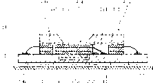
加速度传感器201包括纵向效应型检测部203和横向效应型检测部204。纵向效应型检测部203包括由薄膜压电体211a和电极211b、211c构成的纵向效应型压电元件211。横向效应型检测部204设有横向效应型压电元件213,使其支撑在底板105上形成的沟状凹部105a的上方附近。检测电路116根据纵向效应型检测部203和横向效应型检测部204两者的输出检测出规定方向上加速度等。因此,能够检测规定方向上的加速度并实现大动态范围和宽频带。

The acceleration sensor 201 includes a longitudinal effect type detection part 203 and a lateral effect type detection part 204 . The longitudinal effect type detection unit 203 includes a longitudinal effect type piezoelectric element 211 composed of a thin film piezoelectric body 211a and electrodes 211b and 211c. The lateral effect type detection unit 204 is provided with a lateral effect type piezoelectric element 213 so as to be supported above and near the groove-like recess 105 a formed on the bottom plate 105 . The detection circuit 116 detects acceleration in a predetermined direction and the like based on the outputs of both the longitudinal effect type detection unit 203 and the lateral effect type detection unit 204 . Therefore, it is possible to detect acceleration in a prescribed direction and realize a large dynamic range and a wide frequency band.
Description
本发明涉及使用压电体检测加速度、冲击、振动等的压电型加速度传感器、加速度检测方法和压电型加速度传感器的制造方法。The present invention relates to a piezoelectric acceleration sensor that detects acceleration, shock, vibration, etc. using a piezoelectric body, an acceleration detection method, and a manufacturing method of the piezoelectric acceleration sensor.
近年来,电介质、特别是强电介质被研究用来作为利用了其热电特性的热电型红外线检测器、利用了其极化反转特性的非易失性存储器和利用了其高介电常数特性的电容性元件等,同时,还被研究用来作为利用了其压电特性的加速度传感器(压电型加速度传感器)和压力传感器、利用了其逆压电效应的促动器等压电元件的关键原材料。In recent years, dielectrics, especially ferroelectrics, have been studied as pyroelectric infrared detectors utilizing their pyroelectric properties, nonvolatile memories utilizing their polarization inversion properties, and nonvolatile memories utilizing their high dielectric constant properties. At the same time, capacitive elements, etc., are also studied as the key to piezoelectric elements such as acceleration sensors (piezoelectric acceleration sensors) and pressure sensors that utilize their piezoelectric properties, and actuators that utilize their inverse piezoelectric effects. raw materials.
用在上述加速度传感器和压力传感器等中的压电元件是利用压电体因受力而产生电荷的‘压电效应’去检测力学量(加速度、压力等)的元件,具有能够得到极高检测灵敏度的特征。The piezoelectric element used in the above-mentioned acceleration sensor and pressure sensor, etc. is an element that uses the "piezoelectric effect" that the piezoelectric body generates charges due to force to detect mechanical quantities (acceleration, pressure, etc.), and has the ability to obtain extremely high detection Sensitivity characteristic.
以下,详细说明上述加速度传感器。再有,因加速度、振动、冲击等是同一物理现象,所以,下面只笼统地称之为加速度。Hereinafter, the above-mentioned acceleration sensor will be described in detail. Furthermore, since acceleration, vibration, impact, etc. are the same physical phenomenon, they will be referred to as acceleration in general below.
加速度传感器根据检测出的作用于压电体的力(加速度)的方向,可分成以下3种类型。Acceleration sensors are classified into the following three types according to the detected direction of the force (acceleration) acting on the piezoelectric body.
(1)纵向效应型:检测出与电轴平行方向上的加速度(1) Longitudinal effect type: the acceleration in the direction parallel to the electric axis is detected
(2)剪切效应型:检测出与电轴平行平面内的和电轴方向不一致方向上的加速度(2) Shear effect type: Detect the acceleration in the direction inconsistent with the direction of the electric axis in a plane parallel to the electric axis
(3)横向效应型:检测出与电轴垂直方向上的加速度(3) Lateral effect type: the acceleration in the direction perpendicular to the electric axis is detected
上述纵向效应型加速度传感器的结构是在压电体的前端设置摆锤,当因摆锤的惯性而使压电体伸缩时,在压电体上产生电荷,它是利用这样的原理进行工作的。该加速度传感器因其机械强度大故能够检测出大的加速度。此外,一般,因其机械共振频率高故能够检测出频率高的振动或急剧变化的加速度。The structure of the above-mentioned longitudinal effect type acceleration sensor is to install a pendulum at the front end of the piezoelectric body. When the piezoelectric body expands and contracts due to the inertia of the pendulum, charges are generated on the piezoelectric body. It works on this principle . This acceleration sensor can detect a large acceleration due to its high mechanical strength. In addition, in general, since the mechanical resonance frequency is high, it is possible to detect high-frequency vibrations or rapidly changing accelerations.
此外,剪切效应型加速度传感器具有与上述纵向效应型相同的结构,当因摆锤的惯性而对压电体作用剪切力时,在压电体上产生电荷,它是利用这样的原理进行工作的。该加速度传感器与纵向效应型一样,能够检测出大的加速度,同时,能够检测出频率高的振动或急剧变化的加速度。In addition, the shear effect type acceleration sensor has the same structure as the above-mentioned longitudinal effect type. When a shear force acts on the piezoelectric body due to the inertia of the pendulum, electric charges are generated on the piezoelectric body. It is based on the principle of work. This acceleration sensor can detect a large acceleration like the longitudinal effect type, and at the same time, it can detect a high-frequency vibration or a sharply changing acceleration.
另一方面,横向效应型加速度传感器的结构是将压电体粘接在具有悬臂梁或两端固定梁结构的弹性板上,因其灵敏度高故能够检测出微小的加速度。此外,一般,因容易实现低的机械共振频率,故容易检测出频率低的振动和缓慢变化的加速度。On the other hand, the lateral effect type acceleration sensor has a structure in which a piezoelectric body is bonded to an elastic plate with a cantilever beam or a beam structure fixed at both ends, and can detect small accelerations due to its high sensitivity. In addition, generally, since it is easy to realize a low mechanical resonance frequency, it is easy to detect low-frequency vibration and slowly changing acceleration.
但是,上述纵向效应型加速度传感器不仅能检测出与电轴平行方向上的加速度,而且,根据与剪切效应型相同的原理,还检测出与电轴平行平面内的和电轴方向不一致方向上的摆锤的加速度。所以,要从输出电压确定是哪个方向上的加速度的作用就很困难,存在不能只准确地检测与电轴平行方向上的加速度的问题。此外,与能够检测出大的加速度相反,难以检测出微小的加速度。However, the above-mentioned longitudinal effect type acceleration sensor can not only detect the acceleration in the direction parallel to the electric axis, but also, according to the same principle as the shear effect type, also detect the acceleration in the direction inconsistent with the electric axis in the plane parallel to the electric axis. The acceleration of the pendulum. Therefore, it is difficult to determine in which direction the acceleration acts from the output voltage, and there is a problem that only the acceleration in the direction parallel to the electric axis cannot be accurately detected. In addition, it is difficult to detect small accelerations, whereas large accelerations can be detected.
另一方面,横向效应型加速度传感器,一般,因其机械共振频率较低故存在难以检测出频率高的振动或急剧变化的加速度的问题。此外,因为压电体粘接在弹性板上,伴随弹性板的挠曲压电体产生变形,由此,间接地检测出加速度,所以,当在制造过程中因弹性板和压电体粘接不充分而出现粘接状态不一致时,往往会增加传感器灵敏度的离散。On the other hand, lateral effect type acceleration sensors generally have a problem in that it is difficult to detect high-frequency vibrations or rapidly changing accelerations because of their low mechanical resonance frequencies. In addition, since the piezoelectric body is bonded to the elastic plate, the piezoelectric body deforms with the deflection of the elastic plate, thereby indirectly detecting the acceleration. Therefore, when the elastic plate and the piezoelectric body are bonded during the manufacturing process, Insufficient bonding state inconsistency tends to increase the dispersion of sensor sensitivity.
鉴于上述问题,本发明的目的在于,提供一种压电型加速度传感器,能够可靠地检测出规定方向上的加速度。此外,能够检测出大的加速度和微小的加速度(大动态范围),同时,还能够检测出高频振动和低频振动或变化剧烈和变化缓慢的加速度(宽频带)。进而,能够降低检测灵敏度的离散,还能够实现轻便小型化和降低制造成本。In view of the above problems, an object of the present invention is to provide a piezoelectric acceleration sensor capable of reliably detecting acceleration in a predetermined direction. In addition, large and small accelerations can be detected (large dynamic range), and at the same time, high-frequency vibrations and low-frequency vibrations or sharply changing and slow-changing accelerations can be detected (broadband). Furthermore, variation in detection sensitivity can be reduced, and reduction in weight and size and manufacturing cost can also be achieved.
此外,本发明的目的在于提供一种使用上述那样的压电型加速度传感器的加速度检测方法。Another object of the present invention is to provide an acceleration detection method using the piezoelectric acceleration sensor as described above.
进而,本发明的目的在于提供一种上述那样的压电型加速度传感器的制造方法。Furthermore, an object of the present invention is to provide a method of manufacturing the piezoelectric acceleration sensor as described above.
这里,首先就达到上述目的的本发明的概要进行说明。本发明的基本原理是,使用具有多个压电元件的压电型加速度传感器,在这些多个传感器的输出的基础上进行信号的合成和运算等,由此,检测出规定方向上的加速度,并得以实现大动态范围和宽频带。具体地说,例如在加速度分量的检测方向上具备具有各向异性的多个压电元件,上述多个压电元件通过分别在相互不同的方向上进行配置能够可靠地检测出规定方向上的加速度。即,假定各方向上的加速度分量是未知数,若具备与该未知数相同个数的压电元件,理论上可以根据这些压电元件的输出求出各加速度分量。此外,通过具备多个加速度检测频率特性互不相同的压电元件并将上述多个压电元件的输出合成,可以以由上述各压电元件的频率特性合成的频率特性来进行加速度的检测。此外,通过具备多个加速度检测灵敏度互不相同的压电元件并将上述多个压电元件的输出合成,可以以由上述各压电元件的检测灵敏度合成的检测灵敏度来进行加速度的检测。Here, first, the outline of the present invention for achieving the above objects will be described. The basic principle of the present invention is to use a piezoelectric acceleration sensor having a plurality of piezoelectric elements, perform signal synthesis and calculation on the basis of the outputs of these multiple sensors, thereby detecting acceleration in a predetermined direction, And to achieve a large dynamic range and wide bandwidth. Specifically, for example, a plurality of piezoelectric elements having anisotropy are provided in the detection direction of the acceleration component, and by arranging the plurality of piezoelectric elements in mutually different directions, the acceleration in a predetermined direction can be reliably detected. . That is, assuming that the acceleration components in each direction are unknowns, if there are the same number of piezoelectric elements as the unknowns, each acceleration component can theoretically be obtained from the outputs of these piezoelectric elements. Also, by providing a plurality of piezoelectric elements having different acceleration detection frequency characteristics and combining the outputs of the plurality of piezoelectric elements, acceleration can be detected with a frequency characteristic synthesized from the frequency characteristics of the piezoelectric elements. Also, by providing a plurality of piezoelectric elements having different acceleration detection sensitivities and combining the outputs of the plurality of piezoelectric elements, acceleration can be detected at a detection sensitivity synthesized from the detection sensitivities of the piezoelectric elements.
下面,进行具体说明。Next, a specific description will be given.
本发明的特征在于,包括:具有第1压电体并与上述第1压电体的伸缩和剪切变形对应输出电压的纵向效应型压电元件;具有第2压电体并与上述第2压电体的挠曲变形对应输出电压的横向效应型压电元件;固定上述纵向效应型压电元件和上述横向效应型压电元件的传感器底板。The present invention is characterized in that it includes: a longitudinal effect type piezoelectric element having a first piezoelectric body and outputting a voltage corresponding to the stretching and shearing deformation of the first piezoelectric body; The bending deformation of the piezoelectric body corresponds to the transverse effect piezoelectric element of the output voltage; the sensor base plate for fixing the longitudinal effect piezoelectric element and the transverse effect piezoelectric element.
因此,在上述横向效应型压电元件中,由于只与产生挠曲变形方向上的加速度分量对应产生横向效应输出电压,所以能够检测出上述方向上的加速度分量。另一方面,在上述纵向效应型压电元件中,与产生伸缩变形方向上的加速度分量对应产生纵向效应输出电压,同时,与产生剪切变形方向上的加速度分量对应产生剪切效应输出电压。因此,通过取上述纵向效应型压电元件的检测输出信号和上述横向效应型压电元件的检测输出信号的差分,可以检测出产生剪切变形方向上的加速度分量。此外,不取上述那样的的差分而是将两个检测输出信号进行比较,由此判别加速度的方向。例如,当纵向效应型压电元件的输出比与上述横向效应型压电元件的输出对应的规定大小还大时,可以判定在纵向效应型压电元件上加有产生剪切变形方向上加速度。另一方面,当只利用纵向效应型压电元件检测加速度时,则可以判定在上述纵向效应型压电元件上只加有产生剪切变形方向上加速度。Therefore, in the transverse effect type piezoelectric element, since the transverse effect output voltage is generated only corresponding to the acceleration component in the direction in which the deflection occurs, the acceleration component in the direction can be detected. On the other hand, in the above-mentioned longitudinal effect piezoelectric element, the longitudinal effect output voltage is generated corresponding to the acceleration component in the direction in which stretching deformation occurs, and the shear effect output voltage is generated corresponding to the acceleration component in the direction in which shear deformation occurs. Therefore, by taking the difference between the detection output signal of the longitudinal effect piezoelectric element and the detection output signal of the transverse effect piezoelectric element, the acceleration component in the direction in which the shear deformation occurs can be detected. In addition, the direction of the acceleration is determined by comparing the two detection output signals without taking the above-mentioned difference. For example, when the output of the longitudinal effect piezoelectric element is larger than the predetermined value corresponding to the output of the transverse effect piezoelectric element, it can be determined that the longitudinal effect piezoelectric element is accelerated in the direction of shear deformation. On the other hand, when only the longitudinal effect piezoelectric element is used to detect the acceleration, it can be determined that only the acceleration in the direction of generating shear deformation is added to the longitudinal effect piezoelectric element.
此外,上述那样的纵向效应型压电元件和横向效应型压电元件,因其频率特性和检测灵敏度不同,通过将两者的检测输出信号合成,可以以由两者的频率特性合成的频率特性来进行加速度的检测,可以实现传感器的宽频带,另一方面,通过有选择地切换两者的检测输出信号,则可以以由两者的检测灵敏度合成的检测灵敏度来进行加速度的检测,可以实现传感器的大动态范围。In addition, since the above-mentioned longitudinal effect type piezoelectric element and transverse effect type piezoelectric element have different frequency characteristics and detection sensitivities, by combining the detection output signals of the two, the frequency characteristic obtained by combining the frequency characteristics of the two can be obtained. The detection of acceleration can be carried out, and the wide frequency band of the sensor can be realized. On the other hand, by selectively switching the detection output signals of the two, the detection of acceleration can be carried out with the detection sensitivity synthesized by the detection sensitivity of the two, which can realize Large dynamic range of the sensor.
作为构成上述那样的纵向效应型压电元件和横向效应型压电元件的压电体,可以使用在成膜底板上成膜的压电体薄膜。若使用这样的压电体薄膜,利用蚀刻图形等的微细加工技术,能够容易形成微小、而且是高精度的压电元件,此外,由于可以不需要部件粘接工序等,所以,能够容易实现传感器的轻便小型化和降低制造成本,通过将压电元件做成各种各样的形状和大小去设定各种频率特性和检测灵敏度,容易实现这些压电元件的集成,降低检测灵敏度的离散并提高可靠性。As the piezoelectric body constituting the longitudinal effect type piezoelectric element and the lateral effect type piezoelectric element described above, a piezoelectric thin film formed on a film formation substrate can be used. If such a piezoelectric thin film is used, microfabrication techniques such as etching patterns can be used to easily form a small and high-precision piezoelectric element. In addition, since the component bonding process can be eliminated, the sensor can be easily realized. Portable and miniaturized and reduced manufacturing costs, by making piezoelectric elements into various shapes and sizes to set various frequency characteristics and detection sensitivities, it is easy to realize the integration of these piezoelectric elements, reduce the dispersion of detection sensitivity and Improve reliability.
此外,当使用在成膜底板上成膜的压电体薄膜作为上述那样的压电体来形成横向效应型压电元件时,通过在成膜底板上利用蚀刻等将与横向效应型压电元件相接的部分中的一部分去掉,可以确保压电元件得以挠曲的空间,能够形成微小的可检测出横向效应加速度的加速度传感器。更具体一点说,例如通过利用蚀刻从成膜底板中上的横向效应型压电元件的周围将上述成膜底板的上述一部分除去,可以形成悬臂粱结构,两端固定粱结构和双悬臂粱结构等的横向效应型压电元件。此外,通过从与成膜底板的形成横向效应型压电元件一侧相反的一侧,利用蚀刻将成膜底板的上述一部分去掉,进而可以形成周围部分固定的膜片结构的横向效应型压电元件。In addition, when forming a lateral effect type piezoelectric element using a piezoelectric thin film formed on a film formation substrate as the above-mentioned piezoelectric body, the lateral effect type piezoelectric element is separated from the lateral effect type piezoelectric element by etching or the like on the film formation substrate. Removing some of the connected parts can ensure a space for the piezoelectric element to bend, and can form a tiny acceleration sensor that can detect lateral effect acceleration. More specifically, for example, by removing the above-mentioned part of the above-mentioned film-forming base plate from the periphery of the lateral-effect type piezoelectric element on the film-forming base plate by etching, a cantilever beam structure, a fixed beam structure at both ends, and a double cantilever beam structure can be formed. and other transverse effect piezoelectric elements. In addition, by removing the above-mentioned part of the film-forming base plate by etching from the side opposite to the side of the film-forming base plate where the lateral-effect piezoelectric element is formed, a lateral-effect piezoelectric element with a fixed diaphragm structure can be formed. element.
【图1】实施形态1的压电型加速度传感器的纵剖面图[FIG. 1] A longitudinal sectional view of a piezoelectric acceleration sensor according to
【图2】图1的A-A向剖面图[Figure 2] A-A sectional view of Figure 1
【图3】实施形态1的压电型加速度传感器的检测电路的电路图[FIG. 3] A circuit diagram of the detection circuit of the piezoelectric acceleration sensor according to
【图4】表示实施形态1的压电型加速度传感器的制造工序的说明图[FIG. 4] An explanatory view showing the manufacturing process of the piezoelectric acceleration sensor according to
【图5】表示实施形态1的压电型加速度传感器的制造工序的说明图[FIG. 5] An explanatory view showing the manufacturing process of the piezoelectric acceleration sensor according to
【图6】实施形态2的压电型加速度传感器的纵剖面图[ Fig. 6 ] A longitudinal sectional view of a piezoelectric acceleration sensor according to Embodiment 2
【图7】图6的B-B向剖面图[Fig. 7] B-B sectional view of Fig. 6
【图8】表示实施形态2的压电型加速度传感器的制造工序的说明图[FIG. 8] An explanatory view showing the manufacturing process of the piezoelectric acceleration sensor according to Embodiment 2.
【图9】表示实施形态2的压电型加速度传感器的制造工序的说明图[FIG. 9] An explanatory view showing the manufacturing process of the piezoelectric acceleration sensor according to Embodiment 2.
【图10】表示实施形态2的压电型加速度传感器的制造工序的说明图[ Fig. 10 ] Explanatory diagram showing the manufacturing process of the piezoelectric acceleration sensor according to the second embodiment
【图11】表示实施形态2的压电型加速度传感器的制造工序的说明图[ Fig. 11 ] Explanatory diagram showing the manufacturing process of the piezoelectric acceleration sensor according to the second embodiment
【图12】实施形态3的压电型加速度传感器的纵剖面图[ Fig. 12 ] A longitudinal sectional view of a piezoelectric acceleration sensor according to Embodiment 3
【图13】图12的C-C向剖面图【Figure 13】C-C sectional view of Figure 12
【图14】实施形态4的压电型加速度传感器的纵剖面图[ Fig. 14 ] A longitudinal sectional view of a piezoelectric acceleration sensor according to Embodiment 4
【图15】图14的D-D向剖面图[Fig. 15] D-D sectional view of Fig. 14
【图16】表示实施形态4的压电型加速度传感器的制造工序的说明图[FIG. 16] An explanatory view showing the manufacturing process of the piezoelectric acceleration sensor according to Embodiment 4.
【图17】表示实施形态4的压电型加速度传感器的制造工序的说明图[ Fig. 17 ] Explanatory diagram showing the manufacturing process of the piezoelectric acceleration sensor according to Embodiment 4
【图18】表示实施形态4的压电型加速度传感器的制造工序的说明图[FIG. 18] An explanatory view showing the manufacturing process of the piezoelectric acceleration sensor according to Embodiment 4.
【图19】表示实施形态4的压电型加速度传感器的制造工序的说明图[ Fig. 19 ] Explanatory diagram showing the manufacturing process of the piezoelectric acceleration sensor according to Embodiment 4
下面,参照附图,就本发明的压电型加速度传感器及其制造方法的实施形态进行说明。Next, embodiments of the piezoelectric acceleration sensor and its manufacturing method according to the present invention will be described with reference to the drawings.
(实施形态1)(Embodiment 1)
加速度传感器101的构成如图1和图2所示,在由底102a和盖102b形成的盒子102的内部设置具有纵向效应型检测部103和横向效应型检测部104的底板(传感器底板)105。底板105由金属杆106支持。The structure of the acceleration sensor 101 is as shown in FIGS. 1 and 2. A bottom plate (sensor bottom plate) 105 having a longitudinal effect
上述纵向效应型检测部103是将不锈钢摆锤112粘接在纵向效应型压电元件111的上部形成。上述纵向效应型压电元件111是在作为PZT(钛酸锆酸铅)等烧结体的压电体111a的两面形成由金形成的电极111b、111c并进行极化处理形成的。The longitudinal effect
此外,横向效应型检测部104在底板105上形成的沟状凹部105a的上方附近设置横向效应型压电元件113,形成悬臂支持结构。上述横向效应型压电元件113分别在其两面形成由金形成的电极113b、113b’、113c、113c’,具有贴合了使极化方向相反的压电体113a、113a’的串联双压电晶片的结构。In addition, the lateral effect
上述纵向效应型压电元件111的电极111b、111c和横向效应型压电元件113的电极113b、113c分别经接合线114与底板105上形成的中继端子115连接。中继端子115进而与设在底板105的里侧的包含有场效应晶体管和电阻等的检测电路116连接。The electrodes 111b and 111c of the longitudinal effect
检测电路116例如如图3所示,构成为包括:阻抗变换电路(缓冲放大器)151、152;用来对纵向效应型检测部103的检测灵敏度和横向效应型检测部104的检测灵敏度进行调整的乘法电路153;对纵向效应型检测部103和横向效应型检测部104的检测信号进行加减运算的加法电路154和减法电路155;和选择纵向效应型检测部103或横向效应型检测部104的检测信号的选择电路156。
在上述那样构成的加速度传感器101中,能够正确地判别图1和图2所示的Z轴方向的加速度成分以及X轴和Y轴方向的加速度分量并检测出来。即,在横向效应型压电元件113中,因为只按照Z轴方向的加速度分量产生横向效应输出电压,所以由此可检测出Z轴方向的加速度分量。另一方面,在纵向效应型压电元件111中,在按照Z轴方向的加速度分量产生纵向效应输出电压的同时,还按照X轴方向和Y轴方向的加速度分量产生剪切效应输出电压。因此,利用减法电路155从纵向效应型压电元件111的检测信号中减去横向效应型压电元件113的检测信号,由此可检测出XY平面内方向的加速度分量。In the acceleration sensor 101 configured as described above, the acceleration components in the Z-axis direction and the acceleration components in the X-axis and Y-axis directions shown in FIGS. 1 and 2 can be accurately discriminated and detected. That is, in the transverse effect type
再有,也可以或者不使用与加速度分量的大小对应的检测信号、或者在使用这种检测信号的同时,将纵向效应型压电元件111的检测信号与横向效应型压电元件113的检测信号进行比较,输出表示究竟是哪个方向的加速度起了作用的信号。即,当用横向效应型压电元件113检测出了加速度时,可以判定至少Z轴方向的加速度起了作用。进而,当用纵向效应型压电元件111检测出的加速度比用横向效应型压电元件113检测出的加速度还大时,可以判定Z轴方向的加速度和XY平面内方向的加速度都起作用,此外,若相等时,可以判定只有Z轴方向的加速度起了作用。另一方面,当只有用纵向效应型压电元件111检测出了加速度时,可以判定只有XY平面内方向的加速度起了作用。(当只需要进行该判定时,不必对纵向效应型压电元件111和横向效应型压电元件113的检测灵敏度进行调整,所以也可以不设乘法电路。)Furthermore, it is also possible not to use the detection signal corresponding to the magnitude of the acceleration component, or to combine the detection signal of the longitudinal effect
此外,若按照上述加速度传感器101,对于Z轴方向的加速度,可以以宽频带和大动态范围检测出加速度。即,因为纵向效应型压电元件111的机械共振频率高,而横向效应型压电元件113的机械共振频率低,所以,通过利用加法电路154将两者的检测输出信号合成,就可以检测出从低频振动到高频振动(从变化缓慢的加速度到变化剧烈的加速度)的宽频带的加速度。此外,因为纵向效应型压电元件111能够检测出较大的加速度,而横向效应型压电元件113能够检测出微小的加速度,所以,通过利用选择电路156与加速度的大小对应在两者之中进行切换,可以在大动态范围内检测出加速度。Furthermore, according to the acceleration sensor 101 described above, acceleration in the Z-axis direction can be detected with a wide frequency band and a large dynamic range. That is, since the mechanical resonance frequency of the longitudinal effect
再有,为了检测出上述各方向的加速度成分或谋求大动态范围,纵向效应型压电元件111的共振频率与横向效应型压电元件113的共振频率最好接近,另一方面,为了谋求宽频带,两者的共振频率最好相差很大。因此,各压电元件的共振频率可以在考虑将重点放在提高加速度分量的检测精度、实现宽频带上还是放在实现大动态范围上之后再进行设定。也可以设置多个共振频率互不相同的同一种压电元件,得以同时实现提高加速度分量的检测精度、宽频带和大动态范围。Furthermore, in order to detect the acceleration components in the above-mentioned directions or to achieve a large dynamic range, the resonance frequency of the longitudinal effect
下面,就上述加速度传感器101的制造方法进行说明。Next, a method of manufacturing the above-mentioned acceleration sensor 101 will be described.
(1)首先,在作为PZT(钛酸锆酸铅)等烧结体的压电体111a的两面例如用真空蒸镀法形成金属膜后形成电极111b、111c,进行极化处理,形成纵向效应型压电元件111。利用例如环氧树脂粘接剂在该纵向效应型压电元件111的一侧粘接不锈钢摆锤112,形成纵向效应型检测部103。再有,也可以利用电镀法等使其附着镍等金属去代替粘接摆锤112。这时,能够容易降低因纵向效应型压电元件111和摆锤112的粘接状态的不一致而引起的灵敏度的离散。(1) First, form electrodes 111b and 111c after forming a metal film on both sides of a piezoelectric body 111a that is a sintered body such as PZT (lead zirconate titanate), for example, by vacuum evaporation, and then perform polarization treatment to form a longitudinal effect type piezoelectric body.
(2)其次,如图4所示那样,将分别在其两侧形成了电极113b、113b’、113c、113c’的压电体113a、113a’贴合在一起,使其极化方向互相相反,形成横向效应型压电元件113,作为横向效应型检测部104。(2) Next, as shown in FIG. 4, the piezoelectric bodies 113a, 113a' having electrodes 113b, 113b', 113c, and 113c' formed on both sides thereof are attached together so that the polarization directions are opposite to each other. , forming a lateral effect type
(3)如图5所示,利用环氧树脂粘接剂将上述纵向效应型检测部103和横向效应型检测部104粘接在经金属杆106支撑在底部件102a上的底板105上。更详细地说,纵向效应型检测部103粘接在底板105的平坦部分,另一方面,横向效应型检测部104粘接在其一端,呈悬臂形支撑在底板105的凹部105a的上方附近。(3) As shown in FIG. 5 , the above-mentioned longitudinal effect
(4)利用屏蔽线114将纵向效应型检测部103和横向效应型检测部104的电极111b、111c、113b、113c和设在底板105上的中继端子115连接起来。(4) Connect the electrodes 111b, 111c, 113b, 113c of the longitudinal effect
(5)如上述图1所示那样,例如利用焊接将底102a和盖102b接合起来,并密封纵向效应型检测部103。(5) As shown in FIG. 1 above, the
如上所述,可以得到具有上述那样的检测加速度的指向性、宽频带和大动态范围而且是小型轻便的加速度传感器101。As described above, it is possible to obtain a compact and lightweight acceleration sensor 101 that has the above-mentioned directivity of detected acceleration, a wide frequency band, and a large dynamic range.
再有,在上述例子中,示出了使用双压电晶片结构作为横向效应压电元件113的例子,但并不局限于此,也可以采用使用了单一极化方向的压电体的单压电晶片结构。In addition, in the above example, an example of using a bimorph structure as the lateral effect
此外,示出了将横向效应压电元件113做成悬臂粱结构,但也可以做成两端固定梁结构,或压电元件支撑在中央部分的双悬臂梁结构,进而,还可以做成平板状的压电元件在其周围支撑的薄膜结构。In addition, it is shown that the transverse effect
(实施形态2)(Embodiment 2)
说明作为压电元件使用了在MgO(氧化镁)单结晶底板上结晶生长成的元件的加速度传感器的例子。再有,在下面的实施形态中,对于具有与别的实施形态相同的结构或相同的功能的结构部件,附加相同或对应的符号并适当地省略其说明。An example of an acceleration sensor using an element crystal-grown on a MgO (magnesia) single crystal substrate as a piezoelectric element will be described. In the following embodiments, the same or corresponding reference numerals are attached to components having the same configuration or function as those of other embodiments, and descriptions thereof are appropriately omitted.
加速度传感器201如图6和图7所示,包括一体形成的2个纵向效应型检测部203和1个横向效应型检测部204。这里,纵向效应型检测部203不一定必须设置2个,通过设置多个可以容易提高检测灵敏度。As shown in FIGS. 6 and 7 , the
上述纵向效应型检测部203由成膜底板221和纵向效应型压电元件211构成。成膜底板221由厚度为500μm、结晶方位由(100)的MgO形成。纵向效应型压电元件211的形成是在成膜底板221的两端附近的表面(图6的下面侧)形成由白金薄膜形成的电极211b、由下述(表1)例示的压电体薄膜材料形成的压电体211a、和由白金薄膜形成的电极211c。这里,上述成膜底板221是形成上述那样的纵向效应型压电元件211的各薄膜的底板,同时还起纵向效应型检测部203的摆锤的作用。The above-mentioned longitudinal effect
此外,横向效应型检测部204由横向效应型压电元件213和振动板薄膜222构成。上述横向效应型压电元件213的形成与纵向效应型压电元件211一样,形成由白金薄膜形成的电极213b、由压电体薄膜材料形成的压电体213a、和由白金薄膜形成的电极213c。振动板薄膜222由镍铬(NiCr)薄膜形成,具有与压电体213a相同的厚度。该横向效应型检测部204通过在底板105和成膜底板221上形成凹部105a、221a,成为悬臂支撑结构。In addition, the lateral effect
【表1】【表1】 压电体薄膜的成膜条件
在上述那样构成的加速度传感器201中,与上述实施形态1的加速度传感器101一样,能够检测出各方向的加速度分量,同时,能够以宽频带和大动态范围检测加速度。而且,由于起摆锤作用的成膜底板221和纵向效应型压电元件211的结合以及横向效应型压电元件213和振动板薄膜的结合不是使用粘接而是利用薄膜形成技术进行的,所以,能够降低灵敏度的离散,还可以提高可靠性。此外,由于纵向效应型检测部203和横向效应型检测部204是一体形成的,所以,减少了部件个数,可以降低制造成本。
下面,说明上述加速度传感器201的制造方法。Next, a method of manufacturing the
(1)如图8所示,在由厚度为500μm、结晶方位为(100)的MgO形成的成膜底板221的表面,依次成膜电极薄膜231、压电体薄膜232和电极薄膜233。详细的步骤是,(1) As shown in FIG. 8 , an electrode
(1-1)首先,在由厚度为500μm、结晶方位为(100)的MgO形成的成膜底板221上,利用高频磁控管溅射法,在以下的溅射成膜条件下使由白金形成的厚度为0.15μm的电极薄膜231成膜。(1-1) First, on the film-forming
(a)底板温度: 500~700℃(a) Bottom plate temperature: 500~700℃
(b)溅射气体: 氩(50~98%)和氧(50~2%)的混合气体(b) Sputtering gas: a mixed gas of argon (50-98%) and oxygen (50-2%)
(c)气压: 0.1~3pa(c) Air pressure: 0.1~3pa
(d)接入高频功率密度:1~5W/cm2(13.56MHz)(d) Access high frequency power density: 1~5W/cm 2 (13.56MHz)
(e)成膜时间: 1小时(e) Film forming time: 1 hour
(1-2)根据前面(表1)示出的材料和成膜条件成膜压电体薄膜232。通过在这样的条件下成膜,使压电体薄膜232在整个区域具有正方晶格的结晶结构,形成c轴取向的单结晶膜,极化轴优先取向垂直于成膜底板221的表面的方向。(1-2) The piezoelectric
(1-3)与上述(1-1)一样,使由白金形成的厚度为0.15μm的电极薄膜233成膜。(1-3) As in (1-1) above, an electrode
(2)如图9所示,利用蚀刻使电极薄膜233、压电体薄膜232和电极薄膜231形成图形,形成纵向效应型压电元件211和横向效应型压电元件213的电极211c、213c、压电体211a、213a、和电极211b、213b。详细步骤如下,(2) As shown in Fig. 9, utilize etching to make electrode
(2-1)首先,在电极薄膜233上形成规定的掩膜图形,在下述条件下进行溅射蚀刻,形成电极211c、213c。(2-1) First, a predetermined mask pattern is formed on the
(a)真空度: 0.01~1.0乇(a) Vacuum degree: 0.01~1.0 Torr
(b)氢气流量: 1~20sccm(b) Hydrogen flow rate: 1~20sccm
(c)等离子体功率: 100~300W(c) Plasma power: 100~300W
(d)蚀刻时间: 15分(d) Etching time: 15 minutes
(2-20)其次,根据下述(表2)例示的处理条件蚀刻压电体薄膜232,形成压电体211a、213a。(2-20) Next, the piezoelectric
(2-3)进而,与上述(2-1)一样在电极薄膜231上蚀刻图形,形成电极211b、213b。(2-3) Furthermore, in the same manner as in (2-1) above, a pattern is etched on the
【表2】【表2】 压电体薄膜的图形蚀刻方法
(3)在电极213c上形成厚度与压电体薄膜232相同的振动板薄膜222。更详细一点说,例如,利用高频磁控管溅射法,在下述条件下形成镍铬(NiCr)薄膜。(3) The diaphragm
(a)底板温度: 25~300℃(a) Bottom plate temperature: 25~300℃
(b)溅射气体: 氩气(b) Sputtering gas: Argon
(c)气压: 0.1~2.0pa(c) Air pressure: 0.1~2.0pa
(d)接入高频功率密度:1~5W/cm2(13.56MHz)(d) Access high frequency power density: 1~5W/cm 2 (13.56MHz)
再有,作为振动板薄膜222,除了上述NiCr之外,白金(Pt)、铬(Cr)、铝(Al)等扬氏弹性模量高的金属材料较合适,但也可以使用二氧化硅(SiO2)、树脂膜或光致抗蚀膜等绝缘材料。此外,作为成膜方法,不限于利用真空装置的物理方法,象电镀那样的化学方法也能适用。此外,通过上述那样形成振动板薄膜222,能够容易降低横向效应型压电元件213的扭曲等影响,容易将其设定到所要的固有振动频率和强度上,但是,在横向效应型压电元件213单体具有充分的刚度和强度或使用两端固定梁结构等情况下,不一定必须要形成振动板薄膜222,进而,也可以使电极213b、213c具有振动板薄膜222的功能。In addition, as the vibrating
(4)如图10所示,当从上述电极薄膜231形成电极211b和213b时在电极211b和213b之间形成的狭缝状的蚀刻腔231a,利用使用了加热到80℃的磷酸氢溶液的化学蚀刻方法,经过该蚀刻腔231a、在成膜底板221上将横向效应型压电元件213的一端除外的横向效应型压电元件213的下方部分除去,形成凹部221a。这里,为了使成膜底板221上的上述横向效应型压电元件213一端的部分不被蚀刻,将该部分的蚀刻腔231a掩蔽起来即可。(4) As shown in FIG. 10, when the
(5)如图11所示,将在成膜底板221上形成的纵向效应型压电元件211和横向效应型压电元件213粘接到底板105上并固定下来。这时,横向效应型压电元件213大致位于底板105的凹部105A和成膜底板221的凹部221a之间,其一端的部分夹在底板105和成膜底板221之间呈悬臂支持状态。再有,还可以这样,使振动板薄膜222形成为具有与横向效应型压电元件213相同的长度,使振动板薄膜222也呈悬臂支持状态,如此等等。此外,也可以不象上述那样使横向效应型压电元件213一端的部分夹在底板105和成膜底板221之间,只要将其任何一方牢固地固定即可。(5) As shown in FIG. 11 , the longitudinal effect type
(6)利用屏蔽线114将电极211b、211c、213b、213c与设在底板105上的中继端子115连接。(6) The
(7)如上述图6所示,例如利用焊接将底部件102a和盖102b接合起来,并密封纵向效应型检测部203等。(7) As shown in FIG. 6 above, the
如上所述那样,能够容易制造出上述那样的灵敏度离散小、可靠性高、制造成本低的加速度传感器。而且,由于使用蚀刻图形形成纵向效应型压电元件211和横向效应型压电元件213,所以,能够形成微小的纵向效应型压电元件211和横向效应型压电元件213并制造出小型加速度传感器,还容易制造出将多个压电元件按一维或二维配置并集成化的加速度传感器。进而,由于能够容易形成各种各样形状和大小的压电元件,所以,能够容易设定各种不同的机械共振频率和灵敏度(具体地说,对纵向效应型压电元件设定各种不同的横截面积和厚度,对横向效应型压电元件设定各种不同的长度、宽度和厚度),此外,将它们组合起来能够容易实现更宽的频带和更大的动态范围。As described above, it is possible to easily manufacture an acceleration sensor having a small sensitivity variation, high reliability, and low manufacturing cost as described above. Moreover, since the longitudinal effect type
再有,在上述例子中,示出了使用单压电晶片结构作为横向效应压电元件213的例子,但也可以和上述实施形态1一样,采用使极化方向互相相反的压电体贴合在一起的双压电晶片结构。In addition, in the above-mentioned example, an example using a unimorph structure as the lateral effect
此外,与在实施形态1中已说明过的一样,也可以使横向效应压电元件213做成两端固定粱结构、双悬臂梁结构或薄膜结构。In addition, as described in
此外,上面举例示出了将在成膜底板221上形成的纵向效应型压电元件211粘接在底板上并固定下来、使上述成膜底板221起到纵向效应型检测部203的摆锤的作用的结构,但也可以采用别的方法,将摆锤设在纵向效应型压电元件211上,使成膜底板221与底板105固定,或使成膜底板221兼用作为底板105。In addition, the above example shows the method of bonding the longitudinal effect type
(实施形态3)(Embodiment 3)
实施形态3的加速度传感器301如图12和图13所示,与上述实施形态2的加速度传感器相比有以下不同点。As shown in FIGS. 12 and 13, the
(a)使用硅(Si)单结晶底板作为成膜底板321。(a) A silicon (Si) single crystal substrate is used as the
(b)横效应型检测部304上设置两端固定粱结构的横效应型压电元件313。(b) The transverse effect type piezoelectric element 313 with beam structure fixed at both ends is arranged on the transverse effect
(c)使用具有菱面体结晶结构的钛酸锆酸铅(PZT)作为构成纵向效应型检测部303和横向效应型检测部304的纵向效应型压电元件311和横向效应型压电元件313的压电体311a、313a。(c) Using lead zirconate titanate (PZT) having a rhombohedral crystal structure as the longitudinal effect type piezoelectric element 311 and the lateral effect type piezoelectric element 313 constituting the longitudinal effect
其他方面与实施形态2一样。Other aspects are the same as in Embodiment 2.
即,使用结晶方位为(100)的硅单结晶底板(4英寸晶片)作为成膜底板321。此外,形成成膜底板321和底板105的凹部321a、105a使其比横效应型压电元件313短。这里,成膜底板321的凹部321a可以通过使用例如硝酸/氟酸的混合溶液作为蚀刻剂形成。通过形成上述凹部321a、105a,横向效应型压电元件313变成两端固定的两端固定梁结构。这时,与同样长度的悬臂梁相比,机械共振频率提高了。此外,虽然灵敏度降低了,但因强度提高了故容易检测出大的加速度。That is, a silicon single crystal substrate (4-inch wafer) having a crystal orientation of (100) was used as the
此外,构成压电体311a、313a的菱面晶格PZT例如除了目标组成是(0.8PbZr0.56Ti0.44O3+0.2PbO)之外,可以在与上述(表1)同样的条件下成膜。因此,可以形成极化轴优先取向于与成膜底板321的表面垂直的方向的(111)面取向PZT膜。再有,(111)面取向PZT膜能够得到与成膜底板321的结晶面方位无关的效果。The rhombohedral PZT constituting the
上述那样构成的加速度传感器301与上述实施形态1和实施形态2的加速度传感器101、201一样,能够检测出各方向上的加速度分量,同时,能够以宽频带和大动态范围检测出加速度。此外,与实施形态2的加速度传感器201一样,能够得到降低灵敏度的离散、提高可靠性、降低制造成本、实现小型化等效果。
再有,成膜底板321和压电体311a、313a不限于上述材料,也可以使用例如与上述实施形态2所示的材料一样的材料。此外,也可以适用于实施形态1和实施形态2所示的种种变形例。Note that the film-forming
(实施形态4)(Embodiment 4)
实施形态4的加速度传感器401如图14、图15所示,在成膜底板421上形成比横效应型压电元件413的外形还小的孔421a,横效应型压电元件413构成为其周围被支撑的薄膜结构。其余的结构与上述实施形态3相同。当为上述那样的薄膜结构时,横效应型压电元件413容易将其机械共振频率设定得比悬臂梁或两端固定梁高。这时,灵敏度虽然降低了,但强度提高了,所以容易检测出大的加速度。In the
下面说明上述加速度传感器401的制造方法。Next, a method of manufacturing the above-mentioned
(1)如图16所示,在由结晶方位是(100)的单结晶底板(4英寸晶片)形成的成膜底板421的两面,成膜氮化硅膜421,其掩膜材料的膜厚为2000埃。进而,在其一个面上依次成膜电极薄膜431、压电体薄膜432和电极薄膜433。上述氮化硅膜425例如可以在700℃的成膜温度下,使用硅烷(SiH4)和氨(NH3)的混合气体作为反应气体,利用低压化学气相成长法(LPCVD)成膜。另一方面,电极薄膜431、压电体薄膜432和电极薄膜433的材料和成膜方法和上述实施形态2一样。(1) As shown in FIG. 16 , on both sides of a film-forming
(2)与实施形态2一样,如图17所示,利用蚀刻使电极薄膜431、压电体薄膜432和电极薄膜433形成图形,形成构成纵向效应型检测部403和横向效应型检测部404的纵向效应型压电元件411和横向效应型压电元件413的电极411c、413c、压电体411a、413a、和电极411b、413b。还形成振动板薄膜222。(2) As in Embodiment 2, as shown in FIG. 17, the electrode film 431, the piezoelectric film 432, and the electrode film 433 are patterned by etching to form a vertical effect
进而,在一方的氮化硅膜425(图17的下方侧)上,使用未图示的掩蔽图形,将四氟化碳(CF4)作为反应气体,利用反应式活性离子蚀刻法形成蚀刻腔425a。Furthermore, on one silicon nitride film 425 (the lower side in FIG. 17 ), an etching chamber was formed by reactive reactive ion etching using a mask pattern not shown and carbon tetrafluoride (CF 4 ) as a reactive gas. 425a.
(3)如图18所示,利用氢氧化钾(KOH)等碱性溶液的各向异性化学蚀刻方法,经上述蚀刻腔425a,在与成膜底板421中的横向效应型压电元件413对应的位置上形成孔421a。(3) As shown in FIG. 18, using an anisotropic chemical etching method of alkaline solution such as potassium hydroxide (KOH), through the above-mentioned
(4)如图19所示,将在成膜底板421上形成的纵向效应型压电元件411和横向效应型压电元件413粘接到底板105上并固定下来。(4) As shown in FIG. 19 , the longitudinal effect type
(5)利用屏蔽线114将电极411b、411c、413b、413c与设在底板105上的中继端子115连接。(5) The
(6)如上述图14所示,例如利用焊接将底102a和盖102b接合起来,并密封纵向效应型检测部403。(6) As shown in FIG. 14 above, the
上述那样构成的加速度传感器401与上述实施形态1至实施形态3的加速度传感器101~301一样,能够得到可以检测出各方向上的加速度分量等同样的效果。The
再有,本实施形态能够适用于上述实施形态1至实施形态3所示的种种变形例,例如,使用双压电晶片结构作为横向效应型压电元件413,将多个薄膜结构的压电元件按一维或二维形状配置后再集成。In addition, this embodiment can be applied to various modification examples shown in the above-mentioned
此外,在上述实施形态2~4中,示出了将各自规定的横向效应型压电元件的结构(悬臂梁结构、两端固定结构、薄膜结构)等和规定的材料以及成膜方法等进行组合的例子,但并不限于此,可以进行各种各样的组合。即,例如,也可以使用MgO单结晶底板作为成膜底板,形成两端固定粱结构或薄膜结构的横向效应型压电元件等。此外,例如,也可以不象实施形态2、3中那样在成膜底板上的压电元件一侧形成凹部,而是进而进行蚀刻并形成孔,也可以和实施形态4一样使用掩膜材料从成膜底板的里面一侧蚀刻出孔状或带状。In addition, in the above-mentioned Embodiments 2 to 4, it is shown that the respective predetermined structures of the transverse effect type piezoelectric elements (cantilever beam structure, fixed-end structure, thin-film structure) and predetermined materials and film-forming methods are carried out. Examples of combinations are not limited thereto, and various combinations are possible. That is, for example, a MgO single crystal substrate may be used as a film-forming substrate to form a transverse effect type piezoelectric element with a beam structure fixed at both ends or a thin-film structure. In addition, for example, instead of forming a concave portion on the piezoelectric element side of the film-forming substrate as in Embodiments 2 and 3, etching may be performed to form holes, or a mask material may be used as in Embodiment 4 to form a hole. Holes or strips are etched on the inner side of the film-forming bottom plate.
此外,虽然从灵敏度的观点出发最好象实施形态2~4那样使压电体的极化轴方向对底板垂直,但若使压电体的极化轴方向相对底板倾斜,也可以得到上述那样的本发明的效果。In addition, although it is preferable to make the polarization axis direction of the piezoelectric body perpendicular to the base plate as in Embodiments 2 to 4 from the viewpoint of sensitivity, if the polarization axis direction of the piezoelectric body is inclined relative to the base plate, the above-mentioned The effect of the present invention.
此外,实施形态1~4的压电体和电极等以及实施形态2~4的成膜底板等也不限于上述材料和成膜方法等,可以适用于种种材料和成膜方法。In addition, the piezoelectric bodies and electrodes of
此外,在实施形态1~4中,示出了为了形成悬臂粱结构等的横向效应型压电元件而在底板上形成沟状凹部的例子,但并不限于此,例如,也可以在底板上形成孔等,能适当地获得压电体的位置。In addition, in
此外,检测电路并不限于象上述那样设在底板的里面、即加速度传感器的内部,也可以将其全部或一部分设在外部。此外,也可以根据压电元件的静电容量省略阻抗变换电路等。进而,检测电路的构成也不限于图3所示的电路,例如,也可以在对检出信号进行模/数变换之后经过数字运算算出各方向的加速度分量等,实质上能够进行与上述情况等效的检测。此外,检测方法也不限于上述方法,也可以根据上述那样的纵向效应型检测部和横向效应型检测部的特性(共振频率和检测灵敏度)的不同进行各种各样检测。In addition, the detection circuit is not limited to being provided inside the chassis as described above, that is, inside the acceleration sensor, but all or part of it may be provided outside. In addition, an impedance conversion circuit or the like may be omitted depending on the capacitance of the piezoelectric element. Furthermore, the configuration of the detection circuit is not limited to the circuit shown in FIG. 3 . For example, the acceleration components in each direction can be calculated through digital operations after analog/digital conversion of the detection signal. effective detection. In addition, the detection method is not limited to the above-mentioned method, and various detections may be performed according to the difference in characteristics (resonant frequency and detection sensitivity) between the longitudinal effect type detection unit and the lateral effect type detection unit as described above.
此外,为了检测各方向的加速度分量,不限于设置上述那样的纵向效应型压电元件和横向效应型压电元件这样2种压电元件,例如,为了检测3方向的加速度分量,也可以设置3个电轴互相正交的纵向效应型压电元件。即,由于在纵向效应型压电元件中,相对与电轴平行方向上的加速度的灵敏度和相对与电轴垂直方向上的加速度的灵敏度不同,所以,根据上述那样配置的3个压电元件的输出来进行运算,就可以求出作为未知数的3个方向上的加速度分量。进而,也可以将由纵向效应型压电元件和横向效应型压电元件构成的压电元件组同样地配置成3个方向,这样,能够以更高的精度检测出各方向的加速度分量,同时,能够实现宽频带和大动态范围。In addition, in order to detect acceleration components in each direction, it is not limited to provide two types of piezoelectric elements such as the longitudinal effect piezoelectric element and the transverse effect piezoelectric element as described above. For example, in order to detect acceleration components in three directions, three piezoelectric elements may be provided. A longitudinal effect type piezoelectric element whose electric axes are perpendicular to each other. That is, since the longitudinal effect type piezoelectric element has different sensitivity to acceleration in a direction parallel to the electrical axis and sensitivity to acceleration in a direction perpendicular to the electrical axis, the three piezoelectric elements arranged as described above The output is used for calculation, and the acceleration components in the three directions as unknowns can be obtained. Furthermore, the piezoelectric element group composed of the longitudinal effect piezoelectric element and the transverse effect piezoelectric element can also be arranged in three directions in the same way, so that the acceleration components in each direction can be detected with higher accuracy, and at the same time, A wide frequency band and a large dynamic range can be realized.
此外,通过将上述那样的多个压电元件设在1个盒子内,能够容易使加速度传感器小型化,但如果将多个加速度传感器分别设在不同的盒子内来使用,根据同样的原理,也可以实现各方向的加速度分量的检测、宽频带和大动态范围。In addition, by arranging a plurality of piezoelectric elements as described above in one case, the acceleration sensor can be easily miniaturized. Detection of acceleration components in various directions, wide frequency band and large dynamic range can be realized.
Claims (30)
Applications Claiming Priority (6)
| Application Number | Priority Date | Filing Date | Title |
|---|---|---|---|
| JP100777/1998 | 1998-04-13 | ||
| JP10077798 | 1998-04-13 | ||
| JP100777/98 | 1998-04-13 | ||
| JP64733/1999 | 1999-03-11 | ||
| JP64733/99 | 1999-03-11 | ||
| JP6473399A JP2000002714A (en) | 1998-04-13 | 1999-03-11 | Piezoelectric acceleration sensor, acceleration detection means and manufacture of piezoelectric acceleration sensor |
Publications (2)
| Publication Number | Publication Date |
|---|---|
| CN1232969A true CN1232969A (en) | 1999-10-27 |
| CN1145801C CN1145801C (en) | 2004-04-14 |
Family
ID=26405843
Family Applications (1)
| Application Number | Title | Priority Date | Filing Date |
|---|---|---|---|
| CNB99106299XA Expired - Fee Related CN1145801C (en) | 1998-04-13 | 1999-04-13 | Piezoelectric acceleration sensor and its producing method and acceleration detecting method |
Country Status (4)
| Country | Link |
|---|---|
| US (1) | US6263734B1 (en) |
| JP (1) | JP2000002714A (en) |
| KR (1) | KR100563868B1 (en) |
| CN (1) | CN1145801C (en) |
Cited By (1)
| Publication number | Priority date | Publication date | Assignee | Title |
|---|---|---|---|---|
| CN107533082A (en) * | 2015-03-12 | 2018-01-02 | 株式会社村田制作所 | Acceleration detecting and its manufacture method |
Families Citing this family (26)
| Publication number | Priority date | Publication date | Assignee | Title |
|---|---|---|---|---|
| US6382026B1 (en) * | 1998-05-19 | 2002-05-07 | Matsushita Electric Industrial Co., Ltd. | Acceleration sensor and acceleration apparatus using acceleration sensor |
| DE10031793C1 (en) * | 2000-07-04 | 2002-02-07 | Peter Apel | Piezoelectric sensor |
| US6629462B2 (en) * | 2000-07-24 | 2003-10-07 | Matsushita Electric Industrial Co., Ltd. | Acceleration sensor, an acceleration detection apparatus, and a positioning device |
| US7275412B2 (en) * | 2001-08-09 | 2007-10-02 | Matsushita Electric Industrial Co., Ltd. | Drop shock measurement system and acceleration sensor element used in the same |
| TW546477B (en) * | 2001-08-09 | 2003-08-11 | Matsushita Electric Ind Co Ltd | Drop impact determination system and acceleration sensing element used in the drop impact determination system |
| JP4904656B2 (en) * | 2001-09-27 | 2012-03-28 | パナソニック株式会社 | Thin film piezoelectric element and method for manufacturing the same |
| TW589752B (en) * | 2003-05-28 | 2004-06-01 | Au Optronics Corp | Semiconductor acceleration sensor |
| US7104134B2 (en) * | 2004-03-05 | 2006-09-12 | Agilent Technologies, Inc. | Piezoelectric cantilever pressure sensor |
| US7280078B2 (en) | 2004-11-20 | 2007-10-09 | Scenterra, Inc. | Sensor for detecting high frequency signals |
| WO2006055960A2 (en) * | 2004-11-20 | 2006-05-26 | Scenterra, Inc. | Device for emission of high frequency signals |
| JP2006214898A (en) * | 2005-02-04 | 2006-08-17 | Seiko Epson Corp | Piezoelectric device and electronic equipment |
| CN100363743C (en) * | 2005-09-12 | 2008-01-23 | 中北大学 | Resonant Tunneling Piezoresistive Microaccelerometer |
| JP2007171059A (en) * | 2005-12-22 | 2007-07-05 | Univ Nagoya | Sensor device |
| CN100429520C (en) * | 2006-08-04 | 2008-10-29 | 重庆大学 | A piezoelectric three-dimensional acceleration sensor |
| JP4432990B2 (en) * | 2007-03-22 | 2010-03-17 | セイコーエプソン株式会社 | Sensor and electronic equipment |
| US8011237B2 (en) * | 2008-02-22 | 2011-09-06 | Hong Kong Applied Science And Technology Research Institute Co., Ltd. | Piezoelectric module for energy harvesting, such as in a tire pressure monitoring system |
| SG189026A1 (en) | 2010-09-22 | 2013-05-31 | Univ Singapore | Vibration detector and method |
| CA2820874A1 (en) * | 2010-12-08 | 2012-06-14 | Microfine Materials Technologies Pte Ltd | High-performance bending accelerometer |
| JP5066271B2 (en) * | 2011-03-04 | 2012-11-07 | Necトーキン株式会社 | Piezoelectric acceleration sensor |
| US8724832B2 (en) * | 2011-08-30 | 2014-05-13 | Qualcomm Mems Technologies, Inc. | Piezoelectric microphone fabricated on glass |
| KR101354757B1 (en) | 2011-11-18 | 2014-01-22 | 삼성전기주식회사 | Inertial Sensor |
| US8991251B1 (en) * | 2011-11-21 | 2015-03-31 | Western Digital (Fremont), Llc | Hybrid capacitive and piezoelectric motion sensing transducer |
| JP6141598B2 (en) * | 2012-01-17 | 2017-06-07 | セイコーエプソン株式会社 | pressure sensor |
| KR101320185B1 (en) * | 2012-09-19 | 2013-10-23 | 삼성전기주식회사 | Vibrating actuator |
| CN108398181B (en) | 2018-02-06 | 2024-06-25 | 麒盛科技股份有限公司 | Integrated physiological signal detection sensor |
| FR3112392B1 (en) * | 2020-07-07 | 2022-07-22 | Autovib | Triaxial industrial accelerometer |
Family Cites Families (13)
| Publication number | Priority date | Publication date | Assignee | Title |
|---|---|---|---|---|
| JPH0665871B2 (en) | 1986-06-28 | 1994-08-24 | 日本電装株式会社 | Fuel injection device for internal combustion engine |
| JP3126212B2 (en) | 1992-03-21 | 2001-01-22 | 日本碍子株式会社 | Piezoelectric / electrostrictive film type element |
| JP2689799B2 (en) | 1991-12-27 | 1997-12-10 | 株式会社村田製作所 | Acceleration sensor |
| DE69423667T2 (en) * | 1993-03-01 | 2000-11-23 | Murata Mfg. Co., Ltd. | Piezoelectric vibrator and acceleration sensor using this |
| JP3308368B2 (en) * | 1993-12-17 | 2002-07-29 | マイクロジェニックス株式会社 | 3-axis piezoelectric acceleration sensor |
| JPH07202283A (en) * | 1993-12-28 | 1995-08-04 | Tdk Corp | Piezoelectric sensor and its manufacture |
| DE4428124B4 (en) * | 1994-08-09 | 2005-08-18 | Robert Bosch Gmbh | accelerometer |
| JPH0949855A (en) * | 1995-08-08 | 1997-02-18 | Tdk Corp | Piezoelectric sensor |
| US5677487A (en) * | 1995-10-13 | 1997-10-14 | A/S Bruel & Kjaer | Method and apparatus for measuring acceleration or mechanical forces |
| JP3277794B2 (en) * | 1996-01-12 | 2002-04-22 | 株式会社村田製作所 | Acceleration sensor |
| JPH09298327A (en) | 1996-05-07 | 1997-11-18 | Sony Corp | Piezoelectric ceramic transformer |
| JP3311633B2 (en) * | 1997-04-04 | 2002-08-05 | 日本碍子株式会社 | Sensor unit |
| US5983722A (en) * | 1997-11-12 | 1999-11-16 | K.K. Holding Ag | Piezobloc accelerometer |
-
1999
- 1999-03-11 JP JP6473399A patent/JP2000002714A/en active Pending
- 1999-04-10 KR KR1019990012652A patent/KR100563868B1/en not_active IP Right Cessation
- 1999-04-13 CN CNB99106299XA patent/CN1145801C/en not_active Expired - Fee Related
- 1999-04-13 US US09/289,936 patent/US6263734B1/en not_active Expired - Fee Related
Cited By (1)
| Publication number | Priority date | Publication date | Assignee | Title |
|---|---|---|---|---|
| CN107533082A (en) * | 2015-03-12 | 2018-01-02 | 株式会社村田制作所 | Acceleration detecting and its manufacture method |
Also Published As
| Publication number | Publication date |
|---|---|
| KR100563868B1 (en) | 2006-03-23 |
| CN1145801C (en) | 2004-04-14 |
| JP2000002714A (en) | 2000-01-07 |
| KR19990083114A (en) | 1999-11-25 |
| US6263734B1 (en) | 2001-07-24 |
Similar Documents
| Publication | Publication Date | Title |
|---|---|---|
| CN1232969A (en) | Piezoelectric acceleration sensor, manufacturing method thereof, and acceleration detection method | |
| KR100931575B1 (en) | Piezoelectric element micro speaker using MEMS and its manufacturing method | |
| CN102124643B (en) | Piezoelectric power generation device | |
| US9662680B2 (en) | Ultrasonic transducer | |
| KR100408609B1 (en) | A piezoelectric type electric acoustic converter | |
| CN102859862B (en) | Vibration power generation device | |
| US9636709B2 (en) | Ultrasonic generation device | |
| CN108140723B (en) | Piezoelectric element, piezoelectric microphone, piezoelectric resonator, and method for manufacturing piezoelectric element | |
| US20130061438A1 (en) | Piezoelectric speaker and method of manufacturing the same | |
| CN1795699A (en) | Sound detection mechanism | |
| US7952248B2 (en) | Piezoelectric generator | |
| US9135906B2 (en) | Ultrasonic generator | |
| JP4758998B2 (en) | Piezoelectric vibrator with multi-action vibrator | |
| WO2011043219A1 (en) | Piezoelectric acceleration sensor | |
| JP2008205888A (en) | Method for manufacturing piezoelectric vibrating piece and piezoelectric vibrating element | |
| KR20180008242A (en) | Bulk Acoustic wave filter device | |
| WO2011136312A1 (en) | Vibration power generation device and method for manufacturing same | |
| JP5233466B2 (en) | Vibrator, oscillator, and method for producing the vibrator | |
| US9252350B2 (en) | Oscillation piece, oscillator, electronic device, electronic apparatus, and mobile object | |
| CN1103137C (en) | Piezoelectric resonator and electronic component device using the same | |
| WO2020085188A1 (en) | Resonance device | |
| JPH10173476A (en) | Tuning fork piezoelectric oscillator | |
| JP6829823B2 (en) | Resonator and resonator | |
| JP2011108680A (en) | Method of manufacturing multilayer substrate, method of manufacturing diaphragm, and method of manufacturing pressure sensor | |
| WO2019188381A1 (en) | Vibration element |
Legal Events
| Date | Code | Title | Description |
|---|---|---|---|
| C06 | Publication | ||
| PB01 | Publication | ||
| C10 | Entry into substantive examination | ||
| SE01 | Entry into force of request for substantive examination | ||
| C14 | Grant of patent or utility model | ||
| GR01 | Patent grant | ||
| C17 | Cessation of patent right | ||
| CF01 | Termination of patent right due to non-payment of annual fee |
Granted publication date: 20040414 Termination date: 20130413 |