CN1223706A - crowd control barrier - Google Patents
crowd control barrier Download PDFInfo
- Publication number
- CN1223706A CN1223706A CN 97196027 CN97196027A CN1223706A CN 1223706 A CN1223706 A CN 1223706A CN 97196027 CN97196027 CN 97196027 CN 97196027 A CN97196027 A CN 97196027A CN 1223706 A CN1223706 A CN 1223706A
- Authority
- CN
- China
- Prior art keywords
- base portion
- barrier assembly
- barrier
- assembly
- elongated
- Prior art date
- Legal status (The legal status is an assumption and is not a legal conclusion. Google has not performed a legal analysis and makes no representation as to the accuracy of the status listed.)
- Pending
Links
- 230000004888 barrier function Effects 0.000 title claims abstract description 105
- XLYOFNOQVPJJNP-UHFFFAOYSA-N water Substances O XLYOFNOQVPJJNP-UHFFFAOYSA-N 0.000 claims abstract description 23
- 239000007788 liquid Substances 0.000 claims abstract description 14
- 230000007246 mechanism Effects 0.000 claims description 23
- 230000008878 coupling Effects 0.000 claims description 12
- 238000010168 coupling process Methods 0.000 claims description 12
- 238000005859 coupling reaction Methods 0.000 claims description 12
- 239000012530 fluid Substances 0.000 claims 1
- 230000009194 climbing Effects 0.000 abstract description 9
- 230000000712 assembly Effects 0.000 description 20
- 238000000429 assembly Methods 0.000 description 20
- 238000000034 method Methods 0.000 description 5
- 230000004048 modification Effects 0.000 description 3
- 238000012986 modification Methods 0.000 description 3
- 238000000465 moulding Methods 0.000 description 3
- 241001503987 Clematis vitalba Species 0.000 description 2
- 230000008901 benefit Effects 0.000 description 2
- 230000000295 complement effect Effects 0.000 description 2
- 230000006378 damage Effects 0.000 description 2
- 239000004698 Polyethylene Substances 0.000 description 1
- 208000027418 Wounds and injury Diseases 0.000 description 1
- 238000010521 absorption reaction Methods 0.000 description 1
- 230000000903 blocking effect Effects 0.000 description 1
- 238000010276 construction Methods 0.000 description 1
- 230000005484 gravity Effects 0.000 description 1
- 238000002347 injection Methods 0.000 description 1
- 239000007924 injection Substances 0.000 description 1
- 208000014674 injury Diseases 0.000 description 1
- 239000000463 material Substances 0.000 description 1
- 229920003023 plastic Polymers 0.000 description 1
- 239000004033 plastic Substances 0.000 description 1
- -1 polyethylene Polymers 0.000 description 1
- 229920000573 polyethylene Polymers 0.000 description 1
- 230000001105 regulatory effect Effects 0.000 description 1
- 230000000284 resting effect Effects 0.000 description 1
- 238000001175 rotational moulding Methods 0.000 description 1
Images


Landscapes
- Refuge Islands, Traffic Blockers, Or Guard Fence (AREA)
Abstract
Description
发明的技术领域technical field of invention
本发明涉及改进的屏障及其组件,它特别但并非唯一涉及人群控制屏障,这种屏障用于界定行人或车辆应当遵守的路线,并用于防止进入特定区域,特别是那些可能适合于警察或其它管理机构人员巡逻的区域。This invention relates to improved barriers and components thereof, particularly but not exclusively to crowd control barriers used to define routes that pedestrians or vehicles should follow and to prevent access to certain areas, especially those that might be suitable for police or other An area patrolled by agency personnel.
利用除坚硬的或永久性的基本上不动的栅栏以外的人群控制方法已越来越需要。街头示威者,体育比赛观众和其他情绪激动的人们可能迅速组成这样的人群,其行进无法由可以调用的警察或其它管理机构人员阻挡,因此将产生人身伤害或财产损坏的结果。There is an increasing need to utilize crowd control methods other than rigid or permanent substantially immobile fencing. Street demonstrators, sports game spectators, and other emotionally charged people can quickly form such a crowd that their progress cannot be stopped by available police or other regulatory agency personnel, thereby resulting in personal injury or property damage.
背景技术Background technique
已知各种轻便的或可以运输的屏障,但通常这些屏障均用于引导车辆交通或保护人员与车辆交通隔开,特别在道路工程正在进行的部位。Various portable or transportable barriers are known, but generally these are used to direct vehicular traffic or to protect persons from vehicular traffic, particularly where roadworks are in progress.
例如,SEROC SA的瑞士专利申请No.676864和No.683540例示一种交通屏障,它有一个混凝土底座和一对置于底座上方的间隔开的导轨,但此种屏障高度低且能够容易地攀登,因此对人群控制无效,Energy Absorption System公司的欧洲专利申请No.589605例示一种交通控制用的空心屏障组件,但该组件对人群控制也无效,因为它能够容易地被攀登,其中提供的脊部允许有效地抓住以便爬上。For example, Swiss Patent Applications No. 676864 and No. 683540 by SEROC SA illustrate a traffic barrier that has a concrete base and a pair of spaced rails placed above the base, but is low in height and can be easily climbed , so ineffective for crowd control, Energy Absorption System's European Patent Application No.589605 exemplifies a hollow barrier assembly for traffic control, but this assembly is also ineffective for crowd control because it can be easily climbed, the ridge provided The underparts allow an efficient grip for climbing.
因而,需要一种新颖形式的屏障,它能在所需位置快速而容易地树立,并将证明对人群控制是有效的,因此本发明的主要目的是满足对此种屏障的需求。Thus, there is a need for a novel form of barrier which can be quickly and easily erected at a desired location and which will prove effective for crowd control and it is therefore the primary object of the present invention to satisfy the need for such a barrier.
本发明的另一目的是方便地提供按一定尺寸制造的屏障组件,它们可以容易地组装以形成一个用于人群控制的屏障,这些组件一旦安置和相互连接,就适用于填充液体,以便增加重量和稳定性,并能在使用后放空,以便恢复运输到其它地点的性能。It is a further object of the present invention to provide conveniently sized barrier assemblies which can be easily assembled to form a crowd control barrier which, once positioned and interconnected, are adapted to be filled with liquid for added weight and stability, and can be vented after use to restore performance for transport to other locations.
本发明的又一目的是提供这样设计的屏障组件,使得能获得最大的紧凑性,没有不适当的大体积,但它在正常状态下不能被骚动者或闲荡者攀登。另一个目的是提供这样的屏障组件,它们一旦连接在相邻的组件上,在正常状态下就不能容易地被骚动者或闲荡者拆开,或被这些人翻倒。再一个目的是提供具有已叙述过的特性的组件,它们允许管理人员通过组件观察人群,和/或能够容易地递送指令,和/或挥舞武器进行可以看见的威吓,但不会由于人群便于攀登而显著减小安全性优点。本发明的其它目的和优点将从后面描述的实施例清楚知道。A further object of the present invention is to provide a barrier assembly of such a design that maximum compactness can be obtained without undue bulkiness, but which cannot be climbed by rioters or loafers in normal conditions. It is a further object to provide barrier assemblies which, once attached to adjacent assemblies, cannot be easily dismantled by rioters or loafers or tipped over by such persons under normal conditions. Yet another object is to provide assemblies of the recited properties that allow supervisors to observe crowds through the assemblies, and/or be able to deliver commands easily, and/or wield weapons for visible intimidation, but without the ease of climbing due to crowds And the safety advantage is significantly reduced. Other objects and advantages of the present invention will be apparent from the embodiments described later.
发明的公开disclosure of invention
鉴于上述和其它目的,本发明的一个方面主要在于这样一种屏障组件,它包括:In view of the foregoing and other objects, an aspect of the present invention consists essentially in a barrier assembly comprising:
一个细长的空心底座部分,适合于安置在地面或等效的表面上,并准备充满液体,最好是水;an elongated hollow base portion suitable for placement on the ground or an equivalent surface and ready to be filled with liquid, preferably water;
一个细长的上部,设置在所述底座部分上方;以及an elongated upper portion disposed above the base portion; and
墙机构,连接所述底座部分和所述上部并形成一个屏障,以防止行人通过其间,所述上部有一个向外和向下弯曲的上表面,从所述墙机构的一侧延伸到所述墙机构的另一侧,以使难于抓住所述上部,由此阻止攀登所述屏障组件。a wall mechanism connecting said base portion and said upper portion and forming a barrier to prevent pedestrians from passing therebetween, said upper portion having an outwardly and downwardly curved upper surface extending from one side of said wall mechanism to said The other side of the wall mechanism to make it difficult to grasp the upper portion, thereby preventing climbing of the barrier assembly.
在另一方面中,本发明主要属于这样一种屏障组件,它包括:In another aspect, the invention generally resides in a barrier assembly comprising:
一个细长的空心底座部分,适合于安置在地面或等效的表面上,并准备充满液体,最好是水;an elongated hollow base portion suitable for placement on the ground or an equivalent surface and ready to be filled with liquid, preferably water;
一个细长的上部,设置在所述底座部分上方;以及an elongated upper portion disposed above the base portion; and
墙机构,连接所述底座部分和所述上部并在其间形成一个屏障,所述上部有一个向外和向下弯曲的上表面,从所述墙机构的一侧延伸到所述墙机构的另一侧,以使难于抓住所述上部,由此阻止攀登所述屏障组件,所述墙机构包括多个间隔开的细长部件或部分,适合于基本上防止行人通过其间。a wall structure connecting and forming a barrier between said base portion and said upper portion, said upper portion having an outwardly and downwardly curved upper surface extending from one side of said wall structure to the other side of said wall structure On one side, to make it difficult to grasp the upper portion, thereby preventing climbing of the barrier assembly, the wall mechanism includes a plurality of spaced apart elongate members or portions adapted to substantially prevent pedestrians from passing therebetween.
在另一方面中,本发明主要属于这样一种屏障组件,它包括:In another aspect, the invention generally resides in a barrier assembly comprising:
一个细长的空心底座部分,适合于安置在地面或等效的表面上,并准备充满液体,最好是水;an elongated hollow base portion suitable for placement on the ground or an equivalent surface and ready to be filled with liquid, preferably water;
一个细长的上部,设置在所述底座部分上方;以及an elongated upper portion disposed above the base portion; and
墙机构,连接所述底座部分和所述上部并形成一个屏障,以防止行人通过其间,所述底座部分和所述上部的侧向尺寸大于所述墙机构,从而阻止攀登所述屏障组件。a wall mechanism connecting said base portion and said upper portion and forming a barrier to prevent pedestrians from passing therebetween, said base portion and said upper portion having a lateral dimension greater than said wall mechanism to prevent climbing said barrier assembly.
在又一方面中,本发明主要属于这样一种屏障组件,它包括:In yet another aspect, the invention generally resides in a barrier assembly comprising:
一个细长的空心底座部分,适合于安置在地面或等效的表面上,并准备充满液体,最好是水;an elongated hollow base portion suitable for placement on the ground or an equivalent surface and ready to be filled with liquid, preferably water;
一个细长的上部,设置在所述底座部分上方;以及an elongated upper portion disposed above the base portion; and
墙机构,连接所述底座部分和所述上部并在其间形成一个屏障,所述底座部分和所述上部的侧向尺寸大于所述墙机构,所述上部有一个向外和向下弯曲的上表面,从所述墙机构的一侧延伸到所述墙机构的另一侧,以使难于抓住所述上部,由此阻止攀登所述屏障组件,所述墙机构包括多个间隔开的细长部件或部分,它们从所述底座部分向上延伸到所述上部,适合于基本上防止行人通过其间。wall means connecting said base portion and said upper portion and forming a barrier therebetween, said base portion and said upper portion having lateral dimensions greater than said wall means, said upper portion having an outwardly and downwardly curved upper a surface extending from one side of the wall mechanism to the other side of the wall mechanism to make it difficult to grasp the upper portion, thereby preventing climbing of the barrier assembly, the wall mechanism comprising a plurality of spaced apart thin Elongate members or portions extending upwardly from said base portion to said upper portion are adapted to substantially prevent the passage of pedestrians therebetween.
最好是,上部基本上是提供上下弯曲表面的圆柱形,使想要攀登的人甚至更难于抓住。同时最好是,底座部分的上表面向外和向下弯曲,使得一个想要攀登的人难以稳定地站立在其上面,并难以有效地握住而爬上该屏障组件。Preferably, the upper portion is substantially cylindrical providing an up and down curved surface, making it even more difficult for a person wishing to climb. Also preferably, the upper surface of the base portion curves outwardly and downwardly, making it difficult for a person wishing to climb to stand stably thereon and effectively grip and climb the barrier assembly.
最好是,所述细长部件或部分的形状能使站在另一侧的观察者看到越过屏障组件的这一侧的区域,由此该观察者可以从另一侧的受保护的位置确定屏障组件的这一侧的人群的规模、骚动状况及其它有关方面。有利的是,所述细长部件的间隔和形状允许人群控制管理机构如警察控制骚动和其它扰乱,而如果需要,该管理机构可以利用水枪或其它装置通过这些开孔或间隔来驱散人群。同时最好是,所述细长部件或部分是空心的,使得它们可以充满液体,以增大组件重量,同时提供一条在所述底座部分和所述上部(两者在最优形式下也都是空心的)之间液体连通的路径,由此整个屏障组件可以从一个注入孔填充液体。Preferably, the shape of the elongated member or portion enables an observer standing on the other side to see the area beyond this side of the barrier assembly, whereby the observer can view the area from a protected position on the other side. Determine crowd size, commotion and other relevant aspects on this side of the barrier assembly. Advantageously, the spacing and shape of the elongate members allows crowd control authorities, such as the police, to control riots and other disturbances, which authorities can, if desired, use water cannons or other devices to disperse crowds through these openings or spaces. Also preferably, said elongated members or portions are hollow so that they can be filled with liquid to increase the weight of the assembly while providing a strip between said base portion and said upper portion (both also in optimal form). are hollow) through which the entire barrier assembly can be filled with liquid from one injection hole.
最好是,该屏障组件包括联接机构,用于将一个组件联接到相邻的组件上,而且最好这样的联接机构适用于防止一个中间组件从相邻的组件上脱开。在一种优选形式中,该联接机构包括一对设置在组件一端上的对准的指向下面的上下销和一对设置在另一端上的互补的对准的上下插座,由此在使用中,一个组件的各销可以插入一个相邻的屏障组件的各相应插座中。可以理解,在本发明的此种形式中,组件必须从一个包括多个屏障组件的屏障的自由端部上联接和脱开,当充满水时每个组件的重量能有效地防止一个中间组件脱开。其次,在本发明的其中该墙机构包括多个从底座部分延伸到上部的间隔开的细长部件的形式中,该联接机构这样设置,使得一个组件的端部细长部件与相邻组件的端部细长部件的间隔基本上等于每个组件的各细长部件的同样距离,由此,通过一个包括多个联接组件的屏障的所有部分的墙机构保持可以看见的性能,而各相邻屏障组件的墙机构相互配合,形成一个基本上均匀地间隔的部件的连接屏障。Preferably, the barrier assemblies include coupling means for coupling one assembly to an adjacent assembly, and preferably such coupling means are adapted to prevent disengagement of an intermediate assembly from an adjacent assembly. In a preferred form, the coupling mechanism comprises a pair of aligned downwardly pointing upper and lower pins disposed on one end of the assembly and a pair of complementary aligned upper and lower sockets disposed on the other end whereby in use, Pins of one assembly are insertable into corresponding receptacles of an adjacent barrier assembly. It will be appreciated that in this form of the invention, assemblies must be coupled and disconnected from the free ends of a barrier comprising a plurality of barrier assemblies, the weight of each assembly being effective to prevent an intermediate assembly from being disengaged when filled with water. open. Secondly, in those forms of the invention in which the wall means comprises a plurality of spaced apart elongate members extending from a base portion to an upper portion, the coupling mechanism is arranged such that the end elongate members of one assembly are connected to the end elongate members of an adjacent assembly. The spacing of the end elongated members is substantially equal to the same distance of the elongated members of each assembly, whereby the visible performance is maintained through the wall mechanism of all parts of a barrier comprising a plurality of coupled assemblies, while adjacent The wall mechanisms of the barrier assembly cooperate to form a connected barrier of substantially evenly spaced components.
最好是,底座部分在其两端处的形状能使相邻的组件在水平面内进行枢轴式转动,以形成屏障拐角。在一优选形式中,两端是弯曲的,能够进行通过约45度角的枢轴式转动,使得相邻的屏障组件能够包围一个135度的最小值,而在一个这样的形式中,底座部分在两端处的上表面基本上为部分球面形,而该上部的两端基本上为半球形,而且它们适合于紧靠一个相邻的屏障组件的相对端部。Preferably, the base portion is shaped at its ends to allow adjacent components to pivot in the horizontal plane to form barrier corners. In a preferred form, the ends are curved to allow pivoting through an angle of about 45 degrees so that adjacent barrier assemblies can enclose a minimum of 135 degrees, and in one such form the base portion The upper surface at both ends is substantially part-spherical and the ends of the upper portion are substantially hemispherical and adapted to abut against opposite ends of an adjacent barrier assembly.
在一个实用的实施例中,一个典型的组件在侧面立视图中可以是基本上方形的,一个合适的高度为2100毫米,以便满意地阻止成人攀登,为了稳定起见长度相同,因此当充满水时其重量将有效地防止被人群中的一些人或几组人用手翻倒。在此种典型实施例中,底座部分为合适的半圆柱形,该半圆柱形围绕的底面或沿横向的直径的尺寸为1200毫米,安置在合适的承载机构如垫上,其弯曲面在最上部,而使包括多个垂直连接的管子的墙机构从底座部分的最上部中央纵轴方向伸出。在该典型实施例中上细长区段可以是直径约600毫米的圆柱形,使其弯曲的下表面的宽度中间连接在各管子上,使两侧凸出。可以看到,在一典型实施例中,屏障组件各部分的尺寸能有效地基本上防止许多人不用机器就能将组件翻倒,也能有效地防止或至少很大程度上阻止攀登。其次,屏障组件的各部分的尺寸、比例和曲率使得一个接一个的人链极难(如果并非不可能)推到该组件。In a practical embodiment, a typical assembly may be substantially square in side elevation, a suitable height of 2100mm to satisfactorily deter adults from climbing, and the same length for stability so that when filled with water Its weight will effectively prevent it from being tipped over by hand by some persons or groups of persons in the crowd. In such an exemplary embodiment, the base portion is a suitable semi-cylindrical shape surrounding a base or transverse diameter measuring 1200 mm, resting on a suitable supporting mechanism such as a pad with its curved surface at the uppermost , such that a wall structure comprising a plurality of vertically connected tubes protrudes from the uppermost central longitudinal axis of the base portion. The upper elongated section in this exemplary embodiment may be cylindrical with a diameter of about 600 mm, with its curved lower surface the width of the middle connecting the tubes, so that the sides are convex. It can be seen that in an exemplary embodiment, the dimensions of the barrier assembly portions are effective to substantially prevent the assembly from being tipped over by many persons without a machine, and to prevent, or at least largely prevent, climbing. Second, the size, proportions and curvature of the parts of the barrier assembly make it extremely difficult, if not impossible, to push a human chain one after the other into the assembly.
在另一方面中,本发明主要属于这样一种屏障组件,它包括:In another aspect, the invention generally resides in a barrier assembly comprising:
一个细长的空心底座部分,适合于安置在地面或等效的表面上,并准备充满液体,最好是水;an elongated hollow base portion suitable for placement on the ground or an equivalent surface and ready to be filled with liquid, preferably water;
以所述底座部分向上延伸的壁机构;以及wall means extending upwardly from said base portion; and
一个安置在所述底座部分上方的上部,该上部按操作关系连接到所述墙机构上,以便相对于墙机构转动。在本发明的此种形式中,最好是,所述上部包括一个辊或多个辊。在一种形式中这些辊安装在所述墙机构的延伸部上并且是圆柱形,其转动轴基本上平行于该细长底座部分的纵轴。但是,在其它形式中,这些辊可以自由安装,用于在墙机构的上端中形成的盘内转动,并可以是圆柱形或球形。同时最好是,组件的其它相应特点如本发明的其它方面所相关地描述的。An upper portion is disposed above said base portion and is operatively connected to said wall mechanism for rotation relative to said wall mechanism. In this form of the invention it is preferred that said upper portion comprises a roller or rollers. In one form the rollers are mounted on extensions of said wall means and are cylindrical with their axes of rotation substantially parallel to the longitudinal axis of the elongate base portion. In other forms, however, these rollers may be freely mounted for rotation within a disc formed in the upper end of the wall mechanism, and may be cylindrical or spherical. Also preferably, other corresponding features of the assembly are as described in relation to other aspects of the invention.
可以理解,屏障组件在其上述方面的任一方面中均可包括其它特点,如顶部和底部处的快速脱开配件,由此当需要时可以引入或放掉水,而从下列描述中将会清楚本发明的另外其它特点。It will be appreciated that the barrier assembly in any of its above aspects may include other features, such as quick release fittings at the top and bottom, whereby water can be introduced or drained as required, and will be apparent from the following description Still other features of the present invention are clear.
附图简述Brief description of the drawings
为了可以更容易地理解和实施本发明,现在参照附图,其中:In order that the present invention may be more easily understood and practiced, reference is now made to the accompanying drawings, in which:
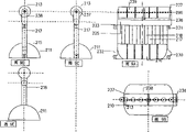
图1表示本发明的屏障组件的一种例示形式的侧视立面图;Figure 1 shows a side elevational view of an illustrative form of the barrier assembly of the present invention;
图2a和3a是图1组件的端视图和剖面端视图,而图2b和3b是另一组件的类似于图2a和3a的端视图和剖面端视图;Figures 2a and 3a are end and cross-sectional end views of the assembly of Figure 1, while Figures 2b and 3b are end and cross-sectional end views of another assembly similar to Figures 2a and 3a;
图4表示图1至3的组件的平面图;Figure 4 represents a plan view of the assembly of Figures 1 to 3;
图5是类似于图3的视图,但表示屏障组件的一种改进形式的剖面图;Figure 5 is a view similar to Figure 3 but showing a cross-sectional view of a modified form of the barrier assembly;
图6a是本发明的屏障组件的另一形式的侧视图;Figure 6a is a side view of another form of the barrier assembly of the present invention;
图6b是图6a的组件的平面图;Figure 6b is a plan view of the assembly of Figure 6a;
图6c是图6a的组件的端视图;Figure 6c is an end view of the assembly of Figure 6a;
图6d是图6a的组件的销的放大截面图;Figure 6d is an enlarged cross-sectional view of a pin of the assembly of Figure 6a;
图7是两个如图6a中所示的组件联接在一起并对准的侧视图;Figure 7 is a side view of two assemblies as shown in Figure 6a coupled together and aligned;
图8是两个如图6a中所示的组件联接在一起但并不对准而围成135度角的平面图;Figure 8 is a plan view of two assemblies as shown in Figure 6a coupled together but not aligned to enclose an angle of 135 degrees;
图9a是本发明的又一种屏障组件的侧视图;Figure 9a is a side view of yet another barrier assembly of the present invention;
图9b是图9a的屏障组件的平面图;Figure 9b is a plan view of the barrier assembly of Figure 9a;
图9c和9d是图9a的屏障组件的两个端视图;Figures 9c and 9d are two end views of the barrier assembly of Figure 9a;
图9e是图9a的屏障组件的剖面图;以及Figure 9e is a cross-sectional view of the barrier assembly of Figure 9a; and
图10是三个如图9a中所示的屏障组件联接在一起而形成一个屏障的侧视图。Figure 10 is a side view of three barrier assemblies as shown in Figure 9a joined together to form a barrier.
附图详述Detailed description of the drawings
首先参照图1至4,总的用10表示的屏障组件包括一个适合于安置在地面上并充满水的细长的空心底座部分11,该底座部分11由多个间隔开的细长管子17连接到一个超过头部的细长顶部区段13,后者也是半圆柱形的并平行于底部部分11,这些管子形成一个总的用12表示的屏障或墙。Referring initially to Figures 1 to 4, the barrier assembly, generally indicated at 10, includes an elongated
在该情况下,总高度名义上为2100毫米,长度相同,而底座部分11的平底14沿横向的宽度以1200毫米为宜。上部或顶部区段13的宽度较小,其半圆柱形的上表面15从一个比如横向宽度为600毫米的下平面16往上延伸。上部31直接设置在底座部分上方,中间用管子17连接,在该情况下管子为八根,其直径为150毫米,它们间隔相等,相邻管子之间的开口18约宽120毫米,使得以组件的一侧到另一侧可以有宽调的视野范围,并允许警察或其它管理机构人员挥舞武器,以及防止成年人通过其间。这些管子是空心的,它们像上部和底座部分一样适合于充水,并同时在这两部分之间提供一个导管,使得只需将水从一处或另一处泵入以充满整个组件。在该实施例中,在每一端处有一端部法兰19以增大稳定性,并使其边缘20配置成从上部和底座这两个半圆柱形部分13和11来的切线。如图1中所示,有一个上快速脱开配件21,使得操作人员可以打开入口,以通过(例如)水龙带进水,并且有一个下快速脱开配件22,使得操作人员可以利用开锁钥匙将水放空。In this case, the overall height is nominally 2100 mm, the length is the same, and the
如图4中所示,组件10可以用一个可拆卸的联接器23连接到一个相邻的组件10a上,联接器23从上面啮合在相邻的两个组件之间,在那里在正常使用中不可能乱拆联接器,联接器设计成允许在相邻组件之间移动至少10度,如图4中明显可见。虽然该实施例中的管子为圆形截面,但在其它实施例中它们可以按需要适应最佳的模制技术,如圆形截面或菱形或方形或椭圆形。As shown in Figure 4, an
可以使用普通的转动模制技术用适当的塑料如阻滞紫外线的聚乙烯将组件模制成单件物品,但也可以利用其它合适的材料,并可使用其它模制技术,这对模制专业人员是显然的。The components can be molded as a single piece using common rotational molding techniques of suitable plastics such as UV blocking polyethylene, but other suitable materials can be utilized and other molding techniques can be used, which are critical to the molding profession The personnel are obvious.
在图5中示出的组件修改形式10b中,除了端部法兰19a的宽度减小而其边缘20a基本垂直外,其它所有部件均与前面相同,并有相应的同一标号,可以认为,端部法兰面积减小可使想要攀登的人不易利用。在两个实施例中,显然底座部分给出重心低的最大稳定性和不够高的“台阶”,不够将一个踏在斜坡顶面上的人升高到离最顶部小于1500毫米(或五英尺)的高度。垂直管子17对攀登者没有帮助,攀登者将会发现,由于顶部区段或上部13的性质和形状,它们无法抓住顶部。In the
现在参照图6a至图8,屏障组件110包括一个半圆柱形的细长空心底座部分111和一个基本上圆柱形并直接安置在底座部分上方的上部113,两者用七个等距间隔的管子117连接,这些管子形成一面墙112,在相邻管子之间具有垂直通道118。在该实施例中,管子117的截面基本上为椭圆形,在其下端向外扩大而与底座部分111的弯曲上表面115结合,在管子的上端也向外扩大而与上部的弯曲下表面结合。可以看出,上部的上表面从一沿组件长度通过组件垂直延伸的中央平面向外向下弯曲到管子117的每个侧面,上部的侧向尺寸大于管子的侧向尺寸。Referring now to FIGS. 6a-8, the
可以看出,管子117的椭圆形截面的主轴沿屏障组件的侧向延伸,在该方向提供补充的强度,而管子之间的视野实际上不受限制,只有紧靠每个管子的一个极小区域可能对另一侧的观看者是看不到的。最好是,垂直管子允许通过该屏障使用水枪或甚至其它形式的人群控制器具。It can be seen that the major axes of the elliptical cross-section of the
在该实施例中,如图6b中更清楚可见,底座部分111的两端是弯曲的,两端或多或少是部分球形的。同样,上部113的两端是弯曲的,由于上部的圆柱形而基本上成为半球形。可以理解,底座部分和上部的弯曲形状使联接的屏障组件能够在水平面内彼此相对地枢轴式转动,从而形成一个如图8中示出的屏障拐角。在该实施例中,曲率和联接机构是这样的,使得相邻的屏障组件可以枢轴式转动而围成一个135度的角,因此只需三个组件就可形成一个90度的角度。In this embodiment, as more clearly seen in Fig. 6b, the
图6a至8的屏障组件包括指向下面的销130和131,它们分别从底座部分和上部的一端伸出并沿垂直方向和水平方向准直。这些销适合于插入在相邻组件的另一端上向外伸出的凸耳中分别形成的互补的插座132和133内,如图7和图8中所示。The barrier assembly of Figures 6a to 8 includes downwardly directed
在图7中可见,各销和各插座这样配置,使得相邻端部管子117之间的间隔基本上等于中间管子117之间的间隔,由此在由两个屏障组件组成的屏障的全长度中视野基本上相同。也可以理解,在多个组件联接在一起的情况下,一个中间组件不能从其相邻的两组件中脱开,因为一个屏障组件必须抬高才能从其相应插座中脱开销子,而在抬高一组件时,其另一端的相邻组件也将抬高。As can be seen in FIG. 7, the pins and sockets are arranged such that the spacing between
现在参照图9a至9e和图10中示出的实施例,屏障组件210包括一个与上述底座部分111形状相似的底座部分211和多个从底座部分直立的管子217,管子217类似于管子117,但它们的上端部用中间部分225相互连接,中间部分225的侧向尺寸基本上与各管子相同并形成一联管箱。对置的端部法兰236和237与一个中间法兰238从连接部分225向上伸出,以便围绕轴239可以转动地安装一个圆柱形上部213,轴239支承在安置于法兰236、237和238中间的轴承中。如果需要,可以使用安装上部213的其它形式,如短轴和插座。Referring now to the embodiment shown in FIGS. 9a to 9e and FIG. 10, the
在该实施例中,可以理解,屏障组件的任何可能的攀登者将由于上部213的滚动使得不能抓住而被阻止。其次,可以看到,屏障组件210包括销和插座230至233,它们的形状分别类似于有关屏障组件110叙述的销和插座130至133。In this embodiment, it will be appreciated that any would-be climbers of the barrier assembly will be held back by the roll of the
上述并图示的屏障和组件在达到设计本发明的上述目的方面是非常有效的。作少量修改或不作修改,它们也可替代当前使用的充水的路面分线组件,以界定交通路线的边缘,特别是例如当道路工程正在进行时,可以相信,组件可以做成空重量小至75公斤,使得它们可以十分容易而快速地搬动,以用于各种目的,而其充水后重量可以为约500公斤,使它们当用于任何特定目的时不易挪动。The barriers and components described above and illustrated are very effective in achieving the above objects for which the present invention was designed. They may also, with little or no modification, replace the water-filled pavement breakout assemblies currently used to define the edges of traffic routes, especially for example when roadworks are in progress, and it is believed that assemblies can be made with an empty weight of as little as 75 kg, making them very easy and quick to move for various purposes, while their water-filled weight can be about 500 kg, making them immovable when used for any particular purpose.
当然要以理解,本文给出的实施例仅仅是举例说明性质的,对于有关领域中的熟练人员,显然可以进行构造细节和设计的许多进一步修改而并不偏离本发明的宽广范围和界线,发明的概要已经在本文中提出。It is to be understood, of course, that the embodiments given herein are illustrative only and that many further modifications in construction details and design will be apparent to those skilled in the relevant art without departing from the broad scope and ambit of the invention, the invention An outline of has been presented in this paper.
Claims (21)
Priority Applications (1)
| Application Number | Priority Date | Filing Date | Title |
|---|---|---|---|
| CN 97196027 CN1223706A (en) | 1996-05-01 | 1997-04-30 | crowd control barrier |
Applications Claiming Priority (3)
| Application Number | Priority Date | Filing Date | Title |
|---|---|---|---|
| AUPN9615 | 1996-05-01 | ||
| AUPO4470 | 1997-01-03 | ||
| CN 97196027 CN1223706A (en) | 1996-05-01 | 1997-04-30 | crowd control barrier |
Publications (1)
| Publication Number | Publication Date |
|---|---|
| CN1223706A true CN1223706A (en) | 1999-07-21 |
Family
ID=5179517
Family Applications (1)
| Application Number | Title | Priority Date | Filing Date |
|---|---|---|---|
| CN 97196027 Pending CN1223706A (en) | 1996-05-01 | 1997-04-30 | crowd control barrier |
Country Status (1)
| Country | Link |
|---|---|
| CN (1) | CN1223706A (en) |
-
1997
- 1997-04-30 CN CN 97196027 patent/CN1223706A/en active Pending
Similar Documents
| Publication | Publication Date | Title |
|---|---|---|
| US6102375A (en) | Crowd control barrier | |
| US5215290A (en) | Plastic fence | |
| US7172176B1 (en) | Collapsible crowd control barrier | |
| US5544614A (en) | Traffic barricade | |
| US20110164921A1 (en) | Shallow Mounted Fixed Vehicle Barrier Device | |
| US6082697A (en) | Outdoor goal anchor device and method of installing | |
| US6845970B1 (en) | Gate section and base for a safety rail system | |
| US20070284562A1 (en) | Barrier system | |
| KR101631813B1 (en) | Death leap defense rotating cylinder system | |
| CN1223706A (en) | crowd control barrier | |
| US20090026013A1 (en) | Adjustable and transportable scaffolding | |
| US7000673B2 (en) | Vertically and horizontally swinging gate | |
| CN209261362U (en) | A corrosion-resistant and durable steel guardrail | |
| CN209637361U (en) | It is a kind of for road or the mobile protective column in construction site | |
| AU705921B2 (en) | Crowd control barrier | |
| US6301831B1 (en) | Child safety barrier for use in a driveway | |
| CN210563509U (en) | Combined type limb protective rail with simple structure, extension and angle change | |
| CN213683502U (en) | High strength concrete assembled gardens building structure | |
| CN212294336U (en) | Combined type fence plate | |
| AU1855399A (en) | Crowd control barrier | |
| CN221664407U (en) | Protective fence | |
| CN217151502U (en) | Safety fence for building | |
| CN220336609U (en) | Spliced foundation protection structure | |
| CN211691808U (en) | Assembled landscape construction is with warning rail | |
| US20240173607A1 (en) | Forms for forming gate supports for throwing cages |
Legal Events
| Date | Code | Title | Description |
|---|---|---|---|
| C06 | Publication | ||
| PB01 | Publication | ||
| C10 | Entry into substantive examination | ||
| SE01 | Entry into force of request for substantive examination | ||
| C02 | Deemed withdrawal of patent application after publication (patent law 2001) | ||
| WD01 | Invention patent application deemed withdrawn after publication |