CN1183976C - disposable safety syringe - Google Patents
disposable safety syringe Download PDFInfo
- Publication number
- CN1183976C CN1183976C CN98122408.3A CN98122408A CN1183976C CN 1183976 C CN1183976 C CN 1183976C CN 98122408 A CN98122408 A CN 98122408A CN 1183976 C CN1183976 C CN 1183976C
- Authority
- CN
- China
- Prior art keywords
- syringe
- needle holder
- plunger
- injector assembly
- catheter
- Prior art date
- Legal status (The legal status is an assumption and is not a legal conclusion. Google has not performed a legal analysis and makes no representation as to the accuracy of the status listed.)
- Expired - Fee Related
Links
Images


Classifications
-
- A—HUMAN NECESSITIES
- A61—MEDICAL OR VETERINARY SCIENCE; HYGIENE
- A61M—DEVICES FOR INTRODUCING MEDIA INTO, OR ONTO, THE BODY; DEVICES FOR TRANSDUCING BODY MEDIA OR FOR TAKING MEDIA FROM THE BODY; DEVICES FOR PRODUCING OR ENDING SLEEP OR STUPOR
- A61M5/00—Devices for bringing media into the body in a subcutaneous, intra-vascular or intramuscular way; Accessories therefor, e.g. filling or cleaning devices, arm-rests
- A61M5/178—Syringes
- A61M5/31—Details
- A61M5/32—Needles; Details of needles pertaining to their connection with syringe or hub; Accessories for bringing the needle into, or holding the needle on, the body; Devices for protection of needles
- A61M5/3205—Apparatus for removing or disposing of used needles or syringes, e.g. containers; Means for protection against accidental injuries from used needles
- A61M5/321—Means for protection against accidental injuries by used needles
- A61M5/322—Retractable needles, i.e. disconnected from and withdrawn into the syringe barrel by the piston
-
- A—HUMAN NECESSITIES
- A61—MEDICAL OR VETERINARY SCIENCE; HYGIENE
- A61M—DEVICES FOR INTRODUCING MEDIA INTO, OR ONTO, THE BODY; DEVICES FOR TRANSDUCING BODY MEDIA OR FOR TAKING MEDIA FROM THE BODY; DEVICES FOR PRODUCING OR ENDING SLEEP OR STUPOR
- A61M25/00—Catheters; Hollow probes
- A61M25/01—Introducing, guiding, advancing, emplacing or holding catheters
- A61M25/06—Body-piercing guide needles or the like
- A61M25/0606—"Over-the-needle" catheter assemblies, e.g. I.V. catheters
Landscapes
- Health & Medical Sciences (AREA)
- Engineering & Computer Science (AREA)
- Heart & Thoracic Surgery (AREA)
- Vascular Medicine (AREA)
- Anesthesiology (AREA)
- Biomedical Technology (AREA)
- Environmental & Geological Engineering (AREA)
- Hematology (AREA)
- Life Sciences & Earth Sciences (AREA)
- Animal Behavior & Ethology (AREA)
- General Health & Medical Sciences (AREA)
- Public Health (AREA)
- Veterinary Medicine (AREA)
- Infusion, Injection, And Reservoir Apparatuses (AREA)
Abstract
一次用安全注射器组件,包括柱形针筒在其远端形成有与其内部通连的空心嘴,针筒内装有可滑动的并形成有纵槽的柱塞。此远端上有带空心针头的可滑动地设于此纵腔内的针托,后者有在纵腔与针筒间的横向臂。沿针筒近端有经针筒壁延伸同此横向壁结合的螺旋槽,可响应针筒与针托间的相对转动而使针托于针筒内回撤。有一对增强针筒的近端部的纵向肋棱。在此一个肋棱上形成的轨迹上可滑动地安装着用来松释可松释地锁定螺旋槽远端上的针托横向臂的锁定件。此组件可与OTN导液管组合。
A disposable safety syringe assembly includes a cylindrical syringe having a hollow nozzle formed at its distal end and communicating with the interior thereof, and a plunger slidably provided with a longitudinal groove in the syringe. A needle holder with a hollow needle slidably arranged in the longitudinal cavity is provided at the distal end, and the latter has a transverse arm between the longitudinal cavity and the syringe. A spiral groove extending through the syringe wall and combined with the transverse wall is provided along the proximal end of the syringe, and the needle holder can be withdrawn in the syringe in response to the relative rotation between the syringe and the needle holder. A pair of longitudinal ribs are provided to reinforce the proximal end of the syringe. A locking member for releasing the transverse arm of the needle holder on the distal end of the spiral groove is slidably installed on the track formed on the one rib. The assembly can be combined with an OTN catheter.
Description
本发明概括地说涉及皮下注射用针头,具体地说涉及到能掩藏这种皮下注射用针头在使用后的针尖的注射器组件。This invention relates generally to hypodermic needles, and more particularly to syringe assemblies capable of concealing the needle point of such hypodermic needles after use.
皮下注射用针头在近代医疗工作中有多种用途。用途之一是把这种皮下注射用针头装配到注射器上,然后将此针头插入人体用作肌肉、皮下或静脉注射。皮下注射用针头的另一种用途是在其上同轴地安装导液管而以此针头刺入人体的脉管内。随着针头的刺入,针头上(OTN)导液管便推进入脉管内,除去针头,此导液管即与静脉脉管连接而给脉管输液。Hypodermic needles have many uses in modern medical practice. One use is to assemble the hypodermic needle into a syringe and then insert the needle into the body for intramuscular, subcutaneous or intravenous injection. Another use of a hypodermic needle is to penetrate a blood vessel of the body with a catheter mounted coaxially thereon. As the needle is inserted, the over-the-needle (OTN) catheter is pushed into the vessel, the needle is removed, and the catheter is connected to the venous vessel to infuse the vessel.
进入病人体内的皮下注射用针头必然会受到病人的血与体液的污染。使用后的针头会危及医生、护士和其他有关的保健人员,这是因为针头在意外扎刺这些人会时给他们造成感染或传播疾病。这样,保健人员常会受到感染和传染上疾病的危险,某些保健人员甚或因此死亡。其他因意外扎伤的可能牺牲者包括以后处置含有这种皮下注射用针头的垃圾的卫生工。有可能因污染的皮下注射针头传播的疾病包括免疫缺乏病毒、肝炎、狂犬病、Kure、脑炎与小脑的活体病毒。传染上上述疾病之一的结果常常是致命的,因为对于任何这种疾病都是没有已知的治疗方法的。通常,针头扎伤人体皮肤常被视之为无足轻重的,再到被轧伤的人严重病倒时才引起注意。Hypodermic needles entering a patient's body are bound to be contaminated with the patient's blood and body fluids. Used needles can endanger doctors, nurses, and other concerned health care personnel because they can cause infection or spread disease when the needle accidentally pricks them. In this way, health care workers are often exposed to the risk of infection and infectious diseases, and some health care workers even die as a result. Other possible victims of accidental stick injuries include sanitation workers who later dispose of waste containing such hypodermic needles. Diseases potentially transmitted by contaminated hypodermic needles include immunodeficiency virus, hepatitis, rabies, Kure, encephalitis, and live viruses of the cerebellum. The consequences of contracting one of the above diseases are often fatal, as there is no known cure for any of the diseases. Often, needlestick injuries to human skin are dismissed as insignificant until the victim becomes seriously ill.
现有的OTN导液管由于针头的长度长和针头的支承不稳会受到上述扎刺问题的影响。此外,现有的OTN导液管也仍然会危险地导致由于针头在使用后未有效地包装好致针头将人扎伤。Existing OTN catheters are affected by the above-mentioned puncture problem due to the long length of the needle and the unstable support of the needle. In addition, existing OTN catheters also remain dangerously prone to needle stick injuries due to improperly packaged needles after use.
为此,需要有能克服与现行注射器组件相关的上述缺点的皮下注射针头。Accordingly, there is a need for a hypodermic needle that overcomes the above-mentioned disadvantages associated with current syringe assemblies.
受到针头意外轧刺的危害问题已获得了充分的认识。结果,付出了巨大的创造性努力来消除皮下注射用针头的锐利针尖。这方面努力的结果之一描述于1994年8月16日授予本申请人的美国专利US 5338311。The hazards of accidental needle sticks are well understood. As a result, enormous creative efforts have been expended to eliminate the sharp tips of hypodermic needles. One of the results of this effort is described in US Patent No. 5,338,311 issued August 16, 1994 to the applicant.
本发明的首要目的在于改进上述美国专利US 5338311所描述的注射器组件。The primary object of the present invention is to improve the syringe assembly described in the above-mentioned US Pat. No. 5,338,311.
本发明的第二个目的在于提供这样一种改进了的注射器组件,它使得用于撤出用过后针头的机构具有良好的结构稳定性;A second object of the present invention is to provide such an improved syringe assembly which provides good structural stability to the mechanism for withdrawing the spent needle;
本发明的第三个目的在于提供这样一种改进了的注射器组件,它能简化此组件的制造并降低其成本。A third object of the present invention is to provide such an improved syringe assembly which simplifies the manufacture and reduces the cost of the assembly.
本发明的第四个目的在于提供这样一种改进了的注射器组件,它简化了此组件的操作,特别在需要于处理此注射器组件之前撤出针头时。A fourth object of the present invention is to provide such an improved syringe assembly which simplifies handling of the assembly, particularly when it is necessary to withdraw the needle prior to disposal of the syringe assembly.
本发明的第五个目的在于提供这样一种改进了的注射器组件,它通过提供在实质上与传统的未设置有针头回撤机构的皮下注射用针头组件的外观相同的外观,改进了这种组件的可接受性。A fifth object of the present invention is to provide such an improved syringe assembly which improves this by providing an appearance substantially the same as that of a conventional hypodermic needle assembly not provided with a needle retraction mechanism. Component acceptability.
本发明的第六个目的在于提供这样一种改进了的注射器组件,它与传统的未设置有针头回撤机构的皮下注射用针头组件具有相同的长度。A sixth object of the present invention is to provide such an improved syringe assembly which has the same length as conventional hypodermic needle assemblies which are not provided with a needle retraction mechanism.
本发明的其它目的与优点则可通过阅读下面的详细说明和参看附图来理解。Other objects and advantages of the present invention can be understood by reading the following detailed description and referring to the accompanying drawings.
根据本发明,前述各目的是由提供这样的注射器组件来实现,它能在常规方式下操作而又能变换为可使针头回撤的方式,此组件包括有:一般圆柱形的针筒,在其远端处形成一与其内部通连的空心嘴和通入针筒内部的孔;柱塞,可滑动地安装于此针筒中并形成有在此柱塞的远端与边端间延伸的纵腔;针托,可滑动地安装于此柱塞的纵腔中;沿着此针筒的近端部延伸的形成螺旋通道的装置,用来响应此针筒与柱塞间的相对转动而将所述针托撤到针筒内;以及在此针筒上的锁合装置,用来在一螺旋槽的远端来锁合和松开此针托。According to the present invention, the foregoing objects are achieved by providing a syringe assembly which can be operated in a conventional manner and which can be converted to allow the retraction of the needle, the assembly comprising: a generally cylindrical barrel, Its distal end forms a hollow mouth communicating with the interior and a hole leading into the interior of the syringe; the plunger is slidably installed in the syringe and is formed with a longitudinal groove extending between the distal end and the edge of the plunger. cavity; a needle holder, slidably mounted in the longitudinal cavity of the plunger; and means extending along the proximal end of the barrel to form a helical passage for responding to relative rotation between the barrel and the plunger. The needle holder is withdrawn into the barrel; and locking means on the barrel for locking and unlocking the needle holder at the distal end of a helical groove.
根据本发明的另一个方面,还提供了一种OTN导液管以及用来将此导液管可松释地安装到上述注射器组件上的装置。According to another aspect of the present invention, there is also provided an OTN catheter and a device for releasably mounting the catheter to the above syringe assembly.
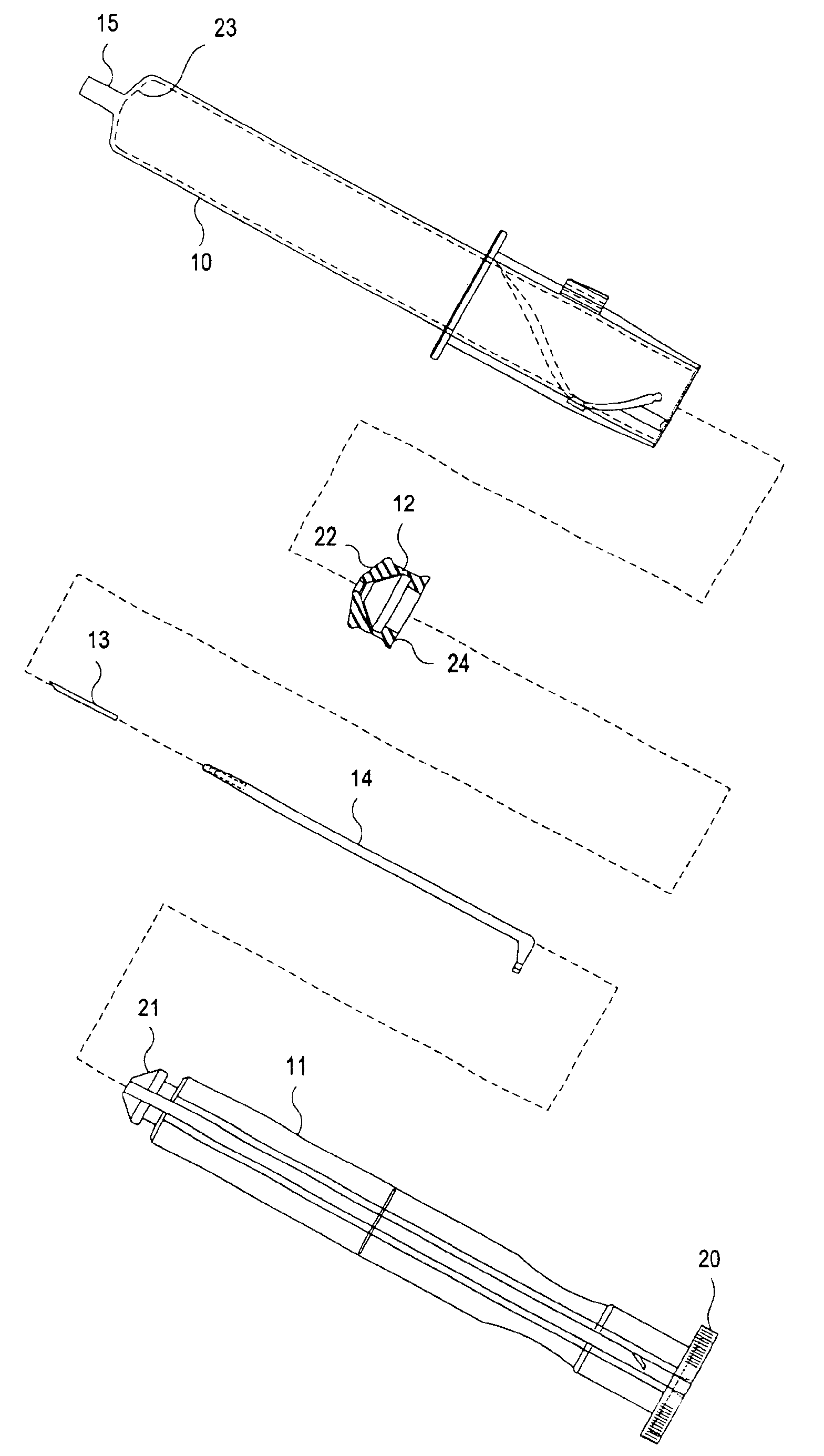
图1是用来实施本发明的注射器组件的局部分解图;Figure 1 is a partially exploded view of a syringe assembly used to practice the present invention;
图2是包括在图1组件中的针托的部分剖面的侧视图;Figure 2 is a side view, partly in section, of a needle holder included in the assembly of Figure 1;
图3是图2中针托远端部分放大的部分视面,部分剖面图;Fig. 3 is an enlarged partial view and partial cross-sectional view of the distal part of the needle holder in Fig. 2;
图4是图1中组件的柱塞的放大侧视图;Figure 4 is an enlarged side view of the plunger of the assembly of Figure 1;
图4a是图4中大致沿4a-4a线截取的剖面图;Figure 4a is a cross-sectional view taken approximately along
图5是图4中柱塞的端视图;Figure 5 is an end view of the plunger in Figure 4;
图6是图4中大致沿6-6线截取的剖面图;Fig. 6 is a cross-sectional view roughly taken along line 6-6 in Fig. 4;
图7与8是图4中柱塞的端盖的两种可替换形式的放大剖面图,而图9则是其端视图,Figures 7 and 8 are enlarged sectional views of two alternative forms of the end cap of the plunger of Figure 4, and Figure 9 is an end view thereof,
图10是图1所示注射器组件的放大侧视图,此时的针托处于推进位置而柱塞则处于其全程推进位置;Figure 10 is an enlarged side view of the syringe assembly shown in Figure 1 with the needle holder in its advanced position and the plunger in its fully advanced position;
图11是图9中组件的针筒部分的放大部分侧视图;Figure 11 is an enlarged partial side view of the barrel portion of the assembly of Figure 9;
图12是大致沿图11中12-12线截取的视图;Figure 12 is a view roughly taken along line 12-12 in Figure 11;
图13是图1中组件的锁定片的放大端视图;Figure 13 is an enlarged end view of the locking tab of the assembly of Figure 1;
图14是图13中锁定片的侧视图;Figure 14 is a side view of the locking piece in Figure 13;
图15与16是本发明的注射器组件的示意图,用来说明此柱塞轴向运动的有效范围,此时的针头已被全程推进;15 and 16 are schematic diagrams of the syringe assembly of the present invention, used to illustrate the effective range of axial movement of the plunger, and the needle at this time has been fully advanced;
图17与18是此注射器组件的示意图,表明了柱塞相对于针筒轴向运动的有效范围,此时的针托处于回撤位置,而针头已由针筒掩藏;Figures 17 and 18 are schematic diagrams of the syringe assembly, showing the effective range of axial movement of the plunger relative to the barrel, when the needle holder is in the withdrawn position and the needle is hidden by the barrel;
图19是此注射器组件的部分侧视图,说明用来将柱塞与针托同针筒相组合的部分程序,Figure 19 is a partial side view of the syringe assembly illustrating part of the procedure used to combine the plunger and needle holder with the barrel,
图20是大致沿图19中20-20线截取的部分剖面图;Figure 20 is a partial cross-sectional view roughly taken along line 20-20 in Figure 19;
图21至23是在此针筒上另一锁定片的视图;Figures 21 to 23 are views of another locking piece on the barrel;
图24是用来实施本发明的图1-20的注射器的组件的OTN导液管以及此组件一部分的放大横剖图;而24 is an enlarged cross-sectional view of an OTN catheter and a portion of the assembly of the syringe of FIGS. 1-20 used to practice the present invention; and
图25是示明OTN导液管另一实施形式的与图24类似的横剖图。Fig. 25 is a cross-sectional view similar to Fig. 24 showing another embodiment of the OTN catheter.
本发明有两种改型和替代形式,它的具体实施形式业已用举例方式于附图中示明,这里将对其详细说明。但应认识到,这样不是用来把本发明限制到所公开的具体形式中,相反,本发明将包括属于其附权利要求书精神与范围内的所有改型、等同形式与替代形式。There are two modifications and alternative forms of the invention, the embodiment of which has been shown by way of example in the drawings and which will be described in detail here. It should be understood, however, that such is not intended to limit the invention to the particular forms disclosed, but on the contrary, the invention is to cover all modifications, equivalents and alternatives falling within the spirit and scope of the appended claims.
下面将说明本发明的几种不同特点,而这些特点的各种排列与组合结果将导向其它的实施形式。Several different features of the invention are described below, and various permutations and combinations of these features lead to other embodiments.
现在参看附图,其中示明的注射器组件包括针筒10、柱塞11、空心柱塞盖12、皮下注射针头13以及针托14。针筒10是一空心柱状件,在其远端终止于一空心锥状的嘴15。通向此嘴15的有一锥状或圆锥状壁部23。或者,此针筒10可具有一直通其邻近端部6的恒定的内径与外径。嘴15的内部与针筒10的空心内部通道。在靠近针筒10邻端处有一向外延伸的凸缘17,便于使用者需使柱塞11相对针筒10运动时由其手指抓住此针筒。必要时可使针筒在凸缘17远侧上的一部分外表面如下所述取带细齿的形式,以有助于此针筒与柱塞相对转动时握住针筒。管件10的近端16是敞开的。Referring now to the drawings, there is shown a syringe assembly comprising a
针筒10的近端16有一个通过其壁部的螺旋槽19。下面可以看到,此螺旋槽19为针托14与皮下注射用针头13提供了回撤轨道。螺旋槽19延伸有足够的长度,以容许针托14能回撤以将针头10的整个长度全拉进针筒10内的一段距离,下面将对此作更详细地说明。为了能不太减弱针筒10远端16壁部的强度,螺旋槽16绕针筒10的圆周延伸不超过360°。在图示的实施形式中,螺旋槽19绕针筒10的圆筒延伸约270°。槽19的延伸范围小于270°并不背离本发明。The
针筒10的外表面最后标有分度(未示明),以表明液体在此针筒内所占有的体积量。这些分度考虑到了内部部件如针托14的体积。The outer surface of the
柱塞11的近端构成了可为使用者握住让柱塞11相对针筒10作直线或旋转运动的捏手20。捏手20的周边带有小齿便于将它抓住来转动柱塞。柱塞11的远端形成了一个可与橡胶制空心柱塞盖12配合的头部21。弹性盖12的外径在中央部减小,使得上述盖能只在其端的可挠性边缘处与针筒10的内壁配合。盖12的配合端部的直径略大于针筒10的内径,以使此盖能牢靠地压靠针筒的内壁而在盖/筒的界面处形成气密与液密式密封。盖12的内边缘与针托14的外表面形成类似的密封接触。盖12的内边缘上为此可设置有缝的阀12a(参看图6-8),即在针头13通过相对其外表面密封。盖12的远端22是锥形的,以在柱塞11完全进到针筒10内的与针筒内表面的锥形远端23一致。The proximal end of the
柱塞11的头部21所取的构型能紧配合到空心柱塞盖12内。以此盖部12锁定到柱塞的头部21上,此盖的平的近端24便在柱塞头部21的底座上抵靠一圆盘25的平表面。由于柱塞盖12与针筒10以及与针托14之间的气密与液密密封,柱塞11在针筒10内的推进运动便在此柱塞盖12与针筒10的远端间的针筒内部形成了压力。类似地,柱塞11的回撤运动则在针筒内的这一对应部分中形成了部分真空。或者可使用一种弹性的针筒,它与改形成载有一中央O形弹性密封圈的刚性柱塞板25接触。The
皮下注射用针头13安装于可分地联锁到针筒10的细长针托14的远端上。在使用此注射器组件之前,针头13由护罩(未图示)盖住,防止此针头扎刺和保持其在使用前的消毒性。针头13与针托14的远端都是空心的。空心针头13的内部与针托14的空心远端的内部通过。此针托14还通过其空心部侧壁中的孔26与针筒10内部通连(图2与3)。在因此注射器组件来注入药剂或抽出血液之前和之中(以后将此称作为“正常应用”),孔26位于针筒嘴15的底座处。孔26允许血液或药物通过针托14与针头13进出针筒10。这样的布置形式使得液体能保留于注射器内的静空间减至最小。A
在此注射器组件正常使用期间,针托14是锁定到针筒10上的,而柱塞11及其盖12则可以自由地沿针托作纵向地来回滑动。针托14包括一L形杆,此杆具有沿轴向延伸包含孔2b的纵向体部31,以及在此杆部近端沿径向横过针筒10的横臂32。During normal use of the syringe assembly, the
为使柱塞11和针托14间能沿纵向有相对的滑动,此针托安装于作为柱塞16整体的一部分形成的纵向槽33内。有多个相分开的弹性掣子或制动件34(图4与4a)从槽33的相对壁部由内部突出以将针托14保持在槽33内。这些掣子或制动件34在将针托14插入槽33中之际偏转,而在此针托已然就位后即弹回到它们的原始位置。构成槽33相对壁部的侧翼60与62一直延伸到针筒10的内壁(参看图10),由此限制着针托的横臂32相对于柱塞11作任何角位移或转动。这就是说,柱塞11与针托14只可以相互一致地转动,尽管它们可以相互独立地沿纵向自由运动。在此针托的近端,锁定掣子75(见后述)将所述臂与柱塞锁定到一起,防止在完成回撤作业后它们作相对运动。To allow relative longitudinal sliding between the
为了将针托14锁定到针筒10上,针托14远端部的外表面依特殊的构型无缝横压成与针筒嘴15的内壁上的相辅锥面15a相匹配的锥面14a。这两个锥面14a与15a通常称作为锁定路厄氏锥,而此锥角(一般用直径的百分率表示)通常称之为锁定锥角。在最佳实施形式中,使用6%的锥角。In order to lock the
在装配带针头的注射器之际,锁定面15a与14a在柱塞11与针托14通过针筒的敞口近端插入此针筒内时相配合。所形成的锁定路厄式锥只当同时施加轴向力与旋转力才能松释。During assembly of the needled syringe, the locking surfaces 15a and 14a cooperate when the
针托14的近端也通过横臂32锁定于针筒10上。臂32沿径向延伸到柱塞之外,并配合到螺旋槽19内。臂32可以在螺旋槽19的远端锁定到针筒10上,而在这样锁定后,可允许柱塞11只作往复式直线运动,形成抽出药剂或血液的真空,以及形成用来将药剂通过皮下注射用针头输入送给病人的压力。当臂32锁定到槽19的任一端上时,柱塞11便不能在针筒10内转动。当臂32在槽19的近端锁定于掣子75中,就使得整个注射器不能转动。The proximal end of the
当用户需要在针筒柱塞组件内撤出皮下注射用针头时,用于启动一机械掣子使臂32松开,由此允许柱塞11相对针筒10沿着螺旋槽19转动,这种相对转动回撤并锁定在此针筒-柱塞组件内的针头-针头组合体。为使此针头与针托移动到回撤位置,柱塞11则可处于任何所需位置,例如处于希望将血液或药物保持于此注射器内的位置。When the user desires to withdraw the hypodermic needle within the syringe plunger assembly, a mechanical detent is used to release the
图1以及图10-14中所示的最佳实施形式的闩锁机构50包括一有纵向槽的小片51,后者安装成用来在针筒10外壁上一短的纵向轨道52上滑动。锁片51的槽53的形状能与轨道59的外表面匹配,使此锁片51能在轨道52上前后滑动。锁片51的外表面54带有小齿,便于它由用户的手指或大姆指驱动。The
锁片51在其槽53内还形成一小的凹坑56。凹坑56的尺寸与位置在横臂32位于螺旋槽19的远端部而针头13处于其全程延伸的位置时,能用针托14的横臂32的终端部配合。这样就能防止锁片沿轨道52滑入近端方向。在需要撤出针头时,通过由手施加适当的力来回撤锁片51就能解脱上述配合。The locking
通过使锁片51沿轨道52作直线运动就能打开或关闭闩锁50。在正常使用中,横臂32位于螺旋槽19的与凸缘17紧邻的远端,而锁片51即进到轨道52上将臂32保持于槽19的远端。这样就把针托14锁定于正常作业方式,其中只允许柱塞11作往复直线运动。由于锁片51保持臂32不动,针托14便不能转动,因而不能沿螺旋槽19行进来将皮下注射用针头13回撤。或者可设置一由活铰链61连接到针筒10上的铰接锁片59(图21-23)。锁片59再一通孔63用来将横臂32与槽19的远端接合。针筒10外壁上的掣子65在与针托14的横向臂32配合时可将锁片保持就位。The
当需要回撤针头时,可将锁片51沿轨道52撤向此注射器的近端,允许通过臂32沿螺旋槽19的运动使柱塞11转动面回撤针托14。螺旋槽19的近端最好包括一键孔型的锁定件19a(图11)在针托已完全回撤后将臂32的端部锁定就位。图11中还示明了针托14的横臂32在相对于螺旋槽19转过90°、180°与270°时的近似位置。从邻近处升到螺旋槽19上的针托14进入键孔19a并通过角形掣子75,卡搭地卡入锁定位置。When the needle needs to be retracted, the locking
再来参看图4与9以及图19与20,可以看到柱塞11有许多依基本是90°的间隙沿径向朝外延伸的肋棱。第一对这样肋棱60,62界定了用来保持如上所述的针托14的纵向槽33。沿径向相对上述肋棱60与62突出有另一根肋棱64,而在与肋棱60与62突出有另一根肋棱64,而在与肋棱60、62与64正交的平面中则形成了另一对沿径向相对延伸的肋棱66与68。根据本发明的一种最佳实施形式,后一对肋棱66与68包括有在其近端处的沉凹表面70、72。Referring again to FIGS. 4 and 9 and FIGS. 19 and 20, it can be seen that the
如图10所示,柱塞11中一横向的矩形槽110构成了用来形成掣子75的模具芯棒用的通道槽,而柱塞头部20中的孔120(图5)则提供了在最初装配注射器(在针托业已卡合到槽33的掣子34之下以后)时,用来将针托14沿纵向推入针筒10内的工具用的通道。As shown in Figure 10, a transverse rectangular groove 110 in the
参看图19与20,其中的柱塞11已相对针筒10部分地回撤,而肋棱66与68的凹陷表面70和72则在例如由姆指与食指间加压使针筒10的敞开端压引一起时为此针筒的近端提供了一个减压空间。从图20中可以清楚看到,这一作用瞬时地使针筒10的敞开的近端略畸变成椭圆形,得以让最初插入的针托14的横臂部32通过针筒10的敞开的近端而进入螺旋槽19中。在针筒10端部中的分度凹座76(图11)在装配时将针托14保持在正确的角度位置,同时有一浅槽77(图1 1)用来在针筒瞬时畸变到它的椭圆形时进一步方便将针托14插入针筒1 0内。当针筒10上的压力松释后,针筒便回复到它的圆横剖面形而使横向臂32与螺旋槽19配合。Referring to Figures 19 and 20, the
应该看到,当把锁片51回撤而松开臂32时,柱塞可以处在任何的所需的纵向位置。这就是说,柱塞可以完全推进、完全回撤或是处在任何中间位置。这样的优点在于能在只把一部分药剂注入到病人体内后根据需要而撤出针头,或者可以根据需要把从病人身上抽出的部分血样保持于注射器中。为了防止在撤出针头时使注射器中盛放的任何流体流出,可在嘴15的端部设置胶乳密封剂(未图示)或可以利用针头罩78(图18)。It should be appreciated that when
为了在针托14的回撤运动中将臂32的端部保持于螺旋槽19内,在柱塞11上设有一整体的圆形保持板55。板55的直径与针筒10的内径匹配。有助于使针筒10的内壁保持所需的圆形。使用中作用于针筒壁部上的应力会改变其所需的圆形,而要是这样变形过大,臂32就会从螺旋槽19中逸出。但当把这种保持板55支撑于针筒10的内壁上,就能防止这种过量的畸变而可确保将臂32保持于螺旋槽19内。自然,除保持板55外,柱塞上的那些纵向肋棱也相互以约90°的间隔在针筒10的内壁上滑动,这样又进一步保证了此针能保持其所需圆形结构。In order to retain the end of the
在针筒10的设计中还可有许多其它的特点来帮助保持针筒10的形状,特别是在螺旋槽19的区域中能进一步有助于将臂32保持到螺旋槽19内。这些特点之一是对螺旋槽19本身的设计,即如前面所述,使其绕针筒周边延展的范围不超过360°。在所示实施例中,此螺旋槽只延展成绕针筒10的周边约270°。槽19的延展范围甚至可以小于270°也不背离本发明的精神。此外,轨道52与径向相对类似隆起的肋棱58则是成整体地形成在针筒10的近端部侧壁上,且最好是从针筒的近端沿纵向到凸缘17。这些隆起的肋棱52、58还有助于针筒10这部分结构的整体性与刚性。通过增加针筒壁在这一邻区中的厚度或是使针筒中包含了此螺旋槽的这一段应用不同的材料,可以获得另外的增强效果。在肋棱58的适当部位上设置一通槽57,就可在臂32沿螺旋槽19这部分滑动时使此臂的端部能由此通过。There may also be a number of other features in the design of the
在注射器组件的正常使用中,针筒10与针托14保持不动。而柱塞11则可相对于针筒10与针托14沿纵向自由运动。如图9所示,柱塞11的推进运动受到柱塞盖12与针筒10端壁接触的限制。柱塞11的回撤运动则受到柱塞盘25与臂32接触的限制。必要时,可将一内部环79(图11)设于针筒10的内表面上与螺旋槽19远侧上的盘25贴合,用以防止柱塞作进一步后撤和保护液体不通过针筒壁中的螺旋槽19漏泄。During normal use of the syringe assembly, the
针托14借助其远端部与针筒嘴15间的楔式锁定形式以及横臂由锁片51所作的强制或应变的锁合而锁定到针筒10上。或者,此针托可由本申请人以前的美国专利US 5643222所详述的,通过螺旋连接锁合到针筒嘴之上。柱塞11也可相对针托14沿纵向移动,因为针托在此方向上并未锁定于柱塞上。横臂32为锁片51的锁定防止了柱塞15及针托的转动,同时也防止了柱塞意外地拉出。只要是针托的横臂32为锁片51锁定此注射器组件便处于其正常工作方式下。The
在注射器组件正常使用之后,针头13可以回撤到柱塞11与针筒10之内。为此要求针托14在针筒10内朝此针筒近端作轴向运动,而这又要求针托14能松释开而沿螺旋槽19运动。这样,引发了针托14的回撤,而通过锁片51的回撤使臂32松释开。After normal use of the syringe assembly, the
在锁片51已回撤后,使转动柱塞捏手20使柱塞11依顺时针方向(从针筒近端观察)相对此针筒转动。随着柱塞的转动,针托14便与其一致地转动,这是因为臂32被固定在其中的针托已安装在柱塞上的槽33的相对平行壁部之间。针托14相对于针筒的转动,(1)通过作用于臂32上的螺旋槽19壁部上的凸轮式带动作用使针托回撤到柱塞内,(2)由于作用于锥面15a与14a上的旋转力与纵向力合成的结果使得锁定的路厄氏锥在针筒嘴15的远端松释开。随着转动的继续,臂32横切螺旋槽19的整个长度。由此使整个针托14在柱塞11内通过一相应的轴向距离回撤(参看图17)。自然,针尖13与针托14在一起回撤,从而如图17所示此针头便完全回撤到针筒嘴15与柱塞11之内。After the
在所示实施例中,螺旋槽19形成在针筒10的近端部中。此螺旋槽最好沿其长度有恒定的曲率,且如以前所述其延展程度最好绕针筒10的周边约≤270°。这里所示的注射器不需比常规的注射器更长,这是因为传统的注射器制造成比所需的长时是为了提供大于所述的流体客体,用以避免柱塞不经意撤出和导致注射器内盛物溢出。附加的管件长度也适合把螺旋槽19容纳于柱塞捏手和指形凸缘之间的空隙内。这样,本发明可把针筒长度在这一区域的延伸部分用作针头回撤机构。In the illustrated embodiment, a
在螺旋槽19的远端,臂32的端部使掣子75作实质性的弯曲并卡合入由槽19的壁形成的键孔形掣子凹口中,使得用户能在针头回撤到终端时感到卡嗒声。这种锁定作用是自动的。此时要是用户企图按相反方向转动捏手就会遇到极大的阻力。这种安全特点防止了针头返回到超过针筒嘴终端,阻止了再次使用此注射器的企图。At the distal end of the
从槽33的近端的内壁突出,形成一朝此近端向内扩张的锁定掣子75(图4),以防柱塞11在针托14已回撤后从针筒10中撤了同,臂32在其回撤经过掣子75时使此掣子偏转,然后臂32即与此掣子的近端结合,而阻止任何打算把柱塞11回撤超过针托14的企图。掣子75对臂32的这种锁定也防止了柱塞进一步转动。柱塞捏手20同样制止了臂32从而也制止了针托14与针头13沿近向返回的运动。Protrude from the inner wall of the proximal end of the
在使此注射器组件工作时,从针头13除下防护罩78(图18),将所需数量的药剂吸入针筒10中。然后确定病人身体上的注射点,用消毒溶液清洗的皮肤。在经皮肤将针头插入病人体内后,通过吸入少量的血液到此透明针筒10内来肯定此针头定位在血管中然后柱塞11前行迫使药物从针筒10注入血管。在注射完药剂后,将针头13从病人身上抽出,片51缩回而使臂32松开,然后顺时针转动柱塞捏手20,直到用户感觉到臂32卡合入螺旋槽19近端的掣子凹口19a中。螺旋槽19也可另取要求反时针定向而非顺时针走向的构型来转动柱塞捏手20。在针头13完全回撤入针筒10内,此注射器组件即可整个地抛弃。In operating the syringe assembly, the shield 78 ( FIG. 18 ) is removed from the
从上述可知,这种注射器组件实现了传统注射器的全部功能,而在注射结束后则可把皮下注射用针头掩藏于针筒10内。这种注射器组件对于一个固定的病人可以通过柱塞11在针筒10内往复地纵向运动作任意多次的接受和分数药剂。此注射器组件的另一个优点是它的设计防止了它在正常使用中致柱塞11从针筒10滑脱。It can be seen from the above that this syringe assembly realizes all the functions of a conventional syringe, and the hypodermic needle can be hidden in the
本发明的这种注射器组件易于制造,成本低廉,且便于在有关领域中应用。此组件的各个部分可由常规的塑料模制成形,同时可应用能直接购到的金属针座。通过注塑诸如聚丙烯的医疗等级的聚合物可以制成这些塑料部件。此柱塞的密封件或罩可由天然或合成的弹性聚合物模制。针筒壁部内的螺旋槽可利用具有与模具芯销接触的螺旋升坡的滑动件形成。所用模具直到此针筒从此模具的芯销上退下之后才打开,以保持此模压出的螺旋轨道的完整性。在柱塞槽33内的掣子则是通过突入到此槽的模芯内的销子模制成的。The syringe assembly of the present invention is easy to manufacture, low in cost, and convenient to be applied in related fields. The various parts of the assembly can be molded from conventional plastic, while off-the-shelf metal headers can be used. These plastic parts can be made by injection molding medical grade polymers such as polypropylene. The seal or cap of the plunger can be molded from natural or synthetic elastomeric polymers. The helical groove in the barrel wall can be formed with a slide having a helical ramp in contact with the core pin. The mold used is not opened until the barrel is withdrawn from the core pin of the mold to maintain the integrity of the molded helical track. The detents in the
最终形成的组件是很紧凑的,这是因为针托14直接回撤到柱塞11本身之内,于是柱塞11不必为使针头回撤而全部撤回。这种注射器组件在使用后抛弃时在那么多废物中所占的量是微乎其微的。由于针头13已经通过转动此组件近端处的柱塞捏手20而回撤,从而用户的手不会进到针头尖梢的邻区,得以在撤出作业中使针头扎刺的可能性减至最少。此外,这种注射器组件所用到的部件与常规注射器的基本相同,并不要求另加护、罩、套、弹簧等来掩藏使用后的针头。The resulting assembly is very compact because the
图24描述了一种OTN导液管组件,它包括OTN导液管80和图1-20中的注射器组件(只示明了它的远端部分),其中安装有皮下注射用针头13。在图24所示的实施形式中,OTN导液管80是聚合物制的导液管。上面安装一细长的梢部82。在使用OTN导液管组件之前,将OTN导液管80的近端表面84共轴地安装到针筒嘴15之上,而让皮下注射用针头13经嘴15与OTN导液管80突出。导液管80的细长梢部82推到针头13之上。使用之前,即在将针头13与导液管梢部82插入血管之前,此针头13与导液管梢部82都由一可除去的盖(未图示)封罩。FIG. 24 depicts an OTN catheter assembly comprising an
导液管80最好包括一在内部的阀如狭缝阀86以限制流体的流过。在OTN导液管组件的正常使用之中或之前,通过嘴15的外表面115和导液管80内表面81两者上的锁定路厄氏锥,此OTN导液管80便保持接合于此注射器组件的嘴15之上。在刺入病人的血管而把OTN导液管80的梢部82插进其血管后,针托14及其上安装的针头13便依前述方式回撤。在此回撤后的位置上,针托14即如先前所说不能回复地锁定于针筒之内。然后通过同时转动与回撤此注射器使其与导液管脱开,得以松释由表面115与81所形成的锁定路厄氏锥。然后将OTN导液管80锥入血管中,用粘合带将其固定于皮肤上。
由表面115与81所形成的锁定路厄氏锥是用来使注射器与OTN导液管借机械的方法成为统一体,便于将加到此注射器上的力直接传递给皮下注射用针头13和导液管80。松释开此锁定路厄氏锥便能分离上述统一体,而能允许将注射器以及撤回的针头13从导液管80上取下。The locking Luer cone formed by
在扎刺血管时,可以通过观察到有血液因毛细管作用进入导液管80来判定针头13上导液管梢部82定位到此血管中。但是也能通过使柱塞11相对于注射器针筒10作部分回撤来判定在此针筒内发生反流以确定在针头13与血管间形成了连续体。针托14的边孔26朝上与这样形成的反流室通连。借助血液经由针托14的边孔26进入这一反流室来判定对血管的合适插入。When puncturing a blood vessel, it can be determined that the
在使用OTN导液管-注射器组件时,先要对病人的皮肤作处理并要使周边的血管凸起。在灭菌等措施之后,以针头13与导液管梢部82穿刺血管,并通过导液管下颜色的变化或导液管中或是反流室中血液的外观来判断针头尖梢的定位。一旦针头定位好后,便依前述方式回撤针托。在血管中推进并保持OTN导液管孔的同时,除下此注射器组件而使静脉血管与导液管80连接。最后,用粘合带将导液管80固定到病人的皮肤上。When using the OTN catheter-syringe assembly, the patient's skin is first prepared and surrounding blood vessels are raised. After sterilization and other measures, use the
如图25所示,能够将带有狭缝阀86的OTN导液管80代之以具有两个正交配置体部90a和90b的OTN导液管组件90,这两个体部由一旋转型的三通球阀机构92有效地连接到细长的导液管梢部82上,后者与图24-26中导液管80上的相同。As shown in FIG. 25, the
上述新颖的和改进了的注射器组件具有许多优点:The novel and improved syringe assembly described above has many advantages:
柱塞槽33中的掣子34提高了针托运动的精度。例如,针头在柱塞槽33中笔直的轴向回撤避免了针头的弯曲和穿刺筒腔。这种组件不需延伸注射器的全长,也不需用破坏其柱塞之类的特殊措施来防止其再度使用。The
螺旋槽19是在针筒本身中模制出的,因而能与针托可靠地配合而不需其它的工艺或复杂的手段。The
通过将螺旋槽19的周线从360减少到270°或更少。可以增强针筒10的近端部分16。可在针筒中添设直线式的增强肋52、50用来增强强度。By reducing the circumference of the
本发明中的部件(除了锁片51)数与常规注射器中的相同,能保持成本低廉。The number of parts (except for locking tab 51) in the present invention is the same as in conventional syringes, keeping the cost low.
应用了滑动的针托来取代通常的在针筒嘴上的针托,这样消除了相关的净空间和留剩在此针筒嘴中与凹针托中的废弃药物量。A sliding needle holder is used instead of the usual needle holder on the mouth of the syringe, which eliminates the associated headroom and the amount of waste drug remaining in the mouth of the syringe and in the recessed needle holder.
注射器的作业是单向式的因而可使意外的误用减至最低限度,也就是针托一旦回撤后便锁定在位,因而针头不能再次伸出。The operation of the syringe is one-way so that accidental misuse is minimized, ie the needle holder is locked in place once retracted so the needle cannot be re-extended.
注射器的作业特别安全,因为在正常的使用方式和回撤的作业方式中,此注射器各个部件的操作都是在此注射器的近端或近端附邻即充分避开针头处进行的。Handling of the syringe is particularly safe because the operation of the various parts of the syringe is at or near the proximal end of the syringe, ie well clear of the needle, during normal use and retracted operation.
当针托通过转动柱塞而回撤时,锁定与禁用作业都是自动进行的,并能通过掣子75产生的可听见的卡嗒声可靠地指明。柱塞的回拉也为柱塞中的掣子75所锁定,同时针托在螺旋槽中的回驶也为此掣子75以及柱塞捏手与针筒边缘和掣子凹口19a的干扰接触而制止。Locking and disabling operations are both automatic and positively indicated by an audible click of the
在罕见的事故中,当只把一部分药剂给予了病人时,带有余剩药剂的注射器能通过使针托经转动回撤而成为安全的,同时在针筒嘴上加盖便可防止漏泄。In the rare event when only a portion of the dose is administered to the patient, the syringe with the remaining dose can be secured by turning the needle holder back and capping the mouth of the barrel to prevent leakage.
应该注意到,上述的注射器组件可以用来分配药物或用作血液收集装置。它也可以用来如上所述放置上一OTN导液管。It should be noted that the syringe assembly described above may be used to dispense medication or as a blood collection device. It can also be used to place an OTN catheter as described above.
尽管本发明业已参照一或多种特殊实施方式作了描述,但内行的人可以认识到,在不背离本发明的精神和与范围的前提下是可以对之作出各种变化的。每一种这样的实施形式及其显而易见的变动形式都应视作为属于后附权利要求书所陈述的本发明所要求权利保护的精神与范围之内。Although the invention has been described with reference to one or more specific embodiments, those skilled in the art will recognize that various changes may be made therein without departing from the spirit and scope of the invention. Each of these implementations and obvious variations thereof should be considered within the spirit and scope of the invention as set forth in the appended claims.
Claims (31)
Applications Claiming Priority (2)
| Application Number | Priority Date | Filing Date | Title |
|---|---|---|---|
| US08/972548 | 1997-11-18 | ||
| US08/972,548 US6117112A (en) | 1997-11-18 | 1997-11-18 | Single-use safety syringe |
Related Child Applications (1)
| Application Number | Title | Priority Date | Filing Date |
|---|---|---|---|
| CNB2004100905791A Division CN1315545C (en) | 1997-11-18 | 1998-11-18 | disposable safety syringe |
Publications (2)
| Publication Number | Publication Date |
|---|---|
| CN1218695A CN1218695A (en) | 1999-06-09 |
| CN1183976C true CN1183976C (en) | 2005-01-12 |
Family
ID=25519795
Family Applications (2)
| Application Number | Title | Priority Date | Filing Date |
|---|---|---|---|
| CNB2004100905791A Expired - Fee Related CN1315545C (en) | 1997-11-18 | 1998-11-18 | disposable safety syringe |
| CN98122408.3A Expired - Fee Related CN1183976C (en) | 1997-11-18 | 1998-11-18 | disposable safety syringe |
Family Applications Before (1)
| Application Number | Title | Priority Date | Filing Date |
|---|---|---|---|
| CNB2004100905791A Expired - Fee Related CN1315545C (en) | 1997-11-18 | 1998-11-18 | disposable safety syringe |
Country Status (8)
| Country | Link |
|---|---|
| US (1) | US6117112A (en) |
| EP (1) | EP0916354B1 (en) |
| JP (1) | JPH11226125A (en) |
| CN (2) | CN1315545C (en) |
| AU (1) | AU737080B2 (en) |
| CA (1) | CA2254174C (en) |
| DE (1) | DE69812542T2 (en) |
| IN (1) | IN189016B (en) |
Cited By (1)
| Publication number | Priority date | Publication date | Assignee | Title |
|---|---|---|---|---|
| CN104721912A (en) * | 2015-03-26 | 2015-06-24 | 江苏阳普医疗科技有限公司 | Disposable blood vessel puncture-proof intravenous infusion needle |
Families Citing this family (51)
| Publication number | Priority date | Publication date | Assignee | Title |
|---|---|---|---|---|
| US6280401B1 (en) * | 1993-08-23 | 2001-08-28 | Sakharam D. Mahurkar | Hypodermic needle assembly |
| JP4593714B2 (en) * | 2000-02-10 | 2010-12-08 | 株式会社根本杏林堂 | Syringe outer cylinder, syringe holder, syringe piston and piston holder |
| GB0003790D0 (en) | 2000-02-18 | 2000-04-05 | Astrazeneca Uk Ltd | Medical device |
| US6530903B2 (en) | 2000-02-24 | 2003-03-11 | Xiping Wang | Safety syringe |
| US20040030294A1 (en) | 2001-11-28 | 2004-02-12 | Mahurkar Sakharam D. | Retractable needle single use safety syringe |
| USD470234S1 (en) | 2001-12-26 | 2003-02-11 | Sakharam D. Mahurkar | Safety syringe |
| USD474838S1 (en) | 2002-01-24 | 2003-05-20 | Sakharam D. Mahurkar | Safety syringe |
| US6764465B2 (en) * | 2002-06-24 | 2004-07-20 | Long Hsiung Chen | Syringe with retractable needle and safety lock |
| IL157981A (en) | 2003-09-17 | 2014-01-30 | Elcam Medical Agricultural Cooperative Ass Ltd | Auto-injector |
| DE10348603A1 (en) * | 2003-10-20 | 2005-05-19 | Klinika Medical Gmbh | Cannula holder comprises an unlocking mechanism which is constituted so that after its operation the cannula and/or the adapter will fall into the cannula container |
| US7988664B2 (en) | 2004-11-01 | 2011-08-02 | Tyco Healthcare Group Lp | Locking clip with trigger bushing |
| US7226434B2 (en) | 2003-10-31 | 2007-06-05 | Tyco Healthcare Group Lp | Safety shield |
| US7468054B2 (en) | 2003-11-03 | 2008-12-23 | Becton, Dickinson And Company | Safety shield system for a syringe |
| US7101351B2 (en) | 2003-11-03 | 2006-09-05 | Becton, Dickinson And Company | Safety device for a syringe |
| US7497847B2 (en) | 2003-11-03 | 2009-03-03 | Becton, Dickinson And Company | Safety shield system for a syringe |
| US7344517B2 (en) | 2004-01-20 | 2008-03-18 | Becton, Dickinson And Company | Syringe having a retractable needle |
| US7604613B2 (en) | 2004-01-20 | 2009-10-20 | Beckton, Dickinson And Company | Syringe having a retractable needle |
| IL160891A0 (en) | 2004-03-16 | 2004-08-31 | Auto-mix needle | |
| US7828773B2 (en) | 2005-07-11 | 2010-11-09 | Covidien Ag | Safety reset key and needle assembly |
| US7905857B2 (en) | 2005-07-11 | 2011-03-15 | Covidien Ag | Needle assembly including obturator with safety reset |
| US7850650B2 (en) | 2005-07-11 | 2010-12-14 | Covidien Ag | Needle safety shield with reset |
| US8062252B2 (en) | 2005-02-18 | 2011-11-22 | Becton, Dickinson And Company | Safety shield system for a syringe |
| WO2006109272A2 (en) * | 2005-04-13 | 2006-10-19 | Coeur Inc | Syringe plunger jacket with expandable seal |
| US20060276747A1 (en) | 2005-06-06 | 2006-12-07 | Sherwood Services Ag | Needle assembly with removable depth stop |
| CA2550114C (en) | 2005-06-20 | 2013-11-19 | Sherwood Services, Ag | Safety shield for medical needles |
| US7731692B2 (en) | 2005-07-11 | 2010-06-08 | Covidien Ag | Device for shielding a sharp tip of a cannula and method of using the same |
| US7654735B2 (en) | 2005-11-03 | 2010-02-02 | Covidien Ag | Electronic thermometer |
| US9358348B2 (en) * | 2006-06-14 | 2016-06-07 | Covidien Lp | Safety shield for medical needles |
| EP2187997A1 (en) * | 2007-08-20 | 2010-05-26 | Global Medisafe Holdings Limited | Safety syringe with plunger locking means |
| WO2009042874A1 (en) | 2007-09-27 | 2009-04-02 | Tyco Healthcare Group Lp | I.v. catheter assembly and needle safety device |
| US8357104B2 (en) | 2007-11-01 | 2013-01-22 | Coviden Lp | Active stylet safety shield |
| EP2075029B1 (en) | 2007-12-20 | 2010-09-29 | Tyco Healthcare Group LP | Locking cap assembly with spring-loaded collar |
| NL2001702C2 (en) * | 2008-06-19 | 2009-12-22 | Addino B V | Injection syringe with possibility of needle storage. |
| CN105854135B (en) * | 2008-06-26 | 2019-11-01 | 贝克顿·迪金森公司 | It passively prevents from reusing syringe using retaining ring lock |
| ES2766253T3 (en) | 2008-09-18 | 2020-06-12 | Becton Dickinson Co | Medical Plunger Injector with Ratchet Function |
| US8864725B2 (en) | 2009-03-17 | 2014-10-21 | Baxter Corporation Englewood | Hazardous drug handling system, apparatus and method |
| BRPI0925003B8 (en) * | 2009-04-27 | 2021-06-22 | Becton Dickinson Co | passive reuse deterrent syringe that uses a tip lock |
| US7918821B2 (en) | 2009-05-05 | 2011-04-05 | Mahurkar Sakharam D | Universal safety syringe |
| BRPI0924659B8 (en) | 2009-06-26 | 2021-06-22 | Becton Dickinson Co | passive reuse prevention syringe using a flange lock |
| JP4981949B2 (en) * | 2010-05-07 | 2012-07-25 | 株式会社根本杏林堂 | Chemical solution injection system with buttock-enhanced syringe and automatic injection device |
| CN105498049B (en) * | 2011-03-17 | 2018-09-21 | 贝克顿·迪金森公司 | Medical injector with ratchet-type plunger |
| JP6178325B2 (en) | 2011-11-07 | 2017-08-09 | セーフティ シリンジズ, インコーポレイテッド | Contact trigger release needle guard |
| US9737686B2 (en) * | 2012-03-12 | 2017-08-22 | Becton, Dickinson And Company | Catheter adapter port valve |
| US10426932B2 (en) * | 2013-01-17 | 2019-10-01 | Toby Wexler | Method and apparatus for introducing an intravenous catheter |
| TWI675645B (en) * | 2018-03-26 | 2019-11-01 | 慈濟學校財團法人慈濟科技大學 | Rotating retractable safety needle |
| CN109498910B (en) * | 2019-01-15 | 2021-03-19 | 南昌爱美美容医院有限公司 | A medical syringe for preventing airflow pollution during use |
| WO2020194561A1 (en) * | 2019-03-26 | 2020-10-01 | 太平洋工業株式会社 | Valve |
| AU2019448614B2 (en) * | 2019-05-24 | 2025-04-17 | Becton, Dickinson And Company | Needle-tract assistant including components and methods thereof |
| EP3821925B1 (en) | 2019-09-18 | 2024-03-20 | KAISHA PACKAGING Private Ltd. | Device for locking a plunger rod of a syringe after use and preventing re-use of the syringe, and syringe assembly |
| USD948714S1 (en) | 2020-06-22 | 2022-04-12 | KAISHA PACKAGING Private Ltd. | Syringe plunger lock |
| CN114948742B (en) * | 2022-05-30 | 2026-01-23 | 江苏康宝医疗器械有限公司 | Split type O type circle intestinal feeder |
Family Cites Families (207)
| Publication number | Priority date | Publication date | Assignee | Title |
|---|---|---|---|---|
| BE541390A (en) * | 1955-10-18 | |||
| US2925083A (en) * | 1957-12-27 | 1960-02-16 | Clarence D Craig | Hypodermic syringe with hood for guarding and concealing the needle |
| US3610240A (en) * | 1967-06-13 | 1971-10-05 | American Hospital Supply Corp | Intravenous catheter apparatus with catheter telescoped inside puncturing cannula |
| DE1914749A1 (en) | 1968-03-26 | 1969-10-09 | Matburn Holdings Ltd | Transfusion device, especially intravenous catheter |
| US3658061A (en) * | 1970-11-10 | 1972-04-25 | Baxter Laboratories Inc | Needle guard |
| DE2415196A1 (en) | 1974-03-29 | 1975-10-16 | Hans Dr Zeidler | Intromission device for flexible insert into bodily cavities - has syringe type applicator containing viscous fluid |
| DE2507119A1 (en) | 1975-02-19 | 1976-09-02 | Kurt Dr Med Sokol | Sterile storage of vein catheter - incylinder of hypodermic syringe with cap closing tapping needle cone |
| US4068659A (en) * | 1976-07-12 | 1978-01-17 | Deseret Pharmaceutical Co., Inc. | Catheter placement assembly |
| GB2012919B (en) * | 1977-11-24 | 1982-05-19 | Wolf Gmbh Richard | Trocar sleeves |
| US4261357A (en) * | 1979-01-29 | 1981-04-14 | Critikon, Inc. | Catheter assembly for intermittent intravenous medicament delivery |
| US4245635A (en) * | 1979-01-29 | 1981-01-20 | Jelco Laboratories | Catheter assembly for intermittent intravenous use |
| US4274408A (en) * | 1979-03-26 | 1981-06-23 | Beatrice Nimrod | Method for guide-wire placement and novel syringe therefor |
| DE3042229C2 (en) | 1980-11-08 | 1983-10-27 | B. Braun Melsungen Ag, 3508 Melsungen | Insertion device for inserting elongated objects into blood vessels |
| US4424833A (en) * | 1981-10-02 | 1984-01-10 | C. R. Bard, Inc. | Self sealing gasket assembly |
| US4417886A (en) * | 1981-11-05 | 1983-11-29 | Arrow International, Inc. | Catheter introduction set |
| US4468224A (en) * | 1982-01-28 | 1984-08-28 | Advanced Cardiovascular Systems, Inc. | System and method for catheter placement in blood vessels of a human patient |
| US4425120A (en) * | 1982-04-15 | 1984-01-10 | Sampson Norma A | Shielded hypodermic syringe |
| US4529399A (en) * | 1983-05-03 | 1985-07-16 | Catheter Technology Corporation | Method and apparatus for placing a catheter |
| US4958622A (en) * | 1983-05-11 | 1990-09-25 | Selenke William M | Hypodermic syringe for taking and transporting a specimen |
| US4892525A (en) * | 1984-01-18 | 1990-01-09 | Synertex | Hypodermic needle protective barrel and cap packaging |
| US4732162A (en) * | 1985-10-18 | 1988-03-22 | Martell Medical Products, Inc. | Automatic and position-sensitive syringe and method for nonaspirating or aspirating obtaining of blood samples |
| US4735617A (en) * | 1985-11-08 | 1988-04-05 | Nelson Robert A | Hypodermic syringe needle guard |
| US4659330A (en) * | 1985-11-08 | 1987-04-21 | Robert Nelson | Hypodermic syringe needle guard |
| US4826488A (en) * | 1985-11-08 | 1989-05-02 | Nelson Robert A | Hypodermic syringe needle guard |
| US4631057A (en) * | 1985-12-17 | 1986-12-23 | Dolores A. Smith | Shielded needle |
| US4664654A (en) * | 1986-03-07 | 1987-05-12 | Strauss Eric C | Automatic protracting and locking hypodermic needle guard |
| US4931048A (en) * | 1986-04-07 | 1990-06-05 | Icu Medical, Inc. | Medical device |
| US4778453A (en) * | 1986-04-07 | 1988-10-18 | Icu Medical, Inc. | Medical device |
| USD298352S (en) | 1986-04-28 | 1988-11-01 | Burron Medical Inc. | Hypodermic needle guard |
| US4666435A (en) * | 1986-05-22 | 1987-05-19 | Braginetz Paul A | Shielded medical syringe |
| US4702738A (en) * | 1986-05-22 | 1987-10-27 | Spencer Treesa A | Disposable hypodermic syringe and needle combination having retractable, accident preventing sheath |
| US4801295A (en) * | 1986-05-22 | 1989-01-31 | Spencer Treesa A | Disposable hypodermic syringe and needle combination having retractable, accident preventing sheath |
| US4767412A (en) * | 1986-06-10 | 1988-08-30 | Seldoren Limited | Finger guards |
| US4693708A (en) * | 1986-10-16 | 1987-09-15 | Wanderer Alan A | Combination needle shield/needle guard device for a hypodermic syringe with a permanently attached needle |
| US4731059A (en) | 1986-10-14 | 1988-03-15 | Medical Safety Products, Inc. | Combination needle shield/needle guard device positively locked onto detachable needle assemblies for an evacuated blood collection system and a hypodermic syringe |
| US4846811A (en) * | 1987-01-29 | 1989-07-11 | International Medical Innovators, Inc. | Sliding sheath for medical needles |
| US4710170A (en) * | 1987-02-12 | 1987-12-01 | Habley Medical Technology Corporation | Anti-needle strike and anti-drug abuse syringe |
| US4747835A (en) * | 1987-02-19 | 1988-05-31 | Jeffrey Sandhaus | Safety device for hypodermic needles |
| US4762516A (en) * | 1987-03-05 | 1988-08-09 | Luther Medical Products, Inc. | Assembly of needle catheter protector |
| US4832696A (en) * | 1987-03-05 | 1989-05-23 | Luther Medical Products, Inc. | Assembly of needle and protector |
| US4828548A (en) * | 1987-03-16 | 1989-05-09 | Walter Gregory W | Safety catheter |
| CA1285441C (en) | 1987-03-17 | 1991-07-02 | Roy D. Mcnaughton | Mcnaughton syringe shield type b |
| US4782841A (en) * | 1987-04-07 | 1988-11-08 | Icu Medical, Inc. | Medical device |
| US4816024A (en) * | 1987-04-13 | 1989-03-28 | Icu Medical, Inc. | Medical device |
| US4767413A (en) * | 1987-04-20 | 1988-08-30 | Habley Medical Technology Corporation | Dental syringe having an automatically retractable needle |
| WO1988008315A1 (en) | 1987-04-22 | 1988-11-03 | Maxwell Edmund Whisson | A parenteral device |
| US4747831A (en) * | 1987-04-29 | 1988-05-31 | Phase Medical, Inc. | Cannula insertion set with safety retracting needle |
| US4731068A (en) * | 1987-05-01 | 1988-03-15 | Hesse John E | Non-reloadable syringe |
| US4742910A (en) * | 1987-06-22 | 1988-05-10 | Staebler Charles R | Needle sheath holder |
| US4874384A (en) * | 1987-07-13 | 1989-10-17 | International Medical Innovators, Inc. | Needle safety guard |
| US4747836A (en) * | 1987-07-17 | 1988-05-31 | Luther Medical Products, Inc. | Needle guard, and assembly |
| US4838871A (en) * | 1987-07-17 | 1989-06-13 | Luther Ronald B | Needle guard, and assembly |
| US4735618A (en) * | 1987-07-20 | 1988-04-05 | Henry E. Szachowicz, Jr. | Protective enclosure for hypodermic syringe |
| US4752290A (en) * | 1987-07-27 | 1988-06-21 | Schramm James J | Needle bearing medical device with three-position shield |
| US4826491A (en) * | 1987-07-27 | 1989-05-02 | Schramm James J | Needle bearing medical device with three-position shield |
| US4850961A (en) * | 1987-07-30 | 1989-07-25 | Wanderer Alan A | Indwelling placement device with guard |
| US5002536A (en) | 1987-08-17 | 1991-03-26 | Thompson John P | Guarded needle cover |
| US4746017A (en) * | 1987-08-18 | 1988-05-24 | Bristol-Myers Company | Safety container for glass vials |
| US4928824A (en) * | 1987-09-15 | 1990-05-29 | Barasch Stephen T | Hypodermic needle sheath protection shield apparatus |
| US4813938A (en) * | 1987-09-17 | 1989-03-21 | Raulerson J Daniel | Catheter introduction syringe |
| US4819659A (en) * | 1987-09-21 | 1989-04-11 | Icu Medical, Inc. | Blood withdrawal device with movable needle guard member |
| US4834717A (en) * | 1987-09-25 | 1989-05-30 | Habley Medical Technology Corporation | Disposable, pre-sterilizable syringe for a pre-filled medication cartridge |
| US4799926A (en) * | 1987-10-13 | 1989-01-24 | Habley Medical Technology Corporation | Syringe, having self-contained, sterile, medication applying swab |
| US4950252A (en) * | 1987-11-02 | 1990-08-21 | Luther Medical Products, Inc. | Single hand actuated locking safety catheter and method of use |
| US4863436A (en) * | 1987-11-03 | 1989-09-05 | Iatroban, Ltd. | Hypodermic needle with protective cover |
| US4813426A (en) * | 1987-11-09 | 1989-03-21 | Habley Medical Technology Corporation | Shielded safety syringe having a retractable needle |
| US4790822A (en) * | 1987-12-11 | 1988-12-13 | Haining Michael L | Retractable hypodermic safety syringe |
| US4887998A (en) * | 1987-12-14 | 1989-12-19 | Martin Catherine L | Hypodermic needle guard |
| US4826489A (en) * | 1988-01-14 | 1989-05-02 | Habley Medical Technology Corporation | Disposable safety syringe having means for retracting its needle cannula into its medication cartridge |
| US4808169A (en) * | 1988-01-14 | 1989-02-28 | Habley Medical Technology Corporation | Disposable safety syringe having means for retracting its needle cannula into its medication cartridge |
| US4842591A (en) * | 1988-01-21 | 1989-06-27 | Luther Ronald B | Connector with one-way septum valve, and assembly |
| US5171300A (en) | 1988-02-01 | 1992-12-15 | Medtech Group, Inc. | Disposable hypodermic syringe |
| US4986813A (en) * | 1988-02-01 | 1991-01-22 | The MadTech Group, Inc. | Disposable hypodermic syringe |
| US5019045A (en) | 1988-03-28 | 1991-05-28 | Lee Sang D | Hypodermic syringe with a locking needle assembly and syringe combination |
| US4915697A (en) * | 1988-03-16 | 1990-04-10 | Dupont Frank | Hypodermic needle assembly |
| NZ228388A (en) | 1988-03-22 | 1992-07-28 | Davsa Seventy Fifth Pty Ltd | Syringe with needle retractor |
| US5037400A (en) | 1988-03-30 | 1991-08-06 | Oakleaf Enterprises, Inc. | Apparatus for resheathing hypodermic needles |
| US4883469A (en) * | 1988-04-08 | 1989-11-28 | Glazier Stephen C | Guard assembly for hypodermic needle |
| DE8804656U1 (en) | 1988-04-08 | 1988-08-04 | Bader, Mohandes, 2350 Neumünster | Medical syringe |
| US4850976A (en) * | 1988-04-08 | 1989-07-25 | The Cloverline, Inc. | Combination sheath and foldable shield for hypodermic syringe needle |
| US4919656A (en) * | 1988-04-11 | 1990-04-24 | Biosurge, Inc. | Safety device for hypodermic syringe to prevent stick injuries |
| US4931040A (en) * | 1988-04-13 | 1990-06-05 | Habley Medical Technology | Safety syringe having a combination needle cannula and articulating hub for retracting said cannula into a medication carpule |
| GB2217991A (en) * | 1988-05-03 | 1989-11-08 | John Cole | Needle protection |
| US4897083A (en) * | 1988-05-09 | 1990-01-30 | Martell Michael D | Syringe needle guard |
| US5195992A (en) | 1988-05-13 | 1993-03-23 | Baxter International Inc. | Protector shield for needles |
| US4860742A (en) * | 1988-05-16 | 1989-08-29 | Medical Innovations Corporation | Assembly of wire inserter and lock for a medical wire |
| US4932940A (en) * | 1988-06-06 | 1990-06-12 | Walker Cedric F | Needle guard device |
| US5015241A (en) | 1988-06-20 | 1991-05-14 | Feimer Michael P | Safety system for hypodermic syringe and needle |
| US4915696A (en) * | 1988-06-20 | 1990-04-10 | Feimer Michael P | Safety system for hypodermic syringe and needle |
| US4909794A (en) * | 1988-06-24 | 1990-03-20 | Habley Medical Technology Corporation | Combination retractable needle cannula and cannula lock for a medication carpule |
| US5127910A (en) | 1988-06-28 | 1992-07-07 | Sherwood Medical Company | Combined syringe and needle shield and method of manufacture |
| US5217437A (en) | 1988-06-28 | 1993-06-08 | Sherwood Medical Company | Needle protecting device |
| US5147326A (en) | 1988-06-28 | 1992-09-15 | Sherwood Medical Company | Combined syringe and needle shield and method of manufacture |
| US5088988A (en) | 1988-06-28 | 1992-02-18 | Sherwood Medical Company | Combined dental syringe and needle shield |
| US5160326A (en) | 1988-06-28 | 1992-11-03 | Sherwood Medical Company | Combined syringe and needle shield |
| US5067944A (en) | 1988-07-05 | 1991-11-26 | Jerry Robles | Hypodermic needle guard |
| US4927417A (en) * | 1988-07-07 | 1990-05-22 | Schneider Medical Technologies, Inc. | Safety sleeve adapter |
| US5088987A (en) | 1988-07-19 | 1992-02-18 | Noonan Jr Thomas J | Syringe |
| US4828107A (en) * | 1988-07-25 | 1989-05-09 | Treesa Spencer | Disposable container for syringes |
| US4932946A (en) * | 1988-07-29 | 1990-06-12 | Shields Jack W | Hub-mounted, slit-elastic needle guard |
| US4929241A (en) * | 1988-08-05 | 1990-05-29 | Kulli John C | Medical needle puncture guard |
| US4906235A (en) * | 1988-08-22 | 1990-03-06 | Roberts Christopher W | Needle guard |
| NL8802106A (en) | 1988-08-26 | 1990-03-16 | Abraham Van Den Haak | NEEDLE PROTECTION FOR AN INJECTION SYRINGE. |
| US5057088A (en) | 1988-08-23 | 1991-10-15 | Krishna Narayanan | Needle guard |
| US4863435A (en) * | 1988-08-24 | 1989-09-05 | Sturman Martin F | Safety hypodermic syringe |
| DE3833138A1 (en) | 1988-09-29 | 1990-04-05 | Mohandes Bader | Disposable syringe, especially for medical use |
| US4852584A (en) * | 1988-10-11 | 1989-08-01 | Selby Charles R | Fluid collection tube with a safety funnel at its open end |
| US4911693A (en) * | 1988-10-17 | 1990-03-27 | Paris Frassetti R | Hypodermic syringe needle guard |
| US4944728A (en) * | 1988-10-17 | 1990-07-31 | Safe Medical Devices, Inc. | Intravenous catheter placement device |
| US4898588A (en) * | 1988-10-17 | 1990-02-06 | Roberts Christopher W | Hypodermic syringe splatter shield |
| IT8822345A0 (en) | 1988-10-18 | 1988-10-18 | Gi Bi Effe Srl | SYRINGE WITH PROTECTED NEEDLE. |
| US4917673A (en) * | 1988-10-31 | 1990-04-17 | Coplin Allan J | Assembly for the protection against inadvertent puncture by medical needles |
| US5030209A (en) | 1988-11-09 | 1991-07-09 | Medical Safety Products, Inc. | Holder for double ended blood collection retractable needle |
| US4872552A (en) * | 1988-11-16 | 1989-10-10 | Mid-South Products Engineering, Inc. | Safety packaging for hypodermic syringes with needles and the like |
| US4900311A (en) * | 1988-12-06 | 1990-02-13 | Lawrence Stern | Hypodermic syringe |
| US4935015A (en) * | 1988-12-14 | 1990-06-19 | Hall John E | Syringe apparatus with retractable needle |
| US4950241A (en) * | 1988-12-27 | 1990-08-21 | Sherwood Medical Company | Disposable syringe |
| US4894055A (en) * | 1988-12-28 | 1990-01-16 | Sudnak Paul J | Needle guard assembly for use with hypodermic syringes and the like |
| US4988339A (en) * | 1988-12-30 | 1991-01-29 | Vadher Dinesh L | Retractable needle/syringe devices for blood collection, catheterization, and medicinal injection procedures |
| US4903832A (en) * | 1989-01-19 | 1990-02-27 | Winfield Corporation | Method and apparatus for cleanly storing and disposing of discarded articles |
| US4964854A (en) * | 1989-01-23 | 1990-10-23 | Luther Medical Products, Inc. | Intravascular catheter assembly incorporating needle tip shielding cap |
| US4997422A (en) | 1989-01-31 | 1991-03-05 | Chow Peter P | Hypodermic syringe with needle shield |
| US4944723A (en) * | 1989-02-02 | 1990-07-31 | Habley Medical Technology Corporation | Universal disposable safety syringe system |
| US4946447A (en) * | 1989-02-14 | 1990-08-07 | Hardcastle Samuel L | Protective cover for hypodermic needle |
| US5013304A (en) | 1989-02-22 | 1991-05-07 | Bfd, Inc. | Intravascular catheter assembly |
| US5019051A (en) | 1989-03-02 | 1991-05-28 | Needlepoint Guard, Inc. | Hypodermic needle guard |
| US4976702A (en) * | 1989-04-17 | 1990-12-11 | Serad, Inc. | Syringe needle guard |
| US5024326A (en) | 1989-05-24 | 1991-06-18 | Devon Industries, Inc. | Medical instrument holder and sharps disposal container |
| US5120309A (en) | 1989-06-09 | 1992-06-09 | Watts Kenneth A | Hypodermic syringe with protective shield |
| US4927019A (en) * | 1989-06-12 | 1990-05-22 | Habley Medical Technology Corporation | Combination needle sheath and sterility package |
| US5045062A (en) | 1989-07-10 | 1991-09-03 | Henson Jerry H | Non-reusable hypodermic syringe with turbine accuated flow cessation member |
| US5135504A (en) | 1989-07-17 | 1992-08-04 | Mclees Donald J | Needle tip guard |
| US5000167A (en) | 1989-08-03 | 1991-03-19 | Sherwood Medical Company | Blood collection tube holder safety guard |
| US5195982A (en) | 1989-09-12 | 1993-03-23 | Hoenig John R | Hypodermic needle and protective cap handling method |
| BR9007657A (en) | 1989-09-18 | 1992-08-18 | Robb Pascal Patent Pty Ltd | SYRINGE |
| US4986819A (en) * | 1989-09-26 | 1991-01-22 | Daniel Sobel | Pressure sensitive needle guard |
| US4994042A (en) | 1989-10-02 | 1991-02-19 | Vadher Dinesh L | Combined catheter and needle |
| US5163908A (en) | 1989-10-16 | 1992-11-17 | Lambert William S | Fail safe composite hypodermic syringe with reversible needle and guard assembly |
| US5120311A (en) | 1989-11-01 | 1992-06-09 | Medical Safety Products, Inc. | Blood collection tube holder |
| US5059180A (en) | 1989-11-21 | 1991-10-22 | Mclees Donald J | Automatic needle tip guard |
| US5069669A (en) | 1989-12-11 | 1991-12-03 | Design Opportunity Corp. | Expandable finger guard for a hypodermic needle cap |
| US5046508A (en) | 1989-12-19 | 1991-09-10 | Jonathan Weissler | Syringe with retractable needle |
| IT1238143B (en) | 1990-01-09 | 1993-07-09 | SYRINGE FOR HYPODERMIC INJECTIONS EQUIPPED WITH A PISTON SUITABLE FOR WITHDRAWING AND CONTAINING THE HYPODERMIC NEEDLE AFTER ITS USE | |
| US5049136A (en) | 1990-01-10 | 1991-09-17 | Johnson Gerald W | Hypodermic needle with protective sheath |
| US4973316A (en) * | 1990-01-16 | 1990-11-27 | Dysarz Edward D | One handed retractable safety syringe |
| US5219338A (en) | 1990-01-18 | 1993-06-15 | Haworth Warren D | Safety syringe with collapsible needle guard |
| US5053017A (en) | 1990-02-28 | 1991-10-01 | Chamuel Steven R | Hypodermic needle safety clip |
| US5061249A (en) | 1990-03-16 | 1991-10-29 | Campbell William P | Hypodermic injection device |
| US5078693A (en) | 1990-03-20 | 1992-01-07 | Shine Jerry P | Safety hypodermic syringe |
| US5125898A (en) | 1990-03-22 | 1992-06-30 | Harry Kaufhold, Jr. | Disposable syringe with automatic needle retraction |
| US5066281A (en) | 1990-03-26 | 1991-11-19 | Stevenson Michener Deborah G C | Disposable syringe apparatus with retractable needle, locking device and cap device |
| US5067946A (en) | 1990-04-10 | 1991-11-26 | Semen Zhadanov | Injury resistant needle device |
| US5026345A (en) | 1990-04-18 | 1991-06-25 | William Teringo | Non-mechanical incapacitation syringe safety needle guard |
| US5222947A (en) | 1990-04-18 | 1993-06-29 | Amico Elio D | Self recapping injection needle assembly |
| US5037401A (en) | 1990-04-20 | 1991-08-06 | Decamp Dennis M | Hypodermic needle cannula guard |
| US5171303A (en) | 1990-04-20 | 1992-12-15 | Decamp Dennis M | Hypodermic needle cannula guard |
| US5067949A (en) | 1990-04-23 | 1991-11-26 | Freundlich Lawrence F | Instrument for unsheathing, resheathing and disposing of a medical syringe needle |
| US5112307A (en) | 1990-04-24 | 1992-05-12 | Habley Medical Technology Corp. | Dental syringe having a medication filled carpule and an automatically-detaching piston stem |
| US5108378A (en) | 1990-05-09 | 1992-04-28 | Safety Syringes, Inc. | Disposable self-shielding hypodermic syringe |
| US5086780A (en) | 1990-05-21 | 1992-02-11 | Abbott Laboratories | Blood collection device |
| US5098402A (en) | 1990-05-23 | 1992-03-24 | Davis Lynn E | Retractable hypodermic syringe |
| IT219694Z2 (en) | 1990-05-25 | 1993-04-26 | Habley Medical Technology Corp | DISPOSABLE SYRINGE, DISPOSABLE |
| US5098394A (en) | 1990-05-31 | 1992-03-24 | Luther Ronald B | Biased shut off valve assembly for needle and catheter |
| US5188611A (en) | 1990-05-31 | 1993-02-23 | Orgain Peter A | Safety sheath for needles, sharp instruments and tools |
| US5066279A (en) | 1990-06-04 | 1991-11-19 | Russell Donald G | Protective sheath for hypodermic needles |
| US5116325A (en) | 1990-06-06 | 1992-05-26 | Paterson Donald W | Needle assembly |
| US5026354A (en) | 1990-06-21 | 1991-06-25 | Kocses Joseph W | Safety syringe apparatus |
| US5051109A (en) | 1990-07-16 | 1991-09-24 | Simon Alexander Z | Protector for catheter needle |
| US5114404A (en) | 1990-07-24 | 1992-05-19 | Paxton Gerald R | Multifunctional retractable needle type general purpose disabling syringe having enhanced safety features and related method of operation |
| US5030212A (en) | 1990-07-30 | 1991-07-09 | Rose Peter J | Puncture guard for needle administration set |
| US5195993A (en) | 1990-08-30 | 1993-03-23 | Arthur Gianakos | Needle protecting assembly |
| US5215529A (en) | 1990-10-03 | 1993-06-01 | Tri-State Hospital Supply Corporation | Medical connector |
| US5057089A (en) | 1990-10-04 | 1991-10-15 | Greco Robert M | Syringe needle guard |
| US5112315A (en) | 1990-10-04 | 1992-05-12 | Retrax, Inc. | Retractable syringe |
| US5176655A (en) | 1990-11-08 | 1993-01-05 | Mbo Laboratories, Inc. | Disposable medical needle and catheter placement assembly having full safety enclosure means |
| US5084019A (en) | 1990-11-30 | 1992-01-28 | Owen J. Meegan | Hypodermic syringe with means to destroy and safely store the cannula |
| US5218965A (en) | 1990-12-03 | 1993-06-15 | Becton, Dickinson And Company | Apparatus for carrying a sensor in a connector for a catheter adapter |
| US5067942A (en) | 1990-12-20 | 1991-11-26 | The Board Of Trustees Of The Leland Stanford Junior University | Single use hypodermic needle |
| US5098405A (en) | 1991-01-31 | 1992-03-24 | Becton, Dickinson And Company | Apparatus and method for a side port cathether adapter with a one piece integral combination valve |
| US5106380A (en) | 1991-02-01 | 1992-04-21 | Diane Lobello | Syringes |
| US5092853A (en) | 1991-02-04 | 1992-03-03 | Couvertier Ii Douglas | Automatic retractable medical needle and method |
| IT1248456B (en) | 1991-03-18 | 1995-01-19 | Profarm Spa | SELF-LOCKING SYRINGE |
| US5183468A (en) | 1991-04-02 | 1993-02-02 | Mclees Donald J | Snap ring needle guard |
| US5188613A (en) | 1991-04-03 | 1993-02-23 | Shaw Thomas J | Nonreusable syringe with safety indicator |
| US5106379A (en) | 1991-04-09 | 1992-04-21 | Leap E Jack | Syringe shielding assembly |
| US5135505A (en) | 1991-04-15 | 1992-08-04 | Hemedix International, Inc. | Protective catheter device |
| US5197953A (en) | 1991-07-08 | 1993-03-30 | John Colonna | Cap assembly |
| US5195983A (en) | 1991-08-27 | 1993-03-23 | Penta Associates | Syringe guard and disposal system |
| US5163917A (en) | 1991-09-26 | 1992-11-17 | Norman Huefner | Barrel mounted needle guard for hypodermic syringes |
| US5197954A (en) | 1991-10-09 | 1993-03-30 | Cameron Robert W | Hypodermic syringe having folding needle |
| US5215534A (en) | 1991-12-02 | 1993-06-01 | Lawrence De Harde | Safety syringe system |
| US5195975A (en) | 1992-01-15 | 1993-03-23 | Castagna John F | Single use hypodermic syringe |
| US5217436A (en) | 1992-01-21 | 1993-06-08 | Farkas Paul J | Remote cannula removal cartridge syringe |
| US5215528C1 (en) | 1992-02-07 | 2001-09-11 | Becton Dickinson Co | Catheter introducer assembly including needle tip shield |
| US5195973A (en) | 1992-02-21 | 1993-03-23 | Novick Howard J | Self-destructing disposable safety syringe system with piston and plunger joined by weak attachment sealant |
| US5190532A (en) | 1992-05-08 | 1993-03-02 | Yu Wing Kwong S | Cannula cap |
| US5215535A (en) | 1992-05-20 | 1993-06-01 | Gettig Technologies Incorporated | Needle protector apparatus |
| US5215524A (en) | 1992-07-14 | 1993-06-01 | Vallelunga Anthony J | Plunger for non-reuseable syringe |
| US5190526A (en) | 1992-09-18 | 1993-03-02 | Murray Kenneth W | Hypodermic safety syringe with retracting needle system |
| US5215525A (en) | 1992-09-29 | 1993-06-01 | Sturman Warren M | Safety casing for intravenous catheter needle |
| US5222944A (en) | 1992-10-05 | 1993-06-29 | Harris Edmond L | Safety syringe with retractable and lockable needle |
| US5222945A (en) | 1992-10-13 | 1993-06-29 | Basnight Robert W | Hypodermic syringe with protective shield |
| ES1025639Y (en) * | 1993-08-26 | 1994-07-01 | Granell Jaime Baucells | SAFETY SYRINGE |
| US5836921A (en) * | 1993-08-23 | 1998-11-17 | Mahurkar; Sakharam D. | Hypodermic needle assembly |
| US5643222A (en) | 1993-08-23 | 1997-07-01 | Mahurkar; Sakharam D. | Hypodermic needle assembly |
| US5338311A (en) | 1993-08-23 | 1994-08-16 | Mahurkar Sakharam D | Hypodermic needle assembly |
| US5762634A (en) * | 1995-08-14 | 1998-06-09 | Vista Medical Innovations, Inc. | Protractable and retractable hypodermic needle syringe |
-
1997
- 1997-11-18 US US08/972,548 patent/US6117112A/en not_active Expired - Lifetime
-
1998
- 1998-10-30 AU AU89626/98A patent/AU737080B2/en not_active Ceased
- 1998-11-02 DE DE69812542T patent/DE69812542T2/en not_active Expired - Fee Related
- 1998-11-02 EP EP98120753A patent/EP0916354B1/en not_active Expired - Lifetime
- 1998-11-05 IN IN697BO1998 patent/IN189016B/en unknown
- 1998-11-16 CA CA002254174A patent/CA2254174C/en not_active Expired - Fee Related
- 1998-11-18 CN CNB2004100905791A patent/CN1315545C/en not_active Expired - Fee Related
- 1998-11-18 JP JP10327769A patent/JPH11226125A/en active Pending
- 1998-11-18 CN CN98122408.3A patent/CN1183976C/en not_active Expired - Fee Related
Cited By (1)
| Publication number | Priority date | Publication date | Assignee | Title |
|---|---|---|---|---|
| CN104721912A (en) * | 2015-03-26 | 2015-06-24 | 江苏阳普医疗科技有限公司 | Disposable blood vessel puncture-proof intravenous infusion needle |
Also Published As
| Publication number | Publication date |
|---|---|
| DE69812542T2 (en) | 2003-09-25 |
| JPH11226125A (en) | 1999-08-24 |
| EP0916354B1 (en) | 2003-03-26 |
| IN189016B (en) | 2002-12-07 |
| US6117112A (en) | 2000-09-12 |
| EP0916354A3 (en) | 1999-08-25 |
| AU737080B2 (en) | 2001-08-09 |
| CN1218695A (en) | 1999-06-09 |
| CN1607015A (en) | 2005-04-20 |
| CA2254174C (en) | 2003-06-24 |
| CA2254174A1 (en) | 1999-05-18 |
| CN1315545C (en) | 2007-05-16 |
| EP0916354A2 (en) | 1999-05-19 |
| DE69812542D1 (en) | 2003-04-30 |
| AU8962698A (en) | 1999-06-10 |
Similar Documents
| Publication | Publication Date | Title |
|---|---|---|
| CN1183976C (en) | disposable safety syringe | |
| US6106500A (en) | Hypodermic needle assembly | |
| KR100598884B1 (en) | Improved safety syringe | |
| CN1119184C (en) | Catheter device having sequential interlocking protector for protecting cannula | |
| EP0652020B1 (en) | Retractable hypodermic needle assembly | |
| US5437647A (en) | Disposable self-shielding aspirating syringe | |
| CN1674951A (en) | Medical Needle Safety Guard | |
| MX2007000145A (en) | Non-skin penetrating reconstituting syringe. | |
| JPS62112566A (en) | Subcataneous syringe protective sheath cover | |
| US6945958B2 (en) | Safety needle apparatus | |
| US20050171486A1 (en) | Safety syringe | |
| JP2021508512A (en) | Low cost syringe with durable and disposable components | |
| JPH046764Y2 (en) | ||
| HK1065930B (en) | Fluid collection holder |
Legal Events
| Date | Code | Title | Description |
|---|---|---|---|
| C06 | Publication | ||
| PB01 | Publication | ||
| C10 | Entry into substantive examination | ||
| SE01 | Entry into force of request for substantive examination | ||
| C14 | Grant of patent or utility model | ||
| GR01 | Patent grant | ||
| C17 | Cessation of patent right | ||
| CF01 | Termination of patent right due to non-payment of annual fee |
Granted publication date: 20050112 Termination date: 20091218 |