Technical background
The magnetic leakage method is widely used as the method for the defective in the magnetic materials such as test example such as steel band.Fig. 1 shows its principle.In Fig. 1, reference number 11 expression Magnetic Sensors, 12 expression magnetizing apparatuss, 13 expressions are such as main bodys to be checked such as steel band or analogs, and 14 represent defectives, 15 expression magnetic fluxs.Magnetizing apparatus 12 makes main body 13 excitations.The magnetic flux that magnetizing apparatus 12 produces is most of by the little main body 13 of magnetic resistance.Yet if defectiveness 14 in the main body 13, so, the path of the magnetic line of force is just hindered by defective 14, and a part of flux leakage is in air.Magnetic Sensor 11 detects leakage magnetic flux, is to detect existing of defective 14.
Hall device, magnetoresistance device, magnetic semiconductor device or analog are used as Magnetic Sensor 11.Other examples as Magnetic Sensor, have the Japanese patent unexamined publication clear-magnetic defects detection coil that the coil that is used in coiling on the columnar iron core announced among the 59-160750 number constitutes, also used the Japanese patent unexamined publication flat-magnetic defects detection coil that the coil that is used in coiling on the ferromagnetic core announced among the 2-162276 number constitutes, apply alternating current to coil, detect the voltage difference of the positive negative side voltage that produces in the opposite end of defects detection coil.
Fig. 2 is the key diagram that is used to illustrate the operation of normal defect magnetic test coil (test coil).As shown in the figure, use the coil 23 of ferromagnetic core 22, coiling on iron core 22 to constitute test coil 21.For example, the voltage V that responds to when making electromagnet 24 close test coils 21 so that making alternating flux pass iron core is as shown in the formula shown in (1):
Wherein, μ
2Be the Effective permeability of ferromagnetic core 22, H is the magnetic field intensity of passing ferromagnetic core 22, and N is the number of turn of coil 23, and S is the area of section of ferromagnetic core, and φ is the magnetic flux that passes ferromagnetic core 22.
By formula (1) as can be known, as area of section S, its Effective permeability M of ferromagnetic core 22
2With the number of turn N of coil fixedly the time, the induced voltage V in the coil 23 is proportional to the magnetic field intensity H that passes ferromagnetic core 22 and the variation of unit interval internal magnetic field intensity.
The following describes when the position of test coil 52 changes with respect to electromagnet 24 synoptic diagram of the voltage V of induction in the coil 23 of conventionally test coil 21.
Fig. 3 is the typical figure that is used for illustrating the voltage of responding at test coil when the position of test coil changes with respect to electromagnet.Fig. 4 A and Fig. 4 B are when test coil changes with respect to ferromagnet, the performance plot of the detection sensitivity of test coil.
When mobile electromagnet 24 (in X-direction) so that when vertically blocking the central shaft Xc of ferromagnetic core 22, the voltage V of induction raises near central shaft Xc with electromagnet in coil 23, therefore, when electromagnet 24 passes central shaft Xc, voltage V maximum, on the contrary, when electromagnet 24 during away from central shaft Xc, the voltage V of induction reduces in coil 23, so obtained normal distribution characteristic (referring to Fig. 4 A).On the other hand, when when the line Yc vertical with central shaft Xc moves electromagnet (along Y direction), voltage V reach certain a bit before, the voltage of induction increases in coil 23, after voltage V presents maximal value, the voltage of induction reduces in coil 23, and when electromagnet passed line Yc, voltage V became 0V (participating in Fig. 4 B).
Along being with one, the defective that will detect in thin steel band is the big defective that is called scratch (gouge) before this.Yet,, required to detect less impurity recently along with the expansion of steel-sheet range of application in the industrial circle.For example, have and be not more than 10
-3(mm
3) the impurity of volume become the main body that will detect.For detecting such tiny flaw, comprise that the Magnetic Sensor of above-mentioned test coil has following problems.
(1) Hall element or magnetic diode can be measured the intensity of stationary magnetic field, but can not be applied to high precision magnetic dispersion defects detection, because its characteristic difference, output voltage etc. change with temperature.
(2) in addition, conventionally test coil temperature characteristic is good, but coil 23 with respect to the up/down direction of the axial direction of ferromagnetic core 22 on and on the circumferencial direction of coil 23, produced induced voltage V corresponding to the external magnetic field.Correspondingly, when the use test coil carries out the magnetic dispersion defects detection shown in Fig. 4 A and 4B, responded to noise voltage simultaneously, thereby reduced the performance of defects detection owing to harmful interference magnetic flux.
(3) in addition, in arbitrary routine techniques,, need to reduce the distance (first motion) between steel band and Magnetic Sensor for detecting small defective.As measurement, do not disclose in substantive examination publication 61-119759 number in utility model Magnetic Sensor has been suspended in the air first motion is maintained at about the method for the little value of 0.1 (mm).Yet this method has has increased Magnetic Sensor by the operational issue of steel band or analog scratch generation.
(4) if reduce first motion for detecting tiny flaw, Magnetic Sensor is subjected to the influence disturbed such as steel band swing etc. easily so, and receives the ground unrest that the magnetic scrambling of steel band causes (because for example the noise that causes such as the magnetic distortion of steel plate etc., surface smoothness, stress distortion) etc. easily.Therefore, be difficult to obtain enough signal to noise ratio (S/N ratio)s (S/N).
(5) frequency content of the overwhelming majority of the frequency content of defect detection signal and ground unrest is overlapping, so, can not wait by wave filter and improve S/N fully.
(6) for detecting small defective, need steel band to magnetize more strongly so that produce the leakage flux that defective causes effectively.In the steel band adjacent domain, suspension magnetic flux (arriving the magnetic flux of another magnetic pole from a magnetic pole by air) has also increased, thereby thereby Magnetic Sensor with saturated reduction detection sensitivity.
Disclosure of an invention
One object of the present invention is to provide a kind of Magnetic Sensor that can be applicable to high precision magnetic leakage defects detection.
Another object of the present invention is to provide the magnetic defect inspection method and the device that can carry out high precision magnetic leakage defects detection.
Another purpose of the present invention is to provide a magnetic defect inspection method and a device, and this method and apparatus does not need to make that first motion is very little just can detect the faint local leakage magnetic flux that the microdefect of main body causes effectively with high s/n ratio.
E shape Magnetic Sensor according to the present invention is the Magnetic Sensor that is used to detect the magnetic flux that the defective part branch of magnetization main body to be checked produces, and comprising: have the E shape iron core that is exposed near the outshot the main body to be checked; Be used to detect magnetic flux, be wound on the magnetic test coil on the central outshot of E shape iron core.The ferromagnetic material of E shape iron core has and is not less than 2000 initial permeability.
In E shape Magnetic Sensor according to the present invention, the variable external magnetic field around E shape Magnetic Sensor passes the outshot at E shape iron core opposite side place, but does not pass the central outshot of E shape iron core.Correspondingly, external magnetic field induced voltage in measuring coil not.Correspondingly, improved the directive property in magnetic field to external world, suppressed to produce noise voltage, therefore when defects detection, improved S/N by external magnetic field.In addition, be chosen as and be not less than 2000 because will constitute the size of initial permeability of the ferromagnetic material of E shape coil, so, sensitivity when detecting low-intensity magnetic field, improved.
According to the present invention, the magnetic defect detecting device comprises: be used for the magnetized magnetizing apparatus of main body to be checked; The E shape Magnetic Sensor that comprises E shape iron core, E shape iron core constitutes by having the ferromagnetic material that is exposed to main body to be checked outshot on every side; Be used to the measurement coil that detects magnetic flux, on the central outshot of E shape iron core, reel.
Because magnetic defect detecting device according to the present invention uses above-mentioned E shape Magnetic Sensor, thus the influence of the vibration of variable magnetic field, ground unrest and main body can be reduced, thereby first motion can be established greatly relatively.Correspondingly, the translational speed that does not reduce main body just can use stable operation to carry out inspection.In addition, because the frequency content of detection signal uprises, so, can easily separate with the ground unrest that comprises a large amount of low-frequency components, therefore can improve S/N.
Another kind of magnetic defect detecting device according to the present invention also comprises the barricade that is used for E shape Magnetic Sensor is carried out the ferromagnetic material of magnetic shielding.By such barricade is set, even in the high-intensity magnetic field that magnetizing apparatus produces, E shape Magnetic Sensor is also saturated hardly, therefore, can strengthen magnetic force, so obtained strong detection signal.As a result, can detect and be not more than 10
-3(mm
3) minute impurities.
In addition, in another magnetic defect detecting device according to the present invention, magnetizing apparatus has a pair of pole magnetization; With E shape magnetic sensor configuration between pole magnetization.
Another magnetic defect detecting device according to the present invention also comprises bearing and the non-magnetic roller that is used for fixing magnetizing apparatus, in non-magnetic roller, dispose magnetizing apparatus, non-magnetic roller is fixed on the bearing, and can center on its rotation, wherein, main body to be checked is rolled on non-magnetic roller, and therefore, E shape Magnetic Sensor is in and the relative position of non-magnetic roller by main body.
In addition, in another magnetic defect detecting device according to the present invention, main body is the ribbon that moves; Three magnetic poles of E shape iron core are provided with along the main body moving direction.
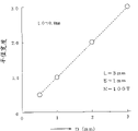
In addition, another magnetic defect detecting device according to the present invention uses pole pitch to be D, the magnet pole widths E shape Magnetic Sensor as E, and it satisfies following formula:
In 1<(D+E)/L<4 formulas, L is the first motion of E shape iron core.
In addition, another magnetic defect detecting device according to the present invention uses the E shape Magnetic Sensor of sensor width as W, and it satisfies following formula:
1<W/L。
In addition, in another magnetic defect detecting device according to the present invention, be configured to make the clearance G s between E shape iron core and magnetic shield panel to satisfy following formula E shape iron core and magnetic shield panel:
In S/10<Gs formula, S is the thickness of barricade.
In addition, in another magnetic defect detecting device according to the present invention, with the interval of spacing P1, embark on journey and arrange E shape Magnetic Sensor, the output of adjacent E shape Magnetic Sensor is used for defects detection mutually on the Width of main body to be detected, wherein, P1 satisfies:
In P1<1.6W formula, W is the width of each E shape Magnetic Sensor.
In another magnetic defect detecting device according to the present invention, interval with spacing P2 disposes E shape Magnetic Sensor in a zigzag on the Width of main body, defects detection is carried out in the bigger output of use overlapped E shape Magnetic Sensor on Width, and P2 satisfies:
P2<0.9W wherein, W is the width of each E shape Magnetic Sensor.
Another magnetic defect detecting device according to the present invention comprises that also cutoff frequency is that the Hi-pass filter of F is handled the output signal from E shape Magnetic Sensor, and cutoff frequency F depends on the distance of pole center in the E shape Magnetic Sensor, the first motion and the translational speed of main body.Reduce the ground unrest composition with Hi-pass filter, therefore the S/N of available optimum detects defective.
In another magnetic defect detecting device according to the present invention, main body is the thin steel band that moves; The defect part of main body is the fine impurity of sneaking in this thin steel band.
Another magnetic defect detecting device according to the present invention also comprises the translational speed that receives main body or/and first motion L (mm) also is provided with the cutoff frequency setting apparatus of the optimum cutoff frequency of Hi-pass filter automatically as input value.Automatically change setting in the cutoff frequency setting apparatus to obtain optimum cutoff frequency according to the translational speed of the distance between magnetic pole, main body and first motion, therefore, always can detect defective with optimum S/N.
In another magnetic defect detecting device according to the present invention, cutoff frequency F be set to the frequency F that satisfies following formula ± 20% scope in:
F=V * (3188-675L) * (850+2000/P)/(1.4 * 10
7) wherein, P (mm) is the distance of the pole center of E shape Magnetic Sensor, L (mm) is a first motion, V (mm/s) is the translational speed of main body.
Along being with one, in the following embodiments, the relevant art of above-mentioned inequality and equation is apparent according to inciting somebody to action.
Magnetic defect inspection method according to the present invention comprises the steps: and will main body to be checked magnetize; Test coil with E shape Magnetic Sensor detects the magnetic flux of the rapid magnetization of previous step in the defect part generation of main body.
Another magnetic defect inspection method according to the present invention also comprises the steps: to compensate the signal of responding to according to the translational speed of main body in test coil.
In another magnetic defect inspection method according to the present invention, compensate so that the signal responded in test coil and the translational speed of main body are inversely proportional to.By compensation, the translational speed of tube body is not how, can obtain constant defective output.
In another magnetic defect inspection method according to the present invention, in the magnetization step of main body, main body is magnetized by non-magnetic material.
Brief description of drawings
Fig. 1 is the schematic diagram of magnetic dispersion method that is used for detecting the defective of magnetisable material;
Fig. 2 is the key diagram that is used to illustrate the operation of typical defects detection coil (test coil);
Fig. 3 is the typical figure that is used for illustrating the voltage of responding at test coil when changing the position of test coil with respect to electromagnet;
Fig. 4 A and 4B are the performance plots of the detection sensitivity of test coil when changing the position of test coil with respect to electromagnet;
Fig. 5 is the figure of the structure of expression E shape Magnetic Sensor according to an embodiment of the invention;
Fig. 6 is the typical figure that is used to illustrate the operation of the E shape Magnetic Sensor of Fig. 5 description when changing the position of E shape Magnetic Sensor with respect to electromagnet;
Fig. 7 is the performance plot of the detection sensitivity of the expression E shape Magnetic Sensor that Fig. 5 describes when changing the position of E shape Magnetic Sensor with respect to electromagnet;
Fig. 8 be expression change in the E shape iron core between magnetic pole apart from the time induced voltage the performance plot of half breadth;
Fig. 9 is the structural drawing when carrying out the leakage flux defects detection with E shape Magnetic Sensor shown in Figure 5;
Figure 10 A to Figure 10 C shows the pass through situation of leakage magnetic flux between the magnetic pole of E shape iron core that is produced by defect part according to time sequencing;
Figure 11 A and 11B illustrate by the waveform of the magnetic energy of test coil and the waveform of induced voltage;
Figure 12 shows when the amplitude size of main body to be measured being carried out defects detection and exporting during the manufacturing defect part artificially in steel plate;
Figure 13 is the performance plot of the detection sensitivity of expression Magnetic Sensor with respect to the magnetic pole length of E shape iron core;
Figure 14 is the performance plot of the detection sensitivity of expression Magnetic Sensor with respect to the initial permeability of E shape iron core;
Figure 15 is the performance plot of the detection sensitivity of expression Magnetic Sensor with respect to the pole pitch of E shape iron core;
Figure 16 is the outside drawing that places as the E shape Magnetic Sensor on the steel plate top of main body to be checked;
Figure 17 A is that expression (D+E)/L is to coming about 10 in the autonomous agent steel plate 13
-3(mm
3) the signal of defective and the performance plot of the influence of ground unrest;
The performance plot of S/N when Figure 17 B is expression change (D+E)/L;
Figure 18 is the performance plot of variation of the output voltage of the E shape Magnetic Sensor of expression when (D+E) keeps the ratio E/D of constant and change magnetic pole thickness E and pole pitch D;
Figure 19 A is that expression comes in the autonomous agent steel plate about 10
-3(mm
3) the detection signal of defective and ground unrest with respect to the performance plot of the relation of W/L;
The performance plot of S/N when Figure 19 B is expression change W/L;
Figure 20 is the structure key diagram of magnetic shield panel that is illustrated in the exterior arrangement ferromagnetic material of E shape Magnetic Sensor;
Figure 21 A is illustrated on the Width of E shape Magnetic Sensor with respect to about 10
-3(mm
3) the performance plot of detection sensitivity of defective;
Figure 21 B is expression detection sensitivity and sensor width W and the performance plot of the relation of the ratio W/L of first motion L;
Figure 22 A and 22B are the key diagrams of expression E shape magnetic sensor configuration example;
Figure 23 is the block scheme of the structure of expression magnetic defect detecting device according to an embodiment of the invention;
Figure 24 is the key diagram of the detailed structure of expression magnetizing apparatus;
Figure 25 is the figure of expression according to the waveform of the artificial defect of the defect detecting device detection of the embodiment of Figure 23;
Figure 26 is the figure of the waveform of expression when detecting natural defect;
Figure 27 A is the performance plot of the sensitivity profile on the main body steel plate width direction in the magnetic defect detecting device (sensor array arrangement) that is illustrated in according to the embodiment of Figure 23;
Figure 27 B is the performance plot of the sensitivity profile on the main body steel plate width direction that is illustrated in the magnetic defect detecting device according to the embodiment of Figure 23 (arranging in a zigzag);
The performance plot of the flaw indication when Figure 28 is expression use E shape Magnetic Sensor in the detection signal and the frequency content intensity of ground unrest;
Figure 29 is the performance plot of the expression example that S/N changes when changing the cutoff frequency of Hi-pass filter;
Figure 30 is the performance plot of the optimum cutoff frequency F (Hz) of the expression Hi-pass filter that makes the S/N maximum when the magnetic pole of E shape Magnetic Sensor size is kept constant and change first motion L (mm);
Figure 31 is the performance plot of the optimum cutoff frequency F (Hz) of the expression Hi-pass filter that makes the S/N maximum when first motion L being kept the pole center distance P (mm) of constant and change E shape Magnetic Sensor;
Figure 32 is expression according to the structured flowchart of the magnetic defect detecting device of the embodiment that above-mentioned cutoff frequency is designed to can change according to the defects detection situation;
Figure 33 is the circuit diagram as the integrating amplifier of the amplifier of Figure 23 and Figure 32 description;
Figure 34 is the performance plot of integrating amplifier that expression is described with Figure 33 relation of the translational speed of detection sensitivity characteristic and main body steel plate when to detect bore dia be the boring defective of 0.1 (mm).
The best mode that carries out an invention
Fig. 5 is the structural drawing of expression E shape Magnetic Sensor according to an embodiment of the invention.E shape Magnetic Sensor 50 is made of E shape iron core 51 and p-wire Figure 52 of ferromagnetic material, and the central magnetic pole 51b of E shape iron core 51 goes up the coil 23 of coiling and formed test coil 52.Have only when going up at one of the magnetic pole 51a of consequent pole 51b and opposite side and 51c (below be called " left magnetic pole 51a " and " right magnetic pole 51c ") when applying externally-applied magnetic field H, just between the output terminals A of coil 23 and B, produce corresponding to the intensity of electromagnetic field and the voltage V of variation thereof from below.Attach and say one, should use such as the E shape iron core 51 of the materials that magnetic permeability is big, coercive force is little such as permalloy iron core, blunt iron iron core as ferromagnetic material.In addition, as shown in drawings, three magnetic poles of a row of being made up of left magnetic pole 51a, center pole 51b and right magnetic pole 51c are placed along the direction of motion as the steel plate of main body to be checked.
The E shape Magnetic Sensor that as above disposes like that is designed to: when the described in the above position of external magnetic field H (below) when work in addition any other position, external magnetic field H does not pass central magnetic pole 51b.To illustrate that this on the one hand according to typical figure shown in Figure 6.
Fig. 6 is the typical figure that is used to illustrate the operation of E shape Magnetic Sensor when changing the position of E shape Magnetic Sensor with respect to electromagnet.When having changed the relative position of E shape Magnetic Sensor and electromagnet, the running of E shape Magnetic Sensor is as follows.When (1) the external magnetic field H that produces when the electromagnet 24 left magnetic pole 51a that acts on E shape iron core 51 went up, external magnetic field H passed left magnetic pole 51a, constitutes a magnetic circuit together with electromagnet 24.At this moment, because magnetic field H is not passed consequent pole 51b, so on test coil 52, do not have induced voltage.(2) same, when external magnetic field H acts on right magnetic pole 51c when going up, between the output terminals A of the coil 23 on consequent pole 51b and B, do not produce voltage, because identical with section (1) described mode, external magnetic field H does not pass consequent pole 51b yet.(3) same, when external magnetic field H acts on the E shape iron core 11 from above, external magnetic field H forms magnetic circuit together with electromagnet 24 in the mode identical with (2) with above-mentioned section (1) because external magnetic field H does not pass the center pole 51b of E shape iron core 51, so in test coil 52 induced voltage not.Along being with one, when under (3) state, during the thickness low LCL of the too strong or iron core 51 of externally-applied magnetic field H, consequent pole 51b is passed and connected to magnetic field H, so will respond to certain voltage (voltage is less) in test coil 52.
The detection sensitivity of E shape Magnetic Sensor 50 will be described below.
Fig. 7 is the performance plot of expression detection sensitivity of Magnetic Sensor when changing the position of E shape Magnetic Sensor with respect to electromagnet.This performance plot represents that the thickness E as each magnetic pole 51a, 51b in the E shape iron core 51 and 51c is that the distance D of 1.0 (mm), magnetic pole is that the length L c of 1.0 (mm), each magnetic pole 51a, 51b, 51c is the number of turn of 3.0 (mm), coil 3 detection sensitivity when being 100T.
As known in the figure, when electromagnet moves along the intermediate shaft Xc direction of passing the consequent pole 51b of E shape iron core 51, when electromagnet 24 arrives intermediate shaft Xc, the induced voltage maximum in the test coil 12, therefore, output voltage V presents the pencil characteristic.In addition ,-half breadth W during 6dB is about 0.8 (mm).
When the following describes the distance D that changes between magnetic pole in test coil 11 half breadth of induced voltage.
Fig. 8 be expression change in the E shape iron core between magnetic pole apart from the time induced voltage the performance plot of half breadth.This performance plot represents that the thickness E as each magnetic pole 51a, 51b in the E shape iron core 51,51c is that the length L c of 1.0 (mm), each magnetic pole 51a, 51b, 51c is that the number of turn N of 3.0 (mm), coil is 100T, the pole pitch characteristic when becoming 0.5 (mm), 1.0 (mm), 2.0 (mm), 3.0 (mm).When pole pitch D became big, the half breadth of the voltage of induction increased in test coil 52.At this moment, characteristic is wide characteristic from the pencil characteristic changing.
From top explanation as seen, by set the pole pitch of E shape iron core according to the size of the defective that will detect, just can detect the leakage magnetic flux that defective produces effectively.
Fig. 9 is the structural drawing when carrying out the leakage magnetic flux defects detection with above-mentioned E shape Magnetic Sensor, and Figure 10 A to Figure 10 C illustrates the pass through situation of leakage flux between the magnetic pole of E shape iron core that is produced by defect part according to time sequencing.Configuration Magnetic Sensor 50 relatively disposes corresponding magnetic pole 51a, 51b and 51c with main body steel plate 13 between the relative magnetic pole of magnet 24.
The operation of E shape Magnetic Sensor 50 is described with reference to Fig. 9, Figure 10 A to 10C below.
Magnet 12 has a pair of pole magnetization 12a and 12b.E shape Magnetic Sensor 50 is configured between pole magnetization 12a and the 12b.When with pole magnetization 12a and 12b magnetization main body steel plate 13, because the normal part of the magneto resistive ratio of base material defect part 14 is big, so form a patching of pole at defect part 14.Owing to there is patching of pole, magnetic flux φ d will leak into outside the main body steel plate 13.When defect part 14 arrives the middle body of the left magnetic pole 51a of E shape iron cores 51 and consequent pole 51b, penetrate left magnetic pole 51a from the leakage magnetic flux φ d of defect part 14, pass from middle magnetic pole 51b then, thereby form a magnetic circuit (referring to Figure 10 A).This moment is induction one voltage corresponding to leakage magnetic flux φ d intensity in test coil 52, so produce voltage V between the output terminal of coil 23.When defect part 14 just arrives under the consequent pole 51b of E shape iron core 51 with moving of main body steel plate 13, leakage magnetic flux φ d from defect part 14 does not pass consequent pole 51b and only passes left and right sides magnetic pole 51a and 51c, so there is not induced voltage (referring to Figure 10 B) in this case in test coil.When defect part 14 arrives center section between consequent pole 51b and right magnetic pole 51c with moving of main body steel plate 13, pass consequent pole 51b and from right magnetic pole 51c, pass from the leakage magnetic flux φ d of defect part 14, thus the formation magnetic circuit.In this case, in test coil 52, induce the voltage corresponding to the intensity of leakage magnetic flux φ d in the same manner as described above, so produce voltage V (referring to Figure 10 c) at the output terminal of coil 23.
Figure 11 A and 11B are the figure of the waveform of the waveform of the magnetic flux of expression by test coil 52 and induced voltage.In above-mentioned sequence of operations, the magnetic flux φ with shape shown in Figure 11 A passes test coil 52, induces the voltage with waveform shown in Figure 11 B.By detecting the existence that induced voltage can detect defective 14.
State in the use among the present invention of E shape Magnetic Sensor 50, at the variable flux of main body steel plate adjacent domain, directly pass magnetic pole 51a from the ground unrest of E shape Magnetic Sensor outside etc. and arrive magnetic pole 51c.Correspondingly, to not influence of test coil 52, so can reduce noise.In addition, the magnetic circuit that constitutes by left magnetic pole and consequent pole 51a and 51b and the magnetic circuit of right magnetic pole and consequent pole 51c and 51b formation can be eliminated the changes of magnetic field that the vibration of steel plate and sensor causes, so can avoid changes of magnetic field to sneak among the signal of test coil 52 as noise.
Correspondingly, can detect defective with good S/N, even first motion is not chosen as too for a short time, variable flux also makes Magnetic Sensor output saturated never.In addition, owing to compare with the frequency content of ground unrest, it is higher relatively that the frequency content of flaw indication becomes, can be easily with signal and noise separation, thus improve the effect of eliminating interference noise.In addition, the structure by coiling on the consequent pole 51b of E shape iron core 51 detects the external magnetic field with very sharp pencil characteristic as sensory characteristic, has improved the sensitivity that low-intensity magnetic field detects.
Figure 12 is the figure of the amplitude size exported when detecting in the main body steel plate artificial defect part of making of expression.Figure 12 represents the result that obtains when the boring that with bore dia is 0.3 φ (mm), 0.2 φ (mm), 0.1 φ (mm) is respectively carried out the leakage magnetic flux defects detection as defect part I1, I2 in the main body steel plate 13 of thickness of slab 0.15 (mm), I3 and with 50 pairs of main body steel plates of Magnetic Sensor 13.Can be to be not less than the boring that 10 S/N detects bore dia 0.1 φ (mm).Along being with one, in Figure 12, will approach output amplitude from the output amplitude of the defect part of bore dia 0.3 φ (mm) from the defect part of bore dia 0.2 φ (mm).Yet this is because the defective output valve exceeds the setting range of setting apparatus, exports saturatedly, has kept the linear characteristic with respect to the pore diameter size of defect part 14.
Figure 13 is the performance plot of the detection sensitivity of expression Magnetic Sensor with respect to the magnetic pole length of E shape iron core.Detection sensitivity when this performance plot represents to use the E shape iron core 11 with different magnetic poles length to detect the defect part 14 of the boring of having made bore dia 0.1 φ (mm) in main body steel plate 13 shown in Figure 9 respectively by Magnetic Sensor 50.Is that unit elongate with 0.5 (mm) with the magnetic pole length L c of E shape iron core 51 in the scope of 1.5 to 4.0 (mm).Suitable speech, the distance between two poles of E shape iron core 51 is 1.0 (mm) from D, is 1.0 (mm) on the thickness of each magnetic pole 51a, 51b, 51c, turn number N is 50T.
As shown in figure 13, when magnetic pole length L c increased, the detection sensitivity of the defect part 14 that boring forms was tending towards reducing.Its reason is, because the magnetic pole length L c of E shape iron core 51 increase, thereby the average length of the magnetic circuit that the leakage magnetic flux φ d that causes defect part 14 to produce passes increases, so the magnetic resistance of magnetic circuit increases.Therefore, with magnetic pole length L c contract as far as possible weak point be favourable, but because the coil turn reduction of permission when magnetic pole length L c reduces is determined magnetic pole length L c so should consider the coil mounting technology.In addition, when substituting main body steel plate 13 as material of main part,, determine the magnetic pole length L c of E shape iron core 51 corresponding to the profile of material of main part for detecting defect part 14 with strip material or pipeline.
Figure 14 is the performance plot of the detection sensitivity of expression Magnetic Sensor with respect to the initial permeability of E shape iron core.The detection sensitivity of the Magnetic Sensor 50 when the figure shows the ferromagnetic material that initial permeability μ i is different as E shape iron core 51.The value of the initial permeability μ i of ferromagnetic material is between about 1800 to about 5500.Along saying one, each magnetic pole 51a, 51b of E shape iron core 51, the length L c of 51c are 3.0mm, and the distance D between magnetic pole is 1.0 (mm), and the thickness E of each magnetic pole is 1.0 (mm), and turn number N is 100T.
As shown in figure 14, when the value of the initial permeability μ i of E shape iron core 51 increased, the detection sensitivity of artificial defect part (bore dia is 0.1 φ (mm)) improved.This be because, when initial permeability μ i increases, the minimizing of magnetic resistance in the E shape iron core 51.Especially, shown in Figure 10 A to 10C, the magnetic flux φ d that defect part 14 produces by the air layer on the main body steel plate 13, pass E shape coil 51 and return main body steel plate 13 then, thereby form a magnetic circuit.The magnetic resistance R φ of the E shape coil 51 in this magnetic circuit is represented by formula (2):
Wherein, Lav is the average length of magnetic path of E shape coil 51, and μ i is the initial permeability of E shape coil 51, and S is the area of section of E shape iron core 51.
Correspondingly, because the magnetic resistance R φ of E shape coil 51 is inversely proportional to the initial permeability μ i of E shape iron core 51, so, use when having the member of big initial permeability μ i, can detect leakage magnetic flux φ d effectively in defect part 14 generations.
Figure 15 is the performance plot of the detection sensitivity of expression Magnetic Sensor with respect to the pole pitch of E shape iron core 51.Detection sensitivity when when the figure shows the area of section (on the thickness) of each magnetic pole 51a, 51b of changing in the E shape coil 51,51c artificial defect part 14 being carried out defects detection.
By following formula (2) as can be known, because the magnetic resistance R φ in the E shape iron core 51 reduces, so, obtained the characteristic that the detection sensitivity of artificial defect part 14 is directly proportional with magnetic pole thickness basically.Explanation in passing, when the magnetic pole thickness E increased, the distance (on the moving direction of main body steel plate 13) that the magnetic flux φ d that artificial defect part 14 produces passes E shape iron core 51 increased.
In this case, also be directly proportional with the magnetic pole thickness E of E shape iron core 51 for a long time by the signal of detection from the leakage magnetic flux gained of artificial defect part 14, and when the translational speed of main body steel plate 13 keeps constant, the frequencies go lower of flaw indication.By improving the magnetic pole thickness E of E shape iron core 51, the magnetic resistance R φ of E shape iron core reduces, so the relative detection sensitivity of artificial defect part 14 improves.Yet, because the frequency shifts of flaw indication is to the lower region, during the frequency of the noise voltage that the various noises (localized variation of thickness of slab, mechanically deform etc.) that exist near main body steel plate 13 when the frequency of flaw indication produce, can not burbling noise.Correspondingly, the magnetic pole thickness E of raising E shape iron core 51 is always not useful.
Figure 16 is the outside drawing of E shape Magnetic Sensor 51 that is placed on the top section of main body steel plate 13.In the drawings, the shape symmetry of E shape Magnetic Sensor 50, identical with the by way of example of Fig. 5, the thickness of magnetic pole equates mutually.Making the distance between magnetic pole is D.The thickness of each magnetic pole is that the width of E, E shape iron core 51 is W.In addition, making the distance between main body steel plate 13 and E shape Magnetic Sensor is that first motion is L.
Figure 17 A is that expression (D+E)/L is to passing through to detect about 10 in the main body steel plate 13
-3The performance plot of the signal of defective gained (mm) and ground unrest influence.When (D+E)/L increased, ground unrest slowly increased.Since (D+E)/when L increased, the area of detection of E shape Magnetic Sensor 50 increased, so this phenomenon can be summed up as the trend of easier reception ground unrest.On the other hand, detection signal has signal and reaches fast rise before 4, slow downward trend afterwards at (D+E)/L.By following consideration.Can think when (D+E)/L too hour, because in magnetic circuit that comes the local leakage magnetic flux of the defect part 14 of autonomous agent steel plate 13 to be imported into simultaneously to constitute and the magnetic circuit that constitutes by right magnetic pole and consequent pole 51c and 51b and partly be cancelled by left magnetic pole and consequent pole 51a and 51b, so, the output voltage of the detection signal in the test coil 52 descends, thereby causes detection efficiency to reduce.Otherwise, can think when (D+E)/L is too big that in the time of under the defect part 14 of main body steel plate 13 is just gone to E shape Magnetic Sensor 50, the variation of magnetic flux reduces in the test coil 52.
The performance plot of S/N when Figure 17 B is expression change (D+E)/L.For above-mentioned reasons, shown in Figure 17 B, when changing (D+E)/L, an optimized scope that makes the S/N maximum is arranged.In the practicality, in that to use in about 20% the S/N scope be effective to reducing from its maximal value from its maximal value.Correspondingly, the size of preferred E shape Magnetic Sensor satisfies following formula (3)
1<(D+E)/L<4 (3)
Figure 18 is the performance plot that the output voltage of the E shape Magnetic Sensor 50 of expression when (D+E) keeps the ratio E/D of constant and change magnetic pole thickness E and pole pitch D changes.Obviously, even when E/D changes, output voltage changes also very little.Yet, in practicality, when magnetic pole thickness too hour, exist such as processing difficulties, problem such as magnetic saturation easily take place, simultaneously, too hour also there are problems such as test coil coiling change difficulty in too big and pole pitch when magnetic pole thickness.Correspondingly, general ratio with E and D is taken in the scope of easy processing.
Figure 19 A is expression by detecting in the main body steel plate 13 about 10
-3(mm
3) defective and signal and ground unrest with respect to the performance plot of the relation of W/L.If the width W of E shape Magnetic Sensor is too little, the sectional area of test coil 52 reduces, and detects voltage and reduces, so detection efficiency reduces.When sensor width W becomes big and reaches a certain value, reveal magnetic flux from the part of microdefect part 14 and all from sensor, pass basically, so even improve sensor width W, output voltage also no longer improves.On the contrary, big if sensor width W becomes, the sensing range that is in E shape Magnetic Sensor 51 belows becomes big, so, owing to have the trend that is easy to receive noise, so ground unrest uprises.Correspondingly, shown in Figure 19 B, when changing W/L, there is an optimized scope that makes the S/N maximum.In the practicality, it is effective using in the scope from the maximal value of S/N to the S/N that reduces by 20% value from this maximal value.Correspondingly, provide following formula from Figure 19 B.
1<W/L<10 (4)
In addition, if become big, just there is the danger of iron core (particularly magnetic pole 51a and the 51c) magnetic saturation of E shape Magnetic Sensor with shape that magnetic flux is easy to pass through from the strong variable magnetic field of magnetizing apparatus.For avoiding this phenomenon and eliminating the external magnetic noise, the magnetic shield panel 56 of a ferromagnetic material is set outside E shape Magnetic Sensor 50 shown in Figure 20.For example, this magnetic shield panel 56 is made of ferromagnetic core.
Be to reduce the size of E shape Magnetic Sensor 50, preferably require to reduce as much as possible the distance of 51 of magnetic shield panel 56 and E shape iron cores.Yet if magnetic shield panel 56 and E shape iron core 51 lean on too closely mutually, the variable magnetic field that barricade 56 absorbs will enter E shape iron core 51, thereby bring adverse effect.Therefore, form a magnetic resistance part inevitably at magnetic shield panel 56 and 51 of E shape iron cores, and its magnetic resistance can not be very little.Because the relative permeability of magnetisable material usually in 100 to 1000 scope and the relative permeability of air be 1, so preferably its magnetic resistance decuples the gap of magnetic resistance in the magnetic shielding approximately.Therefore, the clearance G s of 51 of magnetic shield panel 56 and E shape iron cores must be chosen as about 1/10 of the thickness S that is not less than barricade 56.Correspondingly, preferably provide following formula.
S/10<Gs (5)
Figure 21 A is illustrated in detection sensitivity on the Width of E shape Magnetic Sensor 50 with respect to about 10
-3(mm
3) the performance plot of defective.Shown in Figure 21 A, laterally 80% of (Width) sensitivity maxima width is designated as W80, the width of cross sensitivity peaked 40% is designated as W40, so just obtained characteristic, shown in Figure 21 B with respect to the ratio W/L of sensor width W and first motion L.
Figure 22 A and 22B are the key diagrams of the configuration example of expression E shape Magnetic Sensor 50.In order to cover the defects detection on the steel plate width direction shown in Figure 22 A, with E shape Magnetic Sensor 50 arrangement that is in line, the output addition of adjacent E shape Magnetic Sensor 50, at this moment, sensor 50 compensates mutually, so obtained the sensitivity profile of homogeneous in the preset range on the Width of steel plate.If allow sensitivity profile on the Width of main body steel plate 13 to descend up to 20% so that reduce the number of E shape Magnetic Sensor as far as possible fully from practical point of view, so, the sensitivity of an E shape Magnetic Sensor can drop to 40%.Therefore, from the characteristic of Figure 21 B as can be known, the spacing P1 between preferred E shape Magnetic Sensor satisfies following formula:
P1<1.6W (6)
When with the output addition of adjacent E shape Magnetic Sensor 50, just enlarged the scope that E shape Magnetic Sensor covers, but S/N worsens, this be since the noise component addition so that make the noise amplitude rise to 2
1/2Doubly.When needs avoid S/N to reduce, compare the output of two E shape Magnetic Sensors and the greater in the use output signal successively mutually, can carry out or operate.Yet, in this case, because signal do not have addition, so, do not improve in the reduction of the sensitivity of 50 of E shape Magnetic Sensors.Therefore, be necessary to reduce the distance of 50 of E shape Magnetic Sensors so that the scope that sensitivity is reduced narrows down.In this case, for the reduction with sensitivity is suppressed in peaked 20%, from the characteristic of Figure 21 as can be known, the spacing of 50 of E shape Magnetic Sensors is chosen as 0.9W/L.For obtaining this situation, preferably be in a zigzag, so that be shown on the Width overlapped as Figure 22 B with E shape magnetic sensor configuration.Therefore, preferably the spacing P2 of 50 of E shape Magnetic Sensors is chosen as:
P2<0.9W (7)
That is, when allowing to reduce S/N a little, preferably E shape Magnetic Sensor 50 is configured to straight line as array (Figure 22 A), the output addition of adjacent sensors.On the other hand, do not carry out detection, preferably E shape Magnetic Sensor 50 is configured to (Figure 22 B) in a zigzag, and the output of sensor overlapped on Width is carried out or operation in order not reduce S/N as far as possible.
Figure 23 is the block diagram of the structure of expression magnetic defect detecting device according to an embodiment of the invention.Among the figure, label 57 expression magnetizing apparatuss, the non-magnetic roller of 58 expressions, 59 expression amplifiers, 60 expression wave filters, 61 expression rectifiers, 62 expression decision circuitry.The magnetizing apparatus 57 that will have electromagnet is assemblied in the non-magnetic roller 58, so the main body steel plate (sheet steel) 13 that rolls on non-magnetic roller 58 is magnetized on its rotating direction by non-magnetic roller 58.Above-mentioned E shape Magnetic Sensor 50 is assemblied in above the non-magnetic roller.When minute impurities being arranged, produce faint leakage magnetic flux partly from that when 13 rollings of main body steel plate and in main body steel plate 13 inside.When this magnetic leakage flux passes through under E shape Magnetic Sensor 50 just, as the above, E shape Magnetic Sensor 50 outputs one electric signal corresponding to leakage magnetic flux.It is big to carry out tele-release with the output of 59 pairs of E shapes of amplifier Magnetic Sensor 50, suppresses noise to improve S/N with wave filter 60.After with rectifier 61 rectified current signals, judge defective by decision circuitry, the output judged result.
In this embodiment, respectively first motion L and pole pitch D, magnetic pole thickness E and the sensor width W in the E shape Magnetic Sensor 50 of 50 of main body steel plate 13 and E shape Magnetic Sensors is chosen as L=0.5 (mm), D=0.5 (mm), E=0.4 (mm), W=3.5 (mm).In addition, provide the magnetic shield panel 56 of the permalloy of thickness S=2 (mm), and make formation clearance G s=0.5 (mm) between magnetic shield panel 56 and sensor in the outside of E shape Magnetic Sensor 50.On the Width of steel plate, be in line 220 E shape Magnetic Sensors 50 of configuration as sensor head, so that on the whole width 1100 (mm) of main body steel plate, carry out defects detection, the spacing P1 of 50 of adjacent E shape Magnetic Sensors is chosen as 5 (mm), and the output addition of adjacent E shape Magnetic Sensor is used for detecting.That is, the distance of 52 of E shape Magnetic Sensors is 3.5 (mm).
After amplifier 59, addition is carried out in the output of E shape Magnetic Sensor 50.Also can behind wave filter 60, carry out addition, but carry out before being preferably in rectifier 61.This is because though the signal composition all is easy to addition in rectifier 61 front and back, noise component increases to 2 during addition before rectifier
1/2Doubly, increase to 2 times when carrying out rectifier 61 after, both compare the latter's S/N reduction.With the material of stainless steel, elect the magnetic force of the magnetizing apparatus 57 in the non-magnetic roller 58 as 3000AT as non-magnetic roller 58.The translational speed of main body steel plate (sheet steel) is 300 (m/min).In addition, use cutoff frequency as the Hi-pass filter of 3kHz as wave filter 60.
Figure 24 is the key diagram of the concrete structure of expression magnetizing apparatus 57.As shown in the figure, magnetizing apparatus 57 has a pair of pole magnetization 63a, 63b and a coil 64.Magnetizing apparatus 57 is fixed on the bearing 65.Non magnetic roller is fixed on the bearing 65, and can rotate.By for coil 64 provides direct current, produce magnetic flux from pole magnetization 63a and 63b, so the main body steel plate 13 that rolls on the non-magnetic roller 58 is magnetized on rotating direction by this magnetic flux.
Figure 25 is the figure that the waveform (from the output waveform of rectifier 11) of the artificial defect that detects according to the defect detecting device of the foregoing description is used in expression.The figure shows the output waveform when detecting artificial defect in sheet steel, this artificial defect is that bore dia is respectively the machine drilling of 0.5,0.1,0.2 (mm).As can be seen from Figure 25, available high S/N detects microdefect.
Oscillogram when in addition, Figure 26 is expression detection natural flaw.After defects detection, downcut defect part, after the defect part polishing, with its size of microexamination.The result has size about 5 * 10
-4(mm
3) impurity.
The best cutoff frequency of wave filter 60 is 3kHz.The twice of optimal value or three times when this value is to use conventional Magnetic Sensor.The ground unrest that correspondingly comprises a large amount of low-frequency components can easily be separated with detection signal, so improved S/N significantly.Behind the magnetic shield panel of removing the outside that is configured in E shape iron core 51, E shape Magnetic Sensor 50 magnetic saturations, the sensitivity of sensor reduces.Therefore, use magnetic force to be reduced to the E shape Magnetic Sensor 50 of 2000AT, but can not detect the artificial defect that bore dia is the boring of 0.05 (mm) this moment in order to avoid make E shape Magnetic Sensor 50 saturated.
Figure 27 A is the performance plot that is illustrated in according to the sensitivity profile on the Width of the main body steel plate in the magnetic defect detecting device of this embodiment.Transverse axis is illustrated in the distance Y (mm) on the Width, and Z-axis is represented the relative value of sensitivity.Because the spacing of E shape sensor is configured to 5 (mm), so 5 (mm) locate the sensitivity maximum at the interval, sensitivity minimum in the time of in the middle of E shape Magnetic Sensor 50, but the reduction of sensitivity is suppressed within 20%.
In addition, substitute as the sensor head, two sensor arraies are configured in a zigzag, this sensor groups is carried out magnetic shielding as a whole, wherein, each sensor array is by being that 183 E shape Magnetic Sensors of 2.5 (mm) are in line to arrange and form with pole pitch D=0.5 (mm), magnetic pole thickness D=0.4 (mm), sensor width W=3.5 (mm), sensor distance.At this moment, the overlapping width of sensor is 0.5 (mm).In addition, in the zigzag of sensor is arranged, used the signal that the output of overlapping sensor is carried out or operated gained.At this moment, Figure 27 B shows the sensitivity profile on the Width of steel plate, will reduce with respect to the sensitivity of peak response to be suppressed to about 20%.
Though the cross sectional shape of each magnetic pole is square in the E shape Magnetic Sensor 50 shown in the present embodiment, it also is identical by chamfering cross sectional shape being become the bowlder effect.
Below separating background noise and defect detection signal will be discussed.
Figure 28 is expression performance plot of the intensity of the radio-frequency component of the intensity of the radio-frequency component of flaw indication and ground unrest in the detection signal when using E shape Magnetic Sensor.Ground unrest comprises a large amount of low frequency compositions, and flaw indication has a spike at a certain frequency place.Therefore, obviously, can improve S/N when removing the low frequency composition with Hi-pass filter 60.
Figure 29 is the performance plot of the expression example that S/N changes when changing the cutoff frequency of Hi-pass filter 60.According to this characteristic, there is the best cutoff frequency make the S/N maximum, when cutoff frequency left best cutoff frequency+20%, S/N reduced 20%.Correspondingly, if allow S/N to reduce 20%, so just can use the efficient of ending in best cutoff frequency+20% scope with respect to the maximal value of S/N.
Figure 30 is the performance plot of the best cutoff frequency F (Hz) of the expression Hi-pass filter 60 that makes the S/N maximum when the magnetic pole of E shape Magnetic Sensor 50 size is kept constant and change first motion L (mm).When respectively the spacing P of the translational speed V of main body steel plate 13 and the pole center in the E shape Magnetic Sensor 50 being made as V=5000 (mm/s) and P=1 (mm), obtain F=3188-657L.
Figure 31 is the performance plot of the best cutoff frequency F (Hz) of the expression Hi-pass filter 60 that makes the S/N maximum when first motion L being kept the pole center spacing P (mm) of constant and change E shape Magnetic Sensor.When respectively the first motion L of main body steel plate 13 and translational speed being made as L=0.5 (mm) and V=5000 (mm/s), obtain F=(850+2000/P).Can think that the best cutoff frequency of the Hi-pass filter that makes the S/N maximum is directly proportional with the translational speed of main body steel plate.
It is as follows to provide best cutoff frequency F from these results.
F=V×(3188-675L)×(850+2000/P)/(1.4×10
7)
(8)
Also can think with respect to the permissible value of the optimum value of cutoff frequency F above-mentioned value ± 20% scope in.
The block diagram of the structure of the magnetic defect detecting device of Figure 32 embodiment that to be expression can change with the defects detection situation according to above-mentioned cutoff frequency F.Construct this magnetic defect detecting device by on the defect detecting device of Figure 23, adding automatic cut-off frequency setter 70.
Automatic cut-off frequency setter 70 reads the spacing P of the pole center of E shape Magnetic Sensor 50, the first motion L and the translational speed V of main body steel plate 13, carries out the calculating of following formula (8), obtains cutoff frequency, and the cutoff frequency of gained is set for Hi-pass filter 60.When microcomputer is used as automatic cut-off frequency setter 70, can easily realize the calculating of formula (8).When the spacing P with the pole center in the E shape Magnetic Sensor 50 regards fixed value as or first motion L and spacing P is considered as fixed value, can in automatic cut-off frequency setter 13, set fixed value in advance, be worth so just need not import these from the outside.
Explanation in passing, at this moment, E shape sensor 50 preferably is enclosed in the magnetic shield panel 56 of ferromagnetic material, so that reduce the influence in the magnetic field of floating.
In the magnetic defect detecting device of structure shown in Figure 32, first motion L, the magnet pole widths D of E shape Magnetic Sensor 50, the magnetic pole thickness E with 50 of main body steel plate 13 and E shape Magnetic Sensors is set at L=0.5 (mm), D=0.5 (mm), E=0.4 (mm), W=3.5 (mm) respectively.In addition, provide the permalloy magnetic shield panel 56 of thickness S=2 (mm) in the outside of E shape Magnetic Sensor 1, the clearance G s=0.5 (mm) that between magnetic shield panel 56 and E shape Magnetic Sensor 50, forms.As the material of non magnetic roller 58, and the magnetic force of the magnetizing apparatus 57 in the non magnetic roller 58 elected stainless steel as 3000AT.The translational speed V of main body steel plate (sheet steel) elects V=5000 (mm/s) as.
In addition, with L, V, P input automatic cut-off frequency setter 13, carry out arithmetical operation according to formula (8), arithmetic operation results is imported Hi-pass filter 60, and the cutoff frequency with Hi-pass filter is set at optimum value automatically, even if operating conditions also is like this when changing.Explanation in passing, under above-mentioned condition, the cutoff frequency F=3000 (Hz) of Hi-pass filter.
Figure 33 is the circuit block diagram as the integrating amplifier of the amplifier 59 of Figure 23 and Figure 32 description.This integrating amplifier 71 comprises integrating resistor R4, capacitor C 1 and amplifier 72.When the flaw indication that detects when the test coil 52 of E shape Magnetic Sensor 50 is exaggerated, the output voltage e that obtains in the test coil 52
0Provide by following formula.
That is output voltage e,
0Become the absolute value of the magnetic flux d that produces with defective and make defective 14 just in time from test coil 52 below by the time output that the required time is inversely proportional to.Therefore, by with the amplifier of integrating amplifier as the output of amplifying test coil 52, the compensation output valve of same defective of increase that is directly proportional with the translational speed of main body steel plate 13 automatically, so, the translational speed of tube body steel plate is not how, all can obtain constant amplifier defective output.
Figure 34 is expression with the integrating amplifier of Figure 33 is the boring defective of 0.1 (mm) when carrying out defects detection, the detection sensitivity characteristic performance plot with respect to the relation of the translational speed of ferromagnetic metal plate to bore dia.As shown in the figure, even if when 10 change the translational speed of main body steel plate 13 in the scope of 1000m/min, the sensitivity difference that detects boring also is suppressed in 5% the scope.