CN116413940A - An image depth modulation module, display module and near-eye display device - Google Patents
An image depth modulation module, display module and near-eye display device Download PDFInfo
- Publication number
- CN116413940A CN116413940A CN202211720104.0A CN202211720104A CN116413940A CN 116413940 A CN116413940 A CN 116413940A CN 202211720104 A CN202211720104 A CN 202211720104A CN 116413940 A CN116413940 A CN 116413940A
- Authority
- CN
- China
- Prior art keywords
- electronically controlled
- controlled dimming
- image
- layer
- modulation module
- Prior art date
- Legal status (The legal status is an assumption and is not a legal conclusion. Google has not performed a legal analysis and makes no representation as to the accuracy of the status listed.)
- Pending
Links
Images


Classifications
-
- G—PHYSICS
- G02—OPTICS
- G02F—OPTICAL DEVICES OR ARRANGEMENTS FOR THE CONTROL OF LIGHT BY MODIFICATION OF THE OPTICAL PROPERTIES OF THE MEDIA OF THE ELEMENTS INVOLVED THEREIN; NON-LINEAR OPTICS; FREQUENCY-CHANGING OF LIGHT; OPTICAL LOGIC ELEMENTS; OPTICAL ANALOGUE/DIGITAL CONVERTERS
- G02F1/00—Devices or arrangements for the control of the intensity, colour, phase, polarisation or direction of light arriving from an independent light source, e.g. switching, gating or modulating; Non-linear optics
- G02F1/01—Devices or arrangements for the control of the intensity, colour, phase, polarisation or direction of light arriving from an independent light source, e.g. switching, gating or modulating; Non-linear optics for the control of the intensity, phase, polarisation or colour
- G02F1/13—Devices or arrangements for the control of the intensity, colour, phase, polarisation or direction of light arriving from an independent light source, e.g. switching, gating or modulating; Non-linear optics for the control of the intensity, phase, polarisation or colour based on liquid crystals, e.g. single liquid crystal display cells
- G02F1/133—Constructional arrangements; Operation of liquid crystal cells; Circuit arrangements
- G02F1/1333—Constructional arrangements; Manufacturing methods
- G02F1/1334—Constructional arrangements; Manufacturing methods based on polymer dispersed liquid crystals, e.g. microencapsulated liquid crystals
-
- G—PHYSICS
- G02—OPTICS
- G02B—OPTICAL ELEMENTS, SYSTEMS OR APPARATUS
- G02B27/00—Optical systems or apparatus not provided for by any of the groups G02B1/00 - G02B26/00, G02B30/00
- G02B27/01—Head-up displays
- G02B27/017—Head mounted
- G02B27/0172—Head mounted characterised by optical features
-
- Y—GENERAL TAGGING OF NEW TECHNOLOGICAL DEVELOPMENTS; GENERAL TAGGING OF CROSS-SECTIONAL TECHNOLOGIES SPANNING OVER SEVERAL SECTIONS OF THE IPC; TECHNICAL SUBJECTS COVERED BY FORMER USPC CROSS-REFERENCE ART COLLECTIONS [XRACs] AND DIGESTS
- Y02—TECHNOLOGIES OR APPLICATIONS FOR MITIGATION OR ADAPTATION AGAINST CLIMATE CHANGE
- Y02B—CLIMATE CHANGE MITIGATION TECHNOLOGIES RELATED TO BUILDINGS, e.g. HOUSING, HOUSE APPLIANCES OR RELATED END-USER APPLICATIONS
- Y02B20/00—Energy efficient lighting technologies, e.g. halogen lamps or gas discharge lamps
- Y02B20/40—Control techniques providing energy savings, e.g. smart controller or presence detection
Landscapes
- Physics & Mathematics (AREA)
- Chemical & Material Sciences (AREA)
- Nonlinear Science (AREA)
- General Physics & Mathematics (AREA)
- Optics & Photonics (AREA)
- Dispersion Chemistry (AREA)
- Mathematical Physics (AREA)
- Crystallography & Structural Chemistry (AREA)
- Liquid Crystal (AREA)
Abstract
本发明公开了一种图像深度调制模组,包括堆叠设置的多层电控调光板,每层电控调光板由若干电控调光单元组成,每个电控调光单元具有独立开关,不同电控调光板上的任一电控调光单元可独立被调控为透射状态或散射状态;在所述图像深度调制模组工作时,各层所述电控调光板中的电控调光单元协同被调控为透射状态或散射状态。同时,本发明还公开了应用该图像深度调制模组的显示模组和近眼显示设备,通过物理结构给图像加载景深,实现像素级或准像素级景深调节,可以解决视觉辐辏冲突效应、使人眼观察到的图像更符合人眼的聚焦习惯、使显示图像的深度排布更接近现实光场的深度规律。

The invention discloses an image depth modulation module, which comprises stacked multi-layer electronically controlled dimming boards, each layer of electronically controlled dimming boards is composed of several electronically controlled dimming units, and each electronically controlled dimming unit has an independent switch , any electronically controlled dimming unit on different electronically controlled dimming boards can be independently adjusted to a transmission state or a scattering state; when the image depth modulation module is working, the electrical The light control and adjustment units are coordinated to be adjusted to be in a transmission state or a scattering state. At the same time, the present invention also discloses a display module and a near-eye display device using the image depth modulation module, which loads the depth of field to the image through the physical structure, and realizes pixel-level or quasi-pixel-level depth of field adjustment, which can solve the visual convergence conflict effect and make people The image observed by the human eye is more in line with the focusing habits of the human eye, making the depth arrangement of the displayed image closer to the depth law of the real light field.
Description
技术领域technical field
本发明涉及图像显示领域,尤其涉及一种图像深度调制模组、应用该图像深度调制模组的显示模组和近眼显示设备。The invention relates to the field of image display, in particular to an image depth modulation module, a display module and a near-eye display device using the image depth modulation module.
背景技术Background technique
现有的HMD(HeadMountDisplay,头戴式可视设备)虚拟现实/增强现实的显示系统,大部分光学显示系统是按照一固定成像距离设计,因此图像源经光学显示系统后在人眼前方显示的虚像距人眼的距离是固定的,这种不带图像景深的显示,会造成视觉辐辏调节冲突(Vergence-Accommodation Conflict,VAC)导致“晕动症”,用户体验极差。且如果将这样的HMD设备用于增强现实应用,由于虚像距人眼的距离是不变的,而所处环境是时刻改变的,通过这些显示系统看到的虚像就是飘浮在空中的,与实际环境脱离,不能达到真正的增强显示效果。In the existing HMD (Head Mount Display, head-mounted visual device) virtual reality/augmented reality display system, most of the optical display systems are designed according to a fixed imaging distance, so the image source is displayed in front of the human eye after passing through the optical display system The distance between the virtual image and the human eye is fixed. This kind of display without image depth of field will cause Vergence-Accommodation Conflict (VAC), resulting in "motion sickness", and the user experience is extremely poor. And if such an HMD device is used for augmented reality applications, since the distance between the virtual image and the human eye is constant, and the environment is constantly changing, the virtual image seen through these display systems is floating in the air, which is different from the actual The environment is separated, and the real enhanced display effect cannot be achieved.
发明内容Contents of the invention
本发明的目的是提供一种图像深度调制模组、应用该图像深度调制模组的显示模组和近眼显示设备,实现具有景深的图像显示,同时解决近眼显示设备视觉辐辏冲突问题。The purpose of the present invention is to provide an image depth modulation module, a display module using the image depth modulation module, and a near-eye display device, so as to realize image display with depth of field and solve the problem of visual convergence conflict of the near-eye display device.
为了实现上述发明目的,本发明提供了一种图像深度调制模组,包括堆叠设置的多层电控调光板,每层电控调光板由若干电控调光单元组成,每个电控调光单元具有独立开关,不同电控调光板上的任一电控调光单元可独立被调控为透射状态或散射状态;In order to achieve the purpose of the above invention, the present invention provides an image depth modulation module, including stacked multi-layer electronically controlled dimming boards, each layer of electronically controlled dimming boards is composed of several electronically controlled dimming units, each electronically controlled The dimming unit has an independent switch, and any electronically controlled dimming unit on different electronically controlled dimming boards can be independently adjusted to a transmission state or a scattering state;
在所述图像深度调制模组工作时,各层所述电控调光板中的电控调光单元协同被调控为透射状态或散射状态。When the image depth modulation module is working, the electronically controlled dimming units in the electronically controlled dimming panels of each layer are cooperatively adjusted to be in a transmission state or a scattering state.
优选的,所述电控调光单元为聚合物稳定液晶光电单元或聚合物分散液晶光电单元。Preferably, the electronically controlled dimming unit is a polymer stabilized liquid crystal photoelectric unit or a polymer dispersed liquid crystal photoelectric unit.
优选的,多层电控调光板平行间隔设置。Preferably, the multi-layer electronically controlled dimming boards are arranged in parallel and at intervals.
相应的,本发明还提供了一种显示模组,包括图像产生模组、图像深度调制模组和物镜系统,图像深度调制模组为上述的图像深度调制模组,图像产生模组产生的图像光先经图像深度调制模组,再经物镜系统出射。Correspondingly, the present invention also provides a display module, including an image generation module, an image depth modulation module and an objective lens system, the image depth modulation module is the above-mentioned image depth modulation module, and the image generated by the image generation module The light first passes through the image depth modulation module, and then exits through the objective lens system.
优选的,所述的每层电控调光板上的每个电控调光单元对应图像产生模组产生的一个或多个像素点。Preferably, each electronically controlled dimming unit on each layer of the electrically controlled dimming board corresponds to one or more pixels generated by the image generation module.
优选的,所述图像深度调制模组包括堆叠设置的12层电控调光板。Preferably, the image depth modulation module includes 12 layers of electronically controlled dimming boards stacked.
优选的,每层电控调光板的成像距离Pn按如下公式设计:Preferably, the imaging distance P n of each layer of electronically controlled dimming panels is designed according to the following formula:

其中,L为人眼瞳孔直径,ε表示人眼分辨率,n为电控调光板的层数,n为1时,代表离物镜系统最近的第一层电控调光板。Among them, L is the pupil diameter of the human eye, ε represents the resolution of the human eye, n is the number of layers of the electronically controlled dimming board, and when n is 1, it represents the first layer of the electronically controlled dimming board closest to the objective lens system.
优选的,ε范围为1’到3’,L范围为2mm-5mm。Preferably, the range of ε is 1' to 3', and the range of L is 2mm-5mm.
优选的,ε为2’,L为3.5mm。Preferably, ε is 2', and L is 3.5mm.
优选的,每个所述电控调光单元的散射角小于60°且大于5°。Preferably, the scattering angle of each electronically controlled dimming unit is less than 60° and greater than 5°.
相应的,本发明还提供了一种近眼显示设备,包括一组或两组近眼显示光学系统,每组近眼显示光学系统包括一组如上述的显示模组和导光系统,图像产生模组产生的图像光先经图像深度调制模组,再经物镜系统入射至导光系统,由导光系统出射至人眼。Correspondingly, the present invention also provides a near-eye display device, including one or two groups of near-eye display optical systems, each group of near-eye display optical systems includes a set of display modules and light guide systems as described above, and the image generation module generates The image light first passes through the image depth modulation module, and then enters the light guide system through the objective lens system, and then exits from the light guide system to the human eye.
优选的,近眼显示设备还包括处理器,处理器控制图像产生模组产生图像光的同时,控制图像深度调制模组根据图像光不同区域对应的不同景深,控制每层电控调光板中每个电控调光单元调整为透射状态或散射状态。Preferably, the near-eye display device further includes a processor, and the processor controls the image generation module to generate image light, and at the same time controls the image depth modulation module to control each layer of the electronically controlled dimming board according to the different depths of field corresponding to different regions of the image light. An electronically controlled dimming unit is adjusted to the transmission state or the scattering state.
其中,控制图像深度调制模组根据图像光不同区域对应的不同景深,控制每层电控调光板中每个电控调光单元调整为透射状态或散射状态,具体为:Among them, the control image depth modulation module controls each electronically controlled dimming unit in each layer of electronically controlled dimming boards to adjust to a transmission state or a scattering state according to different depths of field corresponding to different areas of the image light, specifically:
控制某区域图像光对应景深所对应的电控调光板的对应区域的电控调光单元调整为散射状态,堆叠设置的其他层电控调光板的对应区域的电控调光单元调整为透射状态。Control the electronically controlled dimming unit in the corresponding area of the electronically controlled dimming board corresponding to the depth of field corresponding to the image light in a certain area to adjust to the scattering state, and adjust the electronically controlled dimming unit in the corresponding area of the electronically controlled dimming board on other layers arranged in a stack to transmission state.
与现有技术相比,本发明具有如下有益效果:Compared with the prior art, the present invention has the following beneficial effects:
本发明实施例方案通过物理结构给图像加载景深,实现像素级或准像素级景深调节,可以解决视觉辐辏冲突效应、使人眼观察到的图像更符合人眼的聚焦习惯、使显示图像的深度排布更接近现实光场的深度规律。The embodiment scheme of the present invention loads the depth of field to the image through the physical structure, realizes pixel-level or quasi-pixel-level depth-of-field adjustment, can solve the visual convergence conflict effect, make the image observed by the human eye more in line with the focusing habit of the human eye, and make the depth of the displayed image The arrangement is closer to the depth law of the real light field.
附图说明Description of drawings
为了更清楚地说明本发明实施例或现有技术中的技术方案,下面将对实施例或现有技术描述中所需要使用的附图作简单地介绍,显而易见地,下面描述中的附图仅仅是本发明的一些实施例,对于本领域普通技术人员来讲,在不付出创造性劳动性的前提下,还可以根据这些附图获得其他的附图:In order to more clearly illustrate the technical solutions in the embodiments of the present invention or the prior art, the following will briefly introduce the drawings that need to be used in the description of the embodiments or the prior art. Obviously, the accompanying drawings in the following description are only These are some embodiments of the present invention. For those of ordinary skill in the art, other drawings can also be obtained according to these drawings on the premise of not paying creative labor:
图1为本发明实施例图像深度调制模组结构示意图;FIG. 1 is a schematic structural diagram of an image depth modulation module according to an embodiment of the present invention;
图2为图1中每层电控调光板的结构示意图;Fig. 2 is a schematic structural diagram of each layer of electronically controlled dimming panels in Fig. 1;
图3为本发明实施例显示模组的一种结构示意图;FIG. 3 is a schematic structural diagram of a display module according to an embodiment of the present invention;
图4为本发明实施例显示模组的另一种结构示意图;FIG. 4 is another structural schematic diagram of a display module according to an embodiment of the present invention;
图5为本发明实施例图像产生模组产生一幅风景图像示意图;Fig. 5 is a schematic diagram of a landscape image generated by the image generation module of the embodiment of the present invention;
图6为本发明实施例近眼显示设备中近眼显示光学系统的一种结构示意图;6 is a schematic structural diagram of a near-eye display optical system in a near-eye display device according to an embodiment of the present invention;
图7为本发明实施例近眼显示设备的一种结构示意图。FIG. 7 is a schematic structural diagram of a near-eye display device according to an embodiment of the present invention.
具体实施方式Detailed ways
下面将结合本发明实施例中的附图,对本发明实施例中的技术方案进行清楚、完整地描述,显然,所描述的实施例仅仅是本发明一部分实施例,而不是全部的实施例。基于本发明中的实施例,本领域普通技术人员在没有作出创造性劳动前提下所获得的所有其他实施例,都属于本发明保护的范围。The following will clearly and completely describe the technical solutions in the embodiments of the present invention with reference to the accompanying drawings in the embodiments of the present invention. Obviously, the described embodiments are only some, not all, embodiments of the present invention. Based on the embodiments of the present invention, all other embodiments obtained by persons of ordinary skill in the art without creative efforts fall within the protection scope of the present invention.
参见图1,为本发明实施例图像深度调制模组结构示意图,本发明实施例图像深度调制模组包括堆叠设置的多层电控调光板10,每层电控调光板10由若干电控调光单元101组成,每层电控调光板10的结构示意图参见图2,每个电控调光单元101具有独立开关,开关可以采用透明或半透明半导体开关,每个电控调光单元可被调控为透射状态或散射状态。Referring to Fig. 1 , it is a schematic diagram of the structure of the image depth modulation module according to the embodiment of the present invention. The image depth modulation module according to the embodiment of the present invention includes stacked multi-layer electronically controlled
一幅影像从图像深度调制模组的一侧入射,影像的第一部分通过一层电控调光板10的第一区域,由于电控调光板上每个电控调光单元都可独立调控,所以此时能够控制第一区域中的电控调光单元变为散射状态,则影像的第一部分在该电控调光板的第一区域被散射,此时影像的第一部分被加载一个深度信息;影像的第二部分通过另一个电控调光板上的第二区域并被散射,此时影像的第二部分被加载另一个深度信息;以此类推,每个电控调光板可负责一个深度,最终实现能够将多个深度信息加载在影像上。当组成电控调光板10的每个电控调光单元101的大小做到到足够小,则可以实现像素或者准像素级别的深度调制。An image is incident from one side of the image depth modulation module, and the first part of the image passes through the first area of a layer of electronically controlled
优选的,所述电控调光单元可以选择采用聚合物稳定液晶光电单元PSLC(polymerstabilized liquid crystal)或反向PSLC,也可以选择采用聚合物分散液晶光电单元PDLC(polymer dispersed liquid crystal)等具备同样物理特性的光电单元,所述电控调光单元通过施加电压或不施加电压切换状态为透射状态或散射状态。以电控调光单元为PSLC为例:控制PSLC的电极可选用TFT(Thin Film Transistor)或ITO等类似的技术,做成类似于TFT式显示屏,只不过TFT中的每个液晶像素点替换成像素级大小的PSLC,这样每个PSLC便能够被对应位置的半导体开关控制,一般采用电脉冲控制;每个PSLC便可分别独立地由各自对应位置的半导体开关进行独立控制。例如,一个PSLC电控调光板的参数可以设计为尺寸3*4.5mm,分辨率640*540,厚度10um~30um,组成PSLC电控调光板的每个PSLC的大小做到足够小,例如一个PSLC的大小做到边长为10μm的正方形,这样入射的影像的两个不同深度对应的部分能够互相配合得更平滑。Preferably, the electronically controlled dimming unit can choose to use a polymer stabilized liquid crystal photoelectric unit PSLC (polymerstabilized liquid crystal) or reverse PSLC, and can also choose to use a polymer dispersed liquid crystal photoelectric unit PDLC (polymer dispersed liquid crystal). A photoelectric unit with physical characteristics, the electronically controlled dimming unit is switched to a transmission state or a scattering state by applying a voltage or not applying a voltage. Take PSLC as an example for the electronically controlled dimming unit: TFT (Thin Film Transistor) or ITO and other similar technologies can be used to control the electrodes of PSLC, which is similar to a TFT display, except that each liquid crystal pixel in the TFT is replaced The PSLC is formed into a pixel-level PSLC, so that each PSLC can be controlled by a semiconductor switch at a corresponding position, generally using electric pulse control; each PSLC can be independently controlled by a semiconductor switch at its corresponding position. For example, the parameters of a PSLC electronically controlled dimming board can be designed to have a size of 3*4.5mm, a resolution of 640*540, and a thickness of 10um to 30um. The size of a PSLC is a square with a side length of 10 μm, so that the parts corresponding to the two different depths of the incident image can match each other more smoothly.
为了使整个图像画面深度调制匀称,优选多层电控调光板平行间隔设置,至于相邻电控调光板之间的间隔距离,需根据预设调焦距离的不同,是否配合其他放大光学元件使用等方式不同,可设计为不同间距,在此不做限定。In order to make the depth modulation of the entire image picture uniform, it is preferable to arrange multi-layer electronically controlled dimming boards in parallel and at intervals. As for the distance between adjacent electronically controlled dimming boards, it needs to be used according to the difference in the preset focusing distance and whether it cooperates with other magnifying optics. Depending on the use of components, etc., different pitches can be designed, which is not limited here.
参见图3,为本发明实施例显示模组结构示意图,本发明实施例近眼显示光学模组包括图像产生模组2、图像深度调制模组1和物镜系统3,图像深度调制模组1为前述实施例所述的图像深度调制模组,图像产生模组2产生准直图像光,先经图像深度调制模组1加载深度信息后,再经物镜系统3出射。在本发明实施例中,所述的每层电控调光板上的每个电控调光单元可以设计为对应图像产生模组产生的一个或多个像素点,当每个电控调光单元设计为对应图像产生模组产生的一个像素点时,即实现了像素级深度调制。Referring to FIG. 3 , it is a schematic structural diagram of a display module according to an embodiment of the present invention. The near-eye display optical module according to an embodiment of the present invention includes an
图3中图像深度调制模组1为前向散射,在具体实施时,也可以采用图4方式,将图像产生模组2放置在图像深度调制模组1的另一侧,通过后向散射方式实现。In Fig. 3, the image
本发明实施例方案通过物理结构给图像加载景深,可以解决视觉辐辏冲突效应、使人眼观察到的图像更符合人眼的聚焦习惯、使显示图像的深度排布更接近现实光场的深度规律。由于人眼一般只对12层深度敏感,因此12层电控调光板构成图像深度调制模组最佳,当然如果为了减小近眼显示光学模组的体积和重量,则可以选用3、4、5或6、7、8层等,同样具备景深效果,只是效果无法达到12层的自然。The embodiment scheme of the present invention loads the depth of field to the image through the physical structure, which can solve the visual convergence conflict effect, make the image observed by the human eye more in line with the focusing habit of the human eye, and make the depth arrangement of the displayed image closer to the depth law of the real light field . Since the human eye is generally only sensitive to the depth of 12 layers, the 12-layer electronically controlled dimming board constitutes the best image depth modulation module. Of course, if you want to reduce the volume and weight of the near-eye display optical module, you can choose 3, 4, 5 or 6, 7, 8 layers, etc., also have the effect of depth of field, but the effect cannot reach the naturalness of 12 layers.
下面结合图5描述本发明显示模组如何实现景深,假设电控调光单元为PSLC,如图5,为图像产生模组产生一幅风景图像,该风景图像从图像深度调制模组的一侧入射,树的图像区域和山的图像区域具有不同的深度。例如:树的图像区域由图像深度调制模组的第一层电控调光板负责,第一层电控调光板上被树的图像区域辐照的多个PSLC被控制成散射状态,树的显示位置位于第一层电控调光板的位置,即聚焦位置位于第一层电控调光板的位置,第一层电控调光板上其他区域的PSLC则被控制成透射状态,第一层电控调光板上散射状态PSLC在其他层电控调光板上的投影区域的PSLC则也须被控制为透射状态;山的图像区域由图像深度调制模组的第二层电控调光板负责,第二层电控调光板上被山的图像区域辐照的多个PSLC被控制成散射状态,山的显示位置位于第二层电控调光板的位置,即聚焦位置位于第二层电控调光板的位置,第二层电控调光板上其他区域的PSLC则被控制成透射状态,第二层电控调光板上散射状态PSLC在其他层电控调光板上的投影区域的PSLC则也须被控制为透射状态;以此类推,风景图像的其他深度的图像部分均被显示在某层电控调光板上,即,在同一时间内有多层电控调光板切换为散射状态。由于人眼的聚焦特性,当人眼聚焦在某层电控调光板上时,其他层电控调光板则在人眼中会呈为模糊像,以实现景深的效果。只要每个PSLC的大小足够小,那么第一深度区域~第五深度区域对应的五幅深度图像互相之间便会衔接得更为平滑。The following describes how the display module of the present invention realizes the depth of field in conjunction with Fig. 5, assuming that the electronically controlled dimming unit is a PSLC, as shown in Fig. 5, a landscape image is generated for the image generation module, and the landscape image is modulated from one side of the image depth modulation module Incidence, the tree's image area and the mountain's image area have different depths. For example: the image area of the tree is in charge of the first layer of electronically controlled dimming board of the image depth modulation module, and multiple PSLCs irradiated by the image area of the tree on the first layer of electronically controlled dimming board are controlled into a scattering state, and the tree The display position of the display is located at the position of the first layer of electronically controlled dimming board, that is, the focus position is located at the position of the first layer of electronically controlled dimming board, and the PSLC in other areas on the first layer of electronically controlled dimming board is controlled into a transmissive state The PSLC in the projection area of the PSLC in the scattering state on the first layer of electronically controlled dimming boards on other layers of electronically controlled dimming boards must also be controlled to be in a transmissive state; The control dimming board is responsible. The multiple PSLCs irradiated by the image area of the mountain on the second layer of the electronic control dimming board are controlled into a scattering state. The display position of the mountain is located at the position of the second layer of electronic control dimming board, that is, focusing The position is located at the position of the second layer of electronically controlled dimming board, and the PSLC in other areas on the second layer of electronically controlled dimming board is controlled to be in the transmission state, and the scattering state PSLC on the second layer of electronically controlled dimming board is electrically controlled on other layers. The PSLC of the projection area on the dimming board must also be controlled to be in a transmissive state; by analogy, the image parts of other depths of the landscape image are all displayed on a certain layer of electronically controlled dimming board, that is, at the same time there are The multi-layer electronically controlled dimming board is switched to the scattering state. Due to the focusing characteristics of the human eye, when the human eye focuses on a certain layer of electronically controlled dimmers, other layers of electronically controlled dimmers will appear as blurred images to achieve the effect of depth of field. As long as the size of each PSLC is small enough, the five depth images corresponding to the first depth area to the fifth depth area will be more smoothly connected to each other.
上一段讲述了多层电控调光板怎样实现景深的方法,下面介绍在上一段基础上,怎样设计每层电控调光板的图像聚焦位置来更好地解决视觉辐辏冲突、更好地模拟现实光场。The previous paragraph described how to realize the depth of field of multi-layer electronically controlled dimming boards. The following describes how to design the image focus position of each layer of electronically controlled dimming boards on the basis of the previous paragraph to better solve visual convergence conflicts and better Simulates realistic light fields.
下面我们对人眼的景深进行简单的计算,人眼的分辨率用ε表示,瞳孔直径为L。当人眼调焦距离为P时,其远景P1和近景P2的距离为:Next, we simply calculate the depth of field of the human eye. The resolution of the human eye is represented by ε, and the diameter of the pupil is L. When the focusing distance of the human eye is P, the distance between the distant view P 1 and the near view P 2 is:
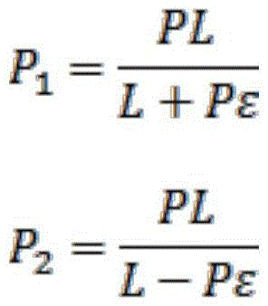
用屈光度φ进行表示,调焦、远景和近景位置可以分别表示为:Represented by diopter φ, the focus, distant view and near view positions can be expressed as:

对应的景深用屈光度可以表示为:The corresponding depth of field can be expressed in diopters as:

可以看出,当用屈光度表示景深时,其只与人眼分辨率ε和瞳径的L有关,计算可得到人眼景深Δ。人眼的调焦范围一般为0.25m到无穷,用屈光度表示为0-4L。因此在设计波导的过程中,如果我们需要n层电控调光板用以满足其成像,各层电控调光板的成像距离Pn根据调焦公式可表示为:It can be seen that when the depth of field is represented by diopters, it is only related to the resolution ε of the human eye and the pupil diameter L, and the depth of field Δ of the human eye can be obtained by calculation. The focusing range of the human eye is generally from 0.25m to infinity, expressed as 0-4L in diopters. Therefore, in the process of designing the waveguide, if we need n layers of electronically controlled dimming panels to meet its imaging requirements, the imaging distance P n of each layer of electronically controlled dimming panels can be expressed as:

其中,L为瞳孔直径,ε表示人眼分辨率,n为电控调光板的层数,n为1时,代表离物镜系统最近的第一层电控调光板。第一层电控调光板的成像距离令n=1计算可得,第二层电控调光板的成像距离令n=2计算可得,依次可计算其他层电控调光板的成像距离。根据上述公式得到的各层电控调光板的成像距离能使人眼在空间内任意焦距处看到清晰图像,最终满足全空间成像。在此段中,成像距离的设置可通过以下但不限于的两种方式:第一、可通过透镜等调焦方式实现不同电控调光板的成像距离;第二、可通过设置电控调光板的位置,而每个电控调光板的成像距离位于其自身位置处。考虑到第二种方案在实际实施时,体积过大,实用性低,通常我们都会选择采用透镜等调焦方式实现不同电控调光板的成像距离,如图3中的透镜3,该透镜同时实现了距离和像的放大,使得电控调光板之间的物理距离可以按比例进行压缩,实现模组的小型化。Among them, L is the diameter of the pupil, ε represents the resolution of the human eye, n is the number of layers of the electronically controlled dimming board, and when n is 1, it represents the first layer of electronically controlled dimming board closest to the objective lens system. The imaging distance of the first layer of electronically controlled dimming panels can be calculated by setting n=1, and the imaging distance of the second layer of electronically controlled dimming panels can be calculated by setting n=2, and the imaging distance of other layers of electronically controlled dimming panels can be calculated in turn distance. The imaging distance of each layer of electronically controlled dimming panels obtained according to the above formula can enable the human eye to see a clear image at any focal length in the space, and finally satisfy the full-space imaging. In this section, the imaging distance can be set in the following two ways but not limited to: first, the imaging distance of different electronically controlled dimming boards can be realized through focusing methods such as lenses; The position of the light panel, while the imaging distance of each electronically controlled dimming panel is located at its own position. Considering that the second solution is too large and has low practicability in actual implementation, we usually choose to use focusing methods such as lenses to achieve the imaging distance of different electronically controlled dimmers, such as
人眼的分辨率ε一般为1’到3’,瞳孔直径L为2mm-5mm。下面我们选取分辨率ε为2’和瞳径的L为3.5mm为例,根据下面公式:The resolution ε of the human eye is generally 1' to 3', and the pupil diameter L is 2mm-5mm. Let’s take the resolution ε as 2’ and the pupil diameter L as 3.5mm as an example, according to the following formula:

其中,以角度表示的分辨率ε在计算时需要转换为弧度进行计算,计算可得到景深Δ为0.3323L,人眼的调焦范围为0.25m到无穷,用屈光度表示为0-4L。因此在设计图像深度调制模组的过程中,如果我们需要12层电控调光板用以满足其成像,各个电控调光板对应的调焦距离为:0.2608m、0.2856m、0.3155m、0.3525m、0.3992m、0.4603m、0.5434m、0.6632m、0.8507m、1.1860m、1.9573m、5.5991m。由于人眼的瞳孔直径和角分辨率,每个平面对于人眼都有个景深范围,12个平面能使景深范围相连,能使人眼在空间内任意位置处清晰成像。能够满足全空间成像,使人眼聚焦在任意位置处都能有个焦平面能清晰成像。Among them, the resolution ε expressed in angle needs to be converted into radians for calculation. The calculation can obtain the depth of field Δ as 0.3323L, and the focusing range of the human eye is from 0.25m to infinity, which is expressed as 0-4L in diopters. Therefore, in the process of designing the image depth modulation module, if we need 12 layers of electronically controlled dimming panels to meet its imaging requirements, the corresponding focusing distances of each electronically controlled dimming panel are: 0.2608m, 0.2856m, 0.3155m, 0.3525m, 0.3992m, 0.4603m, 0.5434m, 0.6632m, 0.8507m, 1.1860m, 1.9573m, 5.5991m. Due to the pupil diameter and angular resolution of the human eye, each plane has a depth of field range for the human eye, and 12 planes can connect the depth of field ranges, enabling the human eye to image clearly at any position in space. It can satisfy full-space imaging, so that the human eye can focus on any position and have a focal plane for clear imaging.
在本发明实施例中,为了防止散射角过大,某个调光板的散射光对排在后面的调光板造成影响,优选每个所述电控调光单元的散射角小于60°且大于5°。比如某个图像的某个位置被第二个调光板的三号电控调光单元散射,第二个调光板的三号电控调光单元散射出的光进入第三个调光板,并且被第二调光板上三号电控调光单元的投影面之外的第三调光板上的电控调光单元散射,这样该图像的该位置会被多个调光板散射,造成干扰。散射角越小,干扰程度越小,但若散射角小于~5°,两个调光板的成像景深相差太小,人眼难以分辨不同调光板的景深,造成深度调制效果不够好。In the embodiment of the present invention, in order to prevent the scattering angle of a dimming board from being too large, and the scattered light of a certain dimming board will affect the dimming boards that are arranged behind, it is preferable that the scattering angle of each electronically controlled dimming unit is less than 60° and greater than 5°. For example, a certain position of an image is scattered by the No. 3 electronically controlled dimming unit of the second dimming board, and the light scattered by the No. 3 electronically controlled dimming unit of the second dimming board enters the third dimming board , and is scattered by the electronically controlled dimming unit on the third dimming board outside the projection surface of No. 3 electronically controlled dimming unit on the second dimming board, so that the position of the image will be scattered by multiple dimming boards , causing interference. The smaller the scattering angle, the smaller the degree of interference, but if the scattering angle is less than ~5°, the difference between the imaging depths of the two dimmers is too small, and it is difficult for the human eye to distinguish the depth of field of different dimmers, resulting in insufficient depth modulation.
上述实施例中的显示模组可运用于近眼显示设备,如虚拟现实VR设备或增强现实AR设备,也可运用于背投显示设备,如电视机、广告屏等。以近眼显示设备为例,近眼显示设备包括一组或两组近眼显示光学系统,每组近眼显示光学系统包括一组本发明实施例中的显示模组和导光系统,如图6,为近眼显示光学系统一种结构示意图,显示模组400中的图像产生模组产生的图像光先经图像深度调制模组,再经物镜系统出射,经耦入系统4耦入导光系统5,由导光系统5出射至人眼。近眼显示设备的结构示意图可参考图7,显示模组400可以设计在镜框两侧,也可以设计在镜腿上,波导系统5可以设计为镜片。The display modules in the above embodiments can be applied to near-eye display devices, such as virtual reality VR devices or augmented reality AR devices, and can also be applied to rear projection display devices, such as TV sets and advertising screens. Taking the near-eye display device as an example, the near-eye display device includes one or two groups of near-eye display optical systems, and each group of near-eye display optical systems includes a set of display modules and light guide systems in the embodiments of the present invention, as shown in Figure 6, which is a near-eye display optical system. A structural schematic diagram of a display optical system. The image light generated by the image generation module in the
具体实施时,近眼显示设备还包括处理器,处理器控制图像产生模组产生图像光的同时,控制图像深度调制模组根据图像光不同区域对应的不同景深,控制每层电控调光板中每个电控调光单元调整为透射状态或散射状态,具体为:During specific implementation, the near-eye display device further includes a processor, and the processor controls the image generation module to generate image light, and at the same time controls the image depth modulation module to control the electronically controlled dimming panel in each layer according to the different depths of field corresponding to different regions of the image light. Each electronically controlled dimming unit is adjusted to a transmission state or a scattering state, specifically:
控制某区域图像光对应景深所对应的电控调光板的对应区域的电控调光单元调整为散射状态,堆叠设置的其他层电控调光板的对应区域的电控调光单元调整为透射状态。同样用图4举例,如图4图像,树对应的景深所对应的电控调光板假设为第一层电控调光板,山对应的景深所对应的电控调光板假设为第二层电控调光板,则第一层电控调光板上被树的图像区域辐照的多个电控调光单元被控制成散射状态,第一层电控调光板上散射状态的电控调光单元在其他层电控调光板上的投影区域的电控调光单元则也须被控制为透射状态;第二层电控调光板上被山的图像区域辐照的多个电控调光单元被控制成散射状态,第二层电控调光板上散射状态电控调光单元在其他层电控调光板上的投影区域的电控调光单元则也须被控制为透射状态。Control the electronically controlled dimming unit in the corresponding area of the electronically controlled dimming board corresponding to the depth of field corresponding to the image light in a certain area to adjust to the scattering state, and adjust the electronically controlled dimming unit in the corresponding area of the electronically controlled dimming board on other layers arranged in a stack to transmission state. Also use Figure 4 as an example, as shown in Figure 4, the electronically controlled dimming board corresponding to the depth of field corresponding to the tree is assumed to be the first layer of electronically controlled dimming board, and the electronically controlled dimming board corresponding to the depth of field corresponding to the mountain is assumed to be the second layer The first layer of electronically controlled dimming boards, the multiple electronically controlled dimming units that are irradiated by the image area of the tree on the first layer of electronically controlled dimming boards are controlled to be in a scattering state, and the scattering state on the first layer of electronically controlled dimming boards The electronically controlled dimming unit in the projection area of the electronically controlled dimming unit on other layers of electronically controlled dimming boards must also be controlled to be in a transmissive state; The first electronically controlled dimming unit is controlled to be in a scattering state, and the electronically controlled dimming units in the projection area of the electronically controlled dimming unit on other layers of electronically controlled dimming boards in the scattering state on the second layer of electronically controlled dimming boards must also be controlled. Control is in transmission state.
本发明采用多层电控调光板以物理方法实现景深效果,使人眼看到的图像更符合现实光场的规律;另外多层电控调光板的成像距离的合理设计,能够更符合现实空间光场的规律,使人眼调焦更自然更接近现实光场中的调焦方式,使人眼更为舒适。最终通过上述两点有效解决现有技术中VR及AR显示中眩晕眼胀的不适感。The present invention uses a multi-layer electronically controlled dimming board to realize the effect of depth of field by a physical method, so that the image seen by the human eye is more in line with the law of the real light field; in addition, the reasonable design of the imaging distance of the multi-layer electronically controlled dimming board can be more in line with reality The law of the spatial light field makes the focusing of the human eye more natural and closer to the focusing method in the real light field, making the human eye more comfortable. Finally, through the above two points, the discomfort of dizziness and eye swelling in VR and AR displays in the prior art can be effectively solved.
本说明书中公开的所有特征,或公开的所有方法或过程中的步骤,除了互相排斥的特征和/或步骤以外,均可以以任何方式组合。All features disclosed in this specification, or steps in all methods or processes disclosed, may be combined in any manner, except for mutually exclusive features and/or steps.
本说明书(包括任何附加权利要求、摘要和附图)中公开的任一特征,除非特别叙述,均可被其他等效或具有类似目的的替代特征加以替换。即,除非特别叙述,每个特征只是一系列等效或类似特征中的一个例子而已。Any feature disclosed in this specification (including any appended claims, abstract and drawings), unless expressly stated otherwise, may be replaced by alternative features which are equivalent or serve a similar purpose. That is, unless expressly stated otherwise, each feature is one example only of a series of equivalent or similar features.
本发明并不局限于前述的具体实施方式。本发明扩展到任何在本说明书中披露的新特征或任何新的组合,以及披露的任一新的方法或过程的步骤或任何新的组合。The present invention is not limited to the foregoing specific embodiments. The present invention extends to any new feature or any new combination disclosed in this specification, and any new method or process step or any new combination disclosed.
本申请的上述技术方案可以进行如下概括:The above-mentioned technical scheme of the present application can be summarized as follows:
A1、一种图像深度调制模组,其特征在于,包括堆叠设置的多层电控调光板,每层电控调光板由若干电控调光单元组成,每个电控调光单元具有独立开关,不同电控调光板上的任一电控调光单元可独立被调控为透射状态或散射状态;A1. An image depth modulation module, characterized in that it includes stacked multi-layer electronically controlled dimming boards, each layer of electronically controlled dimming boards is composed of several electronically controlled dimming units, and each electronically controlled dimming unit has Independent switch, any electronically controlled dimming unit on different electronically controlled dimming boards can be independently adjusted to the transmission state or scattering state;
在所述图像深度调制模组工作时,各层所述电控调光板中的电控调光单元协同被调控为透射状态或散射状态。When the image depth modulation module is working, the electronically controlled dimming units in the electronically controlled dimming panels of each layer are cooperatively adjusted to be in a transmission state or a scattering state.
A2、如A1所述的图像深度调制模组,其特征在于,所述电控调光单元为聚合物稳定液晶光电单元或聚合物分散液晶光电单元。A2. The image depth modulation module as described in A1, wherein the electronically controlled dimming unit is a polymer stabilized liquid crystal photoelectric unit or a polymer dispersed liquid crystal photoelectric unit.
A3、如A2所述的图像深度调制模组,其特征在于,多层电控调光板平行间隔设置。A3. The image depth modulation module as described in A2, characterized in that the multi-layer electronically controlled dimming boards are arranged in parallel and at intervals.
A4、一种显示模组,其特征在于,包括图像产生模组、前述的图像深度调制模组和物镜系统,图像产生模组产生的图像光先经图像深度调制模组,再经物镜系统出射。A4, a display module, characterized in that it includes an image generation module, the aforementioned image depth modulation module and an objective lens system, the image light generated by the image generation module first passes through the image depth modulation module, and then exits through the objective lens system .
A5、如A4所述的显示模组,其特征在于,所述的每层电控调光板上的每个电控调光单元对应图像产生模组产生的一个或多个像素点。A5. The display module as described in A4, wherein each electronically controlled dimming unit on each layer of the electronically controlled dimming board corresponds to one or more pixels generated by the image generating module.
A6、如A5所述的显示模组,其特征在于,所述图像深度调制模组包括堆叠设置的12层电控调光板。A6. The display module as described in A5, wherein the image depth modulation module includes 12 layers of electronically controlled dimming boards stacked.
A7、如A4至A6任一项所述的显示模组,其特征在于,每层电控调光板的成像距离Pn按如下公式设计:A7. The display module as described in any one of A4 to A6 is characterized in that the imaging distance P n of each layer of electronically controlled dimming panels is designed according to the following formula:

其中,L为人眼瞳孔直径,ε表示人眼分辨率,n为电控调光板的层数,n为1时,代表离物镜系统最近的第一层电控调光板。Among them, L is the pupil diameter of the human eye, ε represents the resolution of the human eye, n is the number of layers of the electronically controlled dimming board, and when n is 1, it represents the first layer of the electronically controlled dimming board closest to the objective lens system.
A8、如A7所述的显示模组,其特征在于,ε范围为1’到3’,L范围为2mm-5mm。A8. The display module as described in A7, wherein the range of ε is 1' to 3', and the range of L is 2mm-5mm.
A9、如A7所述的显示模组,其特征在于,ε为2’,L为3.5mm。A9. The display module as described in A7, wherein ε is 2' and L is 3.5mm.
A10、如A4至A6任一项所述的显示模组,其特征在于,每个所述电控调光单元的散射角小于60°且大于5°。A10. The display module according to any one of A4 to A6, wherein the scattering angle of each electronically controlled dimming unit is less than 60° and greater than 5°.
A11、一种近眼显示设备,包括一组或两组近眼显示光学系统,其特征在于,每组近眼显示光学系统包括一组如A4至A10任一项所述的显示模组和导光系统,图像产生模组产生的图像光先经图像深度调制模组,再经物镜系统入射至导光系统,由导光系统出射至人眼。A11. A near-eye display device, including one or two sets of near-eye display optical systems, characterized in that each set of near-eye display optical systems includes a set of display modules and light guide systems as described in any one of A4 to A10, The image light generated by the image generation module first passes through the image depth modulation module, and then enters the light guide system through the objective lens system, and then exits from the light guide system to the human eye.
A12、如A11所述的近眼显示设备,其特征在于,近眼显示设备还包括处理器,处理器控制图像产生模组产生图像光的同时,控制图像深度调制模组根据图像光不同区域对应的不同景深,控制每层电控调光板中每个电控调光单元调整为透射状态或散射状态。A12. The near-eye display device as described in A11, characterized in that the near-eye display device also includes a processor, and the processor controls the image generation module to generate image light, and at the same time controls the image depth modulation module according to the different regions of the image light. Depth of field, to control each electronically controlled dimming unit in each layer of electronically controlled dimming boards to be adjusted to a transmission state or a scattering state.
A13、如A12所述的近眼显示设备,其特征在于,控制图像深度调制模组根据图像光不同区域对应的不同景深,控制每层电控调光板中每个电控调光单元调整为透射状态或散射状态,具体为:A13, the near-eye display device as described in A12, is characterized in that the control image depth modulation module controls each electronically controlled dimming unit in each layer of electronically controlled dimming boards to adjust to transmission according to different depths of field corresponding to different areas of image light state or scatter state, specifically:
控制某区域图像光对应景深所对应的电控调光板的对应区域的电控调光单元调整为散射状态,堆叠设置的其他层电控调光板的对应区域的电控调光单元调整为透射状态。Control the electronically controlled dimming unit in the corresponding area of the electronically controlled dimming board corresponding to the depth of field corresponding to the image light in a certain area to adjust to the scattering state, and adjust the electronically controlled dimming unit in the corresponding area of the electronically controlled dimming board on other layers arranged in a stack to transmission state.
Claims (10)

Priority Applications (1)
| Application Number | Priority Date | Filing Date | Title |
|---|---|---|---|
| CN202211720104.0A CN116413940A (en) | 2018-08-27 | 2018-08-27 | An image depth modulation module, display module and near-eye display device |
Applications Claiming Priority (2)
| Application Number | Priority Date | Filing Date | Title |
|---|---|---|---|
| CN201810980453.3A CN110865480A (en) | 2018-08-27 | 2018-08-27 | Image depth modulation module and application thereof |
| CN202211720104.0A CN116413940A (en) | 2018-08-27 | 2018-08-27 | An image depth modulation module, display module and near-eye display device |
Related Parent Applications (1)
| Application Number | Title | Priority Date | Filing Date |
|---|---|---|---|
| CN201810980453.3A Division CN110865480A (en) | 2018-08-27 | 2018-08-27 | Image depth modulation module and application thereof |
Publications (1)
| Publication Number | Publication Date |
|---|---|
| CN116413940A true CN116413940A (en) | 2023-07-11 |
Family
ID=69651119
Family Applications (2)
| Application Number | Title | Priority Date | Filing Date |
|---|---|---|---|
| CN202211720104.0A Pending CN116413940A (en) | 2018-08-27 | 2018-08-27 | An image depth modulation module, display module and near-eye display device |
| CN201810980453.3A Pending CN110865480A (en) | 2018-08-27 | 2018-08-27 | Image depth modulation module and application thereof |
Family Applications After (1)
| Application Number | Title | Priority Date | Filing Date |
|---|---|---|---|
| CN201810980453.3A Pending CN110865480A (en) | 2018-08-27 | 2018-08-27 | Image depth modulation module and application thereof |
Country Status (1)
| Country | Link |
|---|---|
| CN (2) | CN116413940A (en) |
Families Citing this family (2)
| Publication number | Priority date | Publication date | Assignee | Title |
|---|---|---|---|---|
| CN111751988B (en) * | 2020-06-16 | 2023-03-28 | 深圳珑璟光电科技有限公司 | Depth of field adjusting method and device and binocular near-to-eye display equipment |
| CN112526763B (en) * | 2020-11-20 | 2022-09-27 | 亿信科技发展有限公司 | A light field 3D display device and its driving method |
Citations (4)
| Publication number | Priority date | Publication date | Assignee | Title |
|---|---|---|---|---|
| CN1305619A (en) * | 1998-04-20 | 2001-07-25 | 帝曼斯诺梅迪亚联合有限公司 | Multi-planar volumetric display system and method of operation using three-D anti-aliasing |
| DE102015205871A1 (en) * | 2015-04-01 | 2016-10-06 | Bayerische Motoren Werke Aktiengesellschaft | Display device and field of view display system for a motor vehicle |
| US20170261746A1 (en) * | 2016-03-08 | 2017-09-14 | Sharp Kabushiki Kaisha | Automotive head up display |
| WO2018100003A1 (en) * | 2016-11-30 | 2018-06-07 | Jaguar Land Rover Limited | Multi-depth augmented reality display |
Family Cites Families (3)
| Publication number | Priority date | Publication date | Assignee | Title |
|---|---|---|---|---|
| JP4474853B2 (en) * | 2003-06-30 | 2010-06-09 | 旭硝子株式会社 | Image display device |
| CN112987307B (en) * | 2014-05-30 | 2022-06-28 | 奇跃公司 | Method and system for generating focal planes in virtual and augmented reality |
| CN107894666B (en) * | 2017-10-27 | 2021-01-08 | 杭州光粒科技有限公司 | A head-mounted multi-depth stereoscopic image display system and display method |
-
2018
- 2018-08-27 CN CN202211720104.0A patent/CN116413940A/en active Pending
- 2018-08-27 CN CN201810980453.3A patent/CN110865480A/en active Pending
Patent Citations (4)
| Publication number | Priority date | Publication date | Assignee | Title |
|---|---|---|---|---|
| CN1305619A (en) * | 1998-04-20 | 2001-07-25 | 帝曼斯诺梅迪亚联合有限公司 | Multi-planar volumetric display system and method of operation using three-D anti-aliasing |
| DE102015205871A1 (en) * | 2015-04-01 | 2016-10-06 | Bayerische Motoren Werke Aktiengesellschaft | Display device and field of view display system for a motor vehicle |
| US20170261746A1 (en) * | 2016-03-08 | 2017-09-14 | Sharp Kabushiki Kaisha | Automotive head up display |
| WO2018100003A1 (en) * | 2016-11-30 | 2018-06-07 | Jaguar Land Rover Limited | Multi-depth augmented reality display |
Non-Patent Citations (1)
| Title |
|---|
| 郁道银、谈恒英: "《工程光学》", 31 January 2000, 机械工业出版社, pages: 116 - 117 * |
Also Published As
| Publication number | Publication date |
|---|---|
| CN110865480A (en) | 2020-03-06 |
Similar Documents
| Publication | Publication Date | Title |
|---|---|---|
| JP6700044B2 (en) | Display device | |
| US10718944B2 (en) | Near-eye display device with phase modulation | |
| Yao et al. | Design of an optical see-through light-field near-eye display using a discrete lenslet array | |
| US11009737B1 (en) | Occluder / dimmer based on polarization-selective scatterer and near-eye display containing same | |
| CN103499880B (en) | Head-mounted see through display | |
| CN109507807B (en) | Variable optical range three-dimensional virtual reality display device and method based on light polarization and birefringence | |
| TW201833642A (en) | Liquid crystal diffraction device with nanoscale pattern and manufacturing method thereof | |
| BR112013014975A2 (en) | collimation display with pixel lenses | |
| JP2019530885A (en) | 3D display panel, 3D display device including the same, and manufacturing method thereof | |
| CN112445022A (en) | Liquid crystal display panel and display device | |
| CN111103691A (en) | Near-to-eye display system and device for adjusting transparency by using liquid crystal | |
| CN104932110A (en) | Display device | |
| CN102650792A (en) | Liquid crystal lens and manufacturing method and manufacturing device thereof and 3D (three-dimensional) display device | |
| Ma et al. | Augmented reality autostereoscopic 3D display based on sparse reflection array | |
| CN104159100A (en) | Stereoscopic display device and stereoscopic display method | |
| CN106020431A (en) | Head-mounted electronic device and display thereof | |
| CN116413940A (en) | An image depth modulation module, display module and near-eye display device | |
| Chen et al. | Harnessing and cloaking optical boundary in lens-array based display | |
| CN206115049U (en) | Virtual display panel and display device | |
| CN107111143A (en) | Vision system and viewer | |
| JP2013195536A (en) | Display device, electronic apparatus and control circuit | |
| CN106094342A (en) | A kind of backlight module, display device and display packing | |
| CN115348436B (en) | Stereoscopic image display device capable of reducing grid feeling | |
| CN101119435A (en) | Electronic display apparatus and manufacturing method therefor | |
| CN109031655B (en) | Lens unit and display device |
Legal Events
| Date | Code | Title | Description |
|---|---|---|---|
| PB01 | Publication | ||
| PB01 | Publication | ||
| SE01 | Entry into force of request for substantive examination | ||
| SE01 | Entry into force of request for substantive examination | ||
| RJ01 | Rejection of invention patent application after publication | ||
| RJ01 | Rejection of invention patent application after publication |
Application publication date: 20230711 |