CN116406881A - Wearing equipment - Google Patents
Wearing equipment Download PDFInfo
- Publication number
- CN116406881A CN116406881A CN202111671054.7A CN202111671054A CN116406881A CN 116406881 A CN116406881 A CN 116406881A CN 202111671054 A CN202111671054 A CN 202111671054A CN 116406881 A CN116406881 A CN 116406881A
- Authority
- CN
- China
- Prior art keywords
- key
- buckling piece
- wearable device
- rotating shaft
- host
- Prior art date
- Legal status (The legal status is an assumption and is not a legal conclusion. Google has not performed a legal analysis and makes no representation as to the accuracy of the status listed.)
- Pending
Links
Images


Classifications
-
- A—HUMAN NECESSITIES
- A44—HABERDASHERY; JEWELLERY
- A44C—PERSONAL ADORNMENTS, e.g. JEWELLERY; COINS
- A44C5/00—Bracelets; Wrist-watch straps; Fastenings for bracelets or wrist-watch straps
- A44C5/0007—Bracelets specially adapted for other functions or with means for attaching other articles
-
- A—HUMAN NECESSITIES
- A44—HABERDASHERY; JEWELLERY
- A44C—PERSONAL ADORNMENTS, e.g. JEWELLERY; COINS
- A44C5/00—Bracelets; Wrist-watch straps; Fastenings for bracelets or wrist-watch straps
- A44C5/14—Bracelets; Wrist-watch straps; Fastenings for bracelets or wrist-watch straps characterised by the way of fastening to a wrist-watch or the like
Landscapes
- Clamps And Clips (AREA)
Abstract
Description
技术领域technical field
本发明涉及电子设备技术领域,尤其涉及一种穿戴设备。The invention relates to the technical field of electronic equipment, in particular to a wearable equipment.
背景技术Background technique
随着科技的发展,智能穿戴类电子产品(例如智能手表、智能手环、智能眼镜等)逐渐变得小巧、便携,且能够满足用户的多种需求,如在智能穿戴类电子产品上设置摄像头,以满足用户拍照、视频、通话、扫码等需求。为更方便拍照、视频等,越来越多的智能穿戴类电子产品设计为可翻转式,即翻转式的智能穿戴类电子产品通过增加托板和转轴,使得智能穿戴类电子产品的主机可绕转轴相对于托板翻转,并在主机上设置摄像头、显示屏等,以达到方便拍摄的目的。With the development of technology, smart wearable electronic products (such as smart watches, smart bracelets, smart glasses, etc.) have gradually become small and portable, and can meet the various needs of users, such as setting cameras on smart wearable electronic products , to meet the needs of users for taking photos, videos, calling, scanning codes, etc. In order to make it easier to take pictures and videos, more and more smart wearable electronic products are designed to be reversible, that is, the reversible smart wearable electronic products can make the host of smart wearable electronic products rotate around by adding a support plate and a rotating shaft. The rotating shaft is overturned relative to the supporting plate, and a camera, a display screen, etc. are arranged on the host to achieve the purpose of convenient shooting.
但是,当主机与托板相贴合时,在移动智能穿戴类电子产品的过程中,容易使主机相对于托板产生转动,甚至会使主机与托板之间产生撞击,从而对主机造成一定的损伤。However, when the host is attached to the supporting board, in the process of moving smart wearable electronic products, it is easy to cause the host to rotate relative to the supporting board, and even cause a collision between the host and the supporting board, thereby causing certain damage to the host. damage.
发明内容Contents of the invention
本申请实施例公开了一种穿戴设备,以使主机能够锁止于托板上。The embodiment of the present application discloses a wearable device, so that the host can be locked on the pallet.
为了实现上述目的,本申请实施例公开了一种穿戴设备,包括:In order to achieve the above purpose, the embodiment of the present application discloses a wearable device, including:
托板;pallet;
主机,主机与托板转动连接;The main engine, the main engine is connected with the supporting plate in rotation;
锁止组件,锁止组件包括第一扣合件、第二扣合件以及按键,第一扣合件固定于主机上,第二扣合件连接于托板上,且第二扣合件能够相对于托板在锁止位置和解锁位置之间运动,当第二扣合件处于锁止位置时,第一扣合件与第二扣合件相互扣合,以使主机锁止于托板上,当第二扣合件处于解锁位置时,第一扣合件与第二扣合件相互脱离,以使主机能够相对于托板翻转,按键滑动连接于托板上,按键与第二扣合件相对设置,当按动按键时,按键能够推动第二扣合件向解锁位置运动;The locking assembly, the locking assembly includes a first fastening part, a second fastening part and a button, the first fastening part is fixed on the host, the second fastening part is connected to the supporting plate, and the second fastening part can Relative to the pallet, it moves between the locked position and the unlocked position. When the second fastening part is in the locked position, the first fastening part and the second fastening part are engaged with each other, so that the host is locked on the pallet Above, when the second buckle is in the unlocked position, the first buckle and the second buckle are disengaged from each other, so that the host can turn over relative to the supporting board, the button is slidably connected to the supporting board, and the button and the second buckle The fittings are relatively arranged, and when the button is pressed, the button can push the second snapping part to move to the unlocking position;
复位件,复位件用以向第二扣合件施加向锁止位置运动的弹性力。The reset part is used for applying elastic force to the second fastening part to move to the locking position.
本实施例中,主机与托板转动连接,使主机能够相对于托板翻转,且第一扣合件固定于主机上,第二扣合件连接于托板上,且第二扣合件能够相对于托板在锁止位置和解锁位置之间运动,且当第二扣合件处于锁止位置时,第一扣合件与第二扣合件相互扣合,以使主机锁止于托板上,当第二扣合件处于解锁位置时,第一扣合件与第二扣合件相互脱离,以使主机能够相对于托板翻转;又按键滑动连接于托板上,且按键与第二扣合件相对设置,当按动按键时,按键能够推动第二扣合件向解锁位置运动。由此,当第二扣合件处于锁止位置时,主机锁止于托板上,此时,操作主机上的按钮或显示屏不易使主机相对于托板产生转动,便于对主机上的按钮或显示屏进行操作,且晃动该穿戴设备,主机不易相对于托板产生转动,避免了因此而导致主机与托板发生撞击,从而避免了主机因撞击而受到损伤;当按动按键,第二扣合件向解锁位置运动,使得第二扣合件处于解锁位置时,使得主机能够脱离托板的锁止束缚,从而使得主机能够相对于托板翻转至预设夹角,此时,主机上的前置摄像头可以无需翻转手臂即可进行自拍或者视频,主机上的后置摄像头能够拍摄到对面的景物同时还能够通过显示屏对拍摄图像进行校准,使用方便、舒适。另外,复位件用以向第二扣合件施加向锁止位置运动的弹性力,由此运动至解锁位置的第二扣合件在复位件的作用下能够向锁止位置运动,等待第一扣合件与第二扣合件的再次扣合,使得主机能够锁止于托板上,以方便操作主机上的显示屏或按钮。再者,按键嵌设于托板上,相较于将按键设置于主机上,在主机上节省了按键的占用空间,减小了主机的体积,并且使得按键与主机上的天线之间的距离较远,避免了当按键上设有金属件时对天线产生屏蔽影响,从而避免因此而影响主机对信号的接收和发出。In this embodiment, the host is rotatably connected to the supporting plate so that the host can be turned over relative to the supporting plate, and the first fastening part is fixed on the main machine, the second fastening part is connected to the supporting plate, and the second fastening part can Relative to the pallet, it moves between the locked position and the unlocked position, and when the second fastening part is in the locked position, the first fastening part and the second fastening part are engaged with each other, so that the host is locked on the pallet On the board, when the second fastening part is in the unlocked position, the first fastening part and the second fastening part are disengaged from each other, so that the host can turn over relative to the supporting board; the button is slidably connected to the supporting board, and the button and The second fastening part is oppositely arranged, and when the key is pressed, the key can push the second fastening part to move to the unlocking position. Thus, when the second buckle is in the locked position, the main unit is locked on the supporting plate. At this time, operating the buttons or display screen on the main unit is not easy to make the main unit rotate relative to the supporting plate, which is convenient for the buttons on the main unit to rotate. or the display screen, and the wearable device is shaken, the main unit is not easy to rotate relative to the supporting board, which avoids the collision between the main unit and the supporting board, thus avoiding the main unit being damaged due to the impact; when the button is pressed, the second The buckle moves to the unlocked position, so that when the second buckle is in the unlocked position, the host can break away from the locking restraint of the pallet, so that the host can be flipped to a preset angle relative to the pallet. At this time, the host is on the The front camera can take selfies or videos without flipping the arm, and the rear camera on the main unit can capture the opposite scene and calibrate the captured image through the display screen, which is convenient and comfortable to use. In addition, the reset member is used to apply an elastic force to the second buckle to move to the locked position, so that the second buckle that has moved to the unlocked position can move to the locked position under the action of the reset member, waiting for the first lock. The re-fastening of the fastening part and the second fastening part enables the host to be locked on the supporting plate, so as to facilitate the operation of the display screen or buttons on the host. Furthermore, the buttons are embedded on the supporting plate, compared with setting the buttons on the host, the occupied space of the buttons is saved on the host, the volume of the host is reduced, and the distance between the buttons and the antenna on the host is reduced. Far away, avoiding the shielding effect on the antenna when the button is provided with metal parts, thereby avoiding the influence of the host on the signal receiving and sending out.
在第一方面可能的实现方式中,第二扣合件与托板转动连接,第二扣合件能够相对于托板在锁止位置和解锁位置之间转动。由此,能够使得第二扣合件和第一扣合件相互扣合,以使主机锁止束缚于托板上,或者使得第二扣合件和第一扣合件相互脱离,以使主机脱离托板的锁止束缚。In a possible implementation manner of the first aspect, the second fastening part is rotatably connected to the supporting plate, and the second fastening part can rotate between a locking position and an unlocking position relative to the supporting plate. In this way, the second buckle and the first buckle can be engaged with each other, so that the main unit can be locked and bound to the pallet, or the second buckle and the first buckle can be disengaged from each other, so that the main unit Break free from the locking shackles of the pallet.
在第一方面可能的实现方式中,托板包括板体以及设置于板体上的按键支架,按键滑动连接于按键支架内,按键与第二扣合件抵接,当按动按键时,按键能够推动第二扣合件向解锁位置转动。由此,有效减小了主机按动按键即可使第一扣合件和第二扣合件相互脱离,从而使得主机脱离托板的锁止束缚,操作方便快捷。In a possible implementation of the first aspect, the supporting plate includes a board body and a button bracket arranged on the board body, the button is slidably connected in the button bracket, the button abuts against the second buckle, and when the button is pressed, the button The second buckle can be pushed to rotate to the unlocked position. Thereby, it is effectively reduced that the host can disengage the first fastening part and the second fastening part from each other by pressing the button, so that the main machine is free from the locking constraint of the supporting plate, and the operation is convenient and fast.
在第一方面可能的实现方式中,第一扣合件包括第一卡勾部,第一卡勾部与主机固定连接;In a possible implementation manner of the first aspect, the first fastening member includes a first hook portion, and the first hook portion is fixedly connected to the host;
第二扣合件包括第二卡勾部,第二卡勾部与第一卡勾部对应设置,当第二扣合件处于锁止位置时,第二卡勾部与第一卡勾部相互扣合,当按动按键时,第二卡勾部向远离第一卡勾部的方向转动。由此,通过第一卡勾部和第二卡勾部的相互扣合或者脱离,将主机锁止束缚于托板上或者主机脱离托板的锁止束缚,结构简单易实现。The second buckle part includes a second hook part, and the second hook part is arranged corresponding to the first hook part. When the second buckle part is in the locked position, the second hook part and the first hook part mutually buckle, when the button is pressed, the second hook part rotates away from the first hook part. Thus, the host is locked and restrained on the pallet or the host is detached from the pallet by locking or disengaging the first hook part and the second hook part, and the structure is simple and easy to realize.
在第一方面可能的实现方式中,第二扣合件还包括转轴,第二卡勾部通过转轴与托板转动连接,托板上设有转轴槽,转轴与转轴槽转动配合。由此,可使得第二卡勾部能够稳固的绕转轴在锁止位置和解锁位置之间转动。In a possible implementation manner of the first aspect, the second fastening member further includes a rotating shaft through which the second hook portion is rotatably connected to the supporting plate, a rotating shaft groove is provided on the supporting plate, and the rotating shaft is rotatably matched with the rotating shaft groove. Thus, the second hook portion can stably rotate around the rotation axis between the locking position and the unlocking position.
在第一方面可能的实现方式中,板体上设有凸出部,凸出部与按键支架相对设置,且凸出部朝向按键支架的一侧设有第一弧形槽,按键支架朝向凸出部的一侧设有第二弧形槽,第二弧形槽与第一弧形槽围设形成转轴槽。由此,转轴槽能够进行拆装,方便了转轴的安装和拆卸。In a possible implementation of the first aspect, a protruding part is provided on the board body, and the protruding part is arranged opposite to the key bracket, and the side of the protruding part facing the key support is provided with a first arc-shaped groove, and the key support faces the convex part. One side of the outlet is provided with a second arc-shaped slot, and the second arc-shaped slot surrounds the first arc-shaped slot to form a shaft slot. Thus, the shaft groove can be disassembled, which facilitates the installation and disassembly of the shaft.
在第一方面可能的实现方式中,第二扣合件还包括抵接部,抵接部与第二卡勾部固定连接且沿平行于板体的方向延伸,按键沿平行于板体的方向滑动连接于按键支架内,且按键与抵接部沿平行于板体的方向抵接。由此,按键能够位于托板的一侧,与主机中的天线距离较远,从而减小了按键对主机中的天线的影响。In a possible implementation manner of the first aspect, the second fastening member further includes an abutment portion, the abutment portion is fixedly connected to the second hook portion and extends along a direction parallel to the board body, and the button moves along a direction parallel to the board body The key is slidably connected in the bracket, and the key abuts against the abutting portion along a direction parallel to the board body. Thus, the key can be located on one side of the support plate, and has a relatively long distance from the antenna in the host, thereby reducing the impact of the key on the antenna in the host.
在第一方面可能的实现方式中,复位件包括弹簧,弹簧沿平行于板体的方向延伸,弹簧的一端与抵接部抵接,弹簧的另一端与凸出部抵接,当第二扣合件处于锁止位置时,弹簧处于压缩状态,以使第二扣合件保持在锁止位置。由此,可为第二扣合件再次与第一扣合件相互扣合做好准备,并能够使按键恢复至原位,以方便对按键再次进行按压。In a possible implementation manner of the first aspect, the return member includes a spring, and the spring extends in a direction parallel to the plate body, one end of the spring abuts against the abutting portion, and the other end of the spring abuts against the protruding portion, when the second buckle When the locking part is in the locking position, the spring is in a compressed state to keep the second locking part in the locking position. In this way, preparations can be made for the second fastening part to be fastened with the first fastening part again, and the button can be restored to its original position, so as to facilitate pressing the button again.
在第一方面可能的实现方式中,抵接部朝向凸出部的一侧设有第一安装柱,凸出部上朝向抵接部的一侧对应设有第二安装柱,弹簧的一端套设于第一安装柱上,弹簧的另一端套设于第二安装柱上。由此,使得弹簧能够始终连接在抵接部与凸出部之间为第二扣合件提供弹性力,并且易于弹簧拆卸,方便了后续对弹簧的维护和更换。In a possible implementation of the first aspect, a first mounting column is provided on the side of the abutting portion facing the protruding portion, and a second mounting post is correspondingly provided on the side of the protruding portion facing the abutting portion, and one end of the spring covers It is arranged on the first mounting post, and the other end of the spring is sleeved on the second mounting post. Thus, the spring can always be connected between the abutting portion and the protruding portion to provide elastic force for the second fastening member, and the spring is easy to disassemble, which facilitates subsequent maintenance and replacement of the spring.
在第一方面可能的实现方式中,第二扣合件包括转轴套,托板上设有表带轴,转轴套套设于表带轴上,以使第二卡勾部能够绕表带轴在锁止位置和解锁位置之间转动。由此,转轴套与表带共用一个表带轴,节省了零件。In a possible implementation of the first aspect, the second fastening member includes a rotating shaft sleeve, a strap shaft is arranged on the support plate, and the rotating shaft sleeve is sleeved on the strap shaft, so that the second hook portion can rotate around the strap shaft. Rotate between locked and unlocked positions. Thus, the rotating shaft sleeve and the watch band share a watch band shaft, which saves parts.
在第一方面可能的实现方式中,板体背离主机的一侧设有凸耳,凸耳内开设有第一安装孔和第二安装孔,第二安装孔的孔壁上开设有避让口,第二卡勾部穿过避让口与转轴套固定连接,第一安装孔和第二安装孔同轴设置,且第二安装孔的直径大于第一安装孔的直径,转轴套与第二安装孔转动配合,表带轴穿设于第一安装孔和转轴套内。由此,可使得套设于表带轴上的转轴套仅能够在第二安装孔内相对于表带轴转动,防止了第二卡勾部在相对于托板转动的同时还会沿第一方向滑动,以使得第二卡勾部能够与第一卡勾部相扣合。In a possible implementation of the first aspect, lugs are provided on the side of the board away from the host, and a first mounting hole and a second mounting hole are opened in the lugs, and an escape opening is opened on the wall of the second mounting hole. The second hook part is fixedly connected with the rotating shaft sleeve through the avoidance port, the first mounting hole and the second mounting hole are coaxially arranged, and the diameter of the second mounting hole is larger than the diameter of the first mounting hole, and the rotating shaft sleeve and the second mounting hole Rotationally matched, the strap shaft is passed through the first mounting hole and the rotating shaft sleeve. As a result, the rotating shaft sleeve sleeved on the strap shaft can only be rotated relative to the strap shaft in the second mounting hole, preventing the second hook part from rotating along the first hook while rotating relative to the supporting plate. direction, so that the second hook part can engage with the first hook part.
在第一方面可能的实现方式中,第二扣合件还包括抵接部,抵接部与第二卡勾部固定连接且沿平行于板体的方向延伸,按键沿垂直于板体的方向滑动连接于按键支架内,且按键与抵接部沿垂直于板体的方向抵接。由此,按键位于板体上朝向主机的一侧,相对于按键位于主机上,节省了主机的占用空间。In a possible implementation manner of the first aspect, the second fastening member further includes an abutment portion, the abutment portion is fixedly connected to the second hook portion and extends along a direction parallel to the board body, and the key is along a direction perpendicular to the board body The key is slidingly connected in the bracket, and the key abuts against the abutting portion along a direction perpendicular to the board body. Therefore, the key is located on the side of the board body facing the host, and is located on the host relative to the key, which saves the occupied space of the host.
在第一方面可能的实现方式中,复位件包括弹簧,弹簧沿垂直于板体的方向延伸,弹簧的一端与抵接部连接,弹簧的另一端与凸出部连接,弹簧用以向第二扣合件施加向锁止位置转动的弹性力,且当第二扣合件处于锁止位置时,弹簧处于压缩状态。In a possible implementation manner of the first aspect, the return member includes a spring, and the spring extends in a direction perpendicular to the plate body, and one end of the spring is connected to the abutting portion, and the other end of the spring is connected to the protruding portion, and the spring is used to move toward the second The fastening part exerts an elastic force to rotate toward the locked position, and when the second fastened part is at the locked position, the spring is in a compressed state.
由此,弹簧沿垂直于板体的方向延伸,以使弹簧提供的弹性力沿垂直于板体的方向且与按压按键的压力的方向相反,从而能够使得第二扣合件快速从解锁位置转动至锁止位置,并使得按键能够沿垂直于板体的方向滑动至原位。Thus, the spring extends in a direction perpendicular to the plate body, so that the elastic force provided by the spring is in a direction perpendicular to the plate body and opposite to the pressure direction of pressing the button, so that the second buckle can be quickly rotated from the unlocked position to the locked position, and enable the button to slide to the original position along the direction perpendicular to the board body.
在第一方面可能的实现方式中,托板上朝向按键的一侧设有容纳槽,按键支架嵌设于容纳槽内,按键支架的一端面与容纳槽的底部抵接,按键支架的另一端面与容纳槽的端面平齐。由此,可使得按键支架嵌设于容纳槽内,使得穿戴设备的外观整齐大方。In a possible implementation of the first aspect, a receiving groove is provided on the side facing the key on the supporting plate, and the button bracket is embedded in the receiving groove, one end surface of the button bracket abuts against the bottom of the receiving groove, and the other The end face is flush with the end face of the receiving groove. Thus, the key bracket can be embedded in the receiving groove, so that the appearance of the wearable device is neat and elegant.
在第一方面可能的实现方式中,按键支架包括封装板,封装板具有相背的第一表面和第二表面,第一表面与容纳槽的端面平齐,封装板上开设有导向孔,导向孔贯穿第一表面和第二表面;In a possible implementation manner of the first aspect, the key support includes a packaging board, the packaging board has a first surface and a second surface opposite to each other, the first surface is flush with the end surface of the receiving groove, and a guide hole is opened on the packaging board to guide the a hole extends through the first surface and the second surface;
按键包括:Keys include:
按压部,按压部滑动连接于导向孔内;The pressing part is slidably connected in the guide hole;
滑动部,滑动部与按压部固定连接,滑动部远离按压部的一面与抵接部抵接,当第二扣合件处于锁止位置时,滑动部朝向按压部的一面与第二表面抵接。由此,可防止按键在弹簧的弹性力的作用下滑出按键支架,以保证按键的正常使用。The sliding part, the sliding part is fixedly connected with the pressing part, the side of the sliding part away from the pressing part abuts against the abutting part, and when the second fastener is in the locked position, the side of the sliding part facing the pressing part abuts against the second surface . As a result, the key can be prevented from slipping out of the key bracket under the action of the elastic force of the spring, so as to ensure the normal use of the key.
在第一方面可能的实现方式中,按键支架上设有卡接凸起,卡接凸起的材料为弹性材料,容纳槽的侧壁上对应设有卡槽,卡接凸起卡接于卡槽内,以阻止按键支架向容纳槽外移动。由此,按键支架能够固定于容纳槽内。In a possible implementation of the first aspect, the button bracket is provided with a locking protrusion, and the material of the locking protrusion is an elastic material. In the groove, to prevent the key bracket from moving out of the receiving groove. Thus, the key bracket can be fixed in the receiving groove.
在第一方面可能的实现方式中,第一卡勾部朝向板体的一侧设有第一导向面,第二卡勾部朝向主机的一侧设有第二导向面,当主机向托板转动时,第一导向面能够挤压第二导向面以使第二扣合件从锁止位置向解锁位置转动。由此,通过第一导向面和第二导向面的相互配合,当主机向托板转动时,按压主机即可使得第二扣合件从锁止位置向解锁位置转动,以实现第一扣合件与第二扣合件的相互扣合。In a possible implementation of the first aspect, the first hook part is provided with a first guide surface on the side facing the plate body, and the second hook part is provided with a second guide surface on the side facing the main machine. When rotating, the first guide surface can press the second guide surface to make the second buckle rotate from the locking position to the unlocking position. Thus, through the mutual cooperation of the first guide surface and the second guide surface, when the host turns to the supporting plate, pressing the host can make the second buckle rotate from the locked position to the unlocked position, so as to realize the first buckle The mutual fastening of the first part and the second fastening part.
附图说明Description of drawings
为了更清楚地说明本发明实施例中的技术方案,下面将对实施例中所需要使用的附图作简单地介绍,显而易见地,下面描述中的附图仅仅是本发明的一些实施例,对于本领域普通技术人员来讲,在不付出创造性劳动的前提下,还可以根据这些附图获得其他的附图。In order to more clearly illustrate the technical solutions in the embodiments of the present invention, the following will briefly introduce the accompanying drawings that need to be used in the embodiments. Obviously, the accompanying drawings in the following description are only some embodiments of the present invention. For Those of ordinary skill in the art can also obtain other drawings based on these drawings without making creative efforts.
图1是本申请实施例提供的一种穿戴设备的立体图之一;FIG. 1 is one of perspective views of a wearable device provided in an embodiment of the present application;
图2是图1的爆炸图;Figure 2 is an exploded view of Figure 1;
图3是图1的局部剖视图;Fig. 3 is a partial sectional view of Fig. 1;
图4是本申请实施例提供的一种穿戴设备的立体图之二;Fig. 4 is the second perspective view of a wearable device provided by the embodiment of the present application;
图5是图4的爆炸图;Figure 5 is an exploded view of Figure 4;
图6是图4的局部剖视图;Fig. 6 is a partial sectional view of Fig. 4;
图7是本申请实施例提供的主机、第一扣合件和第二扣合件配合的立体图;Fig. 7 is a perspective view of the cooperation of the host, the first fastening part and the second fastening part provided by the embodiment of the present application;
图8是图7中的A放大图;Figure 8 is an enlarged view of A in Figure 7;
图9是本申请实施例提供的托板的立体图之一;Fig. 9 is one of the perspective views of the pallet provided by the embodiment of the present application;
图10是本申请实施例提供的按键支架的立体图之一;Fig. 10 is one of the perspective views of the button bracket provided by the embodiment of the present application;
图11是本申请实施例提供的第二扣合件的立体图之一;Fig. 11 is one of the perspective views of the second fastener provided by the embodiment of the present application;
图12是本申请实施例提供的第二扣合件和按键相互配合的立体图之一;Fig. 12 is one of the three-dimensional views of the cooperation between the second fastener and the button provided by the embodiment of the present application;
图13是本申请实施例提供的托板与表带轴的爆炸图;Fig. 13 is an exploded view of the pallet and strap shaft provided by the embodiment of the present application;
图14是本申请实施例提供的托板的立体图之二;Figure 14 is the second perspective view of the pallet provided by the embodiment of the present application;
图15是本申请实施例提供的第二扣合件的立体图之二;Fig. 15 is the second perspective view of the second fastener provided by the embodiment of the present application;
图16是本申请实施例提供的第二扣合件和按键相互配合的立体图之二;Fig. 16 is the second perspective view of the cooperation between the second buckle and the button provided by the embodiment of the present application;
图17是本申请实施例提供的按键支架的立体图之二;Fig. 17 is the second perspective view of the key bracket provided by the embodiment of the present application;
图18是本申请实施例提供的按键支架的立体图之三;Fig. 18 is the third perspective view of the key bracket provided by the embodiment of the present application;
图19是本申请实施例提供的按键的立体图。Fig. 19 is a perspective view of a button provided by an embodiment of the present application.
附图标记说明:Explanation of reference signs:
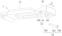
1-托板;11-板体;12-凸出部;121-容纳槽;1211-卡槽;122-第一弧形槽;123-第三弧形槽;124-第二安装柱;13-按键支架;131-封装板;1311-第一表面;1312-第二表面;1313-导向孔;132-支撑板;133-卡接凸起;134-第二弧形槽;14-凸耳;141-第一安装孔;142-第二安装孔;143-第三安装孔;15-表带轴;151-第一表带轴;152-第二表带轴;153-固定螺钉;1-supporting plate; 11-board body; 12-protruding part; 121-accommodating groove; 1211-carding groove; 122-first arc groove; 123-third arc groove; -button bracket; 131-package board; 1311-first surface; 1312-second surface; 1313-guide hole; 132-support plate; ; 141-the first mounting hole; 142-the second mounting hole; 143-the third mounting hole; 15-strap shaft; 151-the first strap shaft; 152-the second strap shaft;
2-主机;21-显示面;2-host; 21-display surface;
3-锁止组件;31-第一扣合件;311-第一卡勾部;3111-第一卡勾;31111-第一导向面;3112-第一连杆;32-第二扣合件;321-第二卡勾部;3211-第二卡勾;32111-第二导向面;3212-第二连杆;322-转轴;3221-第一转轴;3222-第二转轴;323-转轴套;324-抵接部;3241-第一安装柱;33-按键;331-按压部;332-滑动部;3321-抵接槽;3-locking assembly; 31-the first buckle; 311-the first hook part; 3111-the first hook; 31111-the first guide surface; 3112-the first connecting rod; 32-the second buckle ; 321-the second hook part; 3211-the second hook; 32111-the second guide surface; ; 324-butting part; 3241-the first installation column; 33-button; 331-pressing part; 332-sliding part; 3321-butting groove;
4-复位件;41-弹簧。4-return part; 41-spring.
具体实施方式Detailed ways
下面将结合本发明实施例中的附图,对本发明实施例中的技术方案进行清楚、完整地描述,显然,所描述的实施例仅是本发明一部分实施例,而不是全部的实施例。基于本发明中的实施例,本领域普通技术人员在没有做出创造性劳动前提下所获得的所有其他实施例,都属于本发明保护的范围。The following will clearly and completely describe the technical solutions in the embodiments of the present invention with reference to the accompanying drawings in the embodiments of the present invention. Obviously, the described embodiments are only some of the embodiments of the present invention, not all of them. Based on the embodiments of the present invention, all other embodiments obtained by persons of ordinary skill in the art without making creative efforts belong to the protection scope of the present invention.
在本发明中,术语“上”、“下”、“左”、“右”、“前”、“后”、“顶”、“底”、“内”、“外”、“中”、“竖直”、“水平”、“横向”、“纵向”等指示的方位或位置关系为基于附图所示的方位或位置关系。这些术语主要是为了更好地描述本发明及其实施例,并非用于限定所指示的装置、元件或组成部分必须具有特定方位,或以特定方位进行构造和操作。In the present invention, the terms "upper", "lower", "left", "right", "front", "rear", "top", "bottom", "inner", "outer", "middle", The orientations or positional relationships indicated by "vertical", "horizontal", "horizontal", and "longitudinal" are based on the orientations or positional relationships shown in the drawings. These terms are mainly used to better describe the present invention and its embodiments, and are not intended to limit that the indicated device, element or component must have a specific orientation, or be constructed and operated in a specific orientation.
并且,上述部分术语除了可以用于表示方位或位置关系以外,还可能用于表示其他含义,例如术语“上”在某些情况下也可能用于表示某种依附关系或连接关系。对于本领域普通技术人员而言,可以根据具体情况理解这些术语在本发明中的具体含义。Moreover, some of the above terms may be used to indicate other meanings besides orientation or positional relationship, for example, the term "upper" may also be used to indicate a certain attachment relationship or connection relationship in some cases. Those skilled in the art can understand the specific meanings of these terms in the present invention according to specific situations.
此外,术语“安装”、“设置”、“设有”、“连接”、“相连”应做广义理解。例如,可以是固定连接,可拆卸连接,或整体式构造;可以是机械连接,或电连接;可以是直接相连,或者是通过中间媒介间接相连,又或者是两个装置、元件或组成部分之间内部的连通。对于本领域普通技术人员而言,可以根据具体情况理解上述术语在本发明中的具体含义。Furthermore, the terms "installed", "disposed", "provided", "connected", "connected" are to be interpreted broadly. For example, it may be a fixed connection, a detachable connection, or an integral structure; it may be a mechanical connection or an electrical connection; it may be a direct connection or an indirect connection through an intermediary; internal connectivity. Those of ordinary skill in the art can understand the specific meanings of the above terms in the present invention according to specific situations.
此外,术语“第一”、“第二”等主要是用于区分不同的装置、元件或组成部分(具体的种类和构造可能相同也可能不同),并非用于表明或暗示所指示装置、元件或组成部分的相对重要性和数量。除非另有说明,“多个”的含义为两个或两个以上。In addition, the terms "first", "second", etc. are mainly used to distinguish different devices, elements or components (the specific types and structures may be the same or different), and are not used to indicate or imply that the indicated devices, elements Or the relative importance and number of components. Unless otherwise specified, "plurality" means two or more.
随着科技的发展,智能穿戴类电子产品(例如智能手表、智能手环、智能眼镜等)逐渐变得小巧、便携,且能够满足用户的多种需求,如在智能穿戴类电子产品上设置摄像头,以满足用户拍照、视频、通话、扫码等需求。为更方便拍照、视频等,越来越多的智能穿戴类电子产品设计为可翻转式,即翻转式的智能穿戴类电子产品通过增加托板和转轴,使得智能穿戴类电子产品的主机可绕转轴相对于托板翻转,并在主机上设置前置摄像头、后置摄像头、显示屏等,以达到方便拍摄的目的。With the development of technology, smart wearable electronic products (such as smart watches, smart bracelets, smart glasses, etc.) have gradually become small and portable, and can meet the various needs of users, such as setting cameras on smart wearable electronic products , to meet the needs of users for taking photos, videos, calling, scanning codes, etc. In order to make it easier to take pictures and videos, more and more smart wearable electronic products are designed to be reversible, that is, the reversible smart wearable electronic products can make the host of smart wearable electronic products rotate around by adding a support plate and a rotating shaft. The rotating shaft is overturned relative to the supporting plate, and a front camera, a rear camera, a display screen, etc. are arranged on the host to achieve the purpose of convenient shooting.
由此,当主机处于与托板相贴合的位置时,操作主机上的显示屏、按钮等,主机不易相对于托板产生移动,方便了显示屏、按钮等的操作;当主机翻转至与托板呈预设夹角时,用户无需翻转手臂将产品抬起即可使用主机上的前置摄像头进行自拍、视频,或者无需翻转产品即可使用后置摄像头拍摄对面的景物,操作方便。As a result, when the host is in a position that fits the supporting plate, the host is not easy to move relative to the supporting plate by operating the display, buttons, etc. on the host, which facilitates the operation of the display, buttons, etc.; When the pallet is at a preset angle, the user can use the front camera on the main unit to take selfies and videos without flipping the arm to lift the product, or use the rear camera to take pictures of the opposite scene without flipping the product, which is easy to operate.
但是,当主机与托板相贴合时,晃动智能穿戴类电子产品的过程中,容易使主机相对于托板产生转动,甚至会使主机与托板之间产生撞击,从而对主机造成一定的损伤。However, when the host is attached to the supporting board, it is easy to cause the host to rotate relative to the supporting board during the process of shaking the smart wearable electronic product, and even cause a collision between the host and the supporting board, thereby causing certain damage to the host. damage.
鉴于此,本发明提供了一种穿戴设备,以使主机能够锁止束缚于托板上,且能够有效减小锁止机构在主机上的占用空间。In view of this, the present invention provides a wearable device, so that the host can be locked and bound on the pallet, and can effectively reduce the space occupied by the locking mechanism on the host.
下面将结合具体实施例和附图对本申请的技术方案进行详细说明。The technical solution of the present application will be described in detail below in conjunction with specific embodiments and accompanying drawings.
实施例一Embodiment one
本申请实施例提供了一种穿戴设备,如图1-图6所示,穿戴设备包括:托板1、主机2、锁止组件3及复位件4;主机2与托板1转动连接,锁止组件3包括第一扣合件31、第二扣合件32以及按键33,第一扣合件31固定于主机2上,第二扣合件32连接于托板1上,且第二扣合件32能够相对于托板1在锁止位置和解锁位置之间运动,当第二扣合件32处于锁止位置时,第一扣合件31与第二扣合件32相互扣合,以使主机2锁止于托板1上,当第二扣合件32处于解锁位置时,第一扣合件31与第二扣合件32相互脱离,以使主机2能够相对于托板1翻转,按键33滑动连接于托板1上,按键33与第二扣合件32相对设置,当按动按键33时,按键33能够推动第二扣合件32向解锁位置运动,复位件4用以向第二扣合件32施加向锁止位置运动的弹性力。The embodiment of the present application provides a wearable device, as shown in Figure 1-6, the wearable device includes: a supporting
本实施例中,主机2与托板1转动连接,使主机2能够相对于托板1翻转,且主机2上可以设置显示面21、穿戴面以及天线,显示面21上可以设置有前置摄像头、按钮以及显示屏,穿戴面上可以设置有后置摄像头,穿戴面能够与托板1相贴合。In this embodiment, the
上述的第一扣合件31固定于主机2上,第二扣合件32连接于托板1上,且第二扣合件32能够相对于托板1在锁止位置和解锁位置之间运动,且当第二扣合件32处于锁止位置时,第一扣合件31与第二扣合件32相互扣合,以使主机2锁止于托板1上,当第二扣合件32处于解锁位置时,第一扣合件31与第二扣合件32相互脱离,以使主机2能够相对于托板1翻转;又按键33滑动连接于托板1上,且按键33与第二扣合件32相对设置,当按动按键33时,按键33能够推动第二扣合件32向解锁位置运动。由此,当第二扣合件32处于锁止位置时,主机2锁止于托板1上,此时,操作主机2上的按钮或显示屏不易使主机2相对于托板1产生转动,便于对主机2上的按钮或显示屏进行操作,且晃动该穿戴设备,主机2不易相对于托板1产生转动,避免了因此而导致主机2与托板1之间发生撞击,从而避免了主机2因撞击而受到损伤;当按动按键33,第二扣合件32向解锁位置运动,使得第二扣合件32处于解锁位置时,主机2能够脱离托板1的锁止束缚,从而使得主机2能够相对于托板1翻转至预设夹角,此时,主机2上的前置摄像头可以无需翻转手臂即可进行自拍或者视频,主机2上的后置摄像头能够拍摄到对面的景物同时还能够通过显示屏对拍摄图像进行校准,使用方便、舒适。另外,复位件4用以向第二扣合件32施加向锁止位置运动的弹性力,由此运动至解锁位置的第二扣合件32在复位件4的作用下能够向锁止位置运动,等待第一扣合件31与第二扣合件32的再次扣合,使得主机2能够锁止于托板1上,以方便操作主机2上的显示屏或按钮。再者,按键33嵌设于托板1上,相较于将按键33设置于主机2上,在主机2上节省了按键33的占用空间,减小了主机2的体积,并且使得按键33与主机2上的天线之间的距离较远,避免了当按键33上设有金属件时对天线产生屏蔽影响,从而避免了因此而影响主机2对信号的接收和发出。The above-mentioned
需要说明的是,上述的预设夹角是指根据需要,主机2翻转后主机2与托板1之间的夹角,夹角可以是80°、可以是90°、也可以是100°,在此不做限定。It should be noted that the above-mentioned preset angle refers to the angle between the
上述的第二扣合件32连接于托板1上可以有多种形式。在一种可能的形式中,第二扣合件32可以滑动连接于托板1上,即托板1上设置有滑槽,第二扣合件32滑动配合于滑槽内,以使第二扣合件32能够相对于托板1在锁止位置和解锁位置之间滑动,从而使得第二扣合件32和第一扣合件31相互扣合或者相互脱离。在另一种可能的形式中,第二扣合件32与托板1转动连接,第二扣合件32能够相对于托板1在锁止位置和解锁位置之间转动,从而使得第二扣合件32和第一扣合件31相互扣合或者相互脱离。以下将对第二扣合件32与托板1滑动连接的形式进行详细阐述。The above-mentioned
具体地,如图3和图6所示,托板1包括板体11以及设置于板体11上的按键支架13,板体11上设有凸出部12,凸出部12与按键支架13相对设置,按键33滑动连接于按键支架13内,且按键33与第二扣合件32相抵接,当按动按键33时,按键33能够推动第二扣合件32向解锁位置转动,以使第一扣合件31和第二扣合件32相互脱离,从而使得主机2脱离托板1的锁止束缚,操作方便快捷。Specifically, as shown in FIG. 3 and FIG. 6 , the
另外,如图7所示,第一扣合件31包括第一卡勾部311,第一卡勾部311包括第一连杆3112和与第一连杆3112固定连接的第一卡勾3111,第一连杆3112的一端与主机2固定连接,第一连杆3112的另一端向板体11的方向延伸,且与第一卡勾3111固定连接。第二扣合件32包括第二卡勾部321,第二卡勾部321包括第二连杆3212和与第二连杆3212固定连接的第二卡勾3211,第二卡勾3211与第一卡勾3111对应设置,且当第二扣合件32处于锁止位置时,第二卡勾3211与第一卡勾3111相互扣合,当按动按键33时,第二卡勾3211向远离第一卡勾3111的方向转动,以使第二卡勾3211与第一卡勾3111相互脱离,操作简便快捷,且第一卡勾部311和第二卡勾部321的结构简单易实现。并且,第一卡勾3111沿第一方向(即X方向)的宽度宽于第二卡勾3211沿第一方向X的宽度,以防止第二扣合件32位于锁止位置时第二卡勾3211不能完全与第一卡勾3111相互扣合,使得第二卡勾3211和第一卡勾3111的相互扣合更加牢固。并且,第一扣合部可以是两个,相应的第二卡勾部321可以是两个,且两个第一扣合部和两个第二卡勾部321关于板体11的宽度上的中心线对称。In addition, as shown in FIG. 7 , the
需要说明的是,上述的板体11的宽度是指板体11沿第一方向X的尺寸。It should be noted that the above-mentioned width of the
如图7和图8所示,第一卡勾3111朝向板体11的一侧设有第一导向面31111,第二卡勾部321朝向主机2的一侧设有第二导向面32111,当主机2向托板1转动时,按压主机2使得第一导向面31111能够挤压第二导向面32111以使第二卡勾3211向远离第一卡勾3111的方向转动,即能够使得第二扣合件32从锁止位置向解锁位置转动,直至主机2与托板1相贴合,第二扣合件32在复位键的作用下从解锁位置转动至锁止位置,使得第二卡勾3211与第一卡勾3111相互扣合,从而将主机2锁止于托板1上。As shown in Figures 7 and 8, the
上述的第二扣合件32能够相对于托板1转动,以使得第二卡勾3211相对于托板1在锁止位置和解锁位置之间转动。并且第二扣合件32与托板1之间的转动连接可以通过多种方式实现,在一种可能实现的方式中,第二扣合件32除包括上述的第二卡勾部321外,还包括转轴322,第二连杆3212朝向板体11的一端与转轴322的外壁固定连接,第二卡勾部321通过转轴322与托板1转动连接,托板1上相应的设有转轴槽,转轴322转动配合于转轴槽内,以使第二卡勾部321能够稳固的绕转轴322在锁止位置和解锁位置之间转动。The above-mentioned
具体地,如图9-图11所示,板体11上的凸出部12朝向按键支架13的一侧设有第一弧形槽122,按键支架13朝向凸出部12的一侧设有第二弧形槽134,第二弧形槽134与第一弧形槽122围设形成转轴槽;转轴322包括第一转轴3221,第一转轴3221可在转轴槽内转动,从而使得第二卡勾3211能够相对于板体11转动,且转轴槽能够拆装,方便了转轴322的安装和拆卸。进一步的,转轴322还包括第二转轴3222,第一转轴3221的两个端面上分别与一个第二转轴3222固定连接,且第二转轴3222的直径小于第一转轴3221的直径,相应的,凸出部12朝向按键支架13的一侧还设有两个第三弧形槽123,第三弧形槽123位于第一弧形槽122的两侧,按键支架13朝向凸出部12的一端与第三弧形槽123形成第二转轴槽,第二转轴3222位于第二转轴槽内转动,且第二转轴3222与第二转轴槽之间的间隙较小,以使转轴322在转动时不易出现晃动。Specifically, as shown in FIGS. 9-11 , the protruding
如图11和图12所示,第二扣合件32还包括抵接部324,抵接部324与第二连杆3212朝向按键支架13的一面固定连接且沿平行于板体11的方向延伸,即抵接部324的两端分别与一个第二连杆3212固定连接,且抵接部324沿第二方向(即Y方向)的厚度尺寸小于第二连杆3212沿第一方向X的宽度尺寸,抵接部324沿垂直于板体11方向的宽度尺寸大于抵接部324沿第二方向Y的厚度尺寸;按键33沿平行于板体11的方向滑动连接于按键支架13内,且按键33与抵接部324沿平行于板体11的方向相互抵接,即按键33与抵接部324沿垂直于板体11方向的一面相互抵接。由此,能够使得按键33位于板体11的一侧面上,与主机2中的天线距离较远,从而减小了按键33对主机2中的天线的影响。另外,按键33能够与抵接部324较宽的一面相互抵接,使得抵接部324能够承受较大的按压力。且按键33朝向抵接部324的一端的端面上设有抵接槽3321,抵接槽3321的宽度与抵接部324相对应,抵接部324位于抵接槽3321内,由此,可使得按键33与抵接部324的抵接稳定牢固,从而在按压按键33时能够使得第二扣合件32稳定的从锁止位置转动至解锁位置。As shown in FIG. 11 and FIG. 12 , the
在另一种可能实现的方式中,如图13-图15所示,第二扣合件32包括转轴套323,第二连杆3212朝向板体11的一端与转轴套323的外壁固定连接,托板1上设有用于连接表带的表带轴15,转轴套323套设于表带轴15上,转轴套323能够相对于表带轴15转动,以使第二卡勾部321能够绕表带轴15在锁止位置和解锁位置之间转动。并且,转轴套323与表带共用一个表带轴15,节省了零件,减小了托板1的体积。In another possible implementation manner, as shown in FIGS. 13-15 , the
具体地,如图13和图14所示,板体11上背离主机2的一侧可以设有两个凸耳14,两个凸耳14沿第一方向X相对设置,且凸耳14内开设有第一安装孔141和第二安装孔142,第一安装孔141沿第一方向X贯穿凸耳14,第二安装孔142位于凸耳14内靠近两个凸耳14相对的端面的位置处,第二安装孔142朝向第二卡勾3211的孔壁上开设有避让口,第二连杆3212穿过避让口与转轴套323固定连接,第二连杆3212能够在避让孔内转动,以使转轴套323相对于表带轴15转动时,第二卡勾3211能够相对于托班转动,从而能够使第二卡勾3211与第一卡勾3111相互扣合或者相互脱离。Specifically, as shown in Figures 13 and 14, two
并且第一安装孔141和第二安装孔142同轴设置,第二安装孔142的直径大于第一安装孔141的直径,转轴套323与第二安装孔142转动配合,表带轴15穿设于第一安装孔141和转轴套323内,并将表带轴15与凸耳14固定连接,以使套设于表带轴15上的转轴套323仅能够在第二安装孔142内相对于表带轴15转动,防止了第二卡勾3211在相对于托板1转动的同时还会沿第一方向X滑动,从而保证了第二扣合件32转动至锁止位置时,第一卡勾3111和第二卡勾3211能够相互扣合。And the first mounting
如图13和图14所示,凸耳14上靠近两个凸耳14相背的端面上还开设有第三安装孔143,第三安装孔143与第一安装孔141和第二安装孔142同轴设置,且第三安装孔143的直径大于第一安装孔141的直径,即第三安装孔143与第一安装孔141之间形成台阶面。相应的,表带轴15包括第一表带轴151和第二表带轴152,第一表带轴151的一端与第二表带轴152固定连接,即第一表带轴151可以与第二表带轴152一体成形,且第一表带轴151的直径小于和第二表带轴152的直径,即第二表带轴152与第一表带轴151之间形成有台阶面,第二表带轴152穿设于其中一个凸耳14上的第三安装孔143内;第一表带轴151的另一端的端面上开设有螺纹孔,固定螺钉153与螺纹孔通过螺纹连接,固定螺钉153的螺钉头穿设于另一凸耳14上的第三安装孔143内,以将表带轴15固定于凸耳14上,防止了表带轴15从凸耳14上脱离,从而避免了因此而使得转轴套323脱离表带轴15,保证了第一卡勾3111和第二卡勾3211之间相互扣合的动作或者相互脱离的动作的顺利完成。As shown in Fig. 13 and Fig. 14, a
如图15和图16所示,第二扣合件32除包括上述的第二卡勾部321和转轴套323外,还包括抵接部324,抵接部324与第二连杆3212固定连接且沿平行于板体11的方向延伸,按键33沿垂直于板体11的方向滑动连接于按键支架13内,且按键33与抵接部324沿垂直于板体11的方向抵接,即按键33位于板体11上朝向主机2的一侧。此时,按下按键33即可使得转轴套323相对于表带轴15转动,从而能够使得第二卡勾3211与第一卡勾3111相互脱离,即能够使得第二扣合件32从锁止位置向解锁位置转动。并且,按键33朝向抵接部324的一端的端面上设有抵接槽3321,抵接部324位于抵接槽3321内,由此,可使得按键33与抵接部324的抵接稳定牢固。另外抵接部324上与抵接槽3321相互抵接的部分沿第二方向Y的宽度尺寸大于沿垂直于板体11方向的厚度尺寸,以使抵接部324与按键33之间有较大的接触面积,使得抵接部324能够承受较大的按压力。As shown in FIG. 15 and FIG. 16 , in addition to the above-mentioned
在本实施例中,上述的第二扣合件32通过复位件4提供的弹力从解锁位置向锁止位置转动。具体地,如图2和图5所示,复位件4可以包括弹簧41,弹簧41的一端朝向按键33的方向延伸且与抵接部324连接,弹簧41的另一端朝向背离按键33的方向延伸且与凸出部12连接,通过弹簧41向第二扣合件32施加向锁止位置转动的弹性力,以使第二扣合件32从锁止位置转动至解锁位置后能够在弹簧41的弹性力的作用下转动,并恢复至锁止位置,为第二扣合件32再次与第一扣合件31相互扣合做好准备,并能够使按键33恢复至原位,以方便对按键33再次进行按压。当然,复位件4也可以采用橡胶弹性块,且橡胶弹性块朝向按键33的一端与抵接部324连接,橡胶弹性块背向按键33的一端与凸出部12连接In this embodiment, the above-mentioned second locking
上述的弹簧41的延伸方向与按键33的按压方向重合,即,当按键33位于托板1的侧边时,可沿平行于板体11的方向按压按键33,此时弹簧41沿平行于板体11的方向延伸,以使弹簧41提供的弹性力沿平行于板体11的方向且与按压按键33的压力的方向相反,从而能够使得第二扣合件32快速从解锁位置转动至锁止位置,并使得按键33沿平行于板体11的方向滑动至原位;当按键33位于托板1上朝向主机2的一侧时,可沿垂直于板体11的方向按压按键33,此时弹簧41沿垂直于板体11的方向延伸,以使弹簧41提供的弹性力沿垂直于板体11的方向且与按压按键33的压力的方向相反,从而能够使得第二扣合件32快速从解锁位置转动至锁止位置,并使得按键33能够沿垂直于板体11的方向滑动至原位。The extension direction of the above-mentioned
另外,当第二扣合件32处于锁止位置时,弹簧41可以处于自然伸展状态,即弹簧41既不具有压缩弹性力,也不具有伸展弹性力,以使第二扣合件32能够维持在锁止位置,以使第一卡勾3111和第二卡勾3211之间的相互扣合能够稳定。当然,当第二扣合件32处于锁止位置时,弹簧41也可以处于压缩状态,即弹簧41具有压缩弹性力,能够使得第二扣合件32稳定的保持在锁止位置,从而使得第一卡勾3111和第二卡勾3211之间的相互扣合更加稳固。In addition, when the
上述的弹簧41的一端与抵接部324连接,另一端与凸出部12连接,可以有多种连接方式,例如,凸出部12上可以设有弹簧槽,弹簧41的一端可以与抵接部324固定连接,弹簧41的另一端嵌入弹簧槽内,以使得抵接部324在相对于托板1移动时,弹簧41不会脱离抵接部324和凸出部12,避免了因此而导致弹簧41不能对第二扣合件32施加向锁止位置转动的弹性力;也可以是,抵接部324朝向凸出部12的一面上设有第一安装柱3241,凸出部12朝向抵接部324的一面上设有第二安装柱124,弹簧41的一端套设于第一安装柱3241上,另一端套设于第二安装柱124上,以使得弹簧41能够始终连接在抵接部324与凸出部12之间为第二扣合件32提供向锁止位置转动的弹性力,并且易于弹簧41的拆卸,方便了后续对弹簧41的维护和更换。One end of the above-mentioned
另外,在一些情形中,上述的弹簧41可以是一个,一个弹簧41可以为第二扣合件32提供向锁止位置转动的弹性力,且弹簧41数量少,成本低。在另一些情形中,上述的弹簧41也可以是两个,两个弹簧41关于板体11宽度上的中心线对称,并且两个弹簧41的对称中心线与两个第一扣合件31的对称中心线、两个第二扣合件32的对称中心线相互重合,以使得两个弹簧41提供给两个第二卡勾部321上的弹性力能够相同,从而能够防止第二扣合件32在向锁止位置转动时发生沿第一方向X的滑动,避免了因此而导致第二卡勾3211和第一卡勾3111出现相互错位的情况。In addition, in some cases, the above-mentioned
上述的抵接部324和弹簧41均位于托板1上的凸出部12内,具体地,凸出部12上朝向按键33的一侧设有容纳槽121,按键支架13嵌设于容纳槽121内,按键支架13与容纳槽121围设形成腔体,抵接部324和弹簧41均位于腔体内且能够在腔体内移动,按键33上与抵接部324中抵接的部分也位于腔体内且可以在腔体内滑动,并且按键支架13上远离按键33的端面与容纳槽121的底部抵接,按键支架13的另一端面与容纳槽121的端面平齐,避免了抵接部324与弹簧41的外漏,且使得穿戴设备的外观整齐大方。The abutting
具体地,如图17和图18所示,按键支架13包括封装板131以及沿封装板131的板面边缘依次设置的支撑板132,封装板131具有相背的第一表面1311和第二表面1312,第一表面1311与容纳槽121的端面平齐,支撑板132的一端与容纳槽121的底部的内壁相抵接,支撑板132的另一端与封装板131的第二表面1312固定连接,以使得第一表面1311能够稳定的与容纳槽121的端面平齐。并且封装板131上开设有导向孔1313,导向孔1313贯穿第一表面1311和第二表面1312,以使得按键33的上远离抵接部324的一端可以穿过导向孔1313,并可以在导向孔1313中滑动。Specifically, as shown in FIG. 17 and FIG. 18 , the
相对的两个支撑板132朝向容纳槽121的内壁的一面上设置有卡接凸起133,相应的容纳槽121的内壁上设置有卡槽1211,卡接凸起133可以卡接于卡槽1211内,以阻止按键支架13向容纳槽121外移动,避免了因此而导致按键33向容纳槽121外移动。当然卡接凸起133可以在只在相对的两个支撑板132朝向容纳槽121的内壁的一面上设置,也可以在每一个支撑板132朝向容纳槽121的内壁的一面上都设置,且一个支撑板132朝向容纳槽121的内壁一面上可以设置一个卡接凸起133,也可以设置两个或三个卡接凸起133,只要能够使得按键支架13固定于容纳槽121内即可,在此并不做限定。On the side of the two
另外,卡接凸起133为弹性材料制作,如橡胶、弹性塑料等,只要能够使得安装按键支架13时卡接凸起133能够挤压变形,在卡接于卡槽1211内时又能够恢复原形即可,在此并不做限定。且卡接凸起133远离支撑板132的一面上设置有倒角,以方便在安装按键支架13时卡接凸起133能够更顺畅的滑入卡槽1211内。In addition, the snap-in
如图19所示,上述的按键33包括按压部331和滑动部332,按压部331与滑动部332固定连接,且按压部331与导向孔1313滑动连接,按压部331远离滑动部332的一端可以伸出导向孔1313,以方便对按压部331进行按压,从而使第二扣合件32能够从锁止位置向解锁位置转动。当然,按压部331远离滑动部332的一端的端面也可以与第一表面1311平齐,同样能够对按压部331进行按压,以实现第二扣合件32从锁止位置向解锁位置的转动。As shown in FIG. 19 , the above-mentioned
并且,滑动部332位于按键支架13与容纳槽121围设形成的腔体内,滑动部332远离按压部331的一面与抵接部324相互抵接,且当第二扣合件32处于锁止位置时,滑动部332朝向按压部331的一面与第二表面1312相互抵接,以防止按键33在弹簧41的弹性力的作用下滑出按键支架13,以保证按键33的正常使用;当第二扣合件32从锁止位置向解锁位置转动时,滑动部332朝向按压部331的一面逐渐向远离第二表面1312的方向移动,使得滑动部332挤压抵接部324相对于托板1移动,从而能够使得第二扣合件32向解锁位置转动,以使主机2脱离托板1的锁止束缚。Moreover, the sliding
在一些实施例中,该穿戴设备可以是智能手表,还可以是智能手环、智能眼镜等,在此不做限定。当穿戴设备是智能手表时,穿戴设备还包括表带,表带与托板1通过表带轴15转动连接。In some embodiments, the wearable device may be a smart watch, and may also be a smart bracelet, smart glasses, etc., which is not limited here. When the wearable device is a smart watch, the wearable device further includes a watch strap, which is rotatably connected to the supporting
以上对本发明实施例公开的一种穿戴设备进行了详细介绍,本文中应用了具体个例对本发明的原理及实施方式进行了阐述,以上实施例的说明只是用于帮助理解本发明的穿戴设备及其核心思想;同时,对于本领域的一般技术人员,依据本发明的思想,在具体实施方式及应用范围上均会有改变之处,综上,本说明书内容不应理解为对本发明的限制。The above is a detailed introduction to a wearable device disclosed in the embodiment of the present invention. In this paper, specific examples are used to illustrate the principle and implementation of the present invention. The description of the above embodiment is only used to help understand the wearable device and the present invention. Its core idea; at the same time, for those of ordinary skill in the art, according to the idea of the present invention, there will be changes in the specific implementation and application scope. In summary, the content of this specification should not be construed as limiting the present invention.
Claims (17)
Priority Applications (1)
| Application Number | Priority Date | Filing Date | Title |
|---|---|---|---|
| CN202111671054.7A CN116406881A (en) | 2021-12-31 | 2021-12-31 | Wearing equipment |
Applications Claiming Priority (1)
| Application Number | Priority Date | Filing Date | Title |
|---|---|---|---|
| CN202111671054.7A CN116406881A (en) | 2021-12-31 | 2021-12-31 | Wearing equipment |
Publications (1)
| Publication Number | Publication Date |
|---|---|
| CN116406881A true CN116406881A (en) | 2023-07-11 |
Family
ID=87050090
Family Applications (1)
| Application Number | Title | Priority Date | Filing Date |
|---|---|---|---|
| CN202111671054.7A Pending CN116406881A (en) | 2021-12-31 | 2021-12-31 | Wearing equipment |
Country Status (1)
| Country | Link |
|---|---|
| CN (1) | CN116406881A (en) |
Citations (6)
| Publication number | Priority date | Publication date | Assignee | Title |
|---|---|---|---|---|
| JP2002065322A (en) * | 2000-08-28 | 2002-03-05 | Citizen Watch Co Ltd | Structure of inside lock for accessories |
| CN110138930A (en) * | 2018-09-29 | 2019-08-16 | 广东小天才科技有限公司 | Detachable intelligent host structure and intelligent watch thereof |
| CN210402040U (en) * | 2019-09-10 | 2020-04-24 | 深圳市普耐尔电子有限公司 | Intelligent watch capable of detecting human body contact induction |
| CN210520240U (en) * | 2019-09-30 | 2020-05-15 | 杭州航民百泰首饰有限公司 | Gold bracelet |
| CN213849087U (en) * | 2020-11-27 | 2021-08-03 | 歌尔科技有限公司 | Wrist-worn electronic product |
| CN113303569A (en) * | 2021-05-31 | 2021-08-27 | 深圳市爱都科技有限公司 | Intelligent wearable device |
-
2021
- 2021-12-31 CN CN202111671054.7A patent/CN116406881A/en active Pending
Patent Citations (6)
| Publication number | Priority date | Publication date | Assignee | Title |
|---|---|---|---|---|
| JP2002065322A (en) * | 2000-08-28 | 2002-03-05 | Citizen Watch Co Ltd | Structure of inside lock for accessories |
| CN110138930A (en) * | 2018-09-29 | 2019-08-16 | 广东小天才科技有限公司 | Detachable intelligent host structure and intelligent watch thereof |
| CN210402040U (en) * | 2019-09-10 | 2020-04-24 | 深圳市普耐尔电子有限公司 | Intelligent watch capable of detecting human body contact induction |
| CN210520240U (en) * | 2019-09-30 | 2020-05-15 | 杭州航民百泰首饰有限公司 | Gold bracelet |
| CN213849087U (en) * | 2020-11-27 | 2021-08-03 | 歌尔科技有限公司 | Wrist-worn electronic product |
| CN113303569A (en) * | 2021-05-31 | 2021-08-27 | 深圳市爱都科技有限公司 | Intelligent wearable device |
Similar Documents
| Publication | Publication Date | Title |
|---|---|---|
| WO2022037431A1 (en) | Housing assembly and foldable electronic device | |
| US7035090B2 (en) | Interlocking mechanism for a display | |
| US8823870B2 (en) | Portable electronic device | |
| US9408317B1 (en) | Handle structure and electronic apparatus having same handle structure | |
| TWI438609B (en) | Two-way latch mechanism and related electronic device | |
| TWI435680B (en) | Locking mechanism and an electronic device having the same | |
| CN217445387U (en) | an electronic device | |
| CN103425198A (en) | Information processing apparatus | |
| CN102104123B (en) | Electronic device | |
| US7881758B2 (en) | Electronic apparatus having rotating display housing | |
| CN101994896A (en) | connecting device | |
| US9696755B2 (en) | Opening and closing device, and electronic device | |
| JP6125605B1 (en) | Electronic device and expansion device for electronic device | |
| CN117135242A (en) | Locking mechanism and electronic equipment | |
| CN104160332B (en) | Opening and closing device | |
| CN101460025B (en) | Electronic apparatus | |
| US8730668B2 (en) | Electronic device | |
| CN116406881A (en) | Wearing equipment | |
| US8953333B2 (en) | Electronic device and fixing structure thereof | |
| WO2013000276A1 (en) | Connecting device, electronic equipment and notebook computer with connectting device | |
| CN217060775U (en) | Intelligent host and wearable equipment | |
| TW200841730A (en) | Display and its locking mechanism | |
| TWI730815B (en) | Electronic device | |
| CN118066209A (en) | Electronic equipment and pressed components thereof | |
| CN219396494U (en) | Locking structure, host structure and intelligent wearable device |
Legal Events
| Date | Code | Title | Description |
|---|---|---|---|
| PB01 | Publication | ||
| PB01 | Publication | ||
| SE01 | Entry into force of request for substantive examination | ||
| SE01 | Entry into force of request for substantive examination |