CN116400262A - A reliable open-short-circuit diagnosis circuit and its open-short-circuit diagnosis method for ambient light - Google Patents
A reliable open-short-circuit diagnosis circuit and its open-short-circuit diagnosis method for ambient light Download PDFInfo
- Publication number
- CN116400262A CN116400262A CN202310519747.7A CN202310519747A CN116400262A CN 116400262 A CN116400262 A CN 116400262A CN 202310519747 A CN202310519747 A CN 202310519747A CN 116400262 A CN116400262 A CN 116400262A
- Authority
- CN
- China
- Prior art keywords
- circuit
- diagnostic
- voltage
- node
- detection
- Prior art date
- Legal status (The legal status is an assumption and is not a legal conclusion. Google has not performed a legal analysis and makes no representation as to the accuracy of the status listed.)
- Granted
Links
Images


Classifications
-
- G—PHYSICS
- G01—MEASURING; TESTING
- G01R—MEASURING ELECTRIC VARIABLES; MEASURING MAGNETIC VARIABLES
- G01R31/00—Arrangements for testing electric properties; Arrangements for locating electric faults; Arrangements for electrical testing characterised by what is being tested not provided for elsewhere
- G01R31/50—Testing of electric apparatus, lines, cables or components for short-circuits, continuity, leakage current or incorrect line connections
- G01R31/52—Testing for short-circuits, leakage current or ground faults
-
- G—PHYSICS
- G01—MEASURING; TESTING
- G01R—MEASURING ELECTRIC VARIABLES; MEASURING MAGNETIC VARIABLES
- G01R19/00—Arrangements for measuring currents or voltages or for indicating presence or sign thereof
- G01R19/165—Indicating that current or voltage is either above or below a predetermined value or within or outside a predetermined range of values
- G01R19/16504—Indicating that current or voltage is either above or below a predetermined value or within or outside a predetermined range of values characterised by the components employed
- G01R19/16523—Indicating that current or voltage is either above or below a predetermined value or within or outside a predetermined range of values characterised by the components employed using diodes, e.g. Zener diodes
-
- G—PHYSICS
- G01—MEASURING; TESTING
- G01R—MEASURING ELECTRIC VARIABLES; MEASURING MAGNETIC VARIABLES
- G01R31/00—Arrangements for testing electric properties; Arrangements for locating electric faults; Arrangements for electrical testing characterised by what is being tested not provided for elsewhere
- G01R31/44—Testing lamps
-
- Y—GENERAL TAGGING OF NEW TECHNOLOGICAL DEVELOPMENTS; GENERAL TAGGING OF CROSS-SECTIONAL TECHNOLOGIES SPANNING OVER SEVERAL SECTIONS OF THE IPC; TECHNICAL SUBJECTS COVERED BY FORMER USPC CROSS-REFERENCE ART COLLECTIONS [XRACs] AND DIGESTS
- Y02—TECHNOLOGIES OR APPLICATIONS FOR MITIGATION OR ADAPTATION AGAINST CLIMATE CHANGE
- Y02B—CLIMATE CHANGE MITIGATION TECHNOLOGIES RELATED TO BUILDINGS, e.g. HOUSING, HOUSE APPLIANCES OR RELATED END-USER APPLICATIONS
- Y02B20/00—Energy efficient lighting technologies, e.g. halogen lamps or gas discharge lamps
- Y02B20/40—Control techniques providing energy savings, e.g. smart controller or presence detection
Landscapes
- Physics & Mathematics (AREA)
- General Physics & Mathematics (AREA)
- Engineering & Computer Science (AREA)
- Computer Hardware Design (AREA)
- Microelectronics & Electronic Packaging (AREA)
- Testing Of Short-Circuits, Discontinuities, Leakage, Or Incorrect Line Connections (AREA)
- Circuit Arrangement For Electric Light Sources In General (AREA)
Abstract
本发明提供一种可靠的氛围灯开短路诊断电路及其开短路诊断方法,氛围灯开短路诊断电路包括控制单元以及一个或多个检测电路,每个检测电路均包括第一、第二分压电路、第一、第二二极管单元,第一二极管单元包括m个二极管,m个二极管的阴极均与第一连接节点A相连;第二二极管单元包括另外m个二极管,另外m个二极管的阳极均与第二连接节点B相连;第一分压电路的输入端与所述第一连接节点A相连,其输出端作为其所在的所述检测电路的第一诊断节点C;第二分压电路的输入端与所述第二连接节点B相连,其输出端作为其所在的检测电路的第二诊断节点D;控制单元基于第一诊断节点C和第二诊断节点D的电压诊断对应的发光二极管阵列的开短路。

The present invention provides a reliable open-short-circuit diagnosis circuit of ambient light and its open-short-circuit diagnosis method. The open-short circuit diagnosis circuit of ambient light includes a control unit and one or more detection circuits, and each detection circuit includes first and second divided voltages. circuit, first and second diode units, the first diode unit includes m diodes, the cathodes of the m diodes are all connected to the first connection node A; the second diode unit includes another m diodes, and in addition The anodes of the m diodes are all connected to the second connection node B; the input terminal of the first voltage divider circuit is connected to the first connection node A, and its output terminal is used as the first diagnostic node C of the detection circuit where it is located; The input terminal of the second voltage dividing circuit is connected with the second connection node B, and its output terminal is used as the second diagnosis node D of the detection circuit where it is located; the control unit is based on the voltage of the first diagnosis node C and the second diagnosis node D Diagnose the open and short circuit of the corresponding LED array.
Description
【技术领域】【Technical field】
本发明涉及车载氛围灯的检测技术领域,特别涉及一种可靠的氛围灯开短路诊断电路及其开短路诊断方法。The invention relates to the technical field of detection of vehicle-mounted ambient lamps, in particular to a reliable open-short-circuit diagnostic circuit for ambient lamps and a diagnostic method for open-short circuit.
【背景技术】【Background technique】
现今,车载氛围灯对于LED开短路的诊断要求愈高,传统的等效电源,电阻分压的方法存在很大弊端,考虑到输入电压的大范围波动、温度的大范围波动,以及RGB灯珠的不同BIN区和本身PN结压降的误差,导致低电压低温度的情况下,绿灯和蓝色灯珠开路无法检测,这也是传统分立器件开短路区分不开的老毛病,即使从软件算法上做功夫,也只能压缩输入电压才能够区分出开短路阈值。Nowadays, car atmosphere lights have higher requirements for the diagnosis of LED open and short circuits. The traditional equivalent power supply and resistor divider method have great disadvantages. Considering the large-scale fluctuation of input voltage, large-scale fluctuation of temperature, and RGB lamp beads The error of the different BIN areas and the voltage drop of the PN junction leads to the fact that the open circuit of the green light and the blue light bead cannot be detected under the condition of low voltage and low temperature. This is also an old problem that cannot be distinguished from the open circuit of traditional discrete devices. If you work hard, you can only distinguish the open and short circuit thresholds by compressing the input voltage.
因此,有必要提出一种新的技术方案来解决上述问题。Therefore, it is necessary to propose a new technical solution to solve the above problems.
【发明内容】【Content of invention】
本发明的目的之一在于提供一种可靠的氛围灯开短路诊断电路及其开短路诊断方法,其可以可靠的检测RGB(Red,Green,Blue)的开短路问题,其中,RGB的BIN区、温度、输入电压等因素对检测都无影响。One of the objects of the present invention is to provide a reliable open-short-circuit diagnosis circuit and its open-short-circuit diagnosis method for ambient light, which can reliably detect the open-short circuit problem of RGB (Red, Green, Blue), wherein the BIN area of RGB, Factors such as temperature and input voltage have no effect on the detection.
根据本发明的一个方面,本发明提供一种氛围灯开短路诊断电路,其包括控制单元以及一个或多个检测电路,其中,每个检测电路均包括第一分压电路、第二分压电路、第一二极管单元和第二二极管单元,所述第一二极管单元包括m个二极管,所述m个二极管的阳极分别与对应的一个发光二极管阵列中的m个检测点相连,所述m个二极管的阴极均与第一连接节点A相连;所述第二二极管单元包括另外m个二极管,所述另外m个二极管的阴极分别与对应的所述发光二极管阵列中的所述m个检测点相连,所述另外m个二极管的阳极均与第二连接节点B相连;所述第一分压电路的输入端与所述第一连接节点A相连,其输出端作为其所在的所述检测电路的第一诊断节点C;所述第二分压电路的输入端与所述第二连接节点B相连,其输出端作为其所在的所述检测电路的第二诊断节点D;所述控制单元通过采样每个检测电路的第一诊断节点C和第二诊断节点D的电压,并基于所述第一诊断节点C和第二诊断节点D的电压诊断对应的发光二极管阵列的开短路,其中,m为正整数。According to one aspect of the present invention, the present invention provides an ambient light open-short circuit diagnostic circuit, which includes a control unit and one or more detection circuits, wherein each detection circuit includes a first voltage divider circuit, a second voltage divider circuit , a first diode unit and a second diode unit, the first diode unit includes m diodes, and the anodes of the m diodes are respectively connected to m detection points in a corresponding light emitting diode array , the cathodes of the m diodes are all connected to the first connection node A; the second diode unit includes another m diodes, and the cathodes of the other m diodes are respectively connected to the corresponding light-emitting diode array The m detection points are connected, and the anodes of the other m diodes are all connected to the second connection node B; the input terminal of the first voltage divider circuit is connected to the first connection node A, and its output terminal is used as its The first diagnostic node C of the detection circuit where it is located; the input terminal of the second voltage divider circuit is connected to the second connection node B, and its output terminal is used as the second diagnostic node D of the detection circuit where it is located The control unit diagnoses the corresponding light-emitting diode array by sampling the voltage of the first diagnosis node C and the second diagnosis node D of each detection circuit, and based on the voltage of the first diagnosis node C and the second diagnosis node D open short circuit, where m is a positive integer.
根据本发明的另一个方面,本发明提供一种基于氛围灯开短路诊断电路的开短路诊断方法,其包括:所述控制单元将初次采样的每个检测电路的第一诊断节点C的电压和第二诊断节点D的电压的差值作为诊断参考电压Vadc1存储于存储器中;所述控制单元将实时采样的每个检测电路的第一诊断节点C的电压和第二诊断节点D的电压的差值作为诊断检测电压Vadc2,并计算所述诊断检测电压Vadc2与对应的所述诊断参考电压Vadc1的差值;在所述诊断检测电压Vadc2与对应的所述诊断参考电压Vadc1的差值位于第一预定波动范围内时,则判定对应的所述发光二极管阵列没有发生开路或短路故障;在所述诊断检测电压Vadc2与对应的所述诊断参考电压Vadc1的差值位于所述第一预定波动范围外的第二预定波动范围内时,则判定对应的所述发光二极管阵列发生了开路故障;在所述诊断检测电压Vadc2与对应的所述诊断参考电压Vadc1的差值位于所述第一预定波动范围外的第三预定波动范围内时,则判定对应的所述发光二极管阵列发生了短路故障。According to another aspect of the present invention, the present invention provides an open-short circuit diagnosis method based on an ambient light open-short circuit diagnosis circuit, which includes: the control unit first samples the voltage of the first diagnosis node C of each detection circuit and The difference of the voltage of the second diagnosis node D is stored in the memory as the diagnosis reference voltage Vadc1; The value is used as the diagnostic detection voltage Vadc2, and the difference between the diagnostic detection voltage Vadc2 and the corresponding diagnostic reference voltage Vadc1 is calculated; the difference between the diagnostic detection voltage Vadc2 and the corresponding diagnostic reference voltage Vadc1 is located at the first When within the predetermined fluctuation range, it is determined that the corresponding LED array does not have an open circuit or short circuit fault; when the difference between the diagnostic detection voltage Vadc2 and the corresponding diagnostic reference voltage Vadc1 is outside the first predetermined fluctuation range When within the second predetermined fluctuation range, it is determined that an open-circuit fault has occurred in the corresponding LED array; when the difference between the diagnostic detection voltage Vadc2 and the corresponding diagnostic reference voltage Vadc1 is within the first predetermined fluctuation range When it is outside the third predetermined fluctuation range, it is determined that a short-circuit fault has occurred in the corresponding LED array.
与现有技术相比,本发明采用二极管的特性,当RGB出现开路和短路时二极管阳极电压会出现明显变化,利用这一变化结合相应的检测策略,从源头解决了RGB的开短路问题,其中RGB的BIN区、温度、输入电压等因素对检测都无影响。Compared with the prior art, the present invention adopts the characteristics of diodes, and the anode voltage of the diodes will change significantly when RGB appears open circuit and short circuit. Using this change combined with the corresponding detection strategy, the problem of RGB open and short circuit is solved from the source, among which RGB BIN area, temperature, input voltage and other factors have no effect on the detection.
【附图说明】【Description of drawings】
为了更清楚地说明本发明实施例的技术方案,下面将对实施例描述中所需要使用的附图作简单地介绍,显而易见地,下面描述中的附图仅仅是本发明的一些实施例,对于本领域普通技术人员来讲,在不付出创造性劳动性的前提下,还可以根据这些附图获得其它的附图。其中:In order to more clearly illustrate the technical solutions of the embodiments of the present invention, the following will briefly introduce the accompanying drawings that need to be used in the description of the embodiments. Obviously, the accompanying drawings in the following description are only some embodiments of the present invention. For Those of ordinary skill in the art can also obtain other drawings based on these drawings without any creative effort. in:
图1为本发明在一个实施例中的氛围灯开短路诊断电路的电路示意图;Fig. 1 is a schematic circuit diagram of an ambient light open-short circuit diagnostic circuit in an embodiment of the present invention;
图2为本发明如图1所示的第一检测电路和第一发光二极管阵列的放大示意图;FIG. 2 is an enlarged schematic diagram of the first detection circuit and the first light-emitting diode array shown in FIG. 1 of the present invention;
图3为本发明如图1所示的多路复用开关的放大示意图;Fig. 3 is the enlarged schematic view of the multiplexing switch shown in Fig. 1 of the present invention;
图4为本发明在一个实施例中的氛围灯开短路诊断电路的开短路诊断方法的流程图。FIG. 4 is a flow chart of an open-short circuit diagnosis method of an ambient light open-short circuit diagnosis circuit in an embodiment of the present invention.
【具体实施方式】【Detailed ways】
为使本发明的上述目的、特征和优点能够更加明显易懂,下面结合附图和具体实施方式对本发明作进一步详细的说明。In order to make the above objects, features and advantages of the present invention more comprehensible, the present invention will be further described in detail below in conjunction with the accompanying drawings and specific embodiments.
此处所称的“一个实施例”或“实施例”是指可包含于本发明至少一个实现方式中的特定特征、结构或特性。在本说明书中不同地方出现的“在一个实施例中”并非均指同一个实施例,也不是单独的或选择性的与其他实施例互相排斥的实施例。除非特别说明,本文中的耦接、连接、相连、相接的表示电性连接的词均表示直接或间接相连,比如A与B相连,既包括A和B直接电性相连,还包括A通过电元器件或电路与B相连。Reference herein to "one embodiment" or "an embodiment" refers to a particular feature, structure or characteristic that can be included in at least one implementation of the present invention. "In one embodiment" appearing in different places in this specification does not all refer to the same embodiment, nor is it a separate or selective embodiment that is mutually exclusive with other embodiments. Unless otherwise specified, the words coupled, connected, connected, and connected in this article mean that they are connected directly or indirectly. Electrical components or circuits are connected to B.
在本发明的描述中,需要理解的是,术语“上”、“下”、“前”、“后”、“正”、“背”、“左”、“右”、“竖直”、“垂直”、“水平”、“顶”、“底”、“内”、“外”等指示的方位或位置关系为基于附图所示的方位或位置关系,仅是为了便于描述本发明和简化描述,而不是指示或暗示所指的装置或元件必须具有特定的方位、以特定的方位构造和操作,因此不能理解为对本发明的限制。In describing the present invention, it should be understood that the terms "upper", "lower", "front", "rear", "front", "back", "left", "right", "vertical", The orientations or positional relationships indicated by "vertical", "horizontal", "top", "bottom", "inner" and "outer" are based on the orientations or positional relationships shown in the drawings, and are only for the convenience of describing the present invention and Simplified descriptions, rather than indicating or implying that the device or element referred to must have a particular orientation, be constructed and operate in a particular orientation, and thus should not be construed as limiting the invention.
针对前述背景技术中的开短路阈值区分不开的原因,本发明采用二极管的特性,当RGB出现开路和短路时二极管阳极电压会出现明显变化,利用这一变化结合相应的检测策略,从源头解决了RGB的开短路问题,其中RGB的BIN区、温度、输入电压等因素对检测都无影响。Aiming at the reason why the open and short circuit thresholds in the aforementioned background technology cannot be distinguished, the present invention adopts the characteristics of diodes, and when RGB appears to be open and short circuited, the anode voltage of the diode will change significantly, and this change is combined with the corresponding detection strategy to solve the problem from the source The open-short circuit problem of RGB is solved, and factors such as RGB's BIN area, temperature, and input voltage have no effect on the detection.
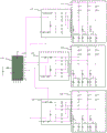
根据本发明的一个方面,本发明提供一种氛围灯开短路诊断电路。请参考图1所示,其为本发明在一个实施例中的氛围灯开短路诊断电路的电路示意图。图1所示的氛围灯开短路诊断电路包括第一检测电路110、第二检测电路120、第三检测电路130和控制单元(未图示),其中,第一检测电路110与对应的第一发光二极管阵列210相连,第二检测电路120与对应的第二发光二极管阵列220相连,第三检测电路130与对应的第三发光二极管阵列230相连。According to one aspect of the present invention, the present invention provides an ambient light open-short circuit diagnostic circuit. Please refer to FIG. 1 , which is a schematic circuit diagram of an open-short circuit diagnosis circuit for an ambient light in an embodiment of the present invention. The ambient light on-short circuit diagnosis circuit shown in FIG. The
请参考图2所示,其为本发明如图1所示的第一检测电路和第一发光二极管阵列的放大示意图。在图1和图2所示的实施例中,第一检测电路110包括第一分压电路112、第二分压电路114、第一二极管单元116和第二二极管单元118。其中,第一二极管单元116包括3个二极管D1、D2和D3,3个二极管D1、D2和D3的阳极分别与对应的第一发光二极管阵列210中的3个检测点a、b和c相连,3个二极管D1、D2和D3的阴极均与第一连接节点A相连。第二二极管单元118包括另外3个二极管D4、D5和D6,3个二极管D4、D5和D6的阴极分别与对应的第一发光二极管阵列210中的3个检测点a、b和c相连,3个二极管D4、D5和D6的阳极均与第二连接节点B相连。第一分压电路112的输入端与第一连接节点A相连,其输出端作为第一诊断节点C。第二分压电路114的输入端与第二连接节点B相连,其输出端作为第二诊断节点D。Please refer to FIG. 2 , which is an enlarged schematic diagram of the first detection circuit and the first LED array shown in FIG. 1 of the present invention. In the embodiment shown in FIG. 1 and FIG. 2 , the
在图1和图2所示的具体实施例中,第一分压电路112包括电阻R2和电阻R1,电阻R2和电阻R1依次串联于第一连接节点A和接地端之间;电阻R2和电阻R1之间的连接节点称为其所在的第一检测电路110的第一诊断节点C。第二分压电路114包括电阻R3、电阻R7和电阻R8,电阻R3连接于第一电源电压VCC和第二连接节点B之间;电阻R8和电阻R7依次串联于第二连接节点B和接地端之间;电阻R7和R8之间的连接节点称为其所在的第一检测电路110的第二诊断节点D。In the specific embodiment shown in FIG. 1 and FIG. 2 , the first
在图1和图2所示的具体实施例中,第一发光二极管阵列210包括3路LED灯211、212和213,以及3路恒流源214、215和216。其中,每路LED灯211、212、213的一端与第一电源电压VCC相连,其另一端经对应的恒流源214、215、216接地;每路LED灯211、212、213和对应的恒流源214、215、216之间的连接节点称为其所在的第一发光二极管阵列210的一个检测点a、b、c。例如,第一路LED灯211的一端与第一电源电压VCC相连,其另一端经第一恒流源214接地,第一路LED灯211和第一恒流源214之间的连接节点称为第一发光二极管阵列210的第一检测点a;第二路LED灯212的一端与第一电源电压VCC相连,其另一端经第二恒流源215接地,第二路LED灯212和第二恒流源215之间的连接节点称为第一发光二极管阵列210的第二检测点b;第三路LED灯213的一端与第一电源电压VCC相连,其另一端经第三恒流源216接地,第三路LED灯213和第三恒流源216之间的连接节点称为第一发光二极管阵列210的第三检测点c。In the specific embodiment shown in FIG. 1 and FIG. 2 , the
在图1和图2所示的具体实施例中,第一路LED灯211包括依次串联的两个发光二极管LED1和LED4;第二路LED灯212包括依次串联的两个发光二极管LED2和LED5;第三路LED灯213包括依次串联的两个发光二极管LED3和LED6。在其他实施例中,每路LED灯211、212、213包括的发光二极管还可以为1个、3个、4个或更多个,也就是说,每路LED灯211、212、213包括依次串联的n个发光二极管,其中,n为正整数。In the specific embodiment shown in FIG. 1 and FIG. 2, the
在图1和图2所示的实施例中,第一恒流源214包括电阻R4、电阻R9、电阻R10、三极管Q1和三极管Q4。其中,三极管Q1的第一连接端经电阻R4与第二电源电压VDD相连,其第二连接端经电阻R9接地,其控制端与其第一连接端相连;三极管Q4的第一连接端与第一恒流源214对应的检测点a相连,其第二连接端经电阻R10接地,其控制端与三极管Q1的控制端相连。在图1和图2所示的具体实施例中,三极管Q1为NPN型三极管,三极管Q1的第一连接端、第二连接端和控制端分别为NPN型三极管的集电极、射极和基极;三极管Q4为NPN型三极管,三极管Q4的第一连接端、第二连接端和控制端分别为NPN型三极管的集电极、射极和基极。In the embodiment shown in FIG. 1 and FIG. 2 , the first constant
在图1所示的实施例中,第二恒流源215与第一恒流源214的电路结构一致,第二恒流源215包括电阻R5、电阻R11、电阻R12、三极管Q2和三极管Q5。其中,三极管Q2的第一连接端经电阻R5与第二电源电压VDD相连,其第二连接端经电阻R11接地,其控制端与其第一连接端相连;三极管Q5的第一连接端与第二恒流源215对应的检测点b相连,其第二连接端经电阻R12接地,其控制端与三极管Q2的控制端相连。在图1所示的具体实施例中,三极管Q2为NPN型三极管,三极管Q2的第一连接端、第二连接端和控制端分别为NPN型三极管的集电极、射极和基极;三极管Q5为NPN型三极管,三极管Q5的第一连接端、第二连接端和控制端分别为NPN型三极管的集电极、射极和基极。In the embodiment shown in FIG. 1 , the second constant
在图1所示的实施例中,第三恒流源216与第一恒流源214的电路结构一致,第三恒流源216包括电阻R6、电阻R13、电阻R14、三极管Q3和三极管Q6。其中,三极管Q3的第一连接端经电阻R6与第二电源电压VDD相连,其第二连接端经电阻R13接地,其控制端与其第一连接端相连;三极管Q6的第一连接端与第三恒流源216对应的检测点c相连,其第二连接端经电阻R14接地,其控制端与三极管Q3的控制端相连。在图1所示的具体实施例中,三极管Q3为NPN型三极管,三极管Q3的第一连接端、第二连接端和控制端分别为NPN型三极管的集电极、射极和基极;三极管Q6为NPN型三极管,三极管Q6的第一连接端、第二连接端和控制端分别为NPN型三极管的集电极、射极和基极。In the embodiment shown in FIG. 1 , the third constant
需要特别说明的是,第二检测电路120和第三检测电路130的电路结构与第一检测电路110的电路结构一致;第二发光二极管阵列220和第三发光二极管阵列230与第一发光二极管阵列210的电路结构一致;第二检测电路120和第二发光二极管阵列220的电路连接关系与第一检测电路110和第一发光二极管阵列210的电路连接关系一致;第三检测电路130和第三发光二极管阵列230的电路连接关系与第一检测电路110和第一发光二极管阵列210的电路连接关系一致;具体请参见上述对第一检测电路110和第一发光二极管阵列210的描述,故在此不再赘述。It should be noted that the circuit structure of the
控制单元(例如,MCU)通过采样每个检测电路110、120、130的第一诊断节点C和第二诊断节点D的电压,并基于第一诊断节点C和第二诊断节点D的电压诊断对应的发光二极管阵列210、220、230的开短路。在图1所示的实施例中,第一发光二极管阵列210、第二发光二极管阵列220和第三发光二极管阵列230组成RGB,例如,第一发光二极管阵列210为红光发光二极管阵列;第二发光二极管阵列220为绿光发光二极管阵列;第三发光二极管阵列230为蓝光发光二极管阵列。The control unit (for example, MCU) samples the voltage of the first diagnosis node C and the second diagnosis node D of each
图1所示的氛围灯开短路诊断电路还包括多路复用开关140,多路复用开关140将每个检测电路110、120、130的第一诊断节点C和第二诊断节点D分时与同一个模数转换器(未图示)的输入接口Vadc相连;控制单元通过该模数转换器(未图示)和多路复用开关140,逐一采样每个检测电路110、120、130的第一诊断节点C和第二诊断节点D的电压。请参考图3所示,其为本发明如图1所示的多路复用开关的放大示意图。如图1和图3所示,多路复用开关140的输入接口S0和S1分别与第一检测电路110的第一诊断节点C和第二诊断节点D相连;其输入接口S2和接口S3分别与第二检测电路120的第一诊断节点C和第二诊断节点D相连;其输入接口S4和接口S5分别与第三检测电路130的第一诊断节点C和第二诊断节点D相连;其电源接口VDD与第二电源电压VDD;其输出接口D依次经分压电阻R43和R44接地,模数转换器(未图示)的输入接口Vadc与分压电阻R43和R44之间的连接节点相连。The ambient light on-short circuit diagnostic circuit shown in FIG. 1 further includes a
以下具体介绍图1所示的氛围灯开短路诊断电路的设计原理。The design principle of the open-short-circuit diagnostic circuit for the ambient light shown in FIG. 1 will be introduced in detail below.
一、硬件原理,以第一检测电路110和第一发光二极管阵列210为例。1. Hardware principle, taking the
1、第一发光二极管阵列210在正常工作情况下,第一电源电压VCC(即输入电压VCC)经过第一发光二极管阵列210到恒流源214、215和216,二极管D1、D2、D3共阴极,阴极电压由三路阳极电压中的最大电压值决定,此时D1、D2、D3阴极的压降(或电压)为最高电压减去二极管的压差;1. When the first light-emitting
2、同时二极管D4、D5、D6的阳极电压由三路阴极电压中的最小电压值决定,二极管D4、D5、D6的阳极通过电阻R3上拉至第一电源电压VCC,保证阳极电压是阴极电压加上一个二极管的压差;2. At the same time, the anode voltages of diodes D4, D5, and D6 are determined by the minimum voltage value among the three cathode voltages. The anodes of diodes D4, D5, and D6 are pulled up to the first power supply voltage VCC through resistor R3 to ensure that the anode voltage is the cathode voltage Add a diode dropout;
3、经过共阳极和共阴极二极管后,采取电阻分压的方式来到Tmux1308-Q1的通道,进行轮询ADC轮询采样;3. After passing through the common anode and common cathode diodes, adopt the method of resistive voltage division to come to the channel of Tmux1308-Q1, and perform polling ADC polling sampling;
4、当第一发光二极管阵列210出现短路时,三路电压中最高电压会被抬高一个LED的电压,经过二极管、电阻分压以后给模数转换器ADC采样,会检测到第一诊断节点C的电压抬高,上报短路;4. When the first light-emitting
5、当第一发光二极管阵列210出现断路时,三路电压中最低电压出现在故障那路,D4、D5、D6的阳极电压相比正常工作会被明显拉低,会检测到第二诊断节点D的电压被明显拉低,上报断路。5. When the first light-emitting
二、工作原理2. Working principle
1、控制单元将初次采样的每个检测电路110、120、130的第一诊断节点C的电压和第二诊断节点D的电压的差值作为诊断参考电压Vadc1存储于存储器中,将实时采样的每个检测电路110、120、130的第一诊断节点C的电压和第二诊断节点D的电压的差值作为诊断检测电压Vadc2,并计算诊断检测电压Vadc2与对应的诊断参考电压Vadc1的差值;1. The control unit stores the difference between the voltage of the first diagnostic node C and the voltage of the second diagnostic node D of each
2、在诊断检测电压Vadc2与对应的诊断参考电压Vadc1的差值位于第一预定波动范围内时,则判定对应的发光二极管阵列210、220、230没有发生开路或短路故障;2. When the difference between the diagnostic detection voltage Vadc2 and the corresponding diagnostic reference voltage Vadc1 is within the first predetermined fluctuation range, it is determined that the corresponding light-emitting
3、在诊断检测电压Vadc2与对应的诊断参考电压Vadc1的差值位于第一预定波动范围外的第二预定波动范围内时,则判定对应的发光二极管阵列210、220、230发生开路故障;3. When the difference between the diagnostic detection voltage Vadc2 and the corresponding diagnostic reference voltage Vadc1 is within the second predetermined fluctuation range outside the first predetermined fluctuation range, it is determined that the corresponding
4、在诊断检测电压Vadc2与对应的诊断参考电压Vadc1的差值位于第一预定波动范围外的第三预定波动范围内时,则判定对应的发光二极管阵列210、220、230发生短路故障;4. When the difference between the diagnostic detection voltage Vadc2 and the corresponding diagnostic reference voltage Vadc1 is within the third predetermined fluctuation range outside the first predetermined fluctuation range, it is determined that a short-circuit fault occurs in the corresponding
5、在开短路诊断期间,控制单元还将初次采样的每个发光二极管阵列210、220、230的第一电源电压VCC作为参考电源电压VCC1存储于存储器中,将实时采样的每个发光二极管阵列210、220、230的第一电源电压VCC作为检测电源电压VCC2,在检测电源电压VCC2与参考电源电压VCC1的差值在第四预定波动范围内时,才对对应的发光二极管阵列210、220、230进行开短路诊断。5. During open-short circuit diagnosis, the control unit also stores the first power supply voltage VCC of each
在一个优选的实施例中,对采样(例如,初次采样或实时采样)的第一诊断节点C的电压、第二诊断节点D的电压以及第一电源电压VCC进行延时和滤波处理。In a preferred embodiment, the sampled (for example, initial sampling or real-time sampling) voltage of the first diagnostic node C, voltage of the second diagnostic node D and the first power supply voltage VCC are delayed and filtered.
需要说明的是,在图1所示的实施例中,检测电路110、120、130为3个,发光二极管阵列为三个,图1所示的氛围灯开短路诊断电路可对RGB进行开短路诊断。在其他实施例中,检测电路可以为1个、2个、4个或更多个,对应的发光二极管阵列也可以为1个、2个、4个或更多个,对应的氛围灯开短路诊断电路可以对1个、2个、4个或更多个发光二极管阵列进行开短路诊断。It should be noted that, in the embodiment shown in FIG. 1 , there are three
也可以说,本发明提供一种氛围灯开短路诊断电路,其包括控制单元以及一个或多个检测电路(例如,检测电路110、120、130),其中,每个检测电路(例如,检测电路110、120、130),均包括第一分压电路112、第二分压电路114、第一二极管单元116和第二二极管单元118,第一二极管单元116包括m个二极管(例如,二极管D1、D2、D3),该m个二极管(例如,二极管D1、D2、D3)的阳极分别与对应的一个发光二极管阵列(例如,发光二极管阵列210、220、230)中的m个检测点(例如,检测点a、b、c)相连,该m个二极管(例如,二极管D1、D2、D3)的阴极均与第一连接节点A相连;第二二极管单元118包括另外m个二极管(例如,二极管D4、D5、D6),另外m个二极管(例如,二极管D4、D5、D6)的阴极分别与对应的发光二极管阵列110中的m个检测点(例如,检测点a、b、c)相连,另外m个二极管(例如,二极管D4、D5、D6)的阳极均与第二连接节点B相连;第一分压电路112的输入端与第一连接节点A相连,其输出端作为其所在的检测电路110的第一诊断节点C;第二分压电路114的输入端与第二连接节点B相连,其输出端作为其所在的检测电路的第二诊断节点D;控制单元通过采样每个检测电路(例如,检测电路110、120、130)的第一诊断节点C和第二诊断节点D的电压,并基于第一诊断节点C和第二诊断节点D的电压诊断对应的发光二极管阵列(例如,发光二极管阵列210、220、230)的开短路故障,其中,m为正整数。It can also be said that the present invention provides an ambient light on-short circuit diagnosis circuit, which includes a control unit and one or more detection circuits (for example,
对应的,每个发光二极管阵列(例如,发光二极管阵列210、220、230)包括m路LED灯(例如,每路LED灯211、212、213)和m个恒流源(例如,恒流源214、215、216),每路LED灯(例如,每路LED灯211、212、213)的一端与其所在的发光二极管阵列(例如,发光二极管阵列210、220、230)的电源端电压VCC相连,其另一端经对应的恒流源(例如,恒流源214、215、216)接地;每路LED灯(例如,每路LED灯211、212、213)和对应的恒流源(例如,恒流源214、215、216)之间的连接节点称为其所在的发光二极管阵列(例如,发光二极管阵列210、220、230)中的一个检测点(例如,检测点a、b、c)。Correspondingly, each light emitting diode array (for example, light emitting
根据本发明的另一个方面,本发明提供一种基于图1所示的氛围灯开短路诊断电路的开短路诊断方法,请参考图4所示,其为本发明在一个实施例中的氛围灯开短路诊断电路的开短路诊断方法的流程图。图4所示的氛围灯开短路诊断电路的开短路诊断方法包括如下步骤。According to another aspect of the present invention, the present invention provides an open-short circuit diagnosis method based on the ambient light open-short circuit diagnosis circuit shown in FIG. 1 , please refer to FIG. 4 , which is the ambient light in an embodiment of the present invention. A flowchart of an open-short circuit diagnosis method of an open-short circuit diagnosis circuit. The open-short circuit diagnosis method of the ambient light open-short circuit diagnosis circuit shown in FIG. 4 includes the following steps.
步骤410、控制单元将初次采样的每个检测电路110、120、130的第一诊断节点C的电压和第二诊断节点D的电压的差值作为诊断参考电压Vadc1存储于存储器中;
步骤420、控制单元将实时采样的每个检测电路110、120、130的第一诊断节点C的电压和第二诊断节点D的电压的差值作为诊断检测电压Vadc2,并计算诊断检测电压Vadc2与对应的诊断参考电压Vadc1的差值;
步骤430、在诊断检测电压Vadc2与对应的诊断参考电压Vadc1的差值位于第一预定波动范围内时,则判定对应的发光二极管阵列210、220、230没有发生开路或短路故障;
步骤440、在诊断检测电压Vadc2与对应的诊断参考电压Vadc1的差值位于第一预定波动范围外的第二预定波动范围内时,则判定对应的发光二极管阵列210、220、230发生开路故障;
步骤450、在诊断检测电压Vadc2与对应的诊断参考电压Vadc1的差值位于第一预定波动范围外的第三预定波动范围内时,则判定对应的发光二极管阵列210、220、230发生短路故障。
在一个实施例中,在开短路诊断期间,控制单元还将初次采样的每个发光二极管阵列210、220、230的第一电源电压VCC作为参考电源电压VCC1存储于存储器中,将实时采样的每个发光二极管阵列210、220、230的第一电源电压VCC作为检测电源电压VCC2,在检测电源电压VCC2与参考电源电压VCC1的差值在第四预定波动范围内时,才对对应的发光二极管阵列210、220、230进行开短路诊断。In one embodiment, during the open-short circuit diagnosis period, the control unit also stores the first power supply voltage VCC of each
在一个优选的实施例中,对采样(例如,初次采样或实时采样)的第一诊断节点C的电压、第二诊断节点D的电压以及第一电源电压VCC进行延时和滤波处理。In a preferred embodiment, the sampled (for example, initial sampling or real-time sampling) voltage of the first diagnostic node C, voltage of the second diagnostic node D and the first power supply voltage VCC are delayed and filtered.
综上所述,本发明利用二极管的正向导通特性,当RGB发生开路和短路时ADC检测的电压会发生变化;本发明还采用多路复用开关轮询采样,判断ADC采样值前后变化做出诊断,从而不仅能够可靠的区分RGB的开路和短路故障,而且还减少了MCU外设的使用,简单可靠。In summary, the present invention utilizes the forward conduction characteristic of the diode, and the voltage detected by the ADC will change when the RGB is open-circuited or short-circuited; Diagnosis, so that not only can reliably distinguish RGB open circuit and short circuit faults, but also reduce the use of MCU peripherals, simple and reliable.
需要指出的是,熟悉该领域的技术人员对本发明的具体实施方式所做的任何改动均不脱离本发明的权利要求书的范围。相应地,本发明的权利要求的范围也并不仅仅局限于前述具体实施方式。It should be pointed out that any changes made by those skilled in the art to the specific embodiments of the present invention will not depart from the scope of the claims of the present invention. Accordingly, the scope of the claims of the present invention is not limited only to the foregoing specific embodiments.
Claims (13)
Priority Applications (1)
| Application Number | Priority Date | Filing Date | Title |
|---|---|---|---|
| CN202310519747.7A CN116400262B (en) | 2023-05-09 | 2023-05-09 | A reliable open/short circuit diagnostic circuit for ambient lights and its diagnostic method |
Applications Claiming Priority (1)
| Application Number | Priority Date | Filing Date | Title |
|---|---|---|---|
| CN202310519747.7A CN116400262B (en) | 2023-05-09 | 2023-05-09 | A reliable open/short circuit diagnostic circuit for ambient lights and its diagnostic method |
Publications (2)
| Publication Number | Publication Date |
|---|---|
| CN116400262A true CN116400262A (en) | 2023-07-07 |
| CN116400262B CN116400262B (en) | 2026-01-30 |
Family
ID=87014360
Family Applications (1)
| Application Number | Title | Priority Date | Filing Date |
|---|---|---|---|
| CN202310519747.7A Active CN116400262B (en) | 2023-05-09 | 2023-05-09 | A reliable open/short circuit diagnostic circuit for ambient lights and its diagnostic method |
Country Status (1)
| Country | Link |
|---|---|
| CN (1) | CN116400262B (en) |
Citations (10)
| Publication number | Priority date | Publication date | Assignee | Title |
|---|---|---|---|---|
| US6133724A (en) * | 1998-06-29 | 2000-10-17 | E. O. Schweitzer Manufacturing Co. | Remote light indication fault indicator with a timed reset circuit and a manual reset circuit |
| US20120181931A1 (en) * | 2011-01-13 | 2012-07-19 | Rohm Co., Ltd. | Led short-circuit detection circuit, led drive device, led lighting device, and vehicle |
| WO2013150732A1 (en) * | 2012-04-04 | 2013-10-10 | シャープ株式会社 | Esd test inspection device and esd test inspection method |
| CN104111399A (en) * | 2013-04-22 | 2014-10-22 | 上海航天汽车机电股份有限公司 | Vehicle electronic control unit ground connection and ground pressure difference detection circuit |
| US20160343526A1 (en) * | 2015-05-21 | 2016-11-24 | Asco Power Technologies, L.P. | Short Circuit Detection Circuit |
| CN205786825U (en) * | 2016-06-15 | 2016-12-07 | 深圳拓邦股份有限公司 | Isolation voltage testing circuit |
| CN212412742U (en) * | 2020-03-17 | 2021-01-26 | 中山市格瑞斯电子有限公司 | Open circuit protection and overheating protection circuit applied to power indicator lamp |
| US20220049669A1 (en) * | 2019-03-13 | 2022-02-17 | Hitachi Astemo, Ltd. | Load Drive Device, Engine System |
| CN218412858U (en) * | 2022-09-08 | 2023-01-31 | 广州导远电子科技有限公司 | Antenna state detection circuit and electronic equipment |
| CN219842537U (en) * | 2023-05-09 | 2023-10-17 | 科博达技术股份有限公司 | Reliable atmosphere lamp open-short circuit diagnosis circuit |
-
2023
- 2023-05-09 CN CN202310519747.7A patent/CN116400262B/en active Active
Patent Citations (10)
| Publication number | Priority date | Publication date | Assignee | Title |
|---|---|---|---|---|
| US6133724A (en) * | 1998-06-29 | 2000-10-17 | E. O. Schweitzer Manufacturing Co. | Remote light indication fault indicator with a timed reset circuit and a manual reset circuit |
| US20120181931A1 (en) * | 2011-01-13 | 2012-07-19 | Rohm Co., Ltd. | Led short-circuit detection circuit, led drive device, led lighting device, and vehicle |
| WO2013150732A1 (en) * | 2012-04-04 | 2013-10-10 | シャープ株式会社 | Esd test inspection device and esd test inspection method |
| CN104111399A (en) * | 2013-04-22 | 2014-10-22 | 上海航天汽车机电股份有限公司 | Vehicle electronic control unit ground connection and ground pressure difference detection circuit |
| US20160343526A1 (en) * | 2015-05-21 | 2016-11-24 | Asco Power Technologies, L.P. | Short Circuit Detection Circuit |
| CN205786825U (en) * | 2016-06-15 | 2016-12-07 | 深圳拓邦股份有限公司 | Isolation voltage testing circuit |
| US20220049669A1 (en) * | 2019-03-13 | 2022-02-17 | Hitachi Astemo, Ltd. | Load Drive Device, Engine System |
| CN212412742U (en) * | 2020-03-17 | 2021-01-26 | 中山市格瑞斯电子有限公司 | Open circuit protection and overheating protection circuit applied to power indicator lamp |
| CN218412858U (en) * | 2022-09-08 | 2023-01-31 | 广州导远电子科技有限公司 | Antenna state detection circuit and electronic equipment |
| CN219842537U (en) * | 2023-05-09 | 2023-10-17 | 科博达技术股份有限公司 | Reliable atmosphere lamp open-short circuit diagnosis circuit |
Also Published As
| Publication number | Publication date |
|---|---|
| CN116400262B (en) | 2026-01-30 |
Similar Documents
| Publication | Publication Date | Title |
|---|---|---|
| CN219842537U (en) | Reliable atmosphere lamp open-short circuit diagnosis circuit | |
| CN116400262A (en) | A reliable open-short-circuit diagnosis circuit and its open-short-circuit diagnosis method for ambient light | |
| CN207817172U (en) | A battery sampling harness detector | |
| CN114867150A (en) | Series-parallel power line pulse signal triggering operation bidirectional colored lamp | |
| CN220673970U (en) | Circuit for controlling indicator lamp according to output voltage and by using single port | |
| CN203772299U (en) | Thru-beam sensor detection device | |
| CN110780238A (en) | Multi-core cable detection device | |
| CN207969010U (en) | Constant current driver circuit for LED | |
| CN219145677U (en) | LED fault detection circuit and lamp | |
| CN100527623C (en) | LED open circuit by-pass circuit | |
| CN209897326U (en) | Novel one-support-two LED driving mode | |
| CN202634851U (en) | Constant-current driving circuit for LEDs in system test | |
| CN206821047U (en) | The dummy load circuit of LED controller for daytime running light | |
| CN102854436B (en) | A kind of power polarity detection circuit | |
| CN211603518U (en) | Multi-core cable detection device | |
| CN108680821B (en) | A New Tooling Circuit Applied in BMS Inspection | |
| CN103781220A (en) | Light emitting diode control circuit | |
| CN223526492U (en) | IC pin conductivity test circuit and tester | |
| CN220629617U (en) | LED lamp strip drive circuit suitable for different voltage grades | |
| CN221306149U (en) | Simple electronic diagnosis feedback circuit | |
| CN218956693U (en) | A remote control detection circuit and device | |
| CN223182360U (en) | Constant current drive circuit and vehicle light device | |
| CN221986213U (en) | A monitoring device for controller circuit, air conditioner and control system thereof | |
| CN117612479B (en) | Selection circuit, LED display device and LED lamp strip | |
| CN221782394U (en) | Detection device |
Legal Events
| Date | Code | Title | Description |
|---|---|---|---|
| PB01 | Publication | ||
| PB01 | Publication | ||
| SE01 | Entry into force of request for substantive examination | ||
| SE01 | Entry into force of request for substantive examination | ||
| GR01 | Patent grant |