CN116390675A - Device for fastening a front panel to a drawer side frame - Google Patents
Device for fastening a front panel to a drawer side frame Download PDFInfo
- Publication number
- CN116390675A CN116390675A CN202180065848.0A CN202180065848A CN116390675A CN 116390675 A CN116390675 A CN 116390675A CN 202180065848 A CN202180065848 A CN 202180065848A CN 116390675 A CN116390675 A CN 116390675A
- Authority
- CN
- China
- Prior art keywords
- front panel
- side frame
- retaining plate
- bracket
- adapter
- Prior art date
- Legal status (The legal status is an assumption and is not a legal conclusion. Google has not performed a legal analysis and makes no representation as to the accuracy of the status listed.)
- Pending
Links
Images


Classifications
-
- A—HUMAN NECESSITIES
- A47—FURNITURE; DOMESTIC ARTICLES OR APPLIANCES; COFFEE MILLS; SPICE MILLS; SUCTION CLEANERS IN GENERAL
- A47B—TABLES; DESKS; OFFICE FURNITURE; CABINETS; DRAWERS; GENERAL DETAILS OF FURNITURE
- A47B88/00—Drawers for tables, cabinets or like furniture; Guides for drawers
- A47B88/90—Constructional details of drawers
- A47B88/944—Drawers characterised by the front panel
- A47B88/95—Drawers characterised by the front panel characterised by connection means for the front panel
- A47B88/956—Drawers characterised by the front panel characterised by connection means for the front panel for enabling adjustment of the front panel
-
- A—HUMAN NECESSITIES
- A47—FURNITURE; DOMESTIC ARTICLES OR APPLIANCES; COFFEE MILLS; SPICE MILLS; SUCTION CLEANERS IN GENERAL
- A47B—TABLES; DESKS; OFFICE FURNITURE; CABINETS; DRAWERS; GENERAL DETAILS OF FURNITURE
- A47B88/00—Drawers for tables, cabinets or like furniture; Guides for drawers
- A47B88/90—Constructional details of drawers
- A47B88/944—Drawers characterised by the front panel
- A47B88/95—Drawers characterised by the front panel characterised by connection means for the front panel
- A47B2088/951—Drawers characterised by the front panel characterised by connection means for the front panel having male and female interlocking parts
-
- A—HUMAN NECESSITIES
- A47—FURNITURE; DOMESTIC ARTICLES OR APPLIANCES; COFFEE MILLS; SPICE MILLS; SUCTION CLEANERS IN GENERAL
- A47B—TABLES; DESKS; OFFICE FURNITURE; CABINETS; DRAWERS; GENERAL DETAILS OF FURNITURE
- A47B88/00—Drawers for tables, cabinets or like furniture; Guides for drawers
- A47B88/90—Constructional details of drawers
- A47B88/944—Drawers characterised by the front panel
- A47B88/95—Drawers characterised by the front panel characterised by connection means for the front panel
- A47B2088/954—Drawers characterised by the front panel characterised by connection means for the front panel fastening the front panel by a sprung bolt, latch or lock-bolt
Landscapes
- Drawers Of Furniture (AREA)
Abstract
The invention relates to a device (6) for fastening a front panel (2) to a side frame (3) of a drawer (1), comprising a bracket (8) which can be fastened to the front panel (2) and an adapter (10, 11) which can be fastened to the side frame (3), on which the bracket (8) is adjustably held, wherein the bracket (8) can be inserted through a holding plate (20) into a receptacle (14) on the adapter (10, 11) and can be fastened by means of a latching element (30), wherein the latching element (30, 30') takes the form of a flexible spring which latches onto a projection (21) on the holding plate (20) by means of a leg (31). Thereby, the front panel (2) can be effectively mounted on the side frame (3) by a simple method.
Description
The invention relates to a device for fastening a front panel to a drawer side frame, comprising a bracket which can be fastened to the front panel and an adapter which can be fastened to the side frame, wherein the bracket is adjustably held on the adapter, can be inserted into a receptacle on the adapter by means of a holding plate and can be fastened by means of a latch.
DE202010002617U1 discloses a fastening system for fixing a front panel to drawer side panels, wherein an engagement member can be inserted into a side frame in which an annular spring member is arranged. The spring element can be tensioned by a double-arm fastening lever in order to fix the hook of the engagement element in the side frame. Although this allows for efficient assembly, the retention force of the spring element is limited. Furthermore, the tightening force is not well adjusted with the tightening rod due to the position of the hooks.
The object of the invention is therefore to create a compact device for fastening a front panel, which provides a high clamping force.
This object is achieved by a device having the features of claim 1.
The device according to the invention comprises a bracket which can be fastened to the front panel and an adapter which can be fastened to the side frame, wherein the bracket can be inserted through a retaining plate into a receptacle on the adapter and can be fastened there by means of a latch. According to the invention, the latch comprises at least one flexible spring which engages behind a projection on the retaining plate by means of at least one leg. Thus, by inserting the retaining plate, the fixing may be performed by latching the at least one leg after the protrusion, thereby omitting further assembly steps, such as tensioning the ring. This facilitates assembly and furthermore can provide a high holding force by the latch.
Preferably, the retaining plate is secured to the latch by clamping. This avoids rattling noise and ensures that the bracket is secured to the adapter with a strong fit.
In a preferred embodiment, the at least one flexible spring is designed as a leaf spring. The spring may also include two legs that clip to the retaining plate on opposite sides. This ensures that the retaining plate is centered between the two legs of the spring. For particularly high clamping forces, the at least one projection on the holding plate may comprise a running ramp which is inclined to the insertion direction and which abuts against one end of each leg of the flexible spring. The legs of the springs may be arranged at an angle on the running ramp, for example at an angle between 60 ° and 120 °, in particular between 70 ° and 110 °, so that when the bracket is subjected to a tensile force, the legs are subjected to compression and the bracket is prevented from being pulled apart. On the other hand, the pivoting of the legs during assembly can be performed smoothly, which can be achieved by angular alignment of the legs with the insertion direction, for example if the legs are inclined to the insertion direction at an angle between 10 ° and 40 °. In this case, the leaf spring can be designed as a bent-over part, wherein the two legs of the U each form a bent-back leg for the fastening projection, so that the two legs with their edges are aligned with the bottom of the spring.
The device preferably comprises a release lever on the adapter, which release lever is pivotally mounted and by means of which the at least one bendable spring can be pulled away from the holding plate. The release lever can thus close the opening to the protruding receptacle in the locked position. For opening, the release lever is then pivoted, preferably about a vertical axis in the mounted position, wherein the at least one bendable spring is preferably fixed to the release lever and thereby moves together with the release lever to be pulled away from the protrusion.
The adapter is preferably made of several parts, including a stationary housing that can be fixed to the side frame and a slider slidably mounted in the housing. The housing may be inserted in the fixed part of the side frame and is preferably U-shaped in order to receive the slider in the central area. The retaining plate of the bracket is preferably secured to a slider on which the receptacle is formed. The slide is preferably displaceable relative to the housing by means for height adjustment. For this purpose, corresponding guides are provided between the slide and the housing, which can be adjusted by means of eccentrics, screws, worms or other rotatable and linear adjusting devices.
For the lateral adjustment in the horizontal direction perpendicular to the insertion direction, the holding plate is preferably held with play in the receptacle of the adapter, in particular in the slide of the adapter, so that the position of the holding plate relative to the adapter, in particular the slide, can be adjusted by a lateral adjuster, such as an eccentric, a worm, a screw or other mechanical adjustment.
The bracket with the retaining plate can be designed as one or more parts, wherein the retaining plate is designed to transmit high retaining forces.
In a further embodiment, two latches are retained on the release lever, both latching on the protrusions of the retaining plate. In order to achieve a higher holding force, both latching elements can be designed as leaf springs, which latch with at least two, preferably four, legs to the projections of the holding plate. The latch member may be annular and coupled to a fixed protrusion on the release lever.
The device is used in particular on drawers for fixing a front panel to side frames, whereby the front panel is fixed to both side frames. In case the front panel is high, a plurality of means for fixation may also be provided, so that the upper means may optionally be installed without height adjustment, as this is achieved by the lower means.
The invention is explained in more detail below by way of examples with reference to the accompanying drawings. The following is shown:
FIG.1 is a perspective view of a drawer according to the present invention;
FIG.2 is a detailed view of the drawer of FIG.1 at the connection area of the front panel to the side frame;
figures 3A and 3B are two views of an apparatus for connecting a front panel to a side frame during assembly;
FIGS. 4A and 4B are two views of the device of FIG.3 in a released position;
FIGS. 5A and 5B are two views of the device of FIG.3 in a disassembled position;
FIG.6 is an exploded view of an apparatus for attaching a front panel to a side frame;
7A-7C are various views of the device of FIG.6 during assembly, toward the latch;
8A-8C are multiple views of the device of FIG.6 in different adjustment positions;
figures 9A-9C are multiple views of the device of figure 6 in laterally different adjustment positions;
FIG.10 is a perspective view of a second apparatus for attaching a front panel to a side frame;
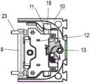
FIG.11 is an exploded view of the device of FIG. 10;
FIG.12 is a perspective view of the device of FIG.10 in an unlocked position;
FIG.13 is an exploded view of a modified apparatus for attaching a front panel to a side frame;
FIGS. 14A-14C are multiple views of a bracket mounted on the housing of FIG. 13;
FIGS. 15A and 15B are two views of a bracket of the device of FIG. 13;
FIGS. 16A and 16B are two views of a modified bracket of the front panel fixation device;
figures 17A and 17B are two views of a modified bracket of the device for fixing a front panel, and
fig.18A and 18B are two views of another bracket of the apparatus for fixing a front panel.
In particular for furniture, comprises a drawer 1 comprising a front panel 2 held on two side frames 3. The side frames 3 connect the front panel 2 to the rear wall 4 and hold the base 5. A device 6 for fixing the front panel 2 to the side frames 3 and another device 7 for fixing the front panel 2 according to the present invention are provided on each side frame 3.
As shown in fig.2, the device 6 comprises an adapter with a housing 10, which is fixed to the side frame 3, for example by being inserted into a core receptacle on the side frame 3. The bracket 8 is fixed to the adapter and the front panel 2 is fixed to the bracket 8. A further device 7 is arranged above the device 6 and comprises a modified housing 9 fixed to the side frame 3.
Fig.3A shows the device 6 without the side frames 3 and the front panel 2. The bracket 8 comprises a retaining plate 20 comprising a widening projection 21 on its side facing the adapter. The lateral adjuster 22 is provided on the holding plate 20. The bracket 8 is made of a metal plate bent into a U shape, and the holding plate 20 is integrally molded therewith. However, the support 8 can also be made of plastic or have a different geometry. The brackets 8 are provided with openings, each of which is passed through a screw 23, in order to fix the front panel 2 to the brackets 8, for example using pins or threaded sleeves.
However, the bracket 8 and the retaining plate 20 may also be produced as two separate parts, which are connected by form fit, force fit and/or material connection before or during assembly.
The adapter comprises a housing 10 which is fixable to the side frame 3 and which is substantially U-shaped and in which a slide 11 is displaceably held. The slide 11 is provided with a release lever 12 which in the closed position closes the receptacle 14 for the insertion of the retaining plate 20. The release lever 12 may be latched to the slider 11 by a latching means, such as a latching hook.
To mount the front panel 2 on the side frame 3, the bracket 8 with the front panel (not shown) is moved to the adapter so that the retaining plate 20 is inserted into the receptacle 14 and latched thereto. After locking, the front panel 2 is fixed to the side frames 3 and can now still be adjusted in the height and/or transverse horizontal direction. For this purpose, a height adjuster 13 is provided on the housing 10 so that the slider 11 can be moved in the vertical direction on the housing 10.
In fig.4A and 4B, the release lever 12 has been pivoted from the locked position shown in fig.3B to the unlocked position. By pivoting the release lever 12, the retaining plate 20 and the projection 21 have been unlocked and can now be pulled out of the receptacle 14 again. The release lever 12 has been pivoted about an axis vertical in the assembled position. In fig.5A and 5B, the bracket 8 and the retaining plate 20 have been pulled out of the receptacle 14. It can be seen that the latch 30 is held on the release lever 12 in the form of a flexible spring.
Fig.6 shows the device 6 in detail. The bracket 8 comprises an opening 24 in the plate-like holding plate 20, in which a lateral adjuster 22 is inserted. The lateral adjuster 22 may be a screw, worm screw or other adjuster for adjusting the retaining plate 20 in a lateral direction relative to the slider 11. The projection 21 comprises, on the rear face facing the bracket 8, a walking aid slope 25 for locking during assembly.
A receptacle 14 for inserting the retaining plate 20 is formed on the slide 11, which is essentially bowl-shaped and in which the retaining plate 20 is arranged with play. In order to form an insertion opening for the holding plate 20, a bracket 15 is provided which is inserted through the edge side legs and is mounted in a slot 16 on the slide 11. An opening 17 is formed in the bracket 15 through which a tool can access the lateral adjustment member 22.
A receiving seat 18 for guiding the slider 11 is formed on the housing 10, into which a guide plate of the slider 11 can be inserted so as to guide the slider 11 on the housing 10 in a vertical direction. The housing 10 is U-shaped and includes a receptacle 18 on each of the two legs. The height adjuster 13 is also provided on the housing 10, in which an adjusting member 35 is inserted so as to be able to rotate the height adjuster 13. The height adjuster 13 is designed here as an eccentric which abuts against an eccentric receptacle 36 on the slide 11, so that the slide 11 can be displaced in the vertical direction along the housing 10 by rotating the height adjuster 13. In addition to the eccentric, a screw, worm or other adjustment may be provided.
The release lever 12 is pivotally mounted on the slide 11, for which purpose the release lever 12 comprises two shafts 19 which engage with bearing receptacles on the slide 11. In the installed position, the release lever 12 is rotatable about a substantially vertical axis.
The latch 30 is secured to the release lever 12 on at least one receptacle, such as by clamping or latching. The latch 30 is designed as a flexible spring, in particular a U-shaped leaf spring, comprising a base and two legs 31, wherein a bend is formed on each leg 31 to form a leg 31 for the latch-holding plate 20. Each leg 31 has an end 32 directed towards the base of the spring. The design as an integral leaf spring results in a simple assembly on the release lever 12 and a secure fixing of the retaining plate 20.
Fig.7A to 7C show the mounting of the retaining plate 20 on the latch 30. The holding plate 20 is inserted into the receptacle 14 on the slide 11 in an insertion direction which is perpendicular to the plane of the front panel 2 in the mounted position. The widened protrusions 21 of the retaining plate 20 push the two legs 31 of the latch 30 outwards as shown in fig. 7B. The projection 21 slides between the two legs 31 which are bent outwards. With further insertion movement the projection 21 moves behind the leg 31 and locks there. The legs 31 now again spread inwardly towards the retaining plate 20 and with one end 32 abutting the walking ramp 25 of the projection 21. The angle between the leg 31 and the walking ramp 25 is preferably between 60 ° and 120 °, so that in the case of a tensile force on the retaining plate 20, the leg 31 is subjected to a compressive force and can thus provide a high retaining force. The protrusions 21 may include top and bottom sipes in the areas of contact with the legs 31, which additionally increases retention. Centering in the height direction is achieved by positioning the retaining plate 20 between the two legs 31. In this example of embodiment, each of the two legs 31 includes a recess for securely receiving the projection 21. Alternatively, in another embodiment, the retaining plate 20 may be locked by only a single leg 31 instead of by two legs 31.
Fig.8A to 8C show the height adjustment of the support 8 on the adapter. The height adjuster 13 is held on the housing 10, which is arranged in the center position of fig. 8A. By rotating the height adjuster 13, the eccentric is rotated along the eccentric receptacle 36, thereby ensuring a linear displacement of the slide 11 in the vertical direction, which is guided by a guide plate on the receptacle 18. In fig.8B, the slider 11 with the release lever 12 is shown in an upper position, while in fig.8C, the slider 11 with the release lever 12 is shown in a lower position. The adjustment can be carried out continuously or in a stepwise locking manner in an adjustment range of, for example, 2mm to 30mm, in particular 3mm to 15 mm.
In fig.9A to 9C, the device 6 is shown in different lateral positions. In fig.9A, the bracket 8 is shown in a central position, wherein the retaining plate 20 is centrally positioned in the receptacle 14 with play on both the left and right sides. The holding plate 20 is moved to the left by the lateral adjuster 22 until it abuts against the wall of the slide 11. This is the maximum left adjustment position. If the lateral adjuster 22 is turned in the opposite direction, the retaining plate 20 abuts the bracket 15, which limits further movement.
In the case of drawers 1, each side frame 3 may be provided with a single means 6 for fixing the front panel 2 to the side frame 3. In the case of a front panel 2 with a greater height, at least one further device 7 may optionally be provided, comprising a housing 9 which can be fixed to the side frame 3. Such a device 7 is shown in fig.10 to 12. The slide 11 is also displaceably held on the housing 9, wherein no height adjustment is provided, unlike in the case of the device 6. The slide 11 is thus displaced along the housing 9 by the guide plate, as described in relation to the device 6, the slide 11 then not being actively moved by the adjusting element. The modified receptacle 14' is provided on the slide 11, in which the retaining plate 20 of the second bracket 8 can be inserted. The support 8 is designed as described above, including a lateral adjuster 22, which in this example of embodiment is not functional. The slider 11 comprises a plurality of ribs in the area against which the protrusions 21 abut to enhance lateral stability. The locking is performed as in the lower device 6. The upper region of the front panel 2 may be secured to the side frames 3 by means of means 7.
Fig.12 shows the release position of the device 7, in which the release lever 12 releases the receptacle 14 'so that the retaining plate 20 can be pulled out of the receptacle 14' on the slide 11.
In the illustrated embodiment, an integral leaf spring is provided as the latch 30.
Fig.13 shows a modified embodiment of the device 6 for securing the front panel 2, wherein a two-piece latch 30' is provided. Each latch 30' is designed as a spring fixed to the release lever 12. Each locking member 30' is curved in a loop, comprising a first leg 31 having an end 32 and a second leg 33 arranged at an angle to each other. The latch 30' is received in the receptacle 14 of the housing 10.
In fig.13, two screws may be mounted on the bracket 8, which screws may be screwed into pins 26, which are inserted into holes in the front panel 2. The bracket 8 comprises a holding plate 20 provided at its end with a projection 21 with a catch 27.
Fig.14A to 14C show the mounting of the bracket 8 on the housing 10 of fig. 13. The latches 30' are respectively pushed to the holding protrusions 34 on the release lever 12. The holding plate 20 is inserted into the receiving seat 14 on the slider 11 in the insertion direction. The widened protrusions 21 of the retaining plate 20 push out the two first legs 31 of the locking member 30', as shown in fig. 14B. In this way, the protrusions 21 slide in a clamping manner between the two first legs 31, which are bent outwards. The two second legs 33 are also contacted and bent by the protrusions 21.
Fig.14C shows the latched position achieved by further insertion action of the projection 21. The first leg 31 is arranged on the rear side of the projection 21 and one end 32 abuts the walking aid slope 25 of the projection 21. The angle between one leg 31 and the walker slope 25 is preferably between 60 deg. and 120 deg.. The two second legs 33 engage in the groove-shaped locking receptacles 27 on the projections 21, respectively, and can thus provide a further holding force. Thus, in the case of a two-piece spring, the shape of the two legs 31 and 33 may be such that each latch 30' has a second lock to ensure safety. In this case, the brackets 8 may each comprise a second latch receptacle 27 in the region of the projection 21.
Fig.15A and 15B show details of the support 8 of the device 6 of fig. 13. The bracket 8 includes a U-shaped bent strap with embossments 80 that cooperate with embossments 28 on the separately manufactured retainer plate 20 to clamp it to the bracket 8. A projection 21 with a catch 27 is provided on the holding plate 20. The projection comprises a walking ramp 25 provided with corrugations in order to be able to lock the leg 31 along the corrugations and to provide a higher holding force.
Fig.16A and 16B show a modified bracket 8', which comprises a strip-shaped body, in particular a cast piece made of plastic or metal, with a slot-shaped receptacle 81 and an opening 82 for the screw 23. One end of the holding plate 20 is inserted into and fixed to the slot-shaped receiving seat 81. For this purpose, the retaining plate 20 may be engaged and frictionally connected to the plate-like body. Alternatively or additionally, an adhesive or material locking connection may also be provided.
The modified bracket 8 "shown in fig.17A and 17B has a slot-shaped receptacle 83 of a band-like body into which one end of the holding plate 20 is inserted. A transverse stop 29 is formed on the retaining plate 20, which limits the insertion depth. The retaining plate 20 may be attached to the ribbon by a force fit or a material fit.
Fig.18A and 18B show an integrated bracket 8 made of a bent steel plate. Two eyelets 84 are formed on the bracket 8 at the holding plate 20, in which screws 23 can be inserted. With embossments 28 between the two perforations 84. The protrusions 21 are formed at the ends of the support web in a manner as illustrated in the previous embodiments.
Marking inventory
1. Drawer with a drawer body
2. Front panel
3. Side frame
4. Rear wall
5. Substrate
6. Device and method for controlling the same
7. Device and method for controlling the same
8. 8', 8' support
9. Outer casing
10. Outer casing
11. Sliding block
12. Release lever
13. Height adjuster 14, 14' receptacle
15. Bracket
16. Slot groove
17. An opening
18. Receiving seat
19. Shaft
20. Retaining plate
21. Protrusions
22. Lateral adjuster 23 screw
24. An opening
25. Walking aid slope
26. Pin
27. Lock catch
28. Embossing
29. Stop block
30 30' latch
31. Leg(s)
32. End portion
33. Second leg
34. Retaining protrusion
35. Adjusting piece
36. Eccentric receiving seat
80. Embossing
81. Slot type receiving seat
82. An opening
83. Slot type receiving seat
84. Eyelet hole
Claims (14)
1. Device (6) for fixing a front panel (2) to a side frame (3) of a drawer (1), having a bracket (8, 8 ') which can be fixed to the front panel (2) and an adapter (10, 11) which can be fixed to the side frame (3), on which the bracket (8, 8 ') is adjustably held, the bracket (8) being insertable into a receptacle (14) on the adapter (10, 11) via a holding plate (20) and being fixed by means of at least one latch (30), the at least one latch (30, 30 ') being designed as a flexible spring which engages behind a projection (21) on the holding plate (20) via at least one leg (31), characterized in that a release lever (12) is pivotably mounted on the adapter (10, 11) which can be used to pull the flexible spring away from the holding plate (20).
2. The device according to claim 1, characterized in that the retaining plate (20) is fastened to the latch (30, 30') in a clamping manner.
3. Device according to claim 1 or 2, characterized in that the bendable spring is designed as a leaf spring.
4. Device according to one of the preceding claims, characterized in that the bendable spring comprises two legs (31) which grip the retaining plate (20) on opposite sides.
5. Device according to one of the preceding claims, characterized in that the at least one projection (21) on the retaining plate (20) comprises a walking ramp (25) oriented obliquely to the insertion direction and abutting one end (32) of the leg (31) of the bendable spring.
6. Device according to one of the preceding claims, characterized in that the release lever (12) closes the opening to the receptacle (14) in the locked position.
7. Device according to one of the preceding claims, characterized in that the bendable spring is fixed to the release lever (12).
8. Device according to one of the preceding claims, characterized in that the adapter comprises a stationary housing (9, 10) which can be fixed to the side frame (3) and a slide (11) which is displaceably mounted in the housing (9, 10).
9. The device according to claim 8, characterized in that the retaining plate (20) is fixed to a slider (11) formed on the receptacle (14, 14').
10. Device according to one of the preceding claims, characterized in that the retaining plate (20) is held in the receptacle (14) of the adapter (10, 11) so as to be adjustable by means of a transverse adjuster (22) in a transverse horizontal direction perpendicular to the insertion direction of the retaining plate (20).
11. Device according to one of the claims, characterized in that the retaining plate (20) is height-adjustable by means of a height adjuster (13) on the adapter (10, 11).
12. Device according to one of the preceding claims, characterized in that two latching elements (30') are held on the release lever (12), which are latched on the projections (21) of the holding plate (20).
13. Device according to claim 12, characterized in that the two latching elements (30') are latched on the projection (21) by means of four legs (31, 33).
14. Drawer having a side frame (3) and a front panel (2), wherein the front panel (2) is fixed to the side frame (3) by means of a device (6) according to one of the preceding claims.
Applications Claiming Priority (3)
| Application Number | Priority Date | Filing Date | Title |
|---|---|---|---|
| DE102020126583.2A DE102020126583A1 (en) | 2020-10-09 | 2020-10-09 | Device for attaching a front panel to a side frame of a drawer |
| DE102020126583.2 | 2020-10-09 | ||
| PCT/EP2021/077352 WO2022073959A1 (en) | 2020-10-09 | 2021-10-05 | Device for fastening a front panel to a side frame of a drawer |
Publications (1)
| Publication Number | Publication Date |
|---|---|
| CN116390675A true CN116390675A (en) | 2023-07-04 |
Family
ID=78085901
Family Applications (1)
| Application Number | Title | Priority Date | Filing Date |
|---|---|---|---|
| CN202180065848.0A Pending CN116390675A (en) | 2020-10-09 | 2021-10-05 | Device for fastening a front panel to a drawer side frame |
Country Status (4)
| Country | Link |
|---|---|
| EP (1) | EP4225104A1 (en) |
| CN (1) | CN116390675A (en) |
| DE (1) | DE102020126583A1 (en) |
| WO (1) | WO2022073959A1 (en) |
Families Citing this family (2)
| Publication number | Priority date | Publication date | Assignee | Title |
|---|---|---|---|---|
| DE102021115892A1 (en) | 2021-06-18 | 2022-12-22 | Paul Hettich Gmbh & Co. Kg | Adjustment device for a drawer |
| AT527376A1 (en) * | 2023-07-06 | 2025-01-15 | Blum Gmbh Julius | Drawer side panel for one drawer |
Family Cites Families (5)
| Publication number | Priority date | Publication date | Assignee | Title |
|---|---|---|---|---|
| DE202010002617U1 (en) | 2010-02-22 | 2010-09-02 | Inter Ikea Systems B.V. | fastening system |
| TR201108160A2 (en) * | 2011-08-16 | 2012-08-22 | Samet Kalip Ve Madeni̇ Eşya Sanayi̇ Ve Ti̇caret Anoni̇m Şi̇rketi̇ | Door locking mechanism for drawers |
| DE102015122192B4 (en) * | 2015-12-18 | 2024-08-08 | Paul Hettich Gmbh & Co. Kg | Device for releasably fixing a front panel and method for assembling and disassembling a front panel |
| DE102016116178B4 (en) * | 2016-08-31 | 2024-11-28 | Paul Hettich Gmbh & Co. Kg | Device for detachably fastening a front panel to a drawer and method for mounting or dismounting a front panel to a drawer |
| CN211186460U (en) * | 2019-05-25 | 2020-08-07 | 广东联迅精密制造有限公司 | Furniture component quick connection structure |
-
2020
- 2020-10-09 DE DE102020126583.2A patent/DE102020126583A1/en active Pending
-
2021
- 2021-10-05 CN CN202180065848.0A patent/CN116390675A/en active Pending
- 2021-10-05 EP EP21789648.9A patent/EP4225104A1/en active Pending
- 2021-10-05 WO PCT/EP2021/077352 patent/WO2022073959A1/en active Application Filing
Also Published As
| Publication number | Publication date |
|---|---|
| WO2022073959A1 (en) | 2022-04-14 |
| DE102020126583A1 (en) | 2022-04-14 |
| EP4225104A1 (en) | 2023-08-16 |
Similar Documents
| Publication | Publication Date | Title |
|---|---|---|
| CN116390675A (en) | Device for fastening a front panel to a drawer side frame | |
| JP5247689B2 (en) | Drawer engagement device | |
| US4888853A (en) | Furniture hinge including hinge arm releasably connected to mounting plate | |
| US6266848B1 (en) | Hinge | |
| EP1222352B1 (en) | Push-push latch | |
| US20030052581A1 (en) | Expandable slide and rail assembly for a rack and method of installing same | |
| JPH0813285B2 (en) | Mounting device for the front panel of the drawer | |
| CA2215774A1 (en) | Device for attaching the front panel of a drawer to the side walls of a drawer | |
| US11352821B2 (en) | Inverted constant force window balance having slidable coil housing | |
| US7540461B2 (en) | Quick ceiling fan housing and canopy installation assembly | |
| US20210345808A1 (en) | Self-Tapping Brackets | |
| US7287734B2 (en) | Combination spring tension rod and mounting brackets for window coverings | |
| CN110148903A (en) | Blower fan apparatus | |
| JP2814103B2 (en) | Quick release fastener receptacle | |
| US5481782A (en) | Cabinet/furniture with snap-on device for quick assembly | |
| JP4834679B2 (en) | Drawer with two side walls and a panel | |
| TWI853633B (en) | Drawer side wall for a drawer and arrangement with the drawer side wall | |
| KR101409958B1 (en) | Door Latch for Drying Machine | |
| JP2003328640A (en) | Carrier plate for window regulator | |
| US5088155A (en) | Door hinge with resiliently biased retaining means | |
| CN110719983B (en) | Hinge assembly | |
| CA2602651C (en) | A striker plate, a door jamb assembly and a method of securing a striker plate to a door surround structure | |
| JPH1018685A (en) | Sash pulley type runner unit | |
| US6419287B1 (en) | Fastening mechanism for a cover, door or the like | |
| JPH11333012A (en) | Backle for controlling length of harness |
Legal Events
| Date | Code | Title | Description |
|---|---|---|---|
| PB01 | Publication | ||
| PB01 | Publication | ||
| SE01 | Entry into force of request for substantive examination | ||
| SE01 | Entry into force of request for substantive examination |