CN116348300A - Apparatus and methods for precision fabrication of solvent-laminated retarder stacks - Google Patents
Apparatus and methods for precision fabrication of solvent-laminated retarder stacks Download PDFInfo
- Publication number
- CN116348300A CN116348300A CN202180059503.4A CN202180059503A CN116348300A CN 116348300 A CN116348300 A CN 116348300A CN 202180059503 A CN202180059503 A CN 202180059503A CN 116348300 A CN116348300 A CN 116348300A
- Authority
- CN
- China
- Prior art keywords
- film
- feed
- ply
- lamination
- retardation film
- Prior art date
- Legal status (The legal status is an assumption and is not a legal conclusion. Google has not performed a legal analysis and makes no representation as to the accuracy of the status listed.)
- Granted
Links
Images


Classifications
-
- B—PERFORMING OPERATIONS; TRANSPORTING
- B32—LAYERED PRODUCTS
- B32B—LAYERED PRODUCTS, i.e. PRODUCTS BUILT-UP OF STRATA OF FLAT OR NON-FLAT, e.g. CELLULAR OR HONEYCOMB, FORM
- B32B27/00—Layered products comprising a layer of synthetic resin
- B32B27/06—Layered products comprising a layer of synthetic resin as the main or only constituent of a layer, which is next to another layer of the same or of a different material
- B32B27/08—Layered products comprising a layer of synthetic resin as the main or only constituent of a layer, which is next to another layer of the same or of a different material of synthetic resin
-
- B—PERFORMING OPERATIONS; TRANSPORTING
- B29—WORKING OF PLASTICS; WORKING OF SUBSTANCES IN A PLASTIC STATE IN GENERAL
- B29C—SHAPING OR JOINING OF PLASTICS; SHAPING OF MATERIAL IN A PLASTIC STATE, NOT OTHERWISE PROVIDED FOR; AFTER-TREATMENT OF THE SHAPED PRODUCTS, e.g. REPAIRING
- B29C65/00—Joining or sealing of preformed parts, e.g. welding of plastics materials; Apparatus therefor
- B29C65/48—Joining or sealing of preformed parts, e.g. welding of plastics materials; Apparatus therefor using adhesives, i.e. using supplementary joining material; solvent bonding
- B29C65/4895—Solvent bonding, i.e. the surfaces of the parts to be joined being treated with solvents, swelling or softening agents, without adhesives
-
- B—PERFORMING OPERATIONS; TRANSPORTING
- B29—WORKING OF PLASTICS; WORKING OF SUBSTANCES IN A PLASTIC STATE IN GENERAL
- B29C—SHAPING OR JOINING OF PLASTICS; SHAPING OF MATERIAL IN A PLASTIC STATE, NOT OTHERWISE PROVIDED FOR; AFTER-TREATMENT OF THE SHAPED PRODUCTS, e.g. REPAIRING
- B29C66/00—General aspects of processes or apparatus for joining preformed parts
- B29C66/01—General aspects dealing with the joint area or with the area to be joined
- B29C66/05—Particular design of joint configurations
- B29C66/10—Particular design of joint configurations particular design of the joint cross-sections
- B29C66/11—Joint cross-sections comprising a single joint-segment, i.e. one of the parts to be joined comprising a single joint-segment in the joint cross-section
- B29C66/112—Single lapped joints
- B29C66/1122—Single lap to lap joints, i.e. overlap joints
-
- B—PERFORMING OPERATIONS; TRANSPORTING
- B29—WORKING OF PLASTICS; WORKING OF SUBSTANCES IN A PLASTIC STATE IN GENERAL
- B29C—SHAPING OR JOINING OF PLASTICS; SHAPING OF MATERIAL IN A PLASTIC STATE, NOT OTHERWISE PROVIDED FOR; AFTER-TREATMENT OF THE SHAPED PRODUCTS, e.g. REPAIRING
- B29C66/00—General aspects of processes or apparatus for joining preformed parts
- B29C66/40—General aspects of joining substantially flat articles, e.g. plates, sheets or web-like materials; Making flat seams in tubular or hollow articles; Joining single elements to substantially flat surfaces
- B29C66/41—Joining substantially flat articles ; Making flat seams in tubular or hollow articles
- B29C66/45—Joining of substantially the whole surface of the articles
-
- B—PERFORMING OPERATIONS; TRANSPORTING
- B29—WORKING OF PLASTICS; WORKING OF SUBSTANCES IN A PLASTIC STATE IN GENERAL
- B29C—SHAPING OR JOINING OF PLASTICS; SHAPING OF MATERIAL IN A PLASTIC STATE, NOT OTHERWISE PROVIDED FOR; AFTER-TREATMENT OF THE SHAPED PRODUCTS, e.g. REPAIRING
- B29C66/00—General aspects of processes or apparatus for joining preformed parts
- B29C66/80—General aspects of machine operations or constructions and parts thereof
- B29C66/83—General aspects of machine operations or constructions and parts thereof characterised by the movement of the joining or pressing tools
- B29C66/836—Moving relative to and tangentially to the parts to be joined, e.g. transversely to the displacement of the parts to be joined, e.g. using a X-Y table
- B29C66/8362—Rollers, cylinders or drums moving relative to and tangentially to the parts to be joined
-
- B—PERFORMING OPERATIONS; TRANSPORTING
- B32—LAYERED PRODUCTS
- B32B—LAYERED PRODUCTS, i.e. PRODUCTS BUILT-UP OF STRATA OF FLAT OR NON-FLAT, e.g. CELLULAR OR HONEYCOMB, FORM
- B32B3/00—Layered products comprising a layer with external or internal discontinuities or unevennesses, or a layer of non-planar shape; Layered products comprising a layer having particular features of form
- B32B3/26—Layered products comprising a layer with external or internal discontinuities or unevennesses, or a layer of non-planar shape; Layered products comprising a layer having particular features of form characterised by a particular shape of the outline of the cross-section of a continuous layer; characterised by a layer with cavities or internal voids ; characterised by an apertured layer
- B32B3/28—Layered products comprising a layer with external or internal discontinuities or unevennesses, or a layer of non-planar shape; Layered products comprising a layer having particular features of form characterised by a particular shape of the outline of the cross-section of a continuous layer; characterised by a layer with cavities or internal voids ; characterised by an apertured layer characterised by a layer comprising a deformed thin sheet, i.e. the layer having its entire thickness deformed out of the plane, e.g. corrugated, crumpled
-
- B—PERFORMING OPERATIONS; TRANSPORTING
- B32—LAYERED PRODUCTS
- B32B—LAYERED PRODUCTS, i.e. PRODUCTS BUILT-UP OF STRATA OF FLAT OR NON-FLAT, e.g. CELLULAR OR HONEYCOMB, FORM
- B32B37/00—Methods or apparatus for laminating, e.g. by curing or by ultrasonic bonding
- B32B37/0038—Methods or apparatus for laminating, e.g. by curing or by ultrasonic bonding involving application of liquid to the layers prior to lamination, e.g. wet laminating
-
- B—PERFORMING OPERATIONS; TRANSPORTING
- B32—LAYERED PRODUCTS
- B32B—LAYERED PRODUCTS, i.e. PRODUCTS BUILT-UP OF STRATA OF FLAT OR NON-FLAT, e.g. CELLULAR OR HONEYCOMB, FORM
- B32B37/00—Methods or apparatus for laminating, e.g. by curing or by ultrasonic bonding
- B32B37/0046—Methods or apparatus for laminating, e.g. by curing or by ultrasonic bonding characterised by constructional aspects of the apparatus
- B32B37/0053—Constructional details of laminating machines comprising rollers; Constructional features of the rollers
-
- B—PERFORMING OPERATIONS; TRANSPORTING
- B32—LAYERED PRODUCTS
- B32B—LAYERED PRODUCTS, i.e. PRODUCTS BUILT-UP OF STRATA OF FLAT OR NON-FLAT, e.g. CELLULAR OR HONEYCOMB, FORM
- B32B37/00—Methods or apparatus for laminating, e.g. by curing or by ultrasonic bonding
- B32B37/10—Methods or apparatus for laminating, e.g. by curing or by ultrasonic bonding characterised by the pressing technique, e.g. using action of vacuum or fluid pressure
-
- B—PERFORMING OPERATIONS; TRANSPORTING
- B32—LAYERED PRODUCTS
- B32B—LAYERED PRODUCTS, i.e. PRODUCTS BUILT-UP OF STRATA OF FLAT OR NON-FLAT, e.g. CELLULAR OR HONEYCOMB, FORM
- B32B37/00—Methods or apparatus for laminating, e.g. by curing or by ultrasonic bonding
- B32B37/12—Methods or apparatus for laminating, e.g. by curing or by ultrasonic bonding characterised by using adhesives
-
- B—PERFORMING OPERATIONS; TRANSPORTING
- B32—LAYERED PRODUCTS
- B32B—LAYERED PRODUCTS, i.e. PRODUCTS BUILT-UP OF STRATA OF FLAT OR NON-FLAT, e.g. CELLULAR OR HONEYCOMB, FORM
- B32B37/00—Methods or apparatus for laminating, e.g. by curing or by ultrasonic bonding
- B32B37/14—Methods or apparatus for laminating, e.g. by curing or by ultrasonic bonding characterised by the properties of the layers
- B32B37/16—Methods or apparatus for laminating, e.g. by curing or by ultrasonic bonding characterised by the properties of the layers with all layers existing as coherent layers before laminating
- B32B37/22—Methods or apparatus for laminating, e.g. by curing or by ultrasonic bonding characterised by the properties of the layers with all layers existing as coherent layers before laminating involving the assembly of both discrete and continuous layers
- B32B37/223—One or more of the layers being plastic
- B32B37/226—Laminating sheets, panels or inserts between two continuous plastic layers
-
- B—PERFORMING OPERATIONS; TRANSPORTING
- B32—LAYERED PRODUCTS
- B32B—LAYERED PRODUCTS, i.e. PRODUCTS BUILT-UP OF STRATA OF FLAT OR NON-FLAT, e.g. CELLULAR OR HONEYCOMB, FORM
- B32B38/00—Ancillary operations in connection with laminating processes
- B32B38/18—Handling of layers or the laminate
- B32B38/1825—Handling of layers or the laminate characterised by the control or constructional features of devices for tensioning, stretching or registration
- B32B38/1833—Positioning, e.g. registration or centering
- B32B38/1841—Positioning, e.g. registration or centering during laying up
-
- B—PERFORMING OPERATIONS; TRANSPORTING
- B32—LAYERED PRODUCTS
- B32B—LAYERED PRODUCTS, i.e. PRODUCTS BUILT-UP OF STRATA OF FLAT OR NON-FLAT, e.g. CELLULAR OR HONEYCOMB, FORM
- B32B41/00—Arrangements for controlling or monitoring lamination processes; Safety arrangements
-
- G—PHYSICS
- G02—OPTICS
- G02B—OPTICAL ELEMENTS, SYSTEMS OR APPARATUS
- G02B5/00—Optical elements other than lenses
- G02B5/30—Polarising elements
- G02B5/3083—Birefringent or phase retarding elements
-
- B—PERFORMING OPERATIONS; TRANSPORTING
- B29—WORKING OF PLASTICS; WORKING OF SUBSTANCES IN A PLASTIC STATE IN GENERAL
- B29C—SHAPING OR JOINING OF PLASTICS; SHAPING OF MATERIAL IN A PLASTIC STATE, NOT OTHERWISE PROVIDED FOR; AFTER-TREATMENT OF THE SHAPED PRODUCTS, e.g. REPAIRING
- B29C66/00—General aspects of processes or apparatus for joining preformed parts
- B29C66/70—General aspects of processes or apparatus for joining preformed parts characterised by the composition, physical properties or the structure of the material of the parts to be joined; Joining with non-plastics material
- B29C66/71—General aspects of processes or apparatus for joining preformed parts characterised by the composition, physical properties or the structure of the material of the parts to be joined; Joining with non-plastics material characterised by the composition of the plastics material of the parts to be joined
-
- B—PERFORMING OPERATIONS; TRANSPORTING
- B32—LAYERED PRODUCTS
- B32B—LAYERED PRODUCTS, i.e. PRODUCTS BUILT-UP OF STRATA OF FLAT OR NON-FLAT, e.g. CELLULAR OR HONEYCOMB, FORM
- B32B37/00—Methods or apparatus for laminating, e.g. by curing or by ultrasonic bonding
- B32B2037/0092—Methods or apparatus for laminating, e.g. by curing or by ultrasonic bonding in which absence of adhesives is explicitly presented as an advantage
-
- B—PERFORMING OPERATIONS; TRANSPORTING
- B32—LAYERED PRODUCTS
- B32B—LAYERED PRODUCTS, i.e. PRODUCTS BUILT-UP OF STRATA OF FLAT OR NON-FLAT, e.g. CELLULAR OR HONEYCOMB, FORM
- B32B37/00—Methods or apparatus for laminating, e.g. by curing or by ultrasonic bonding
- B32B37/14—Methods or apparatus for laminating, e.g. by curing or by ultrasonic bonding characterised by the properties of the layers
- B32B37/16—Methods or apparatus for laminating, e.g. by curing or by ultrasonic bonding characterised by the properties of the layers with all layers existing as coherent layers before laminating
- B32B37/18—Methods or apparatus for laminating, e.g. by curing or by ultrasonic bonding characterised by the properties of the layers with all layers existing as coherent layers before laminating involving the assembly of discrete sheets or panels only
-
- B—PERFORMING OPERATIONS; TRANSPORTING
- B32—LAYERED PRODUCTS
- B32B—LAYERED PRODUCTS, i.e. PRODUCTS BUILT-UP OF STRATA OF FLAT OR NON-FLAT, e.g. CELLULAR OR HONEYCOMB, FORM
- B32B38/00—Ancillary operations in connection with laminating processes
- B32B38/18—Handling of layers or the laminate
- B32B38/1858—Handling of layers or the laminate using vacuum
Landscapes
- Engineering & Computer Science (AREA)
- Mechanical Engineering (AREA)
- Physics & Mathematics (AREA)
- General Physics & Mathematics (AREA)
- Optics & Photonics (AREA)
- Fluid Mechanics (AREA)
- Lining Or Joining Of Plastics Or The Like (AREA)
- Polarising Elements (AREA)
Abstract
公开了一种用于高精度地溶剂键合延迟膜的层压器。该层压器能够生产具有高取向重复性和低面内应力的层压件,否则层压件可能在最佳理论性能与物理可实现的性能之间产生差距。批处理模式层压器可扩展到大面积母片材并且适合于高产量制造。
A laminator for solvent bonding retardation films with high precision is disclosed. The laminator is capable of producing laminates with high orientation repeatability and low in-plane stresses that might otherwise create gaps between optimal theoretical properties and physically achievable properties. The batch mode laminator is scalable to large area master sheets and is suitable for high volume manufacturing.
Description
交叉引用cross reference
本申请要求于2020年6月21日提交的美国临时申请63/041,978的优先权,该美国临时申请的全部内容通过援引并入本文。This application claims priority to U.S. Provisional Application 63/041,978, filed June 21, 2020, which is hereby incorporated by reference in its entirety.
背景技术Background technique
用于层压光学延迟(又称为相位差)膜的最常见的粘合剂系列是丙烯酸基压敏粘合剂(pressure-sensitive-adhesive,PSA)。PSA(有时被称为光学透明粘合剂(optically-clear adhesive,OCA))通常厚25微米至50微米,具有大约1.46的折射率,并且可以在诸如三乙酸纤维素(cellulose-triacetate,CTA或TAC)、聚碳酸酯(polycarbonate,PC)和环烯烃聚合物(cyclic-olefin polymer,COP或COC)等基材之间形成大面积接合。通常使用层压前表面活化(例如,等离子体或电晕)来促进粘附,并通常使用层压后高压灭菌来消除雾度和微气泡。批处理模式层压器(其不同于卷对卷层压器),诸如那些用于将偏振片和延迟膜层压到液晶显示器电视和监视器的层压器,是常见的。在层压期间使用真空膜状物来为整个膜提供面内支承的现代技术能够使应力最小化,这出于两个重要原因:首先,该膜经由真空与所述膜状物贴合,从而使可能在形成压合区时发生的压力的横向不均匀性最小化;其次,所述膜状物与平移层压辊结合使(例如)可能在将该膜从真空平台拉离时发生的纵向方向(machine-direction)上的应力最小化。通过在层压期间维持两个膜之间的小间隙,应变量被最小化。结合有机器视觉相机的xy-θ操控平台对于精密的高产量的膜到显示器层压和膜到膜层压也是有用的。The most common family of adhesives used for laminating optical retardation (also known as retardation) films are acrylic-based pressure-sensitive-adhesives (PSAs). PSAs (sometimes referred to as optically-clear adhesives (OCAs)) are typically 25 to 50 microns thick, have a refractive index of approximately 1.46, and are available in adhesives such as cellulose-triacetate (CTA or TAC), polycarbonate (polycarbonate, PC) and cyclic-olefin polymer (cyclic-olefin polymer, COP or COC) and other substrates to form large-area bonding. Pre-lamination surface activation (eg, plasma or corona) is often used to promote adhesion, and post-lamination autoclaving is often used to eliminate haze and microbubbles. Batch mode laminators (which are different from roll-to-roll laminators), such as those used to laminate polarizers and retardation films to LCD televisions and monitors, are common. The modern technique of using a vacuum membrane to provide in-plane support for the entire film during lamination minimizes stress for two important reasons: first, the film is bonded to the membrane via vacuum, thereby Minimize transverse non-uniformity of pressure that may occur when forming the nip; secondly, the membrane in combination with translating lamination rolls minimizes longitudinal inhomogeneities that may occur, for example, when the membrane is pulled away from the vacuum platform The stress in the machine-direction is minimized. By maintaining a small gap between the two films during lamination, the amount of strain is minimized. An xy-theta manipulation platform combined with a machine vision camera is also useful for precision high-throughput film-to-display lamination and film-to-film lamination.
延迟膜的溶剂键合还被描述为用于接合聚碳酸酯层,其具有不需要粘合剂的所有益处。描述了一种溶剂键合装置,该装置中平行于层压方向的传送设备上的参考导向件用于确定横向方向上的位置,也用于确定取向。纵向方向(或层压方向)上的位置可以通过运动控制平台上的参考止挡部来设定。层压器可以通过将悬于膜传送设备下方的膜的下部压靠在可移动背衬表面上的膜上来形成压合区。该压合区可以确定层压开始的初始条件,这可能影响整个层压的质量。该层压开始的初始条件包括精确的输入膜取向、以及横向方向上的压力分布。Solvent bonding of retardation films has also been described for joining polycarbonate layers, with all the benefits of not requiring an adhesive. A solvent bonding apparatus is described in which reference guides on a conveyor parallel to the lamination direction are used to determine the position in the transverse direction and also to determine the orientation. The position in the longitudinal direction (or lamination direction) can be set by reference stops on the motion control platform. The laminator may form the nip by pressing the lower portion of the film suspended below the film transport device against the film on the surface of the movable backing. This nip zone can determine the initial conditions at which lamination begins, which can affect the quality of the overall lamination. The initial conditions for the start of lamination include precise input film orientation, and pressure distribution in the transverse direction.
延迟器堆叠体(retarder stack),诸如在宽波长范围内从线偏振转换到圆偏振(且反之亦然)所需的那些延迟器堆叠体,可以具有接近理想的理论反向色散。例如,经设计的延迟器堆叠体可以在整个可见波段(400nm至700nm)上产生超过0.99的椭圆度场比(ellipticity field-ratio),这在高性能光学系统中可能是需要的。通常寻求能够在光轴(optic-axis)取向上具有高精度和最小诱导应力的层压设备和层压方法。Retarder stacks, such as those required to switch from linear to circular polarization (and vice versa) over a wide range of wavelengths, can have near-ideal theoretical reverse dispersion. For example, engineered retarder stacks can produce an ellipticity field-ratio exceeding 0.99 over the entire visible wavelength range (400nm to 700nm), which may be required in high performance optical systems. Lamination equipment and lamination methods capable of high precision and minimal induced stress in optic-axis orientation are generally sought.
发明内容Contents of the invention
本文的公开内容描述了使精密光学延迟器堆叠体的制造中的不确定性最小化的批处理模式溶剂层压设备和方法。光学延迟器堆叠体由定向的透明膜层构成,这些膜层能够实现可以解决大范围的偏振控制功能的经设计的脉冲响应。这些技术寻求在溶剂粘接的延迟器堆叠体的层压方法中使每个层片的位置/取向的不确定性最小化。这些技术还寻求使可能在现有技术的层压方法中发生的在层压点处的延迟器堆叠体中的内部面内应力最小化。这些实施方案通常在对粘接过程的输入膜或进料膜的操控中引入过程控制。特别地,这些实施方案试图控制进料膜的前缘,直到包括形成层压的压合区的关键步骤。The disclosure herein describes batch mode solvent lamination apparatus and methods that minimize uncertainty in the fabrication of precision optical retarder stacks. Optical retarder stacks consist of oriented transparent film layers that enable engineered impulse responses that address a wide range of polarization control functions. These techniques seek to minimize the uncertainty in the position/orientation of each ply in the lamination process of the solvent bonded retarder stack. These techniques also seek to minimize internal in-plane stresses in the retarder stack at the point of lamination that can occur in prior art lamination methods. These embodiments generally incorporate process control in the manipulation of the input or feed film to the bonding process. In particular, these embodiments attempt to control the leading edge of the feed film up to and including the critical step of forming the nip region of the laminate.
本文中描述了溶剂层压设备和方法,这些溶剂层压设备和方法使膜取向的不确定性最小化,并且最佳地保持了基础延迟膜制造时的统计数据。前者指的是基于可靠的机械参考(例如,膜边缘)在进料膜(或输入膜)的取向设置中实现高重复性的方法。后者指的是在压合区中沿着辊轴线的压力的均匀性,这是在压合区形成期间建立的。在这种不均匀性的情况下,输入膜上可能存在局部面内压缩负载,这可能损害光轴和相位差统计数据。此外,这种不均匀性可能在层压期间沿纵向方向传播,从而影响整个母片材的性能。因为溶剂层压不涉及可能潜在地引入机械顺从性的粘合剂,所以任何这样的应力可以在形成键合的瞬间被永久地冻结到结构中。本文描述的技术旨在克服压合区形成中的不确定性和其他可能损害延迟器堆叠体的性能的潜在层压应力。Solvent lamination apparatus and methods are described herein that minimize film orientation uncertainty and optimally maintain the statistics at the time of manufacture of the base retardation film. The former refers to methods that achieve high repeatability in the orientation setting of the feed film (or input film) based on a reliable mechanical reference (eg, the film edge). The latter refers to the uniformity of pressure along the axis of the rolls in the nip, which is established during the formation of the nip. In the case of such inhomogeneities, there may be localized in-plane compressive loading on the input film, which can compromise the optical axis and retardation statistics. Furthermore, this non-uniformity may propagate in the longitudinal direction during lamination, thereby affecting the properties of the entire mother sheet. Because solvent lamination does not involve adhesives that could potentially introduce mechanical compliance, any such stresses can be permanently frozen into the structure the instant the bond is formed. The techniques described herein aim to overcome uncertainties in the formation of the nip region and other potential lamination stresses that can impair the performance of the retarder stack.
本文公开的设备和方法理想地产生了对输入(进料)膜的许多特定特性的豁免性,使得过程更加稳健。这可以通过在输入膜的前缘处/附近设置预加载机构来实现,使得输入膜在关键压合区的形成步骤期间得以支承。压合区的形成涉及至少四个元件。在单辊构造中,这些元件包括输入膜、压力辊、构建板和附固到构建板的构建膜(尚未完成的(Work-In-Progress,WIP)堆叠体)。实施方案使用某种形式的参考表面来支承尽可能多的输入膜区域,以在压合区形成之前使膜展平。这是在使面内应力(特别是在形成压合区的区域中的面内应力)最小化的同时实现的。在另一个实施方案中,引入了第五元件(可变形的支承构件)来提供对进料膜的完全支承。The apparatus and methods disclosed herein ideally create immunity from many specific characteristics of the input (feed) membrane, making the process more robust. This can be achieved by providing a preload mechanism at/near the leading edge of the input film so that the input film is supported during the critical nip formation step. Formation of the nip involves at least four elements. In a single roll configuration, these elements include the input membrane, pressure roll, build plate and build membrane affixed to the build plate (Work-In-Progress (WIP) stack not yet completed). Embodiments use some form of reference surface to support as much input film area as possible to flatten the film before the nip is formed. This is achieved while minimizing in-plane stresses, especially in the region where the nip is formed. In another embodiment, a fifth element (deformable support member) is introduced to provide full support to the feed membrane.
根据本文的教导制造的延迟器堆叠体的性能依赖于维持每个基础膜制造时的面内光程长度差(又称为Re)和光轴取向。高剥离强度溶剂键合使用了适合于几乎瞬间软化基材表面而不会显著地损害Re值的溶剂。在足够的压力/时间(或能量)下,可以形成该键合。为层压施加的均匀的向下的力不会损害所得堆叠体的功能性性能。然而,在层压期间发生的任何面内应力都可能严重损害该性能。本文描述了可能影响延迟器堆叠体的面内应力、以及不均匀的向下的力的若干来源,以及用于使这些延迟器堆叠体的影响最小化的设备/方法。The performance of retarder stacks fabricated according to the teachings herein relies on maintaining the in-plane optical path length difference (also referred to as Re ) and optical axis orientation of each base film as fabricated. High peel strength solvent bonding uses solvents suitable for almost instantaneous softening of the substrate surface without significantly compromising the Re value. With sufficient pressure/time (or energy), this bond can form. The uniform downward force applied for lamination does not impair the functional properties of the resulting stack. However, any in-plane stresses that occur during lamination can severely impair this performance. Several sources of in-plane stress, as well as non-uniform downward forces, that may affect retarder stacks are described herein, along with apparatus/methods for minimizing the effects of these retarder stacks.
附图说明Description of drawings
图1:用于将聚碳酸酯延迟膜溶剂粘接在一起的现有技术装置。Figure 1: Prior art setup for solvent bonding polycarbonate retardation films together.
图2:在现有技术粘接装置中,可能由未被支承的膜引起的进料膜边缘与辊轴线之间的角度的不确定性。Figure 2: Uncertainty in the angle between the edge of the feed film and the axis of the roll in a prior art bonding arrangement possibly caused by an unsupported film.
图3:在现有技术粘接装置中,可能在与未被支承的膜形成压合区时出现的局部面内压缩应力。Figure 3: Localized in-plane compressive stresses that may occur in forming a nip with an unsupported membrane in a prior art bonding arrangement.
图4:使膜前缘的未被支承的长度(D)最小化的进料板构造。Figure 4: Feed plate configuration to minimize the unsupported length (D) of the membrane leading edge.
图5:进料板的横向方向视图,其中(A)处于松弛状态的膜,(B)与进料板共形的膜,以及(C)在保持杆与进料板之间捕获的膜的前缘。Figure 5: Transverse orientation view of the feed plate with (A) the membrane in a relaxed state, (B) the film conforming to the feed plate, and (C) the film captured between the retaining rod and the feed plate. leading edge.
图6:用于形成根据本发明的示例性压合区的方法,该方法包括:(A)将输入膜机械地对准在进料板上,(B)迫使膜与进料板共形,(C)用保持杆捕获膜的前缘,(D)将膜部分地缠绕在层压辊上,(E)形成压合区,以及(F)移除保持杆并且将台移动到开始位置。Figure 6: A method for forming an exemplary nip according to the invention comprising: (A) mechanically aligning an input film on a feed plate, (B) forcing the film to conform to the feed plate, (C) capture the leading edge of the film with the holding bar, (D) partially wrap the film on the lamination roll, (E) form the nip, and (F) remove the holding bar and move the table to the starting position.
图7:使用区段式进料板的本发明的层压器构造的俯视图。Figure 7: Top view of a laminator configuration of the present invention using a segmented feed plate.
图8:使用单个三位进料板的本发明的替代层压器构造的方法步骤。Figure 8: Method steps of an alternative laminator configuration of the present invention using a single three position feed plate.
图9:本发明的进料板的端部附近的放大图,该进料板具有施加真空弯曲力的仿形上表面。Figure 9: An enlarged view near the end of a feeder plate of the present invention having a contoured upper surface to which vacuum bending forces are applied.
图10:使用可变形的支承构件的本发明的溶剂层压器。Figure 10: Solvent laminator of the present invention using a deformable support member.
图11:使用可变形的支承构件的本发明的溶剂层压器的方法步骤。Figure 11 : Method steps of a solvent laminator of the present invention using a deformable support member.
图12:使用可变形的支承构件(deformable support member,DSM)的两种溶剂-层压器构造的压合区的侧视图,其中(A)DSM上的窄间隙和常规均匀应变,以及(B)宽间隙和两件式DSM,其中外部部分减轻了大部分应变。Figure 12: Side view of the nip zone of two solvent-laminator constructions using a deformable support member (DSM), with (A) a narrow gap and regular uniform strain on the DSM, and (B ) wide gap and a two-piece DSM where the outer part relieves most of the strain.
具体实施方式Detailed ways
这些技术是由对用于偏振控制的高精度、大面积、可制造的光学延迟器堆叠体的需要而推动的。这些堆叠体对于增强现实或虚拟现实头戴式耳机(例如,基于偏振的薄型透镜和光学隔离器)、直视显示器(例如,环境光控制、阳光可读性和OLED显示隔离器)、杂散光缓解、图像捕获过滤器、波长选择性偏振控制、偏振测定、太阳镜、色觉缺陷眼镜和其他定制的经设计的光学部件是需要的。这些堆叠体通常是具有纵向方向拉伸、横向方向拉伸或对角面内拉伸中的一者或多者的透明拉伸聚合物。厚度范围通常从25微米到100微米。虽然大多数基材(例如,聚碳酸酯或环烯烃)倾向于在拉伸方向上表现出增加的折射率(正各向异性),但是也有其他不太常见的表现出负各向异性的基材(例如,聚苯乙烯)。聚碳酸酯延迟器非常适用于需要大的面内光程长度差(Re)的情况(例如,400nm至2,000nm),或者价格非常敏感的情况(例如,3D影院眼镜)。制造商包括Teijin(帝人)和Kaneka(钟渊)。环烯烃(例如,来自Zeon(瑞翁)的环烯烃聚合物,或者来自JSR的诸如Arton等环烯烃共聚物)是光学透明的、平坦的、较低折射率、低双折射色散、低吸湿性的,并且非常适用于所需的面内光程长度差较低(Re<300nm)的情况。在制造稳健的高性能延迟器堆叠体的情况下,由于制造时的统计数据、低应力光学系数、低拉伸伸长率(即,高杨氏模量)和环境稳健性(例如,由于吸湿膨胀而产生的应力)等原因,COP通常是优选的。例如,多层消色差圆偏振片需要100nm至300nm的范围内的光程长度差,这在COP的制造范围内。在溶剂层压器产生任何面内应力的情况下,对COP堆叠体的影响小于来自类似的PC堆叠体的影响。These technologies are driven by the need for high-precision, large-area, manufacturable optical retarder stacks for polarization control. These stacks are useful for augmented or virtual reality headsets (e.g., polarization-based thin lenses and optical isolators), direct-view displays (e.g., ambient light control, sunlight readability, and OLED display isolators), stray light Mitigation, image capture filters, wavelength selective polarization control, polarimetry, sunglasses, color vision deficient glasses and other custom engineered optics are required. These stacks are typically transparent stretched polymers having one or more of stretch in the machine direction, stretch in the cross direction, or diagonally in-plane. Thicknesses typically range from 25 microns to 100 microns. While most substrates (e.g., polycarbonate or cycloolefin) tend to exhibit an increased refractive index (positive anisotropy) in the direction of stretching, there are other less common substrates that exhibit negative anisotropy. materials (for example, polystyrene). Polycarbonate retarders are ideal for situations where large in-plane path length differences (R e ) are required (eg, 400nm to 2,000nm), or where price is very sensitive (eg, 3D cinema glasses). Manufacturers include Teijin and Kaneka. Cycloolefins (e.g. cycloolefin polymers from Zeon, or cycloolefin copolymers such as Arton from JSR) are optically clear, flat, low refractive index, low birefringent dispersion, low hygroscopicity and is very suitable for the case where the required in-plane optical path length difference is low ( Re <300nm). In the case of manufacturing robust high performance retarder stacks due to the statistics at the time of fabrication, low stress optical coefficient, low tensile elongation (i.e. high Young's modulus) and environmental robustness (e.g. due to moisture absorption COP is usually preferred for reasons such as stress due to expansion. For example, a multilayer achromatic circular polarizer requires an optical path length difference in the range of 100nm to 300nm, which is within the manufacturing range of COP. In the event of any in-plane stresses from the solvent laminator, the effect on the COP stack is less than that from a similar PC stack.
通过将厚度均匀的流延/挤出透明膜加热到(接近)玻璃化转变温度并将该膜拉伸实现预定的空间均匀光程长度差的量,从而在连续幅材工艺中制造延迟膜。幅材宽度范围从500mm到超过1,300mm,且长度可达数百米。制造商可以提供一个或多个纵向方向狭缝边缘,不过光轴相对于狭缝边缘的取向可能存在一些不确定性。由于均匀性从来都不是完美的,所以可能需要测试来精确地定位光轴。光学延迟/光轴在横向幅材方向(cross-webdirection)上的统计变化往往大于在纵向幅材方向(down-web direction)上的统计变化。延迟器堆叠体通常使用多个光轴取向,并且因此,这些延迟器堆叠体通常经由使用一个或两个延迟值的批处理工艺(batch-process)来制造。这些技术特别地涉及支持批处理工艺的方法。根据特定设计的要求,使用机械方法或激光方法以适当的角度从幅材上切割母片材的每一层。母片材的尺寸可以是(例如)A4,不过为了降低制造成本,缩放到(例如)A2是优选的。机器设计假设基础膜延迟/光轴统计数据、测试协议和母片材切割工艺共同地优化了输入母片材的统计特性。每个母片材具有至少一个具有足够直线度(或等效的可靠配准特征)的参考边缘、相对于该边缘的可靠光轴取向、以及足够的面内光程长度差(Re)统计数据。因此,假设了当层压器生产的母堆叠体在边缘取向的对准方面具有高度可重复性、并且具有层压引起的最小Re变化时,实现了最佳可能的延迟器堆叠体性能。Retardation films are manufactured in a continuous web process by heating a cast/extruded transparent film of uniform thickness to (near) the glass transition temperature and stretching the film by an amount to achieve a predetermined spatially uniform optical path length difference. Web widths range from 500mm to over 1,300mm and lengths can reach hundreds of meters. Manufacturers can provide one or more longitudinally oriented slit edges, although there may be some uncertainty about the orientation of the optical axis relative to the slit edges. Since uniformity is never perfect, testing may be required to precisely position the optical axis. The statistical variation of optical retardation/optical axis tends to be greater in the cross-web direction than in the down-web direction. Retarder stacks typically use multiple optical axis orientations, and thus, these retarder stacks are typically fabricated via a batch-process using one or two retardation values. These technologies relate in particular to methods of supporting batch processes. Each layer of the master sheet is cut from the web at the appropriate angles, using either mechanical or laser methods, as required by a particular design. The size of the master sheet may be, for example, A4, although scaling to, for example, A2 is preferred in order to reduce manufacturing costs. The machine design assumes that the underlying film retardation/optical axis statistics, the test protocol, and the master sheet cutting process jointly optimize the statistical properties of the input master sheet. Each master sheet has at least one reference edge of sufficient straightness (or equivalent reliable registration feature), a reliable orientation of the optical axis relative to that edge, and sufficient in-plane optical path length difference (Re ) statistics data. Therefore, it is assumed that the best possible retarder stack performance is achieved when the laminator produces a master stack that is highly repeatable in alignment of edge orientation with minimal Re variation due to lamination.
在制造之后(即,处于玻璃态),延迟膜依然易受到来自层压过程的任何弹性变形的影响。这种易受影响的程度取决于施加的应力的量(σ、或每单位截面面积的力)、以及应力-光学系数(C、或每单位应力引起的双折射(Δn))。针对具有厚度d的膜,在该膜中引起的光程长度差可以通过下式来表示:After fabrication (ie, in the glassy state), the retardation film remains susceptible to any elastic deformation from the lamination process. The degree of this susceptibility depends on the amount of stress applied (σ, or force per unit cross-sectional area), and the stress-optical coefficient (C, or induced birefringence per unit stress (Δn)). For a film with thickness d, the optical path length difference induced in the film can be expressed by:
Δn d=σC dΔn d = σC d
沿长度方向承受到小的力F的膜(该膜的截面面积由d和宽度w的乘积来定义)具有由下式给出的每单位力所引起的光程长度差:A film subjected to a small force F along its length (the cross-sectional area of the film being defined by the product of d and width w) has a difference in optical path length per unit force given by:

例如,如果在层压期间将真空施加到进料平台,则输入膜可以在层压点处在纵向方向上处于准均匀张力下。该过程还可以(例如,由于固定而)产生更局部化的力,该力可能比在宽度上均匀分布的力更有影响性。此外,根据上述等式,低应力-光学系数聚合物的溶剂粘接通常是优选的。如果在层压点处(即,在压合区中)施加面内力,则在执行溶剂-层压时,该力可以变成永久性的。相反,PSA层提供了一些可能减轻应力的顺应性,并且后端热处理甚至可以潜在地减轻与层压过程相关联的一些应力。如果沿着慢轴向延迟膜施加小的单轴面内应力(正各向异性),则光学延迟随着慢轴折射率的增加而成比例地增加,并且光轴取向保持稳定。类似地,如果垂直于慢轴向延迟膜施加小的应力,则光学延迟随着垂直于慢轴的折射率的增加而成比例地减少,并且光轴再次稳定。如果与慢轴成±45°施加应力,则光学延迟基本上是稳定的,并且光轴以取决于应力取向的符号旋转。在其它角度,存在光学延迟和光轴取向变化的混合。因此,寻求使得层压点处的面内弹性变形最小化的层压方法,从而优化所得堆叠体的性能。For example, if a vacuum is applied to the feed platform during lamination, the input film may be under quasi-uniform tension in the longitudinal direction at the point of lamination. The process can also (eg, due to fixation) generate a more localized force, which can be more influential than a force evenly distributed across the width. Furthermore, solvent bonding of low stress-optical index polymers is generally preferred according to the above equation. If an in-plane force is applied at the point of lamination (ie, in the nip zone), this force can become permanent when solvent-lamination is performed. Instead, the PSA layer provides some compliance that may relieve stress, and back-end heat treatment could even potentially relieve some of the stress associated with the lamination process. If a small uniaxial in-plane stress (positive anisotropy) is applied to the retardation film along the slow axis, the optical retardation increases proportionally with the increase of the slow axis refractive index, and the optical axis orientation remains stable. Similarly, if a small stress is applied to the retardation film perpendicular to the slow axis, the optical retardation decreases proportionally with the increase in the refractive index perpendicular to the slow axis, and the optical axis becomes stable again. If stress is applied at ±45° from the slow axis, the optical retardation is essentially stable and the optical axis rotates with a sign that depends on the orientation of the stress. At other angles, there is a mixture of optical retardation and optical axis orientation changes. Therefore, lamination methods are sought that minimize the in-plane elastic deformation at the point of lamination, thereby optimizing the properties of the resulting stack.
当膜与层压辊共形时,膜也可以弹性地变形。对于具有平面背衬表面的单辊层压方法,输入膜可以在层压点处与辊共形,其中构建侧(或堆叠体)可以基本上不处于面内应力下。对于具有半径R的辊,接触点处的内应力由下式给出:The film can also be elastically deformed when it conforms to the lamination roll. For a single roll lamination process with a planar backing surface, the input film can conform to the roll at the point of lamination, where the build side (or stack) can be substantially free of in-plane stress. For a roll with radius R, the internal stress at the point of contact is given by:

其中,E是膜的杨氏模量。该应力可能被冻结成可能导致卷曲的溶剂键合。但是即使在没有显著卷曲的情况下,偏振功能也可能会发生显著变化。幸运的是,25μm至100μm厚度范围内的大多数延迟膜足够软,以使得层压点处的弯曲应力对于直径大于30毫米(>30mm)的辊而言是可接受的。where E is the Young's modulus of the film. This stress can be frozen into solvent bonding that can lead to curling. But even in the absence of significant curling, the polarization function can change significantly. Fortunately, most retardation films in the thickness range of 25 μm to 100 μm are soft enough that the bending stress at the point of lamination is acceptable for rolls larger than 30 mm (>30 mm) in diameter.
在单辊层压方法中,压合区的形成涉及将四个元件联合在一起:(1)层压辊、(2)输入膜(包括任何保护衬底)、(3)构建膜(包括任何下部保护衬底)和(4)构建板。由于片材的柔性和平放问题,在压合区的形成期间对输入膜的处理往往是最成问题的。构建的堆叠体的整个区域由构建板刚性地支承,因此构建的堆叠体的整个区域被相对良好地支承,并且辊仅需要伸出以形成所述压合区。在压合区的形成期间和随后的层压期间,各种实施方案均具有支承输入膜的共同目标。In single-roll lamination methods, the formation of the nip involves the joining together of four elements: (1) the lamination roll, (2) the input film (including any protective substrate), (3) the build film (including any lower protective substrate) and (4) build plate. Handling of the input film during the formation of the nip is often the most problematic due to sheet flexibility and lay-down issues. The entire area of the built stack is rigidly supported by the building plate, so the entire area of the built stack is relatively well supported and the rollers only need to protrude to form the nip. The various embodiments share the common goal of supporting the input film during the formation of the nip and subsequent lamination.
母片材的构造可以根据基材的化学性质、表面能、厚度、平坦度、分子量/硬度、任何保护衬底的类型/厚度和应用工艺,以及输入膜的通常的平放特性而显著变化。膜可能具有卷边(roll-set),因此在切割成母片材尺寸后具有向上/向下卷曲的趋势。卷曲的精确轴线可以取决于光轴相对于边缘的取向。膜可以具有防反射涂层,该防反射涂层可能导致应力引起的卷曲。膜可以具有保护衬底,该保护衬底引起卷曲或者在机械负载下被层压,从而影响膜的平放。膜可以吸收水分,从而引起卷曲。膜可以具有高表面能,因此当该膜接近构建板上的膜时,二者倾向于形成离散的光学接触。膜的制造过程可能会引起(例如)平放时的横向幅材变化,诸如波纹。母片材特性中的所有上述变量都可能会在现有技术的溶剂层压方法中引入不确定性,这可能会影响所得到的延迟器堆叠体的性能。首先的也是最重要的,这些指标包括层压取向的可重复性和输入膜的面内应力的不均匀性。The configuration of the master sheet can vary significantly depending on the chemistry of the substrate, surface energy, thickness, flatness, molecular weight/hardness, type/thickness of any protective substrate and application process, as well as the general lay-flat nature of the input film. Films may have a roll-set and therefore have a tendency to roll up/down after cutting to parent sheet size. The precise axis of crimp may depend on the orientation of the optical axis relative to the edge. The film can have an anti-reflective coating that can lead to stress-induced curling. The film may have a protective substrate which causes curling or which is laminated under mechanical load, thereby affecting the flat laying of the film. The membrane can absorb moisture, which can cause curling. The film may have a high surface energy, so when the film approaches the film on the build plate, the two tend to make discrete optical contact. The film manufacturing process may cause, for example, cross-web variations such as waviness when laid flat. All of the above variables in the properties of the mother sheet may introduce uncertainties in the prior art solvent lamination methods, which may affect the performance of the resulting retarder stack. First and foremost, these metrics include repeatability of lamination orientation and inhomogeneity of in-plane stresses into the film.
当然,优选的是,当没有受到显著的外部负载(例如,仅有重力)时,每个母片材是平放的。由于延迟器堆叠体成品通常需要是平面的,所以展平每个片材所需的任何弯曲力本身可能会改变层压点处的面内应力。需要很小的弯曲力来产生平坦片材(例如,通常需要与层压辊共形的平坦片材)的基础膜是更优选的。此外,在层压期间存在的保护衬底不应显著降低延迟膜的平放特性。Of course, it is preferred that each parent sheet lay flat when not subjected to a significant external load (eg, gravity alone). Since the finished retarder stack typically needs to be planar, any bending force required to flatten each sheet may itself change the in-plane stress at the point of lamination. Base films that require little bending force to produce a flat sheet (eg, a flat sheet that typically needs to conform to a lamination roll) are more preferred. Furthermore, the presence of a protective substrate during lamination should not significantly degrade the lay-flat properties of the retardation film.
在溶剂层压方法中,对输入膜的固定对于该膜的物理取向控制、以及对于Re和光轴均匀性的维护可能是至关重要的。根据现有技术的方法,膜片可以被插置在真空进料板上,滑入压合区中,并且被配准到参考导向件。如果真空足够强(例如,如果在膜与进料板之间存在强的真空压紧),则相对于导向件的取向可以是可靠的。然而,出于建立压合区的目的而悬垂于进料板的端部的一定长度的未被支承的膜可能是成问题的。包括悬垂部分(延伸到压合区中所需的最小长度)的未被支承的长度、以及在进料板的端部处缺少真空支承的潜在长度可能引入膜取向的不确定性。即使膜与参考导向件精确地对接,也可能会发生这种情况。图1示出了用于溶剂-层压聚碳酸酯延迟膜的现有技术装置(US 6,638,583、或‘583)的侧视图。本公开在图中标出了膜的最小未被支承的长度D,该最小未被支承的长度从膜传送设备的端部延伸到接触点。如图所示,该距离近似等于辊的直径。In solvent lamination methods, immobilization of the input film can be critical for physical orientation control of the film, and maintenance of Re and optical axis uniformity. According to prior art methods, a membrane can be inserted on a vacuum feed plate, slid into the nip, and registered to a reference guide. The orientation relative to the guides can be reliable if the vacuum is strong enough (eg if there is a strong vacuum compaction between the film and the feed plate). However, a length of unsupported membrane that overhangs the end of the feed plate for the purpose of creating the nip can be problematic. Unsupported length including overhang (minimum length required to extend into the nip), and potential length lacking vacuum support at the end of the feed plate may introduce uncertainty in film orientation. This can happen even if the membrane is docked precisely against the reference guide. Figure 1 shows a side view of a prior art device (US 6,638,583, or '583) for solvent-laminating polycarbonate retardation films. The disclosure labels the minimum unsupported length D of the film in the figure, which extends from the end of the film transfer device to the point of contact. As shown, this distance is approximately equal to the diameter of the roller.
图1的‘583装置中的层压控制受输入膜的特性和未被支承的长度的影响。例如,如果膜倾向于向上卷曲,则未被支承的长度可能趋于自发地与构建侧上的膜形成一个或多个局部接触。在这种情况下,膜的表面能可以足以产生形成光学接触的位置,并且当输入膜滑动到位时,该输入膜“悬挂”在构建膜上。当发生这种情况时,膜可以相对于进料板提升,并且提升高度可能是横向(辊轴线)方向上的位置的函数。如果膜上的相关联的力足以突破进料板的端部附近的真空压紧,则未被支承的长度可以有效地增加,并且问题可能会恶化。如果层压A4片材(横向宽度为210mm)并且所需取向公差为0.1°,则沿横向方向的相关联的高度差为367微米。如果在层压辊伸出之后该高度差仍然存在,则膜取向的0.1°误差被“带入”到层压件成品中。Lamination control in the '583 device of Figure 1 is influenced by the characteristics of the input film and the unsupported length. For example, if the membrane tends to curl upwards, the unsupported length may tend to spontaneously form one or more localized contacts with the membrane on the build side. In this case, the surface energy of the film may be sufficient to create a location where optical contact is made and the input film "hangs" from the build film when it is slid into place. When this occurs, the film may be lifted relative to the feed plate, and the lift height may be a function of position in the transverse (roll axis) direction. If the associated force on the membrane is sufficient to break through the vacuum compaction near the end of the feed plate, the unsupported length can effectively increase and the problem can be exacerbated. If A4 sheets (210 mm width across) are laminated and the required orientation tolerance is 0.1°, the associated height difference in the cross direction is 367 microns. If this height difference persists after the lamination roll is extended, a 0.1° error in film orientation is "carried over" into the finished laminate.
如果膜在‘583装置中倾向于向下卷曲,则当膜滑入层压位置时,未被支承的长度可能不进行初始接触。如果卷曲过度,则膜可能与辊进行初始接触。在任一情况下,膜仅在辊伸出并形成压合区之后才接触。在这种情况下,当膜被捕获在压合区中时,辊可能再次局部向上提升膜并且引入取向的不确定性。注意,卷曲的轴线(其可以是光轴相对于边缘的取向的函数)可以影响辊与膜进行初始接触的位置。例如,这可以优选地使一个角部比另一个角部提升得更多。If the film tends to curl downward in the '583 apparatus, the unsupported lengths may not make initial contact when the film is slid into lamination position. If curling is excessive, the film may make initial contact with the roller. In either case, the films only come into contact after the rollers have extended and formed the nip. In this case, the rollers may lift the film up again locally and introduce orientation uncertainty as the film becomes trapped in the nip. Note that the axis of crimping (which can be a function of the orientation of the optical axis relative to the edge) can affect where the roller makes initial contact with the film. For example, this may preferably lift one corner more than the other.
图2示出了在图1的现有技术(‘583)装置中可能发生的第一问题。该图示出了膜传送设备的可移动背衬表面以及辊的视图。输入膜的边缘提升可以由在延伸期间与辊的相互作用、或经由在辊伸出之前输入膜与构建膜的接触、或这两者而发生。如图中所示,对输入膜前缘的随机操控可以产生膜的横向边缘与辊轴线之间的角度的不确定性。虽然膜的纵向边缘可能看起来与参考导向件精确地对接,但是当形成压合区时取向误差仍然可能存在,并且该误差可能成为粘接的堆叠体中的永久性取向误差。Figure 2 illustrates a first problem that may occur in the prior art ('583) arrangement of Figure 1 . The figure shows a view of the movable backing surface and rollers of the film transfer device. Edge lift of the input film can occur by interaction with the rollers during stretching, or via contact of the input film with the build film before the rollers are extended, or both. As shown in the figure, random manipulation of the input film leading edge can create uncertainty in the angle between the film's transverse edge and the roll axis. Although the longitudinal edges of the film may appear to be in precise abutment with the reference guide, misalignment may still exist when the nip is formed, and this misalignment may become permanent in the bonded stack.
图3展示了在图1的现有技术(‘583)装置中可能发生的第二问题。如前所述,输入膜的未被支承的前缘可以与构建膜表面进行初始接触、与辊进行初始接触,或者直到辊延伸才可进行接触。无论如何,在现有技术装置中,膜的未被支承的长度基本上是不受约束的,直到该膜被捕获在压合区中。在形成压合区的点处,所述前缘可以在一个或多个位置随机地与构建膜接触。这种接触可能使膜取向改变,但是也可能产生局部面内应力区。图3A示出了在施加真空之前位于进料板上的输入膜,图中的三个接触点是输入膜与构建膜自发形成的。图3B展示了当辊伸出时并且输入膜被捕获时所引起的面内应力。输入膜可以具有高表面能,使得在接触之后,可能不存在另外的滑移,否则滑移会释放应力并产生均匀的压力(即,只有向下的力)。如果没有滑移,输入膜可能会在前述接触点之间经受局部的面内压缩应力。当分配溶剂并且粘接开始时,该应力可能不会被释放并且这种初始状况可以扩展到母片材的整个长度。同样,这种情况是由输入膜的不受约束的前缘造成的。Figure 3 illustrates a second problem that may occur in the prior art ('583) device of Figure 1 . As previously described, the unsupported leading edge of the input film may make initial contact with the build film surface, make initial contact with the rollers, or may not make contact until the rollers are extended. Regardless, in prior art devices, the unsupported length of the membrane is essentially unconstrained until the membrane is captured in the nip. At the point where the nip is formed, the leading edge may randomly contact the build film at one or more locations. Such contact may alter the film orientation, but may also create localized in-plane stress regions. Figure 3A shows the input film on the feed plate before vacuum is applied, and the three contact points in the figure are the spontaneous formation of the input film and the build film. Figure 3B demonstrates the in-plane stress induced when the roller is extended and the input film is captured. The input membrane may have a high surface energy such that after contact, there may be no additional slip that would otherwise relieve the stress and create a uniform pressure (ie, only a downward force). If there is no slippage, the input membrane may experience localized in-plane compressive stresses between the aforementioned contact points. When the solvent is dispensed and bonding begins, this stress may not be relieved and this initial condition can extend the entire length of the parent sheet. Again, this situation is caused by the unconstrained leading edge of the input membrane.
图4为示例性的进料板的一部分的侧视图。输入膜被示出,该输入膜已经与进料板共形,最小长度D的未被支承的膜外悬。进料板可以具有低表面能涂层(例如,特氟隆(Teflon)、PTFE或聚对二甲苯涂层),或者输入膜可以具有低表面能保护衬底,或两者兼有,从而使输入膜与进料板共形的动作不会引起显著的面内应力。进料板最佳地在输入膜的整个表面上提供向下的力,使得该输入膜在尽可能靠近压合区时是有效地无限刚性的。构建板的下侧可以在其端部附近变薄,以使得辊尽可能靠近进料板的端部。对于具有半径R的层压辊,未被支承的进料膜的长度优选地小于R或更优选地接近R/2。辊的顶部可以基本上与进料板共面,或者稍微位于进料板上方以便于接触。辊可以由低表面能材料构成,或者辊可以具有低表面能涂层,使得当进料板施加向下的力时,输入膜的前缘与辊的顶部均匀接触。Figure 4 is a side view of a portion of an exemplary feed plate. The input membrane is shown, which has conformed to the feed plate, with a minimum length D of unsupported membrane overhanging. The feed plate can have a low surface energy coating (e.g., Teflon, PTFE, or parylene coating), or the input membrane can have a low surface energy protective substrate, or both, allowing The action of the input membrane conforming to the feed plate does not induce significant in-plane stresses. The feed plate optimally provides a downward force over the entire surface of the input membrane so that the input membrane is effectively infinitely rigid as close as possible to the nip zone. The underside of the build plate may be thinned near its end so that the rollers are as close as possible to the end of the feed plate. For a lamination roll with radius R, the length of the unsupported feed film is preferably less than R or more preferably close to R/2. The tops of the rollers can be substantially coplanar with the feed plate, or slightly above the feed plate to facilitate contact. The rollers may be constructed of a low surface energy material, or the rollers may have a low surface energy coating such that when the feed plate applies downward force, the leading edge of the input film makes uniform contact with the top of the roller.
图5示出了用于捕获进料膜的前缘并且在压合区形成期间保持该进料膜的前缘的过程。膜的法线方向表示纵向方向,并且X方向沿着横向方向。图5A示出了在施加压紧力之前位于进料板上的进料膜。图5B示出了在施加向下的力之后的进料膜,此处该进料膜与进料板像如前所述那样共形。图5C示出了将保持杆(Retainer Bar,RB)致动到进料膜的前缘的顶部。保持杆将进料膜捕获在保持杆与辊之间,使得建立的取向得以保持,并且没有引起显著的面内应力。保持杆可以具有低表面能涂层,或者保持杆可以由低表面能材料制成。保持杆的廓形可以选择成为进料膜提供牢固均匀的夹持,而不会在进料膜被压在辊上时引入任何变形。例如,保持杆可以具有与辊的廓形相匹配的廓形以均匀地分布压力。保持杆可以在整个横向方向上基本上平行于辊轴线,使得在捕获进料膜的整个过程中沿横向方向的压力是均匀的。可替代地,保持杆可以在横向方向上具有有助于使进料膜展开的廓形(例如,冠状),从而在不引入面内应力的情况下使进料膜与辊产生均匀接触。在这种情况下,保持杆可以在辊的中心附近进行初始接触,然后随着压力增加,该压力可以在横向方向上双向地向外扩散。类似地,辊可以具有均匀的直径,或者辊可以具有控制压合区中的局部压力的廓形(诸如冠状)。Figure 5 shows the process for capturing the leading edge of the feed film and maintaining it during nip formation. The normal direction of the film indicates the longitudinal direction, and the X direction is along the transverse direction. Figure 5A shows the feed film on the feed plate prior to application of compaction force. Figure 5B shows the feed film after application of a downward force, where the feed film conforms to the feed plate as previously described. Figure 5C shows the actuation of the Retainer Bar (RB) to the top of the leading edge of the feed film. The holding bar traps the feed film between the holding bar and the rollers so that the established orientation is maintained without inducing significant in-plane stress. The retaining rod can have a low surface energy coating, or the retaining rod can be made of a low surface energy material. The profile of the retaining bars can be selected to provide a firm and uniform grip on the feed film without introducing any deformation as the feed film is pressed against the rolls. For example, the retaining bars may have a profile that matches that of the rollers to evenly distribute the pressure. The retaining bars may be substantially parallel to the roller axis throughout the transverse direction so that the pressure in the transverse direction is uniform throughout capture of the feed film. Alternatively, the retaining bars may have a profile in the transverse direction (eg, crowned) that facilitates spreading the feed film, thereby creating uniform contact between the feed film and the roll without introducing in-plane stress. In this case, the retaining rods can make initial contact near the center of the roll, and then as the pressure increases, the pressure can spread outward bi-directionally in the lateral direction. Similarly, the rolls may have a uniform diameter, or the rolls may have a profile (such as a crown) that controls the local pressure in the nip.
图6示出了在压合区形成期间用于支承进料膜的前缘的六个步骤的过程。该图为侧视图,其中该图的法线沿着辊轴线。图6A至C类似于图5,只是图6A至C示出了不同的视角。与图5中所示的一样,图6A示出了搁置在平台上的膜,图6B示出了与进料板共形之后的膜,其中最小长度的未被支承的膜延伸超出辊的顶部,以及图6C示出了由保持杆(RB)捕获的膜的前缘。图6示出了处于水平位置的台,不过该台也可以是倾斜的。如果是倾斜的,则可以优选的是,倾斜的角度足够小,使得当不施加手动压紧或真空压紧时,膜不会在重力影响下滑到压合区中。图6D示出了使膜部分地绕层压辊前进的步骤。这可以通过驱动保持杆并通过使用空转层压辊、或通过使用从动层压辊来完成。当使膜绕辊前进时,可能会有一些张力经由进料台真空、空气或静电施加到膜。这样做是为了确保膜与辊的整个表面进行均匀接触。与进料板一样,使膜均匀地与辊共形,有效地增加了膜的厚度并因此消除了不确定性。目的是在不会引入面内应力时使膜与辊完全共形。虽然可以在使膜绕辊前进的过程期间施加面内应力,但是当形成压合区时,该面内应力可以被显著减小或完全消除。所需的张力的量取决于膜与辊物理分离的趋势,这可能会使膜不受支承并且可能导致先前描述的不确定性问题。Figure 6 shows a six-step process for supporting the leading edge of the feed film during nip formation. The figure is a side view, where the normal to the figure is along the roll axis. Figures 6A-C are similar to Figure 5, except that Figures 6A-C show different perspectives. As in Figure 5, Figure 6A shows the film resting on the platform, and Figure 6B shows the film after conforming to the feed plate, with the minimum length of unsupported film extending beyond the top of the roll , and Figure 6C shows the leading edge of the membrane captured by the retaining rod (RB). Figure 6 shows the table in a horizontal position, but the table could also be inclined. If inclined, it may be preferred that the angle of inclination is small enough that the film does not slide under the influence of gravity into the nip zone when no manual or vacuum compaction is applied. Figure 6D shows the step of advancing the film partially around a lamination roll. This can be done by driving the holding bar and by using idle lamination rollers, or by using driven lamination rollers. As the film is advanced around the roll, some tension may be applied to the film via feed table vacuum, air or static electricity. This is done to ensure uniform contact of the film with the entire surface of the roll. As with the feed plate, uniformly conforming the film to the roll effectively increases film thickness and thus eliminates uncertainty. The goal is to make the film fully conformal to the roll without introducing in-plane stress. While in-plane stress can be applied during the process of advancing the film around the roll, this in-plane stress can be significantly reduced or completely eliminated when the nip is formed. The amount of tension required depends on the tendency of the film to physically separate from the roll, which may leave the film unsupported and may lead to the previously described indeterminate problem.
使膜与辊共形的益处在于,消除了当膜不承受任何负载时存在的自由度。例如,使用非常小的弯曲力将一个轴线的曲率引入到柔性膜中是容易的,但是当膜已经围绕正交轴线弯曲时,需要很大的力才能将曲率沿着一个轴线引入到膜中。可以使用传统的辊引入期望的单轴线曲率,其中橡胶/硅树脂层被浇铸在轴上并且被机加工/抛光。保持杆可以用于捕获膜,并且上述过程可以使前缘与辊共形。可替代地,可以使用真空辊以迫使膜与辊共形,而不需要保持杆。在这种情况下,应该均匀地施加真空,使得当真空开启时、或当使膜绕辊前进时,不引起面内应力。在这种情况下,可以驱动辊。关于真空辊的一个担忧是,允许空气经过辊介质以向膜施加力的穿孔或特征可能在层压期间产生小的压力不均匀性。例如,多孔陶瓷真空卡盘通常具有局部表面凹陷,即使在抛光之后也是如此,并且如果膜是共形的,则随后的层压过程可以将这种表面不规则性转移到层压件中。在光学膜的情况下,由于不均匀的压力、或参考表面平坦度的局部不规则性造成的这种“通读(read-through)”可能使得延迟器堆叠体在光学上不可接受。使用真空辊的第二个担忧是真空可能被施加到保护衬底的下侧。如果衬底与延迟器的粘附不足,则当使膜绕辊前进时,衬底可能分离。The benefit of having the membrane conform to the roll is that the degrees of freedom that exist when the membrane is not under any load are eliminated. For example, it is easy to introduce curvature in one axis into a flexible film using very small bending forces, but it takes a lot of force to introduce curvature into a film along one axis when the film is already bent around an orthogonal axis. The desired uniaxial curvature can be introduced using conventional rollers, where the rubber/silicone layer is cast on the shaft and machined/polished. A retaining bar can be used to capture the film, and the process described above can conform the leading edge to the roller. Alternatively, a vacuum roll can be used to force the film to conform to the roll without the need for a holding bar. In this case, the vacuum should be applied evenly so that no in-plane stress is induced when the vacuum is turned on, or when the film is advanced around the roll. In this case, the rollers can be driven. One concern with vacuum rolls is that perforations or features that allow air to pass through the roll media to apply force to the film may create small pressure non-uniformities during lamination. For example, porous ceramic vacuum chucks often have localized surface depressions even after polishing, and if the membrane is conformal, the subsequent lamination process can transfer this surface irregularity into the laminate. In the case of optical films, this "read-through" due to non-uniform pressure, or local irregularities in the flatness of the reference surface may render the retarder stack optically unacceptable. A second concern with using vacuum rolls is that vacuum may be applied to the underside of the protective substrate. If the adhesion of the substrate to the retarder is insufficient, the substrate may separate as the film is advanced around the roll.
用于使膜与辊共形的其它方法包括经由气压、静电或低粘性粘合剂施加的向下的力。来自压缩空气的向下的力在功能上最类似于保持杆,不过使用保持杆相对稳健地附接到辊减轻了任何关于滑移的担忧。其它方法具有与上文讨论的关于衬底与膜分离的相同的担忧。静电压紧也引入了可能因静电吸引灰尘而出现美观问题的担忧。Other methods for conforming the film to the roll include downward force applied via air pressure, static electricity, or low tack adhesives. The downward force from the compressed air is most functionally similar to the retaining rod, although the use of the retaining rod's relatively robust attachment to the roller alleviates any concerns about slippage. Other approaches have the same concerns as discussed above with respect to substrate and membrane separation. Static compression also introduces aesthetic concerns that may arise due to electrostatic attraction of dust.
不管机制如何,使膜绕辊前进的量是暴露进料膜的压合区部分同时避免机械干涉问题所需的最小量。图6D示出了保持杆已经前进足够远,使得进料板/辊组件可以与构建板接触而没有机械干涉。图6E示出了压合区的形成,此处进料板/辊组件水平平移,并且辊将进料膜压到构建膜。同样,该压合区最佳地由与辊均匀接触的进料膜形成,并且面内张力最小。一旦通过压合区建立了层压的初始状态,就可以移除保持杆,如图6F中所示。在移除了保持杆的情况下,构建板可以移动到提高材料利用率的开始位置。此时,可以分配溶剂,竖直台可以向下移动,且完成层压。Regardless of the mechanism, the amount to advance the film around the roll is the minimum amount necessary to expose the nip portion of the feed film while avoiding mechanical interference problems. Figure 6D shows that the retaining rod has been advanced far enough that the feed plate/roller assembly can make contact with the build plate without mechanical interference. Figure 6E shows the formation of the nip zone where the feed plate/roller assembly translates horizontally and the rollers press the feed film to the build film. Again, the nip is optimally formed by the feed film in uniform contact with the rolls, with minimal in-plane tension. Once the initial state of lamination has been established through the nip zone, the retaining bar can be removed, as shown in Figure 6F. With the retaining bar removed, the build plate can be moved to a starting position for improved material utilization. At this point, solvent can be dispensed, the vertical table can be moved down, and lamination is complete.
由于压合区的初始状态决定了层压轴线和两层膜被联合在一起的均匀性,因此根本不需要精密机构(例如,导向件)来控制层压过程。然而,随着输入膜穿过进料板,继续为输入膜提供松散的支承可能是有用的。这可以使用(例如)小的真空压紧来完成,或者在膜上方设置杆(未示出)来确保膜在前进时保持与压合区中的辊的一部分共形可能就足够了。如前所述,在层压期间的任何真空压紧都不应影响延迟膜的面内统计数据。出于该原因,稍微悬于进料膜上方的杆可能是优选的。由于该杆可以接触膜的表面,因此杆必须保持清洁(即,不含溶剂和灰尘),并且杆必须不能刮擦表面。在接近层压结束时,进料膜的后缘脱离进料板的趋势增大。如果没有压紧机构就位,则该材料可能经受更大的相对于溶剂的暴露,并因此经受功能性损坏。为了使母片材良率最大化,压紧机构可以尽可能靠近压合区地支承进料膜的后缘。杆可以是固定的,或者杆可以随着膜前进而旋转。注意,如果压紧杆在整个构建过程中处于静止位置,则压紧杆可能对进料膜的衬底的移除产生一些挑战。可以优选地具有这样的杆,该杆在膜装载和衬底移除期间相对于进料台提升,并且在层压过程期间下降到膜正上方。可替代地,杆可以保持在构建板附近、远离衬底移除过程。Since the initial state of the nip area determines the lamination axis and the uniformity with which the two films are joined together, there is no need for sophisticated mechanisms (eg, guides) to control the lamination process at all. However, it may be useful to continue to provide loose support for the input film as it passes through the feed plate. This can be done using, for example, a small vacuum pinch, or it may be sufficient to place a rod (not shown) above the film to ensure that the film remains conformal to a portion of the rollers in the nip as it advances. As mentioned earlier, any vacuum compaction during lamination should not affect the in-plane statistics of the retardation film. For this reason, a rod slightly overhanging the feed membrane may be preferred. Since the rod can contact the surface of the membrane, the rod must be kept clean (ie, free of solvents and dust), and the rod must not scratch the surface. Towards the end of lamination, there is an increased tendency for the trailing edge of the feed film to break away from the feed plate. If no compression mechanism is in place, the material may experience greater exposure to solvents and thus functional damage. To maximize mother sheet yield, the hold-down mechanism can support the trailing edge of the feed film as close as possible to the nip zone. The rod can be fixed, or the rod can rotate as the membrane advances. Note that the hold-down bar may pose some challenges to the removal of the substrate feeding the film if the hold-down bar is in a stationary position throughout the build process. It may be preferable to have a rod that is raised relative to the feed table during film loading and substrate removal, and lowered just above the film during the lamination process. Alternatively, the rod may remain near the build plate, away from the substrate removal process.
图7为示例性的批处理溶剂层压器的俯视图。这种设计使用区段式进料板,而不是平移整个进料板/辊组件来形成压合区。操作者将输入膜(矩形母片材的虚线轮廓)基本上放置在第一区段上,输入膜的一小部分延伸到第二区段上。第一区段上的机械对准特征(其简单地可以是粘合胶带)可以用于膜与台的粗略对准。(共面的)第二真空台区段是可以包括层压辊的组件的一部分。母片材跨越第二真空台区段的整个长度并延伸到层压辊上,其中一小部分延伸超出层压辊。在母片材在进料台上被对准之后,经由真空压紧该片材。操作者可以从进料膜的上侧移除保护衬底。防静电气刀可以对进料膜吹气以去除任何碎屑。包括照明、相机、平移平台和图像处理软件的视觉系统快速且准确地定位母片材的纵向边缘。在母片材边缘的直线度由于切割而存在任何“漂移”的情况下,可以使用算法来对边缘数据进行最佳拟合。可替代地,可以使用具有足够视角的单个相机、或者处于固定位置的两个或更多个相机来定位膜边缘。如果操作者没有足够精确地将输入膜放置在平台上,则警报可以通知操作者必须重新定位膜。视觉系统可以依赖于来自扫描第一真空台区段上的膜的部分的数据,在此情况下,真空可能不被施加到第二真空台区段。可替代地,可以扫描整个长度,在此情况下,可以对两个区段施加真空。7 is a top view of an exemplary batch solvent laminator. This design uses a segmented feed plate, rather than translating the entire feed plate/roller assembly to create the nip zone. The operator places the input film (dashed outline of the rectangular parent sheet) substantially over the first section, with a small portion of the input film extending over the second section. Mechanical alignment features on the first section (which could simply be adhesive tape) can be used for rough alignment of the membrane to the stage. The (coplanar) second vacuum table section is part of an assembly that may include lamination rolls. The parent sheet spans the entire length of the second vacuum table section and extends onto the lamination rolls, with a small portion extending beyond the lamination rolls. After the mother sheet is aligned on the infeed table, the sheet is compacted via vacuum. An operator can remove the protective substrate from the upper side of the feed film. An anti-static air knife blows air against the feed film to remove any debris. A vision system including lighting, camera, translation stage and image processing software quickly and accurately locates the longitudinal edges of the master sheet. In the event that there is any "drift" in the straightness of the edge of the parent sheet due to cutting, an algorithm can be used to best fit the edge data. Alternatively, a single camera with sufficient viewing angle, or two or more cameras at fixed positions can be used to locate the film edge. If the operator does not place the input membrane on the platform with sufficient precision, an alarm can notify the operator that the membrane must be repositioned. The vision system may rely on data from scanning the portion of the film on the first vacuum table section, in which case vacuum may not be applied to the second vacuum table section. Alternatively, the entire length can be scanned, in which case vacuum can be applied to both sections.
在定位膜边缘之后,可以使用第一真空台区段上的运动台完成输入膜的精细重新定位。最关键的运动类型是取向的运动,其中横向方向和纵向方向上的粗略定位可能是足够的。例如,操作者能够以±500微米的XY精度定位膜,这可能对所得到的堆叠体性能没有影响。然而,A4母片材上的500微米的楔形代表0.1°的角度误差,这在许多情况下是不可接受的。在仅向区段1施加真空的情况下,膜被重新定位,并且(至少)可以极大地提高取向公差。可替代地,可以使用安装在构建侧的平台来校正对进料板位置的不确定性的补偿。如果在捕获膜时存在任何取向不确定性,则对构建板取向的调整可以通过在捕获边缘之后扫描该边缘(或形成该边缘的图像)来对该取向不确定性进行校正。对于所示的情况,第一真空台区段与第二真空台区段之间的间隙允许第一区段旋转(例如)±1°,而不与第二区段机械干涉。支承A2层压件的台可以具有大约450mm的宽度。因此,±1°的旋转需要使两个区段之间的间隙大约为8mm。在膜足够柔性以至于其在该宽度的间隙中下垂的情况下,为膜提供支承的柔性材料可以跨越该间隙。视觉系统边缘对准的当前最先进精度是±50微米。使用A4母片材时,这表示±0.01°的取向公差。After positioning the film edge, fine repositioning of the input film can be accomplished using the motion table on the first vacuum table section. The most critical type of motion is oriented motion, where coarse positioning in the lateral and longitudinal directions may be sufficient. For example, an operator can position a membrane with an XY accuracy of ±500 microns, which may have no effect on the resulting stack properties. However, a 500 micron wedge on an A4 master sheet represents an angular error of 0.1°, which is unacceptable in many cases. With vacuum only applied to
一旦膜被重新定位,就可以在第二区段上施加真空,并且膜被完全压紧,除了延伸到辊上的小长度之外。如前所述,悬于辊(未示出)上方的保持杆(RB)然后可以通过将保持杆均匀地压到层压辊来捕获前缘。保持杆可以被附接到如前所述的驱动输入膜部分地围绕层压辊的机构。一旦膜与辊共形并且膜应力被最小化,则将接触片提供给构建板,并且辊水平平移并形成压合区。在一种构造中,第二真空台区段与辊一起行进到构建板。在这种情况下,对第一真空台区段施加的真空被切断,而第二区段上的真空可以在平移期间保持接通。这样,第二区段可以用于在压合区形成期间、甚至在层压期间保持一些张力。另外,压紧杆可以是该平移组件的一部分。Once the film is repositioned, a vacuum can be applied on the second section and the film is fully compressed, except for a small length extending onto the rollers. A retaining bar (RB) suspended over a roll (not shown) can then capture the leading edge by pressing the retaining bar evenly to the lamination roll, as previously described. The retaining rod may be attached to a mechanism that drives the input film partially around the lamination roller as previously described. Once the film conforms to the roller and film stresses are minimized, the contact sheet is presented to the build plate and the roller translates horizontally and forms the nip. In one configuration, the second vacuum table section travels with the rollers to the build plate. In this case, the vacuum applied to the first vacuum table section is switched off, while the vacuum on the second section can remain on during translation. In this way, the second section can be used to maintain some tension during nip formation, or even during lamination. Alternatively, a compression rod may be part of the translation assembly.
平移组件可以具有一个或多个运动机构。例如,层压之后用于保护衬底移除的在进料平台与构建平台之间所需的工作距离量可能需要具有相对大的平移距离的快速双位平台。一旦将该平台移动到层压位置中,辊就可以使用不同的机构伸出相对短的距离。例如,气缸或伺服电机可以使辊平移(例如)10mm至20mm以形成压合区。A translation assembly may have one or more motion mechanisms. For example, the amount of working distance required between the infeed platform and the build platform for protective substrate removal after lamination may require a fast dual-position platform with relatively large translation distances. Once the platform is moved into the lamination position, the rollers can be extended a relatively short distance using different mechanisms. For example, air cylinders or servo motors may translate the rollers, for example, 10mm to 20mm to form the nip.
然后溶剂分配头可以在横向方向上行进,且在压合区中分配一次或多次喷射。然后,构建侧的运动控制平台可以向下移动,并且形成粘接。在循环结束时,进料平台和构建平台返回到开始位置。如果保护衬底位于进料膜的下侧,则可以手动或使用机械手来移除该保护衬底。气刀可以对构建侧吹气,并且该过程可以重复,直到堆叠体完成为止。The solvent dispensing head can then travel in a lateral direction and dispense one or more sprays in the nip. The motion-controlled platform on the build side can then move down and form the bond. At the end of the cycle, the feed and build platforms return to their starting positions. If the protective substrate is on the underside of the feed film, it can be removed manually or using a robotic arm. An air knife can blow against the build side and the process can be repeated until the stack is complete.
本发明的层压器还有其它实施方案,这些其它实施方案在减少取向误差和面内层压应力方面是类似的。上述示例表示了一种使各种元件的运动量和运动复杂度最小化的实际解决方案。作为替代方案,图8展示的是使用单区段进料台。在用真空固定进料膜之后,如图8A所示,整个进料板组件可以根据需要平移/旋转至第二位置,以最佳地将进料膜的前缘提供给构建膜。在第二位置中,如图8B所示,进料板可以以准平行的方式将进料膜的前缘提供给构建膜,在辊伸出之前在两个膜之间具有小的受控间隙。在这种情况下,辊组件可以是静止的,仅经由气缸或伺服电机的水平平移来形成压合区。而且,本构造可以不需要保持杆。在辊伸出并且形成压合区之后,如图8C中所示,进料板可以旋转/平移到允许溶剂分配和进料膜压紧、且没有机械干涉的第三位置。图8D示出了打开进料板与构建板之间的角度的进料板,以允许溶剂注入。一旦形成了压合区,则基本上建立了相对的膜取向和面内压力,于是进料板可以具有提供支承表面的低精度功能。类似地,安装在进料膜上方的导向杆可以具有在膜沿进料台行进时防止膜提升的低精度功能。在层压完成之后,两个平台都可以返回到开始位置。这种设计可以提供一些设计简化,不过这种设计也可能需要来自单个的、实质上更大的进料板组件的更复杂的运动。There are other embodiments of the laminator of the present invention which are similar in reducing misorientation and in-plane lamination stresses. The above example represents a practical solution that minimizes the amount and complexity of motion of the various components. As an alternative, Figure 8 shows the use of a single-section feed table. After securing the feed film with vacuum, as shown in Figure 8A, the entire feed plate assembly can be translated/rotated to a second position as needed to optimally provide the leading edge of the feed film to the build film. In the second position, as shown in Figure 8B, the feed plate can provide the leading edge of the feed film to the build film in a quasi-parallel fashion with a small controlled gap between the two films before the rollers are extended . In this case, the roller assembly may be stationary, with only horizontal translation via air cylinders or servo motors to form the nip. Also, the present configuration may not require a retaining rod. After the rollers are extended and the nip is formed, as shown in Figure 8C, the feed plate can be rotated/translated to a third position that allows solvent distribution and feed film compaction without mechanical interference. Figure 8D shows the feed plate opening the angle between the feed plate and the build plate to allow solvent injection. Once the nip is formed, the relative film orientation and in-plane pressure are essentially established and the feed plate can then have the low precision function of providing a bearing surface. Similarly, guide rods mounted above the feed film may have the low precision function of preventing the film from lifting as it travels along the feed table. After lamination is complete, both platforms can be returned to the starting position. This design may provide some design simplification, although it may also require more complex motion from a single, substantially larger feeder plate assembly.
图9为一实施方案呈现的进料板的端部附近的放大视图。在这种情况下,在板的上侧的端部处存在轮廓,真空可以被施加在该轮廓的表面上。真空区可以顺序地(例如,从左到右)接合,以使得膜与板均匀地贴合。在进料板的端部处施加真空时,膜受到将其重新定向在向下位置的弯曲力。这样可以减少或者消除对如图8B所示的使进料板旋转的需要。在这种情况下,膜可以与进料板的轮廓共形,其中前缘外悬的长度D较小。预加载的膜可以在前缘处基本上与辊(辊的半径为R)相切。如前所述,任何释放衬底的剥离强度必须足以使预加载的膜在弯曲力的影响下不分层。一旦膜处于与辊接触的向下位置,就可以形成压合区。这可以通过使辊平移并使进料板静止、或者使辊和进料板一起平移、或通过这两者来完成。如前面所讨论的,具有大行程的辊和进料板对、以及用以产生压合区的短行程的辊平移可能有工作距离上的益处。Figure 9 is an enlarged view near the end of the feed plate presented in one embodiment. In this case, at the end of the upper side of the plate there is a contour, on the surface of which a vacuum can be applied. The vacuum zones can be engaged sequentially (eg, from left to right) so that the film conforms uniformly to the plate. When a vacuum is applied at the end of the feed plate, the membrane experiences a bending force that redirects it in a downward position. This can reduce or eliminate the need to rotate the feed plate as shown in Figure 8B. In this case, the membrane can conform to the profile of the feed plate, with the length D of the leading edge overhang being small. The preloaded film may be substantially tangent to the roller (roller radius R) at the leading edge. As previously stated, the peel strength of any release liner must be sufficient to keep the preloaded film from delaminating under the influence of bending forces. Once the film is in the down position in contact with the rollers, the nip can be formed. This can be done by translating the rollers and keeping the feed plate stationary, or by translating the rollers and feed plate together, or both. As previously discussed, there may be a working distance benefit to having a large stroke of the roller and feed plate pair, and a short stroke of the roller translation to create the nip.
只要(低粘度)溶剂分布得到很好的控制,溶剂层压原则上就可以在任何压合区取向上完成。用于溶剂层压的特别实用的方法是竖直或接近竖直地完成的。在形成压合区之后,可以分配溶剂并且可以形成溶剂储存器,该溶剂储存器保持在准稳定位置,直到层压台移动。时间延迟可以允许来自膜的毛细作用力将溶剂均匀地分布在压合区中,然后可以进行层压。因为局部形成键合可能需要非常少的溶剂,并且因为这可以足够快地发生以使得蒸发可能不显著,所以在层压开始时的单次分配可能足以层压长度为600mm至1000mm的片材。可替代地,当仅使用层压前分配来分配足够的溶剂以完成层压不实际时,可以在层压期间分配溶剂以补充溶剂储存器。Solvent lamination can in principle be done with any orientation of the nip zone as long as the (low viscosity) solvent distribution is well controlled. A particularly practical method for solvent lamination is done vertically or near vertically. After the nip is formed, solvent can be dispensed and a solvent reservoir can be formed that remains in a quasi-stable position until the lamination table is moved. The time delay can allow capillary forces from the film to evenly distribute the solvent in the nip zone, and lamination can then proceed. Because very little solvent may be required to form bonds locally, and because this can occur fast enough that evaporation may not be significant, a single dispense at the start of lamination may be sufficient to laminate sheets with a length of 600 mm to 1000 mm. Alternatively, solvent can be dispensed during lamination to replenish the solvent reservoir when it is not practical to dispense enough solvent to complete lamination using only a pre-lamination dispense.
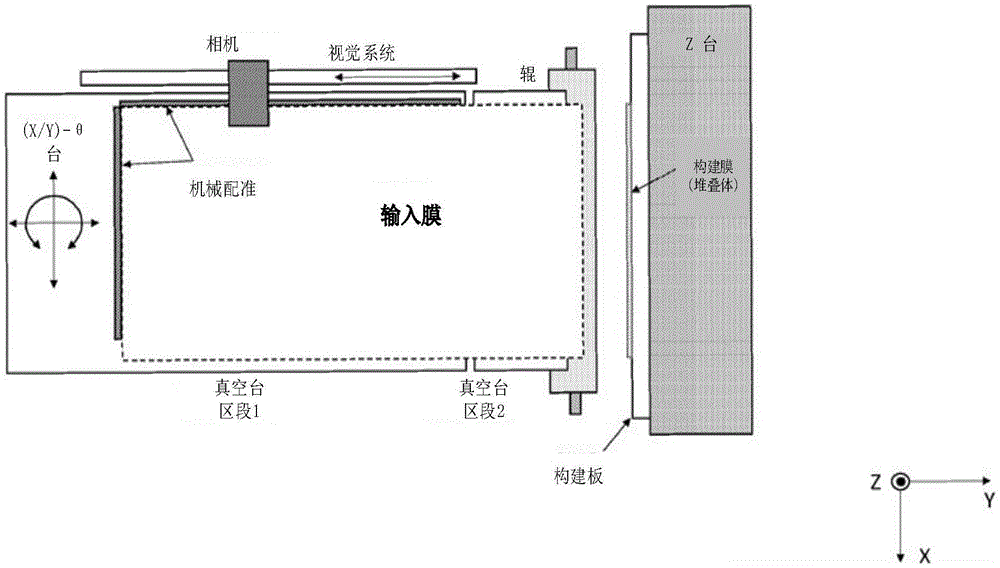
在另一种单辊层压方法中,压合区的形成涉及将如下五个元件联合在一起:(1)层压辊、(2)可变形的支承构件(DSM)、(3)输入膜(包括任何保护衬底)、(4)构建膜(或包括任何下部保护衬底的尚未完成的堆叠体)和(5)构建板。可变形的支承构件的加入是为了在层压期间支承进料膜的整个区域而不引入面内应力。可变形的支承构件可以有效地增加进料膜的厚度并且使其在机械方面更加稳定。这种方法可能的优点是,即使在形成压合区的地方膜也被完全地支承。图10示出了溶剂层压器20,该溶剂层压器包括进料组件22和构建组件(32、34)。进料组件被示出为在膜装载期间基本上水平,并且构建组件被示出为基本上竖直。尽管一个考虑是水平膜装载的便利性,但在角度上也有一些灵活性。第二个考虑是层压应以足够陡的角度进行,使得在没有辊影响的情况下溶剂不会在层压方向上流动。进料组件可以是准密封的盒子,该准密封的盒子包含安装到Z平移平台(例如,气缸或伺服电机)的辊,其中整个组件在Y平移平台(例如,蜗杆驱动件)26上行进。可变形的支承构件28基本上覆盖了盒子的上侧(XY平面)。可变形的支承构件处于张力下,以便它可以在层压之前以平面方式固定进料膜30。可变形的支承构件可以是聚合物(例如,聚酯薄膜),或者可变形的支承构件可以是金属(例如,不锈钢)。合适的材料/厚度允许来自辊的压力均匀地被传递到正被层压的材料。In another single roll lamination method, the formation of the nip zone involves the joining together of five elements as follows: (1) lamination roll, (2) deformable support member (DSM), (3) input film (including any protective substrate), (4) the build membrane (or the unfinished stack including any underlying protective substrate), and (5) the build plate. Deformable support members were added to support the entire area of the feed film during lamination without introducing in-plane stresses. The deformable support member can effectively increase the thickness of the feed film and make it mechanically more stable. A possible advantage of this method is that the membrane is fully supported even where the nip is formed. Figure 10 shows a
在进料膜30(例如,使用限定两个轴线的胶带)被加载和粗略对准之后,可以通过向外壳22施加真空来固定该进料膜,并且然后可以移除保护衬底。可变形的支承构件可以将真空转移到进料膜并且将进料膜牢固地保持就位,从而在整个区域上支承进料膜。必须小心确保这种真空特征不会局部地损害层压。如在前一实施方案中那样,视觉系统可以通过(例如)沿纵向方向扫描来定位膜边缘。用于精确对准膜的平台可以位于进料侧或位于构建侧。在这种情况下,用于精确对准的定位平台34安装在竖直固定板32上。可以使用真空或机械手段将构建板(例如,平坦玻璃板)36刚性地保持到定位平台。构建膜(或堆叠体)38经由胶带、光学接触或低粘性粘合剂附接到构建板。一旦被固定和对准,铰链机构40可以提升进料组件,使得进料组件在与构建组件相同的表面-法线方向上锁定到位。After the
图11展示了使用图10的溶剂层压器的层压过程。图11A示出了处于如图10中的装载位置的层压器。图11B示出了绕X轴线将进料板铰接到竖直位置。在进料板被锁定到位后,在进料膜与构建膜之间形成均匀的间隙。该间隙有利于溶剂的引入,该间隙考虑了堆叠体的最大厚度,并且该间隙还影响层压点处进料膜与构建膜之间的角度。如果间隙小,则两个膜之间的角度同样小,并且毛细作用力可能导致溶剂在层压点之前上升得太多,从而损坏该两个膜。当增加间隙时,辊同样在Y方向上进一步平移以形成压合区,但是两个膜之间的角度增加。如果在边界处刚性固定,可变形的支承构件中的应变随着间隙而增加,并且由辊的气缸或伺服电机施加的压力也可以增加以维持恒定的压合区压力。在形成压合区之后影响两个膜之间角度的其它因素包括在辊伸出之前可变形的支承构件的杨氏模量、厚度和张力。如果所需角度使可变形的支承构件中的大的应变成为必要,则重要的是可变形的支承构件在层压点处不将面内应变转移到输入膜。FIG. 11 illustrates the lamination process using the solvent laminator of FIG. 10 . FIG. 11A shows the laminator in the loading position as in FIG. 10 . Figure 1 IB shows the feed plate being hinged about the X-axis into a vertical position. After the feed plate is locked in place, a uniform gap is created between the feed film and the build film. This gap facilitates the introduction of solvent, takes into account the maximum thickness of the stack, and also affects the angle between the feed film and the build film at the point of lamination. If the gap is small, the angle between the two membranes is equally small, and capillary forces may cause the solvent to rise too much before the point of lamination, damaging both membranes. When the gap is increased, the rollers also translate further in the Y direction to form the nip, but the angle between the two films increases. If rigidly fixed at the boundary, the strain in the deformable support member increases with the gap, and the pressure applied by the roller's cylinders or servo motors can also be increased to maintain a constant nip pressure. Other factors that affect the angle between the two films after the nip is formed include the Young's modulus, thickness and tension of the deformable support member prior to roll extension. If the desired angle necessitates large strains in the deformable support member, it is important that the deformable support member does not transfer in-plane strain to the input membrane at the point of lamination.
用于减轻可变形的支承构件中的应变引起的输入膜上的面内应力的方法是在形成压合区时提供一些滑移。例如,如果膜仅在层压的开始/结束时固定,则真空可以足够弱,以使得膜在最初形成压合区时滑移,从而释放应力。减轻可变形的支承构件中的应变的另一种方法是引入灵活的边界条件。如果应变是在边界附近引入的,而不是在可变形的支承构件的支承膜的部分中引入的,则可能存在施加到输入膜的相对低的应力。图12为图11C的压合区的放大图。图12A示出了间隙的示例,该间隙的宽度W1在两个膜之间形成近似角度θ1。在这种情况下,当辊伸出时,存在处于准均匀应变下的单个可变形的支承构件层。该应变可以部分地传递到输入膜。图12B示出了为了产生更大的角度θ2,将两个膜之间的间隙增大到W2的情况。如果可变形的支承构件具有相同的构造,则将引入更大的应变以形成压合区,并且输入膜可能受到增大的张力。然而,如图12B中所示,可变形的支承构件可以包括支承进料膜的内部部分和基本上释放张力的外部部分。内部部分可以比外部部分具有更高模量的材料,内部部分可以相对于外部部分更厚,或这两者情况皆有。因此,外部部分的目的是产生引起期望的压合区几何形状所需的大部分应变,从而使输入膜被支承但没有面内应力。A method for relieving strain-induced in-plane stress on the input membrane in the deformable support member is to provide some slip when forming the nip. For example, if the film is only set at the beginning/end of lamination, the vacuum can be weak enough to allow the film to slip while initially forming the nip, relieving the stress. Another way to relieve strain in deformable support members is to introduce flexible boundary conditions. If the strain is introduced near the boundary, rather than in the portion of the deformable support member supporting the membrane, there may be relatively low stress applied to the input membrane. FIG. 12 is an enlarged view of the nip area of FIG. 11C . FIG. 12A shows an example of a gap whose width W 1 forms an approximate angle θ 1 between the two films. In this case, there is a single deformable support member layer under quasi-uniform strain when the roller is extended. This strain can be partially transferred to the input membrane. Figure 12B shows the case where the gap between the two films is increased to W2 in order to create a larger angle Θ2 . If the deformable support members had the same configuration, more strain would be introduced to form the nip, and the input membrane could be subject to increased tension. However, as shown in Figure 12B, the deformable support member may include an inner portion that supports the feed film and an outer portion that substantially relieves tension. The inner portion may be of a higher modulus material than the outer portion, the inner portion may be thicker than the outer portion, or both. Therefore, the purpose of the outer portion is to generate most of the strain needed to induce the desired nip geometry so that the input membrane is supported but free of in-plane stresses.
图11C示出了辊(在Y方向上)的伸出,从而形成压合区。低廓形分配头可以在提升进料台之前就位,或者低廓形分配头可以在提升进料台之后被插置。在形成压合区之后,注射针可以在其缩回时分配一次或多次喷射,从而产生溶剂储存器。溶剂分配压力可以被最小化,以避免飞溅和相关联的膜损坏。图11D示出了辊在Z方向上的平移,从而将两个膜粘接在一起。在行程结束时,辊缩回并且返回到开始位置,并且进料台返回到装载位置。Figure 11C shows the extension of the rollers (in the Y direction), forming the nip. The low profile dispense head can be in place prior to raising the feed table, or the low profile dispense head can be inserted after the feed table is raised. After the nip is formed, the injection needle can dispense one or more shots as it retracts, creating a solvent reservoir. Solvent dispensing pressure can be minimized to avoid splashing and associated membrane damage. Figure 1 ID shows the translation of the roller in the Z direction to bond the two films together. At the end of the stroke, the rollers retract and return to the starting position, and the feed table returns to the loading position.
在这种构造中可能存在关于可变形的支承构件对层压质量的影响的担忧。如果可变形的支承构件(例如,通过孔)提供真空以固定进料膜,则可能存在形成粘接所需的压力不足的区域。在这种情况下,膜可能过度暴露于溶剂,并且在没有足够压力的情况下,可能不会发生可靠的粘接。在一构造中,真空孔可以仅存在于母片材的牺牲部分上。例如,真空孔可以仅沿着横向方向存在于层压件的顶部和底部处。这可以提供对膜的充分支承,而不显著影响良率。In such configurations there may be concerns regarding the effect of deformable support members on the lamination quality. If the deformable support member provides vacuum (eg, through holes) to secure the feed film, there may be areas where insufficient pressure is required to form a bond. In this case, the membrane may be over-exposed to the solvent, and without sufficient pressure, reliable bonding may not occur. In one configuration, the vacuum holes may only exist on the sacrificial portion of the mother sheet. For example, vacuum holes may only exist at the top and bottom of the laminate along the transverse direction. This can provide sufficient support for the film without significantly impacting yield.
因为可变形的支承构件是层压的密切部分,所以可变形的支承构件应该具有优异的厚度均匀性和表面质量。否则,可能存在导致通读纹理和局部面内应力的压力不均匀性。为了确保压合区中的压力均匀性,还需要在纵向方向上提供与在横向方向上不同的张力。优选的是,在层压期间可变形的支承构件与辊基本上共形,并且在辊的端部处在可变形的支承构件中存在的张力可能是破坏性的。这可以通过将辊/可变形的支承构件的长度充分延伸超过膜的宽度、或者通过释放一些横向方向上的应力来克服。后者可以通过使可变形的支承构件的位于压合区之外的区域更具有柔性来实现,通过使可变形的支承构件的位于压合区之外的区域变薄或使用不同材料以使得该区域更具有柔性。这类似于上述的用于在辊接合时使可变形的支承构件中的纵向方向应变最小化的方法。Since the deformable support member is an intimate part of the lamination, the deformable support member should have excellent thickness uniformity and surface quality. Otherwise, there may be pressure inhomogeneities that cause read-through textures and local in-plane stresses. In order to ensure uniformity of pressure in the nip zone, it is also necessary to provide a different tension in the longitudinal direction than in the transverse direction. It is preferred that the deformable support member substantially conforms to the roll during lamination and that tension existing in the deformable support member at the ends of the roll may be destructive. This can be overcome by extending the length of the roller/deformable support member well beyond the width of the membrane, or by relieving some of the stress in the transverse direction. The latter can be achieved by making the area of the deformable support member outside of the nip more flexible, by thinning the area of the deformable support member outside of the nip or using a different material such that the Regions are more flexible. This is similar to the method described above for minimizing longitudinal strain in the deformable support member upon roller engagement.
通常,与压合区密切接触的元件的材料和公差必须仔细地选择。光学质量标准通常是优选的,以便避免在层压件中的可能由压力的局部不均匀性和溶剂暴露导致的透印纹理或通读纹理。这些不均匀性可能是由于对片材的面内和法向的影响而产生的。必须仔细检查辊密度、厚度和表面不均匀性,包括材料均匀性、辊铸造/机加工过程和相关联的缺陷(例如,铸造辊材料中的气泡或夹杂物)。辊轴线必须与构建板精确地对准,以避免横向方向压力斜变。必须仔细检查保护衬底厚度的均匀性以及保护衬底层压的清洁度。必须仔细检查构建板的厚度均匀性和表面质量。示例性的构建板材料包括抛光玻璃、抛光金属和可能的(例如,单元浇铸的)聚合物。后者可以有助于单次使用的构建板,或者在大面积层压件中减少构建板的重量。必须仔细检查构建平台的平坦度。如果使用真空将构建板保持到构建平台,则真空特征不能透印到层压件。这可以通过使真空特征位于层压区域之外、使这些真空特征足够小、或者使用具有足够刚度的构建板来实现,使得这些真空特征不影响层压质量。当然,构成压合区的所有元件必须没有碎屑。在层压中捕获的颗粒影响外观良率,其中溶剂影响的面积通常远大于物理颗粒。层压件外部的颗粒可能会影响堆叠体成品的局部平坦度/透射波前质量。后者在堆叠体成品的一个表面随后被结合到另一个光学表面时可能表现为凹痕或凹坑,这些凹痕或凹坑特别成问题。Often, the materials and tolerances of the components that come into close contact with the nip must be carefully selected. Optical quality criteria are generally preferred in order to avoid print-through or read-through textures in the laminate that may be caused by local non-uniformities in pressure and solvent exposure. These inhomogeneities may be due to in-plane and normal effects on the sheet. Roll density, thickness, and surface non-uniformity must be carefully inspected, including material uniformity, roll casting/machining process, and associated defects (eg, air bubbles or inclusions in cast roll material). The roller axis must be precisely aligned with the build plate to avoid pressure ramps in the transverse direction. The uniformity of the protective substrate thickness and the cleanliness of the protective substrate lamination must be carefully checked. Build plates must be carefully checked for thickness uniformity and surface quality. Exemplary build plate materials include polished glass, polished metal, and possibly (eg, unit cast) polymers. The latter can facilitate single-use build plates, or reduce build plate weight in large-area laminates. The flatness of the build platform must be carefully checked. If a vacuum is used to hold the build plate to the build platform, the vacuum features cannot show through to the laminate. This can be accomplished by locating the vacuum features outside the lamination area, making them small enough, or using a build plate that is stiff enough that they do not affect lamination quality. Of course, all elements making up the nip must be free of debris. Particles trapped in lamination affect cosmetic yield, where the area affected by the solvent is usually much larger than the physical particles. Particles on the outside of the laminate may affect the local flatness/transmitted wavefront quality of the finished stack. The latter may appear as indentations or pits, which are particularly problematic when one surface of the finished stack is subsequently bonded to another optical surface.
必须仔细检查用于将第一延迟膜层片附接(即,临时固定)到构建板的方法。该过程优选地使用层压器(例如,在粘接溶剂分配被关闭的情况下)完成,以使得机器视觉系统以相同的精度、相同的便利性和最少的处理来放置所有膜。附接方法可以是施加到母片材的牺牲区域或构建板的粘合剂(例如,在层压开始/结束时沿着横向方向的双面胶带),或者附接方法可以是全面结合。粘合剂可以优选地是可转移的,而不需要将载体基板转移到构建板(如用粘合胶带)。粘合剂的功能性目的是以与粘接过程相同的一些要求固定第一层片(即,以最小的面内应力维持取向精度)。如果在顶部/底部处进行离散附接,则在后续的层压步骤期间,膜不能在面内显著地移动。如果在随后的溶剂粘接中在层压结束时将过量的溶剂推出,则过量的溶剂不能在堆叠体下进行芯吸而损坏堆叠体。离散附接方法可以在允许膜在层压区域中机械地“浮动”方面具有一些益处,这可以有助于降低面内应力。The method used to attach (ie, temporarily fix) the first retardation film ply to the build plate must be carefully examined. This process is preferably done using the laminator (eg, with the adhesive solvent dispense turned off) so that the machine vision system places all the films with equal precision, equal ease, and minimal handling. The attachment method can be an adhesive applied to a sacrificial area of the master sheet or the build plate (eg double sided tape in the transverse direction at the start/end of lamination) or it can be full bonding. The adhesive may preferably be transferable without the need to transfer the carrier substrate to the build plate (eg with adhesive tape). The functional purpose of the adhesive is to secure the first ply with some of the same requirements as the bonding process (ie, maintain orientation accuracy with minimal in-plane stress). If discrete attachments are made at the top/bottom, the film cannot move significantly in-plane during subsequent lamination steps. If the excess solvent is pushed out at the end of lamination during subsequent solvent bonding, the excess solvent cannot wick under the stack and damage the stack. The discrete attachment method may have some benefit in allowing the film to mechanically "float" in the lamination area, which may help reduce in-plane stress.
如果保护衬底位于延迟膜的下侧上,则保护衬底优选地具有低表面能。保护衬底(或未受保护的延迟器)可以具有高表面能,因此当与构建板接触时产生随机的光学接触,从而引起面内应力。此外,在第一层片的附接期间在这些表面之间的界面处截留的任何空气可以在堆叠体成品中产生局部压力不均匀性和纹理。如在所有先前关于粘接的分析中,当将第一层片粘接到第二层片时,在附接第一层片时的任何面内应力可以被带入。If the protective substrate is located on the lower side of the retardation film, the protective substrate preferably has a low surface energy. The protective substrate (or unprotected retarder) can have a high surface energy and thus create random optical contacts when in contact with the build plate, causing in-plane stresses. Furthermore, any air trapped at the interface between these surfaces during attachment of the first ply can create localized pressure non-uniformities and textures in the finished stack. As in all previous analyzes on bonding, when bonding a first ply to a second ply, any in-plane stresses while attaching the first ply can be brought into play.
为了更完全的支承,可以使用先前施加到第一层片保护衬底或构建板的粘合剂来完成第一层片到构建板的全面结合。这可以通过浸渍或喷涂构建板的层压侧,然后附接释放保护衬底来完成,当构建板安装在层压器中时,可以移除该释放保护衬底。如果必须清洁和再次使用构建板,则粘合剂优选地具有使其易于用水或非腐蚀性溶剂(例如,异丙醇)去除的化学性质。粘合剂理想地以精确的厚度施加,并且/或者具有最小的厚度(<1微米),使得粘合剂厚度的任何不均匀性都不会影响层压件的平坦度。后者的极端示例是水溶性的自组装单层(self-assembling-monolayer,SAM),其中头部/尾部基团(head/tail groups)提供了构建板材料与保护衬底的充分附接。粘性可能优选地足以在层压期间可靠地固定堆叠体,但是该粘性低于保护衬底对构建板的粘性。后者允许容易地从构建板移除堆叠体成品(在两侧上具有保护衬底)。如果粘合剂层是极薄(例如,SAM)的,则当第一层片被层压时,粘合剂层可能不提供顺应性。这种情况与溶剂粘接的不同之处可以在于,在附接期间在压合区中可能没有液体。理想地,层压过程不依赖于构建板处的顺应性来最小化面内应力。然而,第一层片与构建板之间的一些机械隔离可以经由保护衬底的机械特性(厚度/模量/表面能)来实现。在一些情况下,粘合剂在附接第一层片时可以呈液体形式,因此粘合剂可以提供一些润滑,从而使面内应力最小化。例如,具有低粘度的氰基丙烯酸酯粘合剂可以被分配在压合区中,并且滚动该粘合剂以附接第一层片。For more complete support, the full bond of the first ply to the build plate can be accomplished using the adhesive previously applied to the first ply protective substrate or build plate. This can be done by dipping or spraying the lamination side of the build plate and then attaching a protective release liner which can be removed when the build plate is installed in the laminator. If the build plate must be cleaned and reused, the adhesive preferably has a chemistry that makes it easy to remove with water or a non-aggressive solvent (eg, isopropanol). The adhesive is ideally applied at a precise thickness and/or with a minimum thickness (<1 micron) so that any non-uniformity in adhesive thickness does not affect the flatness of the laminate. An extreme example of the latter is a water-soluble self-assembling-monolayer (SAM), where head/tail groups provide sufficient attachment of the build plate material to the protective substrate. The tack may preferably be sufficient to securely hold the stack during lamination, but lower than the tack of the protective substrate to the build plate. The latter allows easy removal of the finished stack (with protective substrates on both sides) from the build plate. If the adhesive layer is extremely thin (eg, SAM), the adhesive layer may not provide compliance when the first ply is laminated. This situation may differ from solvent bonding in that there may be no liquid in the nip during attachment. Ideally, the lamination process does not rely on compliance at the build plate to minimize in-plane stress. However, some mechanical isolation between the first ply and the build plate can be achieved via the mechanical properties (thickness/modulus/surface energy) of the protective substrate. In some cases, the adhesive may be in liquid form when the first ply is attached, so the adhesive may provide some lubrication, thereby minimizing in-plane stress. For example, a cyanoacrylate adhesive having a low viscosity may be dispensed in the nip zone and the adhesive rolled to attach the first ply.
存在用于将第一层片附接到构建板的其它可能方法。这可以使用从构建平台通过构建板传递的真空来完成。这些真空特征可以仅位于母片材的牺牲部分上。如参照真空辊所讨论的,能够实现真空压紧的非常小的特征可能会破坏延迟器堆叠体的光学特性。还可以使用第一层片到构建板的静电吸引来实现全面附接。附接也可以经由保护衬底(或裸延迟器)与构建板化学物质之间的范德华吸引力(Van der Waals attraction force)来实现。可以在压合区中分配合适的液体以促进化学键合,该化学键合对于固定来说足够强,但是当剥离完成的堆叠体时容易破坏该化学键合。There are other possible methods for attaching the first ply to the build plate. This can be done using vacuum delivered from the build platform through the build plate. These vacuum features may be located only on sacrificial portions of the parent sheet. As discussed with reference to vacuum rolls, very small features that enable vacuum compaction can destroy the optical properties of the retarder stack. Full attachment can also be achieved using electrostatic attraction of the first ply to the build plate. Attachment can also be achieved via the Van der Waals attraction force between the protective substrate (or bare retarder) and the build plate chemistry. A suitable liquid can be dispensed in the nip zone to promote a chemical bond that is strong enough for fixation but is easily broken when the completed stack is peeled off.
Claims (11)
Applications Claiming Priority (3)
| Application Number | Priority Date | Filing Date | Title |
|---|---|---|---|
| US202063041978P | 2020-06-21 | 2020-06-21 | |
| US63/041,978 | 2020-06-21 | ||
| PCT/US2021/038183 WO2021262569A1 (en) | 2020-06-21 | 2021-06-21 | Equipment and processes for precision fabrication of solvent-laminated retarder-stacks |
Publications (2)
| Publication Number | Publication Date |
|---|---|
| CN116348300A true CN116348300A (en) | 2023-06-27 |
| CN116348300B CN116348300B (en) | 2025-11-18 |
Family
ID=79022956
Family Applications (1)
| Application Number | Title | Priority Date | Filing Date |
|---|---|---|---|
| CN202180059503.4A Active CN116348300B (en) | 2020-06-21 | 2021-06-21 | Equipment and methods for precision manufacturing of solvent-laminated delayer stacks |
Country Status (6)
| Country | Link |
|---|---|
| US (1) | US11628655B2 (en) |
| EP (1) | EP4168248A4 (en) |
| JP (1) | JP2023552257A (en) |
| KR (1) | KR20230029821A (en) |
| CN (1) | CN116348300B (en) |
| WO (1) | WO2021262569A1 (en) |
Families Citing this family (1)
| Publication number | Priority date | Publication date | Assignee | Title |
|---|---|---|---|---|
| KR102748338B1 (en) * | 2020-03-27 | 2025-01-02 | 삼성디스플레이 주식회사 | Bonding apparatus and manufacturing method of display device using the same |
Citations (7)
| Publication number | Priority date | Publication date | Assignee | Title |
|---|---|---|---|---|
| US6367532B1 (en) * | 1999-02-18 | 2002-04-09 | Sanei Giken Co., Ltd. | Laminator |
| US6638583B1 (en) * | 2000-03-16 | 2003-10-28 | Colorlink, Inc. | Method and apparatus for laminating stacks of polycarbonate films |
| CN1489520A (en) * | 2001-02-16 | 2004-04-14 | ͨ�õ�����˾ | Apparatus for making low birefringence plastic films and sheets |
| US20090279030A1 (en) * | 2005-10-20 | 2009-11-12 | Nitto Denko Corporation | Laminated film |
| CN104066567A (en) * | 2012-01-23 | 2014-09-24 | 麦克德米德印刷方案股份有限公司 | Improved laminating apparatus and method of using the same |
| CN104898310A (en) * | 2014-03-06 | 2015-09-09 | Nlt科技股份有限公司 | Substrate lamination device, substrate lamination method, and stereoscopic display device |
| CN108570290A (en) * | 2017-03-07 | 2018-09-25 | 伦姆胶带有限公司 | Method and apparatus for adhesive activation |
Family Cites Families (9)
| Publication number | Priority date | Publication date | Assignee | Title |
|---|---|---|---|---|
| JP2001287271A (en) * | 2000-04-10 | 2001-10-16 | Sanee Giken Kk | Method and laminator for laminating film to substrate |
| JP2003025448A (en) * | 2001-07-16 | 2003-01-29 | Mitsui Chemicals Inc | Device for temporarily laminating film for laminator |
| JP4241203B2 (en) * | 2002-06-13 | 2009-03-18 | 東レ株式会社 | Flexible film laminating method, laminating apparatus, and circuit board manufacturing method |
| JPWO2006103715A1 (en) * | 2005-03-25 | 2008-09-04 | Jsr株式会社 | Polarizing plate manufacturing method and polarizing plate manufacturing apparatus |
| JP2010085980A (en) * | 2008-09-03 | 2010-04-15 | Jsr Corp | Wavelength plate and its manufacturing method |
| JP2010155358A (en) * | 2008-12-26 | 2010-07-15 | Fuji Xerox Co Ltd | Laminating device and lamination method |
| KR101254749B1 (en) * | 2010-10-12 | 2013-04-15 | (주)와이티에스 | Apparatus for Manufacturing Stereoscopic Image Display Device |
| JP2013174799A (en) * | 2012-02-27 | 2013-09-05 | Kyocera Corp | Polarizer sticking device and sticking method of polarizer using the same |
| JP5943354B2 (en) * | 2013-07-23 | 2016-07-05 | 住友化学株式会社 | Optical display device production system |
-
2021
- 2021-06-21 KR KR1020237002155A patent/KR20230029821A/en active Pending
- 2021-06-21 JP JP2022579072A patent/JP2023552257A/en active Pending
- 2021-06-21 WO PCT/US2021/038183 patent/WO2021262569A1/en not_active Ceased
- 2021-06-21 CN CN202180059503.4A patent/CN116348300B/en active Active
- 2021-06-21 US US17/352,586 patent/US11628655B2/en active Active
- 2021-06-21 EP EP21828276.2A patent/EP4168248A4/en not_active Withdrawn
Patent Citations (7)
| Publication number | Priority date | Publication date | Assignee | Title |
|---|---|---|---|---|
| US6367532B1 (en) * | 1999-02-18 | 2002-04-09 | Sanei Giken Co., Ltd. | Laminator |
| US6638583B1 (en) * | 2000-03-16 | 2003-10-28 | Colorlink, Inc. | Method and apparatus for laminating stacks of polycarbonate films |
| CN1489520A (en) * | 2001-02-16 | 2004-04-14 | ͨ�õ�����˾ | Apparatus for making low birefringence plastic films and sheets |
| US20090279030A1 (en) * | 2005-10-20 | 2009-11-12 | Nitto Denko Corporation | Laminated film |
| CN104066567A (en) * | 2012-01-23 | 2014-09-24 | 麦克德米德印刷方案股份有限公司 | Improved laminating apparatus and method of using the same |
| CN104898310A (en) * | 2014-03-06 | 2015-09-09 | Nlt科技股份有限公司 | Substrate lamination device, substrate lamination method, and stereoscopic display device |
| CN108570290A (en) * | 2017-03-07 | 2018-09-25 | 伦姆胶带有限公司 | Method and apparatus for adhesive activation |
Also Published As
| Publication number | Publication date |
|---|---|
| JP2023552257A (en) | 2023-12-15 |
| US11628655B2 (en) | 2023-04-18 |
| KR20230029821A (en) | 2023-03-03 |
| CN116348300B (en) | 2025-11-18 |
| EP4168248A4 (en) | 2024-07-24 |
| WO2021262569A1 (en) | 2021-12-30 |
| EP4168248A1 (en) | 2023-04-26 |
| US20210394498A1 (en) | 2021-12-23 |
Similar Documents
| Publication | Publication Date | Title |
|---|---|---|
| CN103085438B (en) | Optical sheet applying method, device and the adhesive sheet used thereof | |
| JP5070209B2 (en) | High-yield bonding process for producing polycarbonate polarizing lenses | |
| CN101910925B (en) | Method and apparatus for continuous manufacturing of liquid crystal display elements | |
| KR102209634B1 (en) | Cementing device, cementing method, system for producing optical display device, and method for producing optical display device | |
| KR102172312B1 (en) | Bonding apparatus, bonding method, system for manufacturing optical display devices, and method for manufacturing optical display device | |
| TW201113136A (en) | Roll of continuous web of optical film laminate with predefined slit lines, and method and system for manufacturing the same | |
| CN102043278A (en) | Method and system for continuously manufacturing liquid-crystal display element | |
| TW200304573A (en) | Apparatus and method for fabricating bonded substrate | |
| CN101551485A (en) | Polarizing disc and manufacturing installation and manufacturing method thereof, and optical laminating body | |
| CN101639619A (en) | Stereoscopic image display device and method of manufacturing the same | |
| TW200848346A (en) | Apparatus for cutting an adhesive film, equipment for sticking an adhesive film having the same, method for cutting an adhesive film using the same, and method for sticking an adhesive film using the same | |
| TW201211621A (en) | Method and system for producing liquid crystal panel | |
| CN116348300B (en) | Equipment and methods for precision manufacturing of solvent-laminated delayer stacks | |
| KR20190078799A (en) | Protective film peeling device and system for attaching film to panel having the same | |
| WO2015029998A1 (en) | Film bonding device, optical-display-device production system, and optical-display-device production method | |
| KR102325151B1 (en) | Bonding device, system for producing optical display device, bonding method, and method for producing optical display device | |
| JP3444536B2 (en) | Semiconductor laser device manufacturing method and cleavage device | |
| JP3431951B2 (en) | Semiconductor substrate bonding equipment | |
| KR102209637B1 (en) | Bonding device, bonding method, production system for optical display device, and production method for optical display device | |
| CN113031320B (en) | Method for producing laminated body | |
| JPH09316399A (en) | Substrate laminating apparatus and substrate laminating method | |
| JP5843130B2 (en) | Optical film sticking device to substrate | |
| TWI872163B (en) | Method for producing laminate and laminating apparatus | |
| JP2007210265A (en) | Optical film pasting apparatus, optical film pasting method, and display panel manufacturing method | |
| KR101504222B1 (en) | sheet laminator |
Legal Events
| Date | Code | Title | Description |
|---|---|---|---|
| PB01 | Publication | ||
| PB01 | Publication | ||
| SE01 | Entry into force of request for substantive examination | ||
| SE01 | Entry into force of request for substantive examination | ||
| GR01 | Patent grant | ||
| GR01 | Patent grant |