CN116348170A - Nebulizer device optimization and its use for improving aerosol parameter AMARKND - Google Patents
Nebulizer device optimization and its use for improving aerosol parameter AMARKND Download PDFInfo
- Publication number
- CN116348170A CN116348170A CN202180072082.9A CN202180072082A CN116348170A CN 116348170 A CN116348170 A CN 116348170A CN 202180072082 A CN202180072082 A CN 202180072082A CN 116348170 A CN116348170 A CN 116348170A
- Authority
- CN
- China
- Prior art keywords
- aerosol
- pirfenidone
- mixing chamber
- aqueous solution
- reservoir
- Prior art date
- Legal status (The legal status is an assumption and is not a legal conclusion. Google has not performed a legal analysis and makes no representation as to the accuracy of the status listed.)
- Pending
Links
Images


Classifications
-
- A—HUMAN NECESSITIES
- A61—MEDICAL OR VETERINARY SCIENCE; HYGIENE
- A61M—DEVICES FOR INTRODUCING MEDIA INTO, OR ONTO, THE BODY; DEVICES FOR TRANSDUCING BODY MEDIA OR FOR TAKING MEDIA FROM THE BODY; DEVICES FOR PRODUCING OR ENDING SLEEP OR STUPOR
- A61M11/00—Sprayers or atomisers specially adapted for therapeutic purposes
- A61M11/005—Sprayers or atomisers specially adapted for therapeutic purposes using ultrasonics
-
- A—HUMAN NECESSITIES
- A61—MEDICAL OR VETERINARY SCIENCE; HYGIENE
- A61K—PREPARATIONS FOR MEDICAL, DENTAL OR TOILETRY PURPOSES
- A61K31/00—Medicinal preparations containing organic active ingredients
- A61K31/33—Heterocyclic compounds
- A61K31/395—Heterocyclic compounds having nitrogen as a ring hetero atom, e.g. guanethidine or rifamycins
- A61K31/435—Heterocyclic compounds having nitrogen as a ring hetero atom, e.g. guanethidine or rifamycins having six-membered rings with one nitrogen as the only ring hetero atom
- A61K31/44—Non condensed pyridines; Hydrogenated derivatives thereof
- A61K31/4418—Non condensed pyridines; Hydrogenated derivatives thereof having a carbocyclic group directly attached to the heterocyclic ring, e.g. cyproheptadine
-
- A—HUMAN NECESSITIES
- A61—MEDICAL OR VETERINARY SCIENCE; HYGIENE
- A61K—PREPARATIONS FOR MEDICAL, DENTAL OR TOILETRY PURPOSES
- A61K9/00—Medicinal preparations characterised by special physical form
-
- A—HUMAN NECESSITIES
- A61—MEDICAL OR VETERINARY SCIENCE; HYGIENE
- A61K—PREPARATIONS FOR MEDICAL, DENTAL OR TOILETRY PURPOSES
- A61K9/00—Medicinal preparations characterised by special physical form
- A61K9/0012—Galenical forms characterised by the site of application
- A61K9/007—Pulmonary tract; Aromatherapy
- A61K9/0073—Sprays or powders for inhalation; Aerolised or nebulised preparations generated by other means than thermal energy
- A61K9/0078—Sprays or powders for inhalation; Aerolised or nebulised preparations generated by other means than thermal energy for inhalation via a nebulizer such as a jet nebulizer, ultrasonic nebulizer, e.g. in the form of aqueous drug solutions or dispersions
-
- A—HUMAN NECESSITIES
- A61—MEDICAL OR VETERINARY SCIENCE; HYGIENE
- A61K—PREPARATIONS FOR MEDICAL, DENTAL OR TOILETRY PURPOSES
- A61K9/00—Medicinal preparations characterised by special physical form
- A61K9/08—Solutions
-
- A—HUMAN NECESSITIES
- A61—MEDICAL OR VETERINARY SCIENCE; HYGIENE
- A61M—DEVICES FOR INTRODUCING MEDIA INTO, OR ONTO, THE BODY; DEVICES FOR TRANSDUCING BODY MEDIA OR FOR TAKING MEDIA FROM THE BODY; DEVICES FOR PRODUCING OR ENDING SLEEP OR STUPOR
- A61M11/00—Sprayers or atomisers specially adapted for therapeutic purposes
- A61M11/001—Particle size control
- A61M11/003—Particle size control by passing the aerosol trough sieves or filters
-
- A—HUMAN NECESSITIES
- A61—MEDICAL OR VETERINARY SCIENCE; HYGIENE
- A61M—DEVICES FOR INTRODUCING MEDIA INTO, OR ONTO, THE BODY; DEVICES FOR TRANSDUCING BODY MEDIA OR FOR TAKING MEDIA FROM THE BODY; DEVICES FOR PRODUCING OR ENDING SLEEP OR STUPOR
- A61M15/00—Inhalators
- A61M15/0001—Details of inhalators; Constructional features thereof
- A61M15/0013—Details of inhalators; Constructional features thereof with inhalation check valves
-
- A—HUMAN NECESSITIES
- A61—MEDICAL OR VETERINARY SCIENCE; HYGIENE
- A61M—DEVICES FOR INTRODUCING MEDIA INTO, OR ONTO, THE BODY; DEVICES FOR TRANSDUCING BODY MEDIA OR FOR TAKING MEDIA FROM THE BODY; DEVICES FOR PRODUCING OR ENDING SLEEP OR STUPOR
- A61M15/00—Inhalators
- A61M15/0001—Details of inhalators; Constructional features thereof
- A61M15/0021—Mouthpieces therefor
-
- A—HUMAN NECESSITIES
- A61—MEDICAL OR VETERINARY SCIENCE; HYGIENE
- A61M—DEVICES FOR INTRODUCING MEDIA INTO, OR ONTO, THE BODY; DEVICES FOR TRANSDUCING BODY MEDIA OR FOR TAKING MEDIA FROM THE BODY; DEVICES FOR PRODUCING OR ENDING SLEEP OR STUPOR
- A61M15/00—Inhalators
- A61M15/0085—Inhalators using ultrasonics
-
- A—HUMAN NECESSITIES
- A61—MEDICAL OR VETERINARY SCIENCE; HYGIENE
- A61M—DEVICES FOR INTRODUCING MEDIA INTO, OR ONTO, THE BODY; DEVICES FOR TRANSDUCING BODY MEDIA OR FOR TAKING MEDIA FROM THE BODY; DEVICES FOR PRODUCING OR ENDING SLEEP OR STUPOR
- A61M15/00—Inhalators
- A61M15/0086—Inhalation chambers
-
- A—HUMAN NECESSITIES
- A61—MEDICAL OR VETERINARY SCIENCE; HYGIENE
- A61M—DEVICES FOR INTRODUCING MEDIA INTO, OR ONTO, THE BODY; DEVICES FOR TRANSDUCING BODY MEDIA OR FOR TAKING MEDIA FROM THE BODY; DEVICES FOR PRODUCING OR ENDING SLEEP OR STUPOR
- A61M11/00—Sprayers or atomisers specially adapted for therapeutic purposes
- A61M11/001—Particle size control
-
- A—HUMAN NECESSITIES
- A61—MEDICAL OR VETERINARY SCIENCE; HYGIENE
- A61M—DEVICES FOR INTRODUCING MEDIA INTO, OR ONTO, THE BODY; DEVICES FOR TRANSDUCING BODY MEDIA OR FOR TAKING MEDIA FROM THE BODY; DEVICES FOR PRODUCING OR ENDING SLEEP OR STUPOR
- A61M15/00—Inhalators
- A61M15/0001—Details of inhalators; Constructional features thereof
- A61M15/0013—Details of inhalators; Constructional features thereof with inhalation check valves
- A61M15/0015—Details of inhalators; Constructional features thereof with inhalation check valves located upstream of the dispenser, i.e. not traversed by the product
-
- A—HUMAN NECESSITIES
- A61—MEDICAL OR VETERINARY SCIENCE; HYGIENE
- A61M—DEVICES FOR INTRODUCING MEDIA INTO, OR ONTO, THE BODY; DEVICES FOR TRANSDUCING BODY MEDIA OR FOR TAKING MEDIA FROM THE BODY; DEVICES FOR PRODUCING OR ENDING SLEEP OR STUPOR
- A61M15/00—Inhalators
- A61M15/0001—Details of inhalators; Constructional features thereof
- A61M15/0018—Details of inhalators; Constructional features thereof with exhalation check valves
-
- A—HUMAN NECESSITIES
- A61—MEDICAL OR VETERINARY SCIENCE; HYGIENE
- A61M—DEVICES FOR INTRODUCING MEDIA INTO, OR ONTO, THE BODY; DEVICES FOR TRANSDUCING BODY MEDIA OR FOR TAKING MEDIA FROM THE BODY; DEVICES FOR PRODUCING OR ENDING SLEEP OR STUPOR
- A61M16/00—Devices for influencing the respiratory system of patients by gas treatment, e.g. ventilators; Tracheal tubes
- A61M16/0003—Accessories therefor, e.g. sensors, vibrators, negative pressure
- A61M2016/0015—Accessories therefor, e.g. sensors, vibrators, negative pressure inhalation detectors
- A61M2016/0018—Accessories therefor, e.g. sensors, vibrators, negative pressure inhalation detectors electrical
- A61M2016/0024—Accessories therefor, e.g. sensors, vibrators, negative pressure inhalation detectors electrical with an on-off output signal, e.g. from a switch
-
- A—HUMAN NECESSITIES
- A61—MEDICAL OR VETERINARY SCIENCE; HYGIENE
- A61M—DEVICES FOR INTRODUCING MEDIA INTO, OR ONTO, THE BODY; DEVICES FOR TRANSDUCING BODY MEDIA OR FOR TAKING MEDIA FROM THE BODY; DEVICES FOR PRODUCING OR ENDING SLEEP OR STUPOR
- A61M2209/00—Ancillary equipment
- A61M2209/06—Packaging for specific medical equipment
Landscapes
- Health & Medical Sciences (AREA)
- Engineering & Computer Science (AREA)
- Life Sciences & Earth Sciences (AREA)
- Veterinary Medicine (AREA)
- Public Health (AREA)
- General Health & Medical Sciences (AREA)
- Animal Behavior & Ethology (AREA)
- Biomedical Technology (AREA)
- Hematology (AREA)
- Heart & Thoracic Surgery (AREA)
- Anesthesiology (AREA)
- Bioinformatics & Cheminformatics (AREA)
- Pulmonology (AREA)
- Chemical & Material Sciences (AREA)
- Medicinal Chemistry (AREA)
- Pharmacology & Pharmacy (AREA)
- Epidemiology (AREA)
- Dispersion Chemistry (AREA)
- Otolaryngology (AREA)
- Pharmaceuticals Containing Other Organic And Inorganic Compounds (AREA)
- Medicinal Preparation (AREA)
- Investigating Or Analysing Materials By Optical Means (AREA)
- Investigating, Analyzing Materials By Fluorescence Or Luminescence (AREA)
Abstract
Disclosed herein is a nebulizer comprising a cup reservoir containing an aqueous solution of pirfenidone, a cup reservoir cap, an aerosol generator, an aerosol mixing chamber in which freshly generated aerosol resides until inhaled, a one-way inhalation valve, a mouthpiece and a one-way exhalation valve. The present invention allows for the maintenance of atmospheric pressure within the drug cup reservoir during aerosolization and optimizes the volume of the aerosol mixing chamber to minimize droplet growth and/or condensation between freshly generated aerosol droplets, impingement of aerosol on the aerosol mixing chamber walls, during exhalation, prior to inhalation, or during inhalation. The larger aerosol mixing chamber volume also allows aerosol to accumulate during the exhalation phase. Although ventilation produces a greater average population of aerosol-producing droplets than a non-ventilated aerosol generator, the combined effects of the present invention increase the device output rate of respirable aerosol droplets, increasing the Cmax and AUC of pirfenidone, thereby improving the treatment or prevention of various diseases, including diseases associated with the lungs, heart and kidneys, including fibrosis, inflammatory conditions and transplant rejection.
Description
This application claims priority from U.S. provisional application SN 63/081,735, which is incorporated herein by reference.
Background
Liquid nebulization of solutions containing active pharmaceutical ingredients has many advantages for delivering drugs to the lungs, such as large dose volumes, large respirable doses, and immediate bioavailable delivery doses. However, performance standards vary widely across several tens of atomizer device mechanisms and structures. Furthermore, the properties of any particular Active Pharmaceutical Ingredient (API) and formulation may vary depending on the design and performance criteria of the nebulizer.
Furthermore, when an aqueous solution containing an API is converted to an aerosol by a nebulizer, each Active Pharmaceutical Ingredient (API) behaves differently. The inherently different and unpredictable physicochemical properties of the API and formulation determine the device and delivery parameters that are capable of delivering a therapeutically effective dose of the API in aerosol form. For this reason, every new attempt to deliver APIs into aerosols by nebulization needs to overcome the unpredictable challenges encountered during drug and device development. This means that nebulizer devices selected for one drug may not be suitable for a different drug based on unpredictable nebulizer design and performance differences, and if an incorrect nebulizer is used, the design of the device may not be sufficient to deliver a therapeutically effective dose.
In the absence of a therapeutically effective dose of aerosol to produce a particular API, the pharmacodynamic profile of the API may render the API unusable as an aerosol, and this challenge requires the development of specific conditions and characteristics of all aqueous solutions placed in the nebulizer, the operation of the nebulizer device to produce a therapeutically effective aerosol, and the construction of the device that can be determined by the unique characteristics of the API molecules dissolved in the solution as they are converted into an aerosol.
Disclosure of Invention
Described herein are nebulizer device designs particularly suitable for pharmaceutical formulations of pirfenidone (5-methyl-1-phenyl-2-1 (H) -pyridone or 5-methyl-1-phenyl-2- (1H) -pyridone) dissolved in aqueous solutions containing other chemical elements to make aerosol compositions produced in the nebulizers described below stable and tolerable upon inhalation. The present invention comprises pirfenidone solutions containing other active ingredients, aerosol particles formed from pharmaceutical formulations contained within specifically designed nebulizers, specific nebulizer device designs, and the foregoing methods to selectively and advantageously increase the ability to deliver therapeutic doses of pirfenidone. In particular, the API formulations and devices are tailored according to a pharmacodynamic model that optimizes the nebulization output rate to maximize the respirable dose of the patient. When an API is delivered to the lung, an effective lung dose needs to accumulate in the lung tissue as an API delivered by aerosol, and the effectiveness of such a respirable delivered dose decreases over time because the natural metabolic function in the body eliminates the drug as it circulates throughout the body.
This natural clearance of aerosol doses delivered to the lungs enhances the importance of nebulizer performance improvements that increase respirable doses and dose delivery rates. This is particularly important when the API follows a Cmax "maximum concentration" pharmacodynamic curve (where the maximum short-term peak dose is important) rather than an AUC "area under the curve" model (where the total number of drugs delivered is important). Because the pharmacological efficacy of pirfenidone is Cmax dependent, improving the respirable dose parameters by improving nebulizer design and performance increases the therapeutic value of pirfenidone aerosols. Other APIs exhibiting Cmax curves also benefit from improvements in respirable dose using the device parameters described below, where an increase in tissue concentration of the API is desired by optimizing delivery to the target tissue or compartment.
The present invention comprises a nebulizer and nebulizer combination specifically designed with a drug cup reservoir containing a liquid, and an aqueous pirfenidone API solution is added to the nebulizer and nebulizer combination prior to activating the aerosol generating capabilities of the nebulizer device. The nebulizer device also preferably comprises a drug cup reservoir sealing structure for housing a reservoir, an aerosol generator for generating an aerosol of pirfenidone API solution, an aerosol mixing chamber having a defined interior volume in which freshly generated aerosol resides until inhaled, a one-way inhalation valve, a mouthpiece and a one-way exhalation valve. The aerosol generator may also operate in response to a breath-actuated circuit that triggers the generation of aerosol upon inhalation by the patient, and may not contain a dedicated aerosol mixing chamber of defined size as described below.
In any of these embodiments, the pirfenidone solution is disposed in a cup reservoir that, when used as indicated, preferably seals a leak of a therapeutically effective dose of pirfenidone within the cup reservoir, although liquid-tight, in operation, the vent passage designed into the atomizer allows for the maintenance of atmospheric pressure within the cup reservoir after addition of the pirfenidone solution to be atomized and during atomization of the pirfenidone aqueous solution. The configuration of the vent channel for the atmospheric pressure-maintaining drug cup reservoir may be accomplished by several different design methods as described below that maintain atmospheric pressure throughout the administration delivery route from the solution disposed as a liquid in the drug cup reservoir, through the aerosol generator and optionally the API of the aerosol mixing chamber, to establish an unobstructed and maintained at ambient pressure nebulization channel from the liquid reservoir to the patient, thereby optimizing parameters of the respirable delivered dose of pirfenidone.
In addition, the volume of the nebulizer aerosol mixing chamber has been optimized to define pressure and volume parameters that minimize the impact of freshly generated aerosol glue droplets on impact, droplet growth and/or condensation during exhalation, impingement of the aerosol chamber walls prior to inhalation or during inhalation from the aerosol chamber. The combined effect of these features on the administration of pirfenidone formulation is to increase the device output rate of respirable aerosol droplets (the amount of droplets less than 5 microns in diameter ejected from the device per unit time; the respirable dose output rate). When an inhaled dose of pirfenidone is passed through a device as described below, the inhaled dose is not only greater in aerosol concentration, but is also enhanced in the aerodynamic behavior of the pirfenidone aerosol droplets produced using this drug device combination, including such physiologically relevant parameters as increased Cmax and AUC of the delivered drug, are altered to improve the treatment or prevention of various diseases including diseases related to the lungs, heart and kidneys, including fibrosis, inflammatory conditions, infectious diseases and transplant rejection.
For ease of reference, when referring to the structure and function of the nebulizer, the nebulizer portion of the aqueous formulation containing the drug cup reservoir and API is separated by the membrane of the aerosol generator, which may be referred to as the "liquid side". On the opposite side of the aerosol generator and containing the aerosol delivered from the aerosol generator to the patient's airway, may be referred to as the "aerosol side". A nebulizer may also be described as a "nebulizer assembly" when a separate vented container containing an aqueous API is inserted into a drug cup reservoir to provide a separate dedicated vent that is incorporated into the container that then becomes part of the nebulizer assembly.
In one aspect of the invention, an improvement over the prior art of aerosol pirfenidone administration using aqueous solutions for nebulized administration includes: water; pirfenidone or a pyridone analog comprising deuterated pirfenidone having a concentration of an osmotically ionic species and an osmolality adjusting component that may be the same chemical species of about 4.0-19.0 mg/ml to produce a final solution in a device reservoir. An aqueous solution for application is contained and prepared. In this configuration, the APIs are present in different physical forms simultaneously in the nebulizer: the liquid in the reservoir is maintained at ambient pressure to maintain the necessary nebulization parameters of a therapeutically effective pirfenidone API solution. The solution maintained at atmospheric pressure is directed to an aerosol generator that converts the aqueous solution into an aerosol form having defined physical parameters produced by the formulation and configuration of the nebulizer. Aerosol particles are inhaled at a defined concentration and particle distribution and therapeutic doses are provided at a prescribed rate.
To achieve this combination of effects, a series of improvements have been tailored to the aqueous pirfenidone solution comprising more than one inorganic salt selected from the group consisting of sodium chloride, magnesium chloride, calcium chloride, sodium bromide, magnesium bromide and calcium bromide at a concentration of between 30mM and about 450mM to maximize the therapeutic potential of the pirfenidone solution delivered by the nebulizer described below. In some embodiments, the aqueous solution comprises more than one buffer selected from one or more of the following: lysine, glycine, acetylcysteine, phosphate, glutamate, acetate, borate, citrate, fumarate, malate, maleate, sulfate or Tris. In some embodiments, the pH of the aqueous solution is about pH 3.0 to about pH 8.5. In some embodiments, the aqueous solution has an osmolality of about 50mOsmol/kg to about 1000mOsmol/kg. In some embodiments, the buffer concentration in the aqueous solution is about 0.01mM to about 50mM. In some embodiments, the solution further comprises one or more additional ingredients selected from the group consisting of: tonicity agents, taste masking agents, sweeteners, wetting agents, chelating agents, antioxidants, inorganic salts and buffers. In some embodiments, the solution further comprises an additional ingredient selected from taste masking/sweetener and inorganic salts. In some embodiments, the taste masking/sweetener is saccharin or a salt thereof. In some embodiments, a dosage volume of about 0.5mL to about 10mL of the aqueous solutions described herein is described herein.
In some embodiments, described herein is a kit comprising: a unit dose of an aqueous solution of pirfenidone or a pyridone analog comprising deuterated pirfenidone as described herein in a container suitable for use in a featured nebulizer.
In order to maximize the therapeutic effect of inhaled pirfenidone (including deuterated pirfenidone), the drug device combination of the present invention may increase the tissue target concentration contacted by an aerosol having parameters defined below, thereby achieving unique aerosol composition and particle size distribution parameters in an aerosol mixing chamber downstream and distal of the administration vent passage of the nebulizer aerosol generator, wherein the aerosol mixing chamber has defined size, volume and pressure characteristics, as well as a vented drug reservoir that may shorten the inhalation administration time, while being capable of increasing the amount and rate of the delivered breathable drug.
Local delivery of inhaled pirfenidone will clear from the lung tissue at a rate defined by the physicochemical properties of the pirfenidone molecule. Based on their corresponding physicochemical properties and associated pharmacodynamic profiles, some substances are eliminated more rapidly from the lung deposition site, depending on the pirfenidone molecule and the particular pyridone analogue. To compensate, it is desirable to increase the delivery rate beyond local and systemic elimination and to increase the therapeutically effective concentration of the local drug.
In some embodiments, the pulmonary concentration of delivery of pirfenidone or analog thereof is related to activity, such that increasing the respirable dose delivery rate will eliminate the balance deviation, thereby positively affecting the therapeutic or prophylactic effect; indeed, the faster the respirable dose is delivered, the greater the local Cmax and AUC. In some embodiments, the respirable dose delivery rate may be increased by increasing the number of aerosol droplets less than 5 microns produced in the nebulizer and traversing the volume of the aerosol chamber for inhalation by the patient. In some embodiments, the respirable dose delivery rate may be increased by increasing the nebulizer output rate at which aerosol droplets having the preferred particle size and API concentration are produced across the volume of the aerosol chamber for inhalation by the patient. In some embodiments, the nebulizer output rate may be increased by using a drug cup reservoir at ambient pressure, with an aerosol generator disposed between the drug cup reservoir and an aerosol mixing chamber also maintained at ambient pressure, through which aerosol droplets of aerosol are produced across the volume of the aerosol chamber for inhalation by the patient. In some embodiments, the nebulizer output rate may be increased by using a drug cup reservoir at ambient pressure, wherein an aerosol generator is disposed between the drug cup reservoir and an aerosol mixing chamber also maintained at ambient pressure, wherein the number of aerosol droplets remaining generated less than 5 microns is combined with the increased nebulizer output rate, thereby producing a greater number of breathable APIs per unit time that can be delivered to the patient by inhalation. In some embodiments, the respirable dose delivery rate may be increased by combining an increased number of droplets less than 5 microns with an increased nebulizer output rate.
In existing nebulizers, the act of loading a drug into a cup reservoir and closing the cup reservoir may create a negative pressure within the closed cup reservoir. In these and other nebulizers, nebulization of any API solution placed in the reservoir reduces the loading dose volume in the closed cup reservoir and creates a negative pressure within the closed system. In such cases, negative pressure in the drug cup reservoir slows the aerosol output rate and negatively affects the resulting pharmacokinetics of drug delivery. This negative effect is further increased in the case of shrimp where there is a limited dead volume of the drug cup reservoir prior to aerosolization and where the output aerosol chamber has a limited internal volume. In general, the performance parameters of nebulizer devices are modeled based on simple saline solutions using dilute salts, the specific degree to which an API alters the performance of an aerosol formed from such solutions is unexpected, and the ideal performance parameters for each API remain to be determined. As described in the data presented below, pirfenidone performs particularly poorly as expected relative to the saline standard.
To increase the nebulizer output rate and maintain the desired aerosol particle size parameter, the pressure gradient generated by the cup reservoir during loading of the dosage form, closing of the cup reservoir, and/or during the nebulization process is minimized by: the ambient pressure within the reservoir is maintained so as to minimize the pressure gradient across the aerosol generator, thereby providing an ambient pressure path from the reservoir through the aerosol generator and into the aerosol chamber from which the patient inhales the aerosolized solution in aerosol form. The liquid atomizer assembly has a drug cup reservoir to which the drug to be atomized is added, a drug cup reservoir cap, an aerosol generator, an aerosol mixing chamber, a one-way inhalation valve, a mouthpiece and a one-way exhalation valve, wherein the entire system is maintained at ambient pressure by a series of vent structures including vent channels on the reservoir or liquid side and ports and valves on the aerosol side. In some embodiments, after adding the medicament to be aerosolized and installing the cap, the cup reservoir or cup reservoir cap is vented to maintain atmospheric pressure within the cup reservoir. In some embodiments, atmospheric pressure is maintained by not mounting the drug cup reservoir cap to the drug cup reservoir and relying on a separate mechanical means, such as a dedicated API delivery container that mates with the opening of the drug cup reservoir of the nebulizer to avoid API spillage and incorporates a vent channel into the delivery container. In some embodiments, the drug cup reservoir or drug cup reservoir cap is structurally modified to maintain atmospheric pressure from drug loaded events throughout dose aerosolization and administration.
The respirable dose can be increased by producing smaller aerosol droplets. This can be accomplished by various methods including modifying the pressure in the jet atomizer, optimizing the frequency of the ultrasonic atomizer, changing the nozzle diameter and/or distance between the nozzle and the impingement surface of the impingement jet atomizer, or adjusting the aerosol by a diffusion dryer, or perforated membrane pore size within a pressure-based or vibrating mesh aerosol generator.
The respirable dose may be increased by reducing the perforated membrane pore size in a mesh aerosol generator. However, reducing the aperture may also reduce the nebulizer aerosol output rate. Alternatively, compensation may be performed by increasing the volume of the aerosol mixing chamber (the device compartment containing freshly generated aerosol) to reduce collisions between aerosol droplets and collisions with the aerosol mixing chamber walls, droplet growth and/or condensation during the exhalation phase, before or during inhalation. The larger volume of the aerosol mixing chamber also enables more continuously generated aerosol to be accumulated during the exhalation phase. Liquid atomizer mesh aerosol generators contain small pore sizes in a perforated membrane that produce aerosol droplets having a volume median diameter of less than 5 microns.
The respirable dose output rate is increased by maintaining atmospheric pressure in the drug cup reservoir throughout the aerosolized dose administration process, including by providing a vent hole disposed in the body of the aerosolizer, increasing the rate of respirable delivery particles produced on the aerosol side of the aerosol generator.
The respirable dose output rate may be increased by reducing the perforated membrane pore size in a mesh aerosol generator, including by providing a vent hole in the body disposed on the liquid side of the nebulizer, in combination with maintaining the atmospheric pressure i in the drug cup reservoir throughout the aerosolized dose administration process.
The act of increasing the respirable dose output rate by combining the small perforated membrane pore size within a mesh aerosol generator and venting the drug cup reservoir can increase the amount of larger particles, effectively increasing the population average aerosol droplet volume median diameter. Adding an increased volume of aerosol mixing chamber to this configuration to maintain the amount of aerosol in the increased volume maintains the desired respirable delivered dose parameter within this increased population average aerosol droplet size. In so doing, the number of respirable aerosol particles remains in the aerosol phase rather than condensing with each other or striking the inner surface of the nebulizer or depositing on the bottom of the aerosol chamber, thereby helping to increase the respirable dose output rate. In the present invention, a liquid atomizer mesh aerosol generator houses thousands of small orifices of diameter designed to produce aerosol droplets of pirfenidone aqueous solution having a volume median diameter of less than 5 microns and coupled with a vented cup reservoir and an increased volume aerosol mixing chamber.
The liquid atomizer mesh aerosol generator houses thousands of small orifices having diameters designed to produce aerosol droplets having a volume median diameter of less than 5 microns and is coupled to an increased volume aerosol mixing chamber and a vented cup reservoir to maintain atmospheric pressure through an entire aerosol passage including the cup reservoir disposed within the vented atomizer to establish atmospheric pressure on the solution side of the aerosol generating film, as well as an increased volume aerosol mixing chamber and associated check valve for achieving enhanced aerosol delivery parameters described below.
The liquid atomizer mesh aerosol generator accommodates the small pore diameter that produces aerosol droplets having a volume median diameter of less than 5 microns and is coupled to the increased volume aerosol mixing chamber and vented drug cup reservoir to maintain atmospheric pressure throughout the aerosol dose administration, thereby avoiding the creation of negative pressure on the liquid side of the aerosol generator within the liquid reservoir of the atomizer so that the liquid side pressure does not become negative or becomes progressively more negative during administration. As shown in the data below, this property is important for maintaining a consistent respirable delivered dose during the administration process and is a key prerequisite for administering a therapeutic dose and obtaining desired pharmacodynamic parameters in the lung, preferably within a defined parameter set comprising time, volume, concentration of API, total dose and dose rate parameters. Otherwise, the generation of negative pressure or more will have an adverse effect on these parameters, in particular on the drug delivery rate, and in particular on the constancy of the drug delivery rate which exhibits a negative slope with the generation or increase of negative pressure on the liquid side of the nebulizer during administration of a unit dose.
The pharmacodynamic profile of inhaled pirfenidone is understood, particularly for the treatment of pulmonary fibrosis, when delivered into the lungs by aerosol at maximized local doses, maximizing the respirable drug that can be delivered over a limited period of time increases the therapeutic effect of pirfenidone API.
As described above, the resulting aqueous pirfenidone aerosol characteristics are not as expected when compared to the gold standard saline. Here, during nebulization of an aqueous pirfenidone solution comprising a deuterated pirfenidone liquid formulation, the combined action of producing droplets having a volume median diameter of less than 5 microns with an increased aerosol mixing chamber volume while maintaining the atmospheric pressure of the drug cup reservoir increases the respirable dose output and increases the respirable dose delivery rate upon inhalation such that the respirable therapeutic dose can be delivered in less than the expected time.
Increasing the volume of the aerosol mixing chamber reduces losses due to inter-droplet collisions and deposits to the aerosol mixing chamber volume housing and allows aerosol to accumulate during the exhalation phase to reduce the amount of non-inhaled aerosol. Using the device parameters described below, the aqueous pirfenidone formulation unexpectedly atomizes at a much higher output rate than a total solute content reperfusion-like brine solution, so that the calculated values of osmotic pressure and other parameters can remain fixed.
Unexpectedly, the atmospheric pressure in the reservoir of the drug cup is maintained throughout the aerosolization process to produce a larger average aerosol droplet population size that cooperates in combination with the increased volume of the aerosol mixing chamber to maintain the amount of particles less than 5 microns in diameter even at increased aerosolization rates, thereby effectively increasing the respirable dose output rate of the device. The results presented in example 1, table 4 demonstrate that the nebulizer was structurally and functionally modified to maintain atmospheric pressure on the liquid side to increase the respirable delivered dose per unit time from about 2% at the beginning of nebulization to about 21% at the end of nebulization. Separately, on the aerosol side, the addition of an aerosol mixing chamber alone may increase the respirable delivered dose per unit time by about 12%. Combining these two features synergistically increases the respirable delivered dose per unit time from about 15% at the beginning of nebulization to about 35% at the end of nebulization. This significant increase in the rate of respirable aerosol delivery is beneficial for concentration-dependent pirfenidone activity by overcoming the elimination effect to maximize lung concentration.
Achieving beneficial drug concentrations in the lung or downstream target tissue involves relying on two key factors: the rate at which inhaled droplets deposit in the lungs and the rate at which the drug within the deposited droplets is eliminated from the lungs. Increasing the nebulizer output rate while maintaining the respirable dose (the amount of drug containing aerosol droplets less than 5 microns in diameter) can shift the deposited drug away from pulmonary elimination equilibrium, resulting in higher levels of drug deposited by the lungs and subsequent increases in Cmax and AUC. This is critical for pirfenidone and pyridone analogues containing deuterated pirfenidone, the mechanism of which depends on achieving high local drug concentrations.
The invention also encompasses using the device parameters described herein to achieve therapeutic concentrations or amounts of pirfenidone or a pyridone analog thereof selected from the group consisting of: 1-phenyl-2- (1H) pyridone, 5-methyl-1- (4-methylphenyl) -2- (1H) -pyridone, 5-methyl-1- (2' -pyridinyl) -2- (1H) pyridone, 6-methyl-1-phenyl-3- (1H) pyridone, 6-methyl-1-phenyl-2- (1H) pyridone, 5-methyl-1-p-tolyl-3- (1H) pyridone, 5-methyl-1-phenyl-3- (1H) pyridone, 5-methyl-1-p-tolyl-2- (1H) pyridone, 5-ethyl-1-phenyl-3- (1H) pyridone, and 4-methyl-1-phenyl-3- (1H) pyridone, and including deuterated forms of the foregoing.
Another benefit of the structural and functional device modifications described below is that the overall time of nebulization is reduced, thereby reducing the time that the patient must activate the nebulizer and deliver the drug using an appropriate inhalation/breathing regimen to achieve a therapeutic effect. In addition to the described pharmacokinetic benefits, the ability to deliver more drug to the middle and lower lungs in a shorter time results in a shorter, more effective dosing regimen due to the increased respirable delivery dose rate, and increases patient compliance with the aerosolized dosing regimen. Overall, across patient populations, and with varying compliance of the nebulization regimen, therapeutic dose levels are achieved in more patients, even though there is variation in compliance, and potential degradation of nebulizer device performance can occur over time by repeated use of nebulizers containing a sub-optimal cleaning regimen.
Improving the structural and functional performance of the nebulizer is advantageous for treating or preventing a variety of diseases including Interstitial Lung Disease (ILD), idiopathic Pulmonary Fibrosis (IPF), chronic fibrotic interstitial lung disease (CF-ILD), interstitial lung disease associated with systemic sclerosis (SSc-ILD), radiation lung fibrosis, viral lung fibrosis, covd-19 lung fibrosis, and other indications associated with Progressive Fibrotic Interstitial Lung Disease (PFILD). The invention also encompasses the treatment or prevention of Chronic Lung Allograft Dysfunction (CLAD) and Bronchiolitis Obliterans Syndrome (BOS). The invention also encompasses the treatment or prevention of inflammatory complications associated with viral infections (by way of non-limiting example covd-19), asthma and Chronic Obstructive Pulmonary Disease (COPD).
Improvements in these devices are also useful in the treatment or prevention of various heart diseases including, for example, cardiac fibrosis caused by myocardial infarction, hypertensive heart disease, diabetic hypertrophic cardiomyopathy, idiopathic dilated cardiomyopathy, cardiac inflammatory conditions such as endocarditis, myocarditis, and pericarditis, and viral infections such as covd-19.
These and other aspects of the invention will be apparent from and elucidated with reference to the detailed description below. All U.S. patents, U.S. patent application publications, U.S. patent applications, foreign patents, foreign patent applications, and non-patent publications mentioned in this specification are incorporated herein by reference, in their entirety, to the same extent as if each individual patent was incorporated by reference. Aspects of the invention can be modified, if necessary, to employ concepts of the various patents, applications and publications to provide yet further embodiments of the invention.
Certain terms
The term "mg" refers to milligrams.
The term "mcg" refers to micrograms.
The term "microM" refers to micromolar.
The term "cc" refers to cubic centimeters.
The term "QD" refers to a once-a-day administration.
The term "BID" refers to twice daily dosing.
The term "TID" refers to three administrations per day.
The term "QID" refers to four administrations per day.
The term "Cmax" refers to the maximum concentration of a substance.
The term "AUC" refers to the area under the time/concentration curve of a substance.
The term "ELF" refers to the lung intraepithelial fluid.
As used herein, the term "about" is used synonymously with the term "about". Illustratively, the use of the term "about" with respect to certain therapeutically effective drug doses indicates that the values are slightly beyond the recited values, e.g., ±0.1% to 10%, which is also effective and safe.
The term "abnormal liver function" may be manifested as abnormal levels of biomarkers of liver function including alanine aminotransferase, aspartate aminotransferase, bilirubin and/or alkaline phosphatase, and may be indicative of pharmaceutical liver injury. See, FDA industry guide draft (FDA Draft Guidance for industry.)) for pharmaceutical liver damage: preclinical evaluation (Drug-Induced Liver Injury: premarketing Clinical Evaluation, month 10 of 2007).
"grade 2 liver function abnormality" includes alanine Aminotransferase (ALT), aspartate Aminotransferase (AST), alkaline phosphatase (ALP) or gamma-glutamyl transferase (GGT) 2.5 times higher than the Upper Limit of Normal (ULN) and 5 times lower or equal. Grade 2 liver dysfunction also includes an elevation of bilirubin levels above 1.5 times ULN and less than or equal to 3 times ULN.
The "therapeutic effect" is to some extent a relief of one or more of the symptoms associated with fibrosis, inflammation or graft rejection. This includes slowing the progression of, or preventing or reducing, additional fibrosis, inflammation, or graft rejection. For IPF and other forms of ILD and pulmonary fibrosis, a "therapeutic effect" is defined as an improvement in the quality of life reported by the patient and/or a statistically significant increase or stabilization in exercise tolerance and associated blood oxygen saturation, a decrease in baseline forced lung capacity, a decrease in the incidence of acute exacerbation, an increase in progression free survival, an increase in time to death or disease progression, and/or a decrease in pulmonary fibrosis. For cardiac fibrosis, a "therapeutic effect" is defined as an improvement in the quality of life reported by the patient and/or a statistically significant improvement in cardiac function, a reduction in fibrosis, a reduction in cardiac stiffness, a reduction or reversal of valve stenosis, a reduction in the incidence of cardiac arrhythmias, and/or a reduction in atrial or ventricular remodeling. For renal fibrosis, a "therapeutic effect" is defined as an improvement in the quality of life reported by the patient and/or a statistically significant improvement in glomerular filtration rate and related markers. For diseases caused by active, past or latent viral infections, a "therapeutic effect" is defined as an improvement in the quality of life reported by the patient and/or a statistically significant reduction in viral load, improvement in motor capacity and associated blood oxygen saturation, FEV1 and/or FVC, slowing or stopping of its progression, progression free survival, increased time to death or disease progression, and/or a reduction in incidence of morbidity or acute exacerbation or reduction in neurological symptoms. A need for treatment or prevention of Chronic Lung Allograft Dysfunction (CLAD) or lung transplant rejection, a "therapeutic effect" is defined as the maintenance or improvement of quality of life and/or maintenance or increase of exercise tolerance and associated blood oxygen saturation, reduction of baseline forced lung capacity, maintenance or reduction of forced air volume per second, maintenance or reduction of incidence of acute exacerbation, maintenance or increase of progression free survival, maintenance or increase of death time or disease progression, and/or maintenance or reduction rate of progressive lung fibrosis reported by the patient, the latter as measured by a series of lung CT scans. For the treatment or prevention of heart transplant rejection, a "therapeutic effect" is defined as the maintenance or improvement of the quality of life reported by the patient and/or the maintenance or increase of the ejection fraction. For the treatment or prevention of renal transplant rejection, a "therapeutic effect" is defined as the maintenance or improvement of the quality of life reported by the patient and/or the maintenance or increase of the rate of renal creatinine or glomerular filtration. As used herein, "treating" or "treatment" refers to administering a pharmaceutical composition for therapeutic purposes. In some embodiments, the compositions described herein are for prophylactic treatment. The term "prophylactic treatment" refers to treating a patient who has not yet been afflicted with, is susceptible to, or at risk of suffering from, a particular disease, or who has been afflicted with, but has not yet deteriorated in condition when treated with the pharmaceutical compositions described herein.
As used herein, "treatment" refers to administration of a pharmaceutical composition for prophylactic and/or therapeutic purposes. The term "therapeutic treatment" refers to treating a patient who has not yet been afflicted but who is susceptible to or at risk of developing a particular disease. The term "therapeutic treatment" refers to the administration of a treatment to a patient already suffering from a disease. Thus, in a preferred embodiment, the treatment is administration of a therapeutically effective amount of pirfenidone or a pyridone analog comprising deuterated pirfenidone to a mammal (for therapeutic or prophylactic purposes).
The term "aerosol generator" refers to the nebulizer aerosol generation mechanism that converts an aqueous formulation of an API into a respirable aerosol dose.
The term "drug cup reservoir" refers to a structural component on the liquid side of the nebulizer into which the drug to be nebulized is added.
The term "cup reservoir volume" refers to the total volume of the cup reservoir.
The term "aerosol mixing chamber" refers to the structural component of the aerosol side of the nebulizer having a housing that houses an internal volume, and which is located downstream of the aerosol generator and in which the newly generated aerosol resides until inhaled.
In the context of a nebulizer aerosol mixing chamber, the term "L" refers to an aerosol mixing chamber having an internal volume of about 49 cubic centimeters, optionally in a vented embodiment of the nebulizer.
In the context of a nebulizer aerosol mixing chamber, the term "XL" refers to an aerosol mixing chamber having an increment value of 10 cubic centimeters, about 98 cubic centimeters, greater than about 100 cubic centimeters, 110 cubic centimeters, 120 cubic centimeters, 130 cubic centimeters, 140 cubic centimeters, and an internal volume of at most 150 cubic centimeters that is greater than the 'L' embodiment.
The term "dosing interval" refers to the time between administration of two consecutive doses during a multiple dose regimen.
The term "continuous daily dosing schedule" refers to administration of a pyridone analog or pirfenidone at about the same time each day.
The term "respirable dose" is the amount of nebulized pirfenidone or pyridone analog comprising deuterated pirfenidone in aerosol droplets having a diameter of less than 5 microns.
The term "respirable delivered dose" (RDD) is the amount of nebulized pirfenidone or pyridone analog comprising deuterated pirfenidone in aerosol droplets having a diameter of less than 5 microns inhaled during the inhalation phase.
The term "respirable dose delivery rate" is the amount of nebulized pirfenidone or pyridone analog comprising deuterated pirfenidone droplets less than 5 microns in diameter inhaled per unit time during the inhalation phase.
The term "respirable dose output rate" refers to the amount of aerosolized droplets less than 5 microns in diameter per unit time ejected from a nebulizer.
The term "respirable fraction" refers to the percentage of all aerosol droplets produced that are less than 5 microns in diameter.
As used herein, "pulmonary deposition" refers to a nominal dose fraction of an Active Pharmaceutical Ingredient (API) deposited on the inner surface of the lung.
Drawings
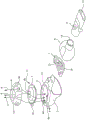
Fig. 1 is a prior art nebulizer showing the basic structural elements of a prior art design for delivering an atomized aqueous solution to a patient by inhalation.
Fig. 2 is an exploded view of the improved nebulizer of the invention showing an alternative method of establishing a vent channel to maintain ambient pressure within a drug cup reservoir during nebulization of an aerosol solution, as well as the expansion volume option of an aerosol mixing chamber. Fig. 2A is a detailed view of the increased internal volume of the aerosol chamber of the greater than L configuration.
Fig. 3 is another view showing the improved nebulizer of the invention operably coupled to an enlarged aerosol mixing chamber having a cup reservoir of an aerosol generator disposed therebetween. Fig. 3A is a detailed view of the increased internal volume of the aerosol chamber in an XL configuration.
FIG. 4 is a cross-sectional view of the improved nebulizer of the invention showing the orientation of the headspace in the cup reservoir, the aqueous solution contained in the cup reservoir, the orientation of one embodiment of the drug cap, the interior volume of the XL aerosol mixing chamber adjacent the aerosol generator and the patient mouthpiece.
Fig. 5 is one embodiment of an ampoule or other container designed to fit within a drug cup reservoir and having a vent passage incorporated into the container itself, rather than relying on modifications in the atomizer structure as an alternative method of maintaining ambient pressure during atomization.
Fig. 6 is a schematic diagram of an in-line version of the improved atomizer of the present invention incorporated into a forced air ventilator breathing circuit.
Detailed Description
Pirfenidone, pyridone analogues and deuterated pirfenidone
As also described elsewhere herein, in preferred embodiments, the pyridone analog formulation as described herein comprises pirfenidone (5-methyl-1-phenyl-2- (1H) -pyridone) or deuterated versions or analogs thereof, comprising: 1-phenyl-2- (1H) pyridone, 5-methyl-1- (4-methylphenyl) -2- (1H) -pyridone, 5-methyl-1- (2' -pyridinyl) -2- (1H) pyridone, 6-methyl-1-phenyl-3- (1H) pyridone, 6-methyl-1-phenyl-2- (1H) pyridone, 5-methyl-1-p-tolyl-3- (1H) pyridone, 5-methyl-1-phenyl-3- (1H) pyridone, 5-methyl-1-p-tolyl-2- (1H) pyridone, 5-ethyl-1-phenyl-3- (1H) pyridone, and 4-methyl-1-phenyl-3- (1H) pyridone, and including deuterated forms of the foregoing.
Pulmonary and regional diseases
Many lung diseases, such as interstitial lung diseases (ILD; and subclasses thereof), fibrotic indications of the lung, kidney, heart, and inflammatory and fibrotic indications caused by viral infections and other pathologies, whether primary or due to specific molecular mechanisms, are currently areas of unmet clinical need, as no specific pharmaceutical intervention has proven to be therapeutic, or different modes of administration of APIs have proven to be ineffective, or have demonstrated such significant drawbacks, such as the potential therapeutic value not realized when pirfenidone is administered orally.
In fibrosis, scarring plays an important healing role after injury. However, after more chronic and or repeated lesions lead to dysfunction, the tissue may gradually scar. In the case of idiopathic pulmonary fibrosis (IPF; and other subclasses of ILD, including chronic fibrotic ILD or progressive phenotypes and ILD associated with systemic sclerosis), respiratory failure may occur if a sufficient proportion of the lungs become scarred. In any case, progressive scarring may be due to repeated occurrence of a series of lesions in different areas of the organ, or failure to stop the repair process after healing of the lesions. In such cases, the scarring process may become uncontrolled and deregulated. In some forms of fibrotic disease, scarring is still confined to a limited area, but in other forms of fibrotic disease, scarring may affect more diffuse and extensive areas, leading to direct or related organ failure.
In epithelial lesions, epithelial cells are triggered to release several pro-inflammatory and pro-fibrotic mediators, including interleukin-1 beta, potent fibroblast growth factor transforming growth factor-beta (TGF-beta), tumor Necrosis Factor (TNF), platelet-derived growth factor (PDGF), endothelin, other cytokines, metalloproteinases, and coagulation mediator tissue factor. Importantly, triggered epithelial cells become susceptible to apoptosis and, along with the apparent inability to restore epithelial cell layers, are the most fundamental abnormalities in fibrotic diseases.
In conditions such as diseases, physiological responses characterized by control of pro-inflammatory and pro-fibrotic factors with pyridone analogs such as pirfenidone may be beneficial in the treatment or prevention of fibrosis, inflammation, or graft rejection. Therapeutic strategies utilizing such pyridone analogs and/or pirfenidone effects in these and other indications are contemplated herein.
The mechanism of action of pyridone analogues such as pirfenidone regulates the production of cytokines and growth factors. These effects may be caused directly by direct exposure to pirfenidone or may reflect secondary effects associated with modulation of individual molecular targets. In either case, the modulation of cytokines, growth factors and oxidative stress markers by pirfenidone demonstrated that the in vivo observed anti-fibrotic effects were associated with the modulation of ongoing fibrosis-associated channels and provided support for the observed anti-fibrotic effects.
For all of these diseases, as well as for the conditions described below, improved aerosol delivery of the enhanced respirable delivery dose of API by the improved nebulizer designs disclosed herein improves the therapeutic efficacy of the compound and the overall treatment of the disease.
Interstitial lung disease, pulmonary fibrosis and graft rejection
Interstitial Lung Disease (ILD) includes a variety of fibrotic indications including, for example, idiopathic Pulmonary Fibrosis (IPF), chronic fibrotic ILD, or progressive phenotypes, and ILD associated with systemic sclerosis. These and other pulmonary fibrosis indications are referred to herein as pulmonary fibrosis. Pulmonary fibrosis may be treated with pyridone analogues or pirfenidone. In some embodiments, the subject is mechanically ventilated. This group of disorders is characterized by scarring of the deep lung tissue, resulting in shortness of breath and loss of functional alveoli, limiting oxygen exchange. Etiology includes inhalation of inorganic and organic dust, gases, fumes and vapors, use of drugs, exposure to radiation, and development of conditions such as hypersensitivity pneumonitis, coal dust lung, radiation, chemotherapy, transplant rejection, silicosis, cotton dust disease, and genetic factors.
Exemplary fibrotic lung diseases treated or prevented using the methods described herein include, but are not limited to, idiopathic pulmonary fibrosis, chronic fibrotic ILD or progressive phenotype, ILD associated with systemic sclerosis, secondary to Quan Yin fibrillating alveolitis, radiation fibrosis, sarcoidosis, scleroderma, chronic asthma, silicosis, asbestos-induced pulmonary or pleural fibrosis, acute lung injury, and acute respiratory distress (including bacterial pneumonia-induced, wound-induced, viral pneumonia-induced, ventilator-induced, non-pulmonary sepsis-induced, and inhalation-induced).
In some embodiments, the subject is a subject mechanically ventilated and connected to an in-line nebulizer operating according to the design parameters disclosed herein.
Diseases of the lung
A method for treating or preventing progression of an extrapulmonary disease, the method comprising administering a pyridone analog or pirfenidone to the mid-to-lower respiratory tract of a subject suffering from or suspected of suffering from an extrapulmonary disease by oral inhalation of an aerosol comprising the pyridone analog or pirfenidone for pulmonary vascular absorption and delivery to the extrapulmonary diseased tissue. In some embodiments, the extrapulmonary disease is cardiac fibrosis. By way of non-limiting example, the term "cardiac fibrosis" relates to remodeling associated with or caused by viral or bacterial infection, surgery, duchenne muscular dystrophy (duchenne muscular dystrophy), radiation therapy, chemotherapy, graft rejection and chronic hypertension, wherein myocyte hypertrophy and fibrosis are involved, and increased and uneven deposition of extracellular matrix proteins occurs. Fibrosis occurs in many models of hypertension, resulting in increased diastolic stiffness, reduced cardiac function, increased risk of arrhythmia, and impaired cardiovascular function. In some embodiments, the extrapulmonary disease is heart transplant rejection. In some embodiments, the subject is a mechanically ventilated subject.
A method for treating or preventing progression of an extrapulmonary disease, the method comprising administering a pyridone analog or pirfenidone to the mid-to-lower respiratory tract of a subject suffering from or suspected of suffering from an extrapulmonary disease by oral inhalation of an aerosol comprising the pyridone analog or pirfenidone for pulmonary vascular absorption and delivery to extrapulmonary diseased tissue for the purpose of improved dosage provided by improvement of structural and functional performance of a nebulizer as described herein. In some embodiments, the extrapulmonary disease is renal fibrosis. In some embodiments, the extrapulmonary disease is renal transplant rejection. By way of non-limiting example, the term "renal fibrosis" relates to remodeling associated with or caused by chronic infection, obstruction of ureters by stones, malignant hypertension, radiation therapy, graft rejection, severe diabetic conditions, or chronic exposure to heavy metals. In some embodiments, renal fibrosis is well correlated with an overall loss of renal function. In some embodiments, the subject is a mechanically ventilated subject.
Liquid atomizer
The amount of drug placed in the nebulizer prior to administration to a mammal is often referred to as the "nominal dose" or "loading dose". The volume of solution containing a nominal dose is referred to as the "fill volume". Smaller droplet sizes or slow inhalation rates allow deep lung deposition. Depending on the indication, e.g. mid-lung and/or alveolar deposition for pulmonary fibrosis and systemic delivery, the present invention may expect both mid-lung and alveolar deposition.
The improved atomizer design of the present invention is applicable to any sealing system in which a negative pressure is created on the liquid side of the device when the aqueous solution containing the API is converted to an aerosol. Potential nebulizer designs include ultrasonic nebulizers, pulsed film nebulizers, vibrating mesh or plate nebulizers with multiple holes, non-vibrating mesh nebulizers (Omron ) And a nebulizer comprising a vibration generator and a water chamber (e.g.)>
 ). Commercially available atomizers suitable for use in the present invention may comprise +>
 Pro and->
 Go、
Go、 Solo、
Solo、 Solo/Idehaler combinations, < >>
 Solo or Go->
 Combination, philips InnoSpire Go, eFlow and eFlow +.>
 (PARI,GmbH)、Vectura
 (Omron Healthcare, inc.), (Omron Healthcare, inc.)>
 (Aerogen (Inc., mountain View, calif.)), omron->
 (Ohio healthcare Co., ltd.), omron->
 (ohm Dragon healthcare Co.), ->
 6610 (Lumiscope (The Lumiscope Company, inc.)), airsep +.>
 (Ai Shepu company (AirSep Corporation)),>
 (Medical 02 Industrial sa merica), I-neb manufactured by Philips, inc.
Exemplary ultrasonic nebulizers suitable for providing drug delivery as described herein may include UltraAir, siemens (Siemens) super nebulizer 145, kang Puai (CompAir), pulmosonic, scout, 5003 ultrasonic Neb, 5110 ultrasonic Neb, 5004 desktop ultrasonic nebulizer, mystique ultrasonic, lumiscope ultrasonic nebulizer, madder health (medisan) ultrasonic nebulizer, microstat ultrasonic nebulizer. Other atomizers used herein include 5000 electromagnetic Neb, 5001 electromagnetic Neb 5002 rotary piston Neb, lumineb I piston atomizer 5500, aeroneb portable atomizer system, aerode inhaler. Exemplary nebulizers comprising a vibrating mesh or plate with multiple orifices were developed by r.dhand in new nebulizer technologies-aerosol generation by using a vibrating mesh or plate with multiple orifices (New Nebuliser Technology-Aerosol Generation by Using a Vibrating Mesh or Plate with Multiple Apertures), "Long-healthcare strategy (Long-TermHealthcare Strategies), (7 month of 2003), pages 1-4 and" Respiratory Care (Care), 47:1406-1416 (2002), the entire disclosure of each of which is hereby incorporated by reference.
Additional atomizers suitable for use with the presently described invention include atomizers comprising a vibration generator and a water chamber. Such atomizers are commercially marketed as, for example, PARI eFlow and are described in U.S. patent nos. 8,511,581, 7,458,372, 9,061,303, 8,387,895, 9,168,556, 6,983,747, 6,962,151, 5,518,179, 5,261,601 and 5,152,456, 7,316,067 and U.S. publication nos. 2016/0310681, 2018/0221906, each of which is specifically incorporated herein by reference. Other commercially available vibrating mesh devices include the Breelib breath activated vibrating mesh nebulizer from Vetura, deep from HCmed, a vibrating mesh device, Vibrating mesh atomizer, PARI eFlow ≡>
 Retrofitting, NBM-2 from Simzo, airPro series, aeroCentre series, aeroGo series and +.Foundation from Feellife>
 Series atomizers, NEB-800 of Michael doctor (Microlife), mobi net of NB-810B, apex of Honsun, M-Neb flow+, prodigy of Salvia->
 Kangbao Co (Health)&Life) Neplus (NE-SM 1) of HL100A, KTMed, WN-114 of B.well, digio2 +.>
 B of BabybelleBU01, PARI's Velox, taiDoc's TD-7001, K-jump's KN-9100, medpack's NE-SM1 and OK Biotech's DocSpray hand-held vibrating mesh atomizer. The research device contained Afina (Philips, and product concept stage device) from Tekceleo.
A high efficiency liquid nebulizer is an inhalation device suitable for delivering a large portion of a loaded dose to a patient. Some high efficiency liquid atomizers utilize microperforated films as aerosol generators. In some embodiments, the high efficiency liquid atomizer further utilizes one or more actively or passively vibrating microperforated films as an aerosol generator. In some embodiments, the high efficiency liquid atomizer houses one or more oscillating or pulsating membranes as an aerosol generator. In some embodiments, the high efficiency liquid atomizer houses a vibrating mesh or plate having a plurality of apertures, and optionally houses a vibration generator having an aerosol mixing chamber. In some such embodiments, an aerosol mixing chamber is used to collect (or fractionate) aerosol from an aerosol generator. In some embodiments, the one-way inhalation valve is also used to allow auxiliary ambient air to flow into the aerosol mixing chamber during the inhalation phase and to close to prevent aerosol from escaping from the aerosol mixing chamber during the exhalation phase.
The one-way inhalation valve or vent passageway opening to ambient air on the aerosol side of the nebulizer may be placed in the housing of the aerosol mixing chamber or near the liquid side of the device with a dedicated passageway from the vent passageway opening to the aerosol mixing chamber, see for example USP 8,387,895.
The one-way exhalation valve is disposed in or near a mouthpiece mounted on the outlet of the aerosol mixing chamber and through which the patient inhales aerosol from the aerosol mixing chamber. In some embodiments, the high efficiency liquid atomizer is continuously operated and may be controlled by patient-actuated circuitry that initiates and/or terminates operation of the aerosol generator. In some embodiments, the high efficiency liquid atomizer operation is breath actuated.
In some embodiments, the high efficiency liquid atomizer houses a vibrating micro-perforated membrane of a conical nozzle that can create a plume of droplets for a large volume of liquid without the need for compressed gas. In these embodiments, the solution in the micro-perforated membrane nebulizer is present in the drug cup reservoir, allowing contact with the aerosol generating membrane, which is open to air on opposite sides. The membrane is penetrated by a large number of tiny nozzle orifices. An aerosol is generated when alternating acoustic pressure in the solution forms in the vicinity of the membrane, causing fluid on the liquid side of the membrane to be ejected through the nozzle as uniformly sized droplets.
In some embodiments, the high efficiency liquid atomizer uses a passive nozzle membrane and a separate piezoelectric transducer in contact with the solution present in the drug cup reservoir. In contrast, some high efficiency liquid atomizers employ an active nozzle membrane that utilizes acoustic pressure in the atomizer to produce very fine droplets of solution by high frequency vibration of the nozzle membrane.
Some high efficiency liquid atomizers house a resonant system. In some such high efficiency liquid atomizers, the membrane is driven by a frequency for which the amplitude of the vibration motion at the center of the membrane is particularly large, resulting in a focused sound pressure near the nozzle; the resonant frequency may be about 100kHz. The flexible mounting serves to keep unnecessary vibration energy losses of the mechanical environment of the atomizing head to a minimum. In some embodiments, the diaphragm of the high efficiency liquid atomizer may be made of nickel palladium alloy by electroforming.
In some embodiments, the high efficiency liquid nebulizer (i) achieves lung deposition of at least about 30%, at least about 35%, at least about 40% based on administration of a nominal dose of the pyridone analog or pirfenidone compound to the mammal.
In some embodiments, the high efficiency liquid atomizer (ii) provides a Geometric Standard Deviation (GSD) of the spray droplet size distribution of the solution applied with the high efficiency liquid atomizer of from about 1.0 to about 2.5, from about 1.2 to about 2.5, from about 1.3 to about 2.0, at least about 1.4 to about 1.9, at least about 1.5 to about 1.9, about 1.5, about 1.7, or about 1.9.
In some embodiments, the high efficiency liquid atomizer (iii) provides a Mass Median Aerodynamic Diameter (MMAD) of droplet size of the solution sprayed with the high efficiency liquid atomizer of less than about 5 μm, about 1 μm to about 5 μm. In some embodiments, the high efficiency liquid atomizer (iii) provides a Volume Median Diameter (VMD) of less than about 5 μm, about 3 μm to about 5 μm. In some embodiments, the high efficiency liquid atomizer (iii) provides a Volume Median Diameter (VMD) of less than about 5 μm, about 3 μm to about 5 μm.
In some embodiments, the high efficiency liquid atomizer (iv) provides a fine droplet fraction (fpf=% < 5 microns) of at least about 45% and up to 75% of aerosol droplets ejected from the high efficiency atomizer.


a. Data from laser diffraction
b. Data from cascade impact
In some embodiments, the high efficiency liquid atomizer (v) provides a volumetric output rate of at least 0.38 ml/min. In some embodiments, the high efficiency liquid atomizer (vi) delivers at least about 50% of the fill volume to the mammal.
In some embodiments, the high-efficiency liquid nebulizer provides an RDD of at least about 22% of the nominal dose and provides a total daily dose of greater than 25mg of pirfenidone by a multiple dosing regimen that may require the use of at least 0.5ml of pirfenidone at a concentration of greater than 4mg/ml, preferably less than 19mg/ml, per loaded dose at a respirable delivery dose output rate of greater than 2.8 milligrams per minute in a single day.
Atomizer optimization
In a sealed reservoir nebulizer, the act of loading the drug into the drug cup reservoir and closing the drug cup reservoir creates a negative pressure within the closed drug cup reservoir—either upon placement of the cap or upon a decrease in the fluid level in the reservoir. The conversion of the loaded dose volume of the API aqueous solution in the closed cup reservoir to aerosol creates a gradually increasing negative pressure within the closed system, thereby creating a negative pressure on the liquid side of the nebulizer, defined by the interior volume of the reservoir and the barrier formed by the aerosol generator. In each case, negative pressure in the cup reservoir slows the output rate and may negatively impact the aerosol droplet size produced. This effect is further increased in existing nebulizer designs where there is a limited dead volume of the drug cup reservoir prior to nebulization.
The structure of the improved nebulizer comprises a drug cup reservoir capable of containing a nominal loading dose or filling dose of an API containing a therapeutic dose, and leaving a headspace between the liquid volume of the aqueous formulation of the API and the interior of the device housing, a drug cup reservoir cap or shield formed from an API container, a vibrating mesh aerosol generator, and optionally an aerosol mixing chamber in which freshly generated aerosol resides until inhaled, a one-way inhalation valve, a mouthpiece and a one-way exhalation valve, the structure of the nebulizer being modified to maintain ambient pressure in the reservoir by connecting the headspace of the reservoir to ambient pressure conditions. The structural modification that allows for the maintenance of atmospheric pressure inside the drug cup reservoir after the addition of the drug to be aerosolized has several structural options that all perform the function of establishing a vent channel from the headspace of the reservoir to ambient conditions after loading the API dose and the reservoir is operatively sealed, and before operation of the nebulizer and during conversion of the solution into aerosol to produce the improved aerosol parameters as described herein. The cup reservoir or cup reservoir cap also allows for discrete steps of maintaining the cup reservoir atmospheric pressure after dose loading and throughout aerosolization and dose administration. In addition, nebulizer aerosol mixing chamber volumes have been optimized to minimize newly generated aerosol droplet collisions, droplet growth, and/or condensation and deposition during exhalation, prior to inhalation, or during inhalation. In cases where saline is unpredictable, the individual effect of these features on the administration of pirfenidone formulation is to increase the device output rate of respirable aerosol droplets less than 5 microns in diameter per unit time ejected from the device, thereby increasing the respirable dose delivery rate.
According to human models, these features increase Cmax and AUC of pirfenidone to improve treatment or prevention of various diseases including diseases associated with the lung, heart and kidney, including fibrosis, inflammatory conditions and transplant rejection, wherein the minimum threshold for aerosol delivery of pirfenidone achieves therapeutic effects. Combining a therapeutically effective respirable dose delivery rate through nebulized pirfenidone solution with the novel structural features of a nebulizer as described below provides a synergistic effect between a pirfenidone solution based on a specific formulation for aerosol administration and a performance output rate criteria comprising respirable aerosol droplets with idealized particle physical parameters for therapeutic delivery of a drug product.
Nebulizer-drug combination
In one aspect, the invention described herein is a drug device combination comprising an improved nebulizer and an API formulated and packaged to a defined API volume and concentration such that a specific therapeutic dose of aqueous solution results from the use of the improved nebulizer with a solution for nebulized aerosol administration. In the example of pirfenidone, the aqueous solution comprises: water; pirfenidone or pyridone analogues, the aqueous solution comprising deuterated pirfenidone having a concentration of osmotic ionic species and osmotic pressure-regulating component, which may be the same species, of about 4.0-19.0 mg/ml to produce a final solution in the device reservoir. The aqueous pirfenidone solution also has a range of selected parameters tailored to maximize the therapeutic potential of the pirfenidone solution delivered by the modified nebulizer, the aqueous pirfenidone solution comprising more than one inorganic salt selected from the group consisting of sodium chloride, magnesium chloride, calcium chloride, sodium bromide, magnesium bromide, and calcium bromide at a concentration of between 30mM and about 450 mM. In some embodiments, the aqueous solution comprises more than one buffer selected from one or more of the following: lysine, glycine, acetylcysteine, glutamine, acetate, borate, citrate, fumarate, malate, maleate, sulfate, phosphate or Tris. In some embodiments, the pH of the aqueous solution is about pH 3.0 to about pH 8.5. In some embodiments, the aqueous solution has an osmolality of about 50mOsmol/kg to about 1000mOsmol/kg. In some embodiments, the buffer concentration in the aqueous solution is about 0.01mM to about 50mM. In some embodiments, the solution further comprises one or more additional ingredients selected from the group consisting of: tonicity agents, taste masking agents, sweeteners, wetting agents, chelating agents, antioxidants, inorganic salts and buffers. In some embodiments, the solution further comprises an additional ingredient selected from taste masking/sweetener and inorganic salts. In some embodiments, the taste masking/sweetener is saccharin or a salt thereof. In some embodiments, a dosage volume of about 0.5mL to about 10mL of the aqueous solutions described herein is described herein. In some embodiments, the concentration of the aqueous pirfenidone solutions described herein is about 4mg/mL to about 19mg/mL. In some embodiments, described herein are devices loaded with an aqueous solution containing 2mg to about 152mg pirfenidone. In some embodiments, described herein are aqueous device loading doses containing about 2mg to about 152mg of pirfenidone delivered in less than 15 minutes. In some embodiments, described herein are aqueous device loading doses containing about 2mg to about 1 mg of pirfenidone delivered in less than 15 minutes, providing at least about 22% of the pirfenidone loading dose in aerosol droplets of less than 5 microns. In some embodiments, described herein are aqueous device loading doses containing about 6.25mg to about 125mg of pirfenidone delivered in less than 15 minutes, thereby providing at least about 22% of the pirfenidone loading dose in the aerosol droplets delivered sequentially of less than 5 microns, such respirable delivery doses being delivered at a rate of at least 2.8 milligrams of pirfenidone per minute.
In some embodiments, described herein is a kit comprising: a unit dose of an aqueous solution of pirfenidone or a pyridone analogue comprising deuterated pirfenidone as described herein in a container suitable for use in a modified nebulizer and optionally containing a nebulizer with instructions for delivering the dose provided by the kit. Separately, the kit may provide specific instructions for use of the drug device combination as part of a therapeutic regimen, including instructions for use, cleaning and/or maintenance specific to the nebulizer described herein.
In order to maximize the efficacy of inhaled pirfenidone or pyridone analogues, shorter inhalation administration times may be desirable. Local delivery of the inhaled mass will be eliminated from its deposition site at a rate defined by its physicochemical characteristics and the relevant characteristics of the target tissue of the inhaled dose deposited therein. As in the case of pirfenidone and pyridone analogues, some substances are rapidly eliminated from the target tissue. To compensate, it is necessary to increase the delivery rate beyond eliminating and increasing the local concentration of inhaled substances. More specifically, for pirfenidone and pyridone analogues, whose delivery concentration is related to activity, increasing the respirable dose delivery rate (the rate of delivery of inhaled droplets less than 5 microns in diameter to the target tissue) will eliminate the equilibrium deviation, thereby positively affecting the therapeutic or prophylactic effect; indeed, the faster the respirable dose is administered, the greater the Cmax and AUC concentrations achieved at the target site. The respirable dose delivery rate can be increased by increasing the number of aerosol droplets less than 5 microns. In some embodiments, the respirable dose delivery rate may be increased by increasing the nebulizer output rate (increasing aerosol production per unit time). In some embodiments, the respirable dose delivery rate may be increased by combining an increased number of droplets less than 5 microns with an increased nebulizer output rate.
In one embodiment, the respirable dose may be increased by reducing the perforated membrane pore size within the mesh aerosol generator. However, reducing the aperture may also reduce the nebulizer aerosol output rate. Alternatively, compensation may be performed by increasing the volume of the aerosol mixing chamber to increase the number of compartments containing freshly generated aerosol. The increased volume of the mixing chamber reduces inter-aerosol droplet collisions, droplet impingement of the aerosol droplets on the aerosol mixing chamber wall and/or condensation of the aerosol during the exhalation phase, prior to inhalation or during inhalation. The larger internal volume also allows more aerosol to accumulate in the aerosol mixing chamber during the exhalation phase. In the present invention, a liquid atomizer mesh aerosol generator contains thousands of small holes in a perforated membrane designed to produce aerosol droplets having a volume median diameter of less than 5 microns.
In some embodiments, perforated membrane pore sizes may be produced within a mesh aerosol generator to produce aerosol VMDs greater than about 3 microns and less than about 5 microns. In some embodiments, the cup reservoir capacity is greater than 4.0ml, 6.0ml, 8.0ml, and preferably less than 14ml. The dead volume of the cup reservoir after the additive amount of solution is less than about 10mL, less than about 8mL, less than about 6mL, less than about 4mL, less than about 2mL, less than about 1mL, less than about 0.5mL.
In some embodiments, the nebulizer may continuously produce an aerosol. In other embodiments, the generation of nebulizer aerosols may be breath-actuated. In some embodiments, the atomizer may house all of the components required for atomization in a single unit. In other embodiments, the atomizer may be in a wired or wireless manner, e.g More than one unit connected accommodates the components required for atomization.
Achieving beneficial drug concentrations in the lung or downstream target tissue depends on two key factors: the rate at which inhaled droplets deposit in the lungs and the rate at which the drug within the deposited droplets is eliminated from the lungs. Increasing the aerosol output rate while maintaining a respirable dose (the amount of drug containing aerosol droplets less than 5 microns in diameter) can shift the deposited drug out of equilibrium, resulting in higher deposited drug levels and subsequent increases in Cmax and AUC. This is critical for pirfenidone and pyridone analogues, the mechanism of which depends on achieving increased local drug concentrations in the target tissue.
In some embodiments, a pirfenidone compound formulation as disclosed herein is placed in a preferred vibrating mesh nebulizer configuration and loaded with about 10mg to about 100mg of pirfenidone in a dosage solution of about 0.5mL to about 10 mL.
In some embodiments, the respirable delivered dose of each pyridone analog or pirfenidone is greater than about 0.5mg, greater than about 4mg, greater than about 12.5mg, greater than about 22mg, greater than about 38mg, greater than about 50mg. For 4mg/mL pirfenidone aqueous solutions, the respirable delivery dose is delivered at a rate of greater than about 0.9 milligrams per minute. For 12.5mg/mL pirfenidone aqueous solution, the respirable delivery dose is delivered at a rate of greater than about 2.8 mg/min. For 19mg/mL pirfenidone aqueous solution, the respirable delivery dose is delivered at a rate of greater than about 4.3 milligrams per minute.
In some embodiments, the pyridone analog or pirfenidone may be administered in a preferred vibrating mesh nebulizer configuration in less than about 25 minutes, less than about 20 minutes, less than about 18 minutes, less than about 16 minutes, less than about 14 minutes, less than about 12 minutes, less than about 10 minutes, less than about 8 minutes, less than about 6 minutes, less than about 4 minutes, less than about 2 minutes, less than about 1 minute, less than five breaths, less than four breaths, less than three breaths, less than two breaths, or one breath.
In some embodiments, the pyridone analog or pirfenidone may be administered in a preferred vibrating mesh nebulizer configuration to deliver the lung intraepithelial fluid at a concentration of greater than 10 micrograms/ml/min, greater than 5 micrograms/ml/min, greater than 2.5 micrograms/ml/min.
In some embodiments, the pyridone analog or pirfenidone may be administered in a preferred vibrating mesh nebulizer configuration to deliver the lung intraepithelial fluid with an exposure of greater than 0.15 mg-hr/l/min, greater than 0.10 mg-hr/l/min, greater than 0.05 mg-hr/l/min.
In one aspect, described herein is a lung intraepithelial fluid AUC for achieving pyridone analogs or pirfenidone 0-24 In a method of delivering a pyridone analog or pirfenidone using an equivalent nebulizer loaded with the same dose to produce an intraepithelial fluid AUC 0-24 At least 1.1-fold, at least 1.2-fold, at least 1.3-fold, at least 1.4-fold, at least 1.5-fold to at least 3-fold, but still lacks the optimization features described herein. In one aspect, described herein is a method of achieving Cmax of lung intraepithelial fluid of a pyridone analog or pirfenidone using an equivalent nebulizer loaded with the same doseDelivery of a pyridone analog or pirfenidone produces at least 1.1-fold, at least 1.2-fold, at least 1.3-fold, at least 1.4-fold, at least 1.5-fold to about 3-fold of intraepithelial fluid Cmax, but still lacks the optimization features described herein.
In some embodiments, a continuous dosing regimen refers to administration of a pyridone analog or pirfenidone at regular intervals without any drug release from a particular therapeutic agent. In some other embodiments, a continuous dosing regimen refers to administration of a pyridone analog or pirfenidone in alternating drug administration cycles, followed by a drug holiday (e.g., a batch period) from the pyridone analog or pirfenidone. For example, in some embodiments, the pyridone analog or pirfenidone is administered once a day, twice a day, three times a day, once a week, twice a week, three times a week, four times a week, five times a week, six times a week, seven times a week, once every other day, once every other two days, once every other three days, daily for one week, then one week without the pyridone analog or pirfenidone, daily for two weeks, then one week or two weeks without the pyridone analog or pirfenidone, daily for three weeks, then one week, two weeks or three weeks without the pyridone analog or pirfenidone, daily for four weeks, then one week, two weeks, three weeks or four weeks without the pyridone analog or pirfenidone, once a week with the therapeutic agent, then one week without the pyridone analog or pirfenidone, or the therapeutic agent, or once two weeks with the two weeks without the pyridone analog or pirfenidone.
In some embodiments, the amount of repeated high Cmax administration that provides more regular exposure to a pyridone analog or pirfenidone administered to a human depends on various factors such as, but not limited to, the condition and severity of the disease or condition, and the characteristics of the human (e.g., body weight), as well as the pyridone analog or pirfenidone administered (if applicable).
All U.S. patents, U.S. patent application publications, U.S. patent applications, foreign patents, foreign patent applications, and non-patent publications mentioned in this specification are incorporated herein by reference, in their entirety.
Examples
Example 1 atomizer and aerosol Performance optimization
To measure the effect of aerosol mixing chamber volumes (referred to herein as L and XL) and to maintain atmospheric pressure during nebulization and administration of therapeutic doses to patients using the nebulizer designs described herein, the following data was collected to measure and demonstrate performance improvements as opposed to allowing for increased negative pressure to be generated as the volume of the reservoir headspace above the loading dose volume increases over time during nebulization creating a negative pressure bias in the pirfenidone reservoir.
As an initial analysis, the sprayed aerosol saline and pirfenidone aqueous solution formulation droplet size over time was measured using a Helos, neopatec (Sympatec) laser under partially simulated respiratory conditions using a comp as 2 respiratory simulator (adult respiratory mode, 500mL tidal volume, 15 breaths/min, 1:1 inhalation: exhalation ratio). Briefly, twelve study PARI with a single set of 6 (six) 35 class aerosol heads (6 heads total; table 1)  Nebulizers (with 6L and 6XL aerosol mixing chambers) were used in both L (about 49cc volume aerosol mixing chamber) and XL (about 98cc volume aerosol mixing chamber) configurations and tested in triplicate with 8mL pirfenidone aqueous cup reservoirs under atmospheric conditions (vented) and allowing negative pressure to be generated (non-vented). The following exemplary replicas were performed: A. head 1/L/ventilated, b. head 1/L/non-ventilated, c. head 1/XL/ventilated, d. head 1/XL/non-ventilated, and repeated in the following order: A. b, C, D, A, B, C, D, A, B, C, D. The results are shown in table 2.
TABLE 1 saline-aerosol characteristics of saline-aerosol head alone

Vmd: volume median diameter; gsd: geometric standard deviation; TOR: total output rate based on average output
In this analysis, the respirable aerosol droplet output rate of the saline and pirfenidone formulation was determined by multiplying the respirable fraction (RF; percentage aerosol droplet ejection less than 5 microns in diameter in 20 second increments) by the total output rate (TOR; calculated by dividing the total nebulizer weight loss by the nebulization duration). The results are shown in tables 2 and 3. Saline was prepared as 150mM sodium chloride in water, while the pirfenidone formulation was 5mM citrate buffer, pH 6.0, containing 12.5mg/mL pirfenidone, and water containing 150mM sodium chloride and 0.75mM sodium saccharin. For vented "L", unvented "L", vented "XL" and unvented "XL", the duration of nebulization of 8mL of saline was 8.6 minutes, 12.6 minutes, 8.5 minutes and 12.0 minutes, respectively. For vented "L", unvented "L", vented "XL" and unvented "XL", the duration of the nebulization 8mLAP01 was 8.4 minutes, 12.3 minutes, 8.3 minutes and 12.4 minutes, respectively.
TABLE 2 saline-Mitigation cup pressure, aerosol mixing Chamber volume, and the benefit of the breathable aerosol droplet output Rate percentage of the two characteristics combined

a.V: ventilated (with the cup maintained at atmospheric pressure), NV: non-venting (closed system medicine cup); b. a respirable aerosol droplet output rate (grams of aerosol droplets emitted < 5 microns per minute) during 2 minute nebulization increments; c. benefits are measured as a percentage increase between the drug cup pressure (vented versus non-vented in either the "L" or "XL" configuration), aerosol mixing chamber volume (L versus "XL" in either the vented or non-vented configuration), and the combined benefits of the vented "XL" device configuration as compared to the non-vented "L" device configuration. d. Ventilated "L" versus non-ventilated "L"; e. ventilated "L" versus ventilated "XL"; f. ventilated "XL" versus non-ventilated "XL"; g. non-vented "L" versus non-vented "XL"; h. ventilated "XL" versus non-ventilated "L".
The saline data presented in table 2 shows that venting the drug cup reservoir while aerosolizing the saline during early administration has a small negative benefit (about-1.5% in the "L" configuration and about-1% in the "XL" configuration) to the respirable aerosol droplet output rate (grams of aerosol droplets ejected per minute < 5 microns), and that this negative effect increases slightly near the end of administration (about-6.4% in the "L" configuration and about-5.5% in the "XL" configuration). The data also shows that aerosol mixing chamber volumes have small positive benefits. Combining these two device elements shows a homogenization effect, wherein the observed positive benefit for increasing the volume of the aerosol mixing chamber mitigates the small negative effects associated with ventilating the drug cup (about +2.3% in the early stage of saline dose administration and-2.1% in the later stage). Based on this saline data, there is no reasonable reason for modifying the housing of the nebulizer to affect the pressure profile over time, or for modifying the size of the aerosol mixing chamber to improve the delivery parameters of the aerosol formed from the pirfenidone aqueous solution, nor is there any reasonable reason that such modification may lead to a therapeutically effective result.
Table 3-benefits of moderating cup pressure, aerosol mixing chamber volume, and the percentage of breathable aerosol droplet output rate of pirfenidone aqueous solution combined with two features


a.V: ventilated (with the cup maintained at atmospheric pressure), NV: non-venting (closed system medicine cup); b. a respirable aerosol droplet output rate (grams of aerosol droplets emitted < 5 microns per minute) during 2 minute nebulization increments; c. benefits are measured as a percentage increase between the drug cup pressure (vented versus non-vented in either the "L" or "XL" configuration), aerosol mixing chamber volume (L versus "XL" in either the vented or non-vented configuration), and the combined benefits of the vented "XL" device configuration as compared to the non-vented "L" device configuration; d. ventilated "L" versus non-ventilated "L"; e. ventilated "L" versus ventilated "XL"; f. ventilated "XL" versus non-ventilated "XL"; g. non-vented "L" versus non-vented "XL"; h. ventilated "XL" versus non-ventilated "L".
Unlike the observed saline, the data for pirfenidone therapeutic aqueous solutions listed in table 3 demonstrate that venting the drug cup reservoir has a great positive benefit for the respirable aerosol droplet output rate ("about +19.4% in the" L "configuration and about +23.8% in the" XL "configuration) and a slight decrease at the end of administration (about +17.5% in the" L "configuration and about +17% in the" XL "configuration). Interestingly, the aerosol mixing chamber volume showed a slight negative benefit (about-2% to-5.5% benefit regardless of the cup pressure in all device configurations) for the respirable aerosol droplet output rate. Combining these two device elements shows a homogenization effect, wherein the positive effect of venting the cup reservoir alleviates the small negative effects associated with increasing the cup reservoir size (about +17% in the early stage of pirfenidone dose administration and down to +12.6% in the later stage).
In these initial measurements, using laser diffraction and weight calculations to determine the amount of respirable aerosol droplets per unit time, the combined data of tables 2 and 3 show that there is a great positive benefit in venting the nebulizer cup reservoir when nebulizing therapeutic amounts of pirfenidone aqueous solution, and a negative benefit when nebulizing saline. Similarly, while increasing the aerosol mixing chamber volume has a small negative impact on the therapeutic pirfenidone solution, venting the reservoir alone or in combination with increasing the aerosol mixing chamber volume increases the respirable aerosol droplet output rate of the pirfenidone therapeutic solution, which is much higher than the rate predicted by saline.
For a more clinically relevant comparison of aerosol delivery parameters of pirfenidone in solution in a second analysis, the respirable delivered dose (RDD; amount of pirfenidone deposited from aerosol droplets less than 5 microns in diameter) was measured during a respiratory simulation (adult respiratory mode, 500mL tidal volume, 15 breaths/min, 1:1 inhalation: exhalation ratio) using a Compas 2 respiratory simulator as shown below. Briefly, twelve studies with a single set of 6 (six) 35-class aerosol heads (6 heads total; table 1)  Nebulizers (with 6L and 6XL aerosol mixing chambers) were used in both (about 49cc volume) and XL (about 98cc volume) aerosol mixing chamber configurations and were tested in duplicate with 8mL pirfenidone aqueous cup reservoirs under atmospheric conditions (vented) and allowing negative pressure to be generated during nebulization (unvented). An 8mL dose (12.5 mg/mL aqueous pirfenidone) was loaded into the cup reservoir and aerosolization was initiated. After 2, 4, 6 and 8 minutes of nebulization, the inhalation filters were collected and extracted for pirfenidone quantification using HPLC analysis. After 8 minutes the remaining dose was collected using a final filter. The following exemplary replicas were performed: A. head 1/L/ventilated, b. head 1/L/non-ventilated, c. head 1/XL/ventilated, d. head 1/XL/non-ventilated, and repeated in the following order: A. b, C, D, A, B, C, D. The results are shown in table 4.
TABLE 4 benefits of respiratory delivery of pirfenidone in percent of dose by alleviating cup pressure, aerosol mixing chamber volume, and combination of both features

a.V: vented (holding the drug cup reservoir at atmospheric pressure), NV: non-vented (closed system cup reservoir); b. respirable delivered dose (RDD; mg of pirfenidone inhaled in aerosol droplets < 5 microns) during 2 minutes of simulated inhalation aerosol increment; c. benefits are measured as a percentage increase between the drug cup pressure (vented versus non-vented in either the "L" or "XL" configuration), aerosol mixing chamber volume (L versus "XL" in either the vented or non-vented configuration), and the combined benefits of the vented "XL" device configuration as compared to the non-vented "L" device configuration; d. ventilated "L" versus non-ventilated "L"; e. ventilated "L" versus ventilated "XL"; f. ventilated "XL" versus non-ventilated "XL"; g. non-vented "L" versus non-vented "XL"; h. ventilated "XL" versus non-ventilated "L".
Aerosol pirfenidone data presented in table 4 shows that the vented XL device configuration delivered a 27.84mg dose of respirable delivered pirfenidone (3.48 mg/min; respirable aerosol droplet output rate) in 8 minutes, as compared to a non-vented L configuration delivering a 22.22mg dose of respirable delivered pirfenidone (2.78 mg/min; respirable aerosol droplet output rate) in 8 minutes, wherein the rate was increased (positive slope) during administration, as compared to the increase slowing (negative slope) during administration. Furthermore, the benefits of the differentially vented XL aerosol mixing chamber 8 increase over time; this is a benefit of maintaining atmospheric pressure compared to a non-vented configuration. To distinguish the contributions of each component, the aerosol pirfenidone data presented in table 4 shows that venting the cup reservoir 3 only showed little benefit (about +3.9% in the "L" configuration and about +2.3% in the "XL" configuration) during the early stages of administration of the atomized dose of pirfenidone. However, the ventilation benefit increases significantly near the end of administration (to about +19.9% in the "L" configuration and to about +21.2% in the "XL" configuration), indicating that maintaining atmospheric pressure and/or avoiding negative pressure increases that may occur with a decrease in dose volume within the sealed, non-ventilated drug cup reservoir 3 during administration are highly beneficial for pirfenidone administration in the drug device combinations described herein.
The data also shows that it is beneficial to increase the volume of the aerosol mixing chamber 8. As predicted, this benefit is independent of the cup reservoir 3 pressure (in all device configurations, there is a benefit of about +11% to +13% regardless of the cup reservoir 3 configuration). Combining these two device elements demonstrated significant additional benefits (from about +16% to about +35% at the early stage of aerosolized dose administration of pirfenidone aqueous solution). Thus, a larger volume aerosol mixing chamber 8 is included in combination with a vented arrangement, wherein the nebulizer 1 contains various options for a vent channel 4 that measurably improves lung deposition.
Furthermore, the data of table 4 demonstrates that the effect of the larger volume aerosol mixing chamber 8 is separate and independent, but has a synergistic effect with the design of incorporating the vent passage 4 in the structure of the nebulizer or assembly. Thus, the improvements provided by the vented arrangement, independent of the further improvements provided by the enlarged aerosol mixing chamber 8, can be applied to nebulizer designs having a common or smaller aerosol mixing chamber. Furthermore, as the volume of the cup reservoir 3 decreases, the ability to avoid a negative slope in the respirable delivered dose rate is provided by either or both of the vent structure or the internal volume of the aerosol mixing chamber 8 alone, as revealed by the data of table 4. Likewise, the various venting structures of the nebulizer 1 can be readily applied to different concentrations of pirfenidone, different cup reservoir 3 fill volumes, a range of respirable delivered dose rates, respirable delivered total doses, daily respirable delivered dose total output rates described herein.
As mentioned above, one option of the unitary assembly of nebulizer 1 contains an aerosol generator drive circuit that is not controlled by the user, but rather includes an activation system in which the pressure differential created by the patient's breath taken at the nebulizer mouthpiece activates aerosol generator 7 to convert the aqueous solution of pirfenidone into a therapeutic aerosol. In this configuration, the vented structure provides significant advantages as described herein and shown in the data even though the amount of aerosol held in the aerosol mixing chamber during administration is small.
In accordance with the data disclosed herein, preferred device embodiments utilize either or both of the vented drug cup reservoirs to maintain atmospheric pressure throughout the dose aerosolization process and utilize any size of the embodiments greater than L, or the XL aerosol mixing chamber 8 combinations alone to improve performance across each of the drug device combinations as described herein.
Clinical study data indicate that this preferred device example V/XL nebulized 8mL of 12.5mg/mL pirfenidone in water, administered twice daily (100 mg device loading dose; 200mg daily dose) is effective in slowing down to steady lung fibrosis progression. Further, nebulizing 4mL of 12.5mg/mL pirfenidone in water was more effective than the historical placebo once a day dosing (50 mg device loading dose; 50mg daily dose), but less effective than the 200mg daily dose. Considering the data in Table 4, a preferred device embodiment with a combination of vent and larger aerosol mixing chamber (V/XL) provides a total dose of breathable delivery of pirfenidone of about 27.8mg in about 8 minutes from 8mL of 12.5mg/mL aqueous pirfenidone solution. By calculation, this delivers about 3.5mg of breathable pirfenidone per minute from 12.5mg/mL of aqueous pirfenidone. The combination of devices using the non-vented drug cup reservoir 3 and the L aerosol mixing chamber 8 provides a total dose of breathable delivery of pirfenidone of about 22.2mg of pirfenidone in the same duration and same dosing solution. By calculation, this configuration device delivers about 2.8mg of breathable pirfenidone from 12.5mg/mL pirfenidone in water per minute, or about 25% less per unit time than the preferred V/XL embodiment device. Given that pirfenidone activity is concentration dependent, faster delivery is needed to overcome the elimination mechanism and allow higher lung concentrations and activity.
Because the 50mg aqueous pirfenidone solution dose delivered using the loaded preferred embodiment device is effective, although less than 200mg daily device loading dose, it is believed that lower doses may also accommodate effective levels. Based on the data described herein, a fifty percent reduction in daily dose (25 mg) is expected to be ineffective. By calculating and using the preferred V/XL example device, a 25mg device loading dose of 12.5mg/mL pirfenidone in water will provide a respirable delivery dose of about 7mg at a 3.5 mg/min respirable delivery dose rate similar to a 100mg BID (200 mg daily) device loading dose. In general, using the preferred V/XL device embodiment, daily dosage levels are greater than 25mg, wherein pirfenidone is respirably delivered at a dosage of greater than about 7mg and at a rate of greater than 2.8 mg/min.
The above drug device combination theoretically delivers pirfenidone in an amount of up to 12.5mg/mL, although assuming a fifty percent respirable delivered dose, the total delivery rate would be 6.25 mg/min. Clinical data indicate that about 5.625mg per minute is delivered using the above-described drug device combination, although these numbers vary greatly based on external factors. Thus, the improvement in therapeutic administration using the drug device combinations of the present invention can be described as an increased therapeutic value of administration of aerosol pirfenidone at rates between 2.8 mg/min and 6.25 mg/min, with values of about 5.625 mg/min confirmed by clinical trials.
Example 2 human pharmacokinetic modeling
Using the data of example 1, a human pharmacokinetic model was run to compare the minimum effect of the cup reservoir pressure and aerosol mixing chamber volume on the predicted rate of increase of pirfenidone lung tissue and lung intraepithelial fluid (ELF) concentration (mcg/mL of pirfenidone administered by inhalation aerosol per minute) and exposure (mg/l of pirfenidone administered by inhalation aerosol per minute). The results are shown in table 5.
TABLE 5 simulation of the delivery and accumulation rates of pirfenidone in human lung tissue and intraepithelial fluids

a.V: vented (holding the drug cup reservoir at atmospheric pressure), NV: non-vented (closed system cup reservoir); b. pirfenidone respirable delivery rate (mcg/mL or mg-hr/liter pirfenidone nebulized AP01 inhalation aerosol administration added to the ELF or lung tissue per minute); the ELF benefits are measured as a percentage of increased pirfenidone mcg/mL or milligrams-hours/liter added to ELF or lung tissue per minute, combined benefits of nebulized pirfenidone inhalation aerosol administration between the drug cup pressure (vented versus non-vented in either the "L" or "XL" configurations), aerosol mixing chamber volume (either "L" versus "XL" in either the vented or non-vented configurations), and vented "XL" device configurations as compared to the non-vented "L" device configurations; d. lung tissue: simulated pirfenidone deposition into 600g human lung tissue; ELF: simulated pirfenidone deposition into 20mL human epithelial lung fluid; f. ventilated "L" versus non-ventilated "L"; g. ventilated "L" versus ventilated "XL"; h. ventilated "XL" versus non-ventilated "XL"; i. non-vented "L" versus non-vented "XL"; j. ventilated "XL" versus non-ventilated "L".
The simulated pirfenidone pharmacokinetic data presented in table 5 demonstrate that establishing vent channel 4 in the cup reservoir 3 exhibits a significant increase in lung tissue and ELF pirfenidone deposition per unit time ("about +34% to +36% in the" L "configuration and about +29% to +30% in the" XL "configuration), demonstrating that maintaining atmospheric pressure in the cup reservoir 3 during nebulization and inhalation aerosol administration can significantly increase pirfenidone lung deposition per unit time. The data further demonstrate that increasing the volume of the aerosol mixing chamber 8 also significantly increases pirfenidone pulmonary deposition per unit time (about +9% to +10% in the "L" configuration and about +14% to +15% in the "XL" configuration), demonstrating that increasing the volume of the aerosol mixing chamber 8 also significantly increases pirfenidone pulmonary deposition per unit time. Combining these two device elements demonstrated significant additional benefits, with the ELF pirfenidone concentration rate (micrograms/milliliter/minute) and exposure rate (milligrams hours/liter/minute) increased by +49% over the device configuration lacking these features (non-vented "L" configuration). In general, maintaining the atmospheric pressure in the drug cup reservoir 3 throughout the aerosolization and inhalation administration, either alone increasing the volume of the aerosol mixing chamber 8, or when combined together, significantly increases the ELF or lung tissue pirfenidone Cmax or AUC of lung delivery, a key pharmacokinetic property important to therapeutic efficacy.
Example 3 nebulizer specification and human management
To establish aerosol generator (head) specifications to meet the desired delivery of 8mL of pirfenidone aqueous solution in the assembled nebulizer device 1 for no more than 16 minutes delivery time (or 0.5 mL/min output rate), a correlation study was conducted between head-only performance with 0.9% nacl (saline) and assembled nebulizer device 1 (vented, XL configuration) performance with pirfenidone aqueous solution. The aerosol characteristics Total Output Rate (TOR), volume Median Diameter (VMD) and Geometric Standard Deviation (GSD) were carried out using only the head at constant negative pressure (-250 mbar; relative to atmospheric pressure) and at ambient, atmospheric pressure conditions (0 mbar; relative to atmospheric pressure). These results were then compared to the same performance values (plus increase in nebulization time) of the saline and pirfenidone aqueous solution in the assembled nebulizer device 1.
Aerosol droplet size distribution was measured using a Sympatec Helos instrument, generating aerosol from 53 aerosol heads exhibiting pre-screened VMDs of less than 5 microns. These heads were tested individually using special equipment (saline-250 mbar or 0 mbar) or in an assembled device (saline and pirfenidone aqueous solution; 8mL vented drug cup reservoir 3 and XL aerosol mixing chamber 8 configuration).
The results of the TOR test show that the head-only brine test with brine at-250 mbar and 0mbar and the device test with pirfenidone aqueous solution are similar. In contrast, the mean TOR value of the device tested with saline was slightly reduced. The lowest standard deviation between the 53 aerosol heads occurred during the device test with pirfenidone aqueous solution. The results are shown in table 6.
TABLE 6 average Total Output Rate (TOR)

Based on the weight evaluation, the data in Table 6 predicts that the TOR of the vented XL device configuration at 0mbar is 0.382 g/min (weight of pirfenidone aqueous solution per unit time; equivalent to about 0.38 ml/min). The correlation between the salt water head TOR alone and the salt water ventilated XL device TOR measured at 0mbar provided an RSQ value of 0.9468 and the correlation was significantly improved compared to heads at-250 mbar alone. This data further predicts a 95% confidence level of the correlation between the brine head TOR alone and the brine-ventilated XL device TOR measured at 0 mbar. To define a lower specification limit for a head-only brine TOR at 0mbar, the minimum TOR of the vented XL device is predicted to be 0.35 g/min, the corresponding head-only brine TOR is 0.58 g/min, rounded to 0.6 g/min.
The correlation between the salt water head only TOR measured at-250 mbar and the salt water vented XL device TOR provides an RSQ value of 0.7556 and a similar TOR value measured at-250 mbar (e.g., 0.9 g/min), resulting in a change in the TOR value measured in the device between 0.65-1.0 g/min. This data further predicts a 95% confidence specification lower limit for head brine TOR alone at-250 mbar0.74 g/min.
The correlation between pirfenidone aqueous vented and saline vented XL device TORs provides an RSQ value of 0.7587. Based on the duration of the nebulization set volume, the results of the nebulization of 8mL saline and the dosing time of 8mL pirfenidone aqueous solution are presented below
Table 7.8mL of pirfenidone aqueous solution has an average nebulization time of 3 minutes faster than 8mL of saline, providing a minimum delivery time of 6.35 minutes (fastest output rate), or about 1.26 mL/min, and a maximum delivery time of 14.58 minutes (minimum output rate), or about 0.55 mL/min, of nebulized 8mL of pirfenidone aqueous solution. These data support device specifications for output rates of at least 0.5 ml/min. The standard deviation between the 53 tested aerosol heads was lower when atomizing the pirfenidone aqueous solution. The correlation between the time of nebulization of the aqueous pirfenidone solution and the time of nebulization of the saline provided the RSQ value of 0.7125. At a 95% confidence level, correlation between saline vented XL device TOR >0.350 g/min will result in an atomization time of less than 14.6 minutes for 8mL of pirfenidone aqueous solution in the same vented XL device configuration.
TABLE 7 average atomization time

The reduction in mean nebulization time and the reduction in standard deviation of mean nebulization time provide important therapeutic advantages, as delivering more drug in a shorter time provides therapeutic advantages. Furthermore, a reduction in the standard deviation of the delivery time means that the delivery time between patients may be more reliable, such that the variation in nebulizer performance between devices is reduced, resulting in more reliable patient care.
VMD results are shown in table 8. The results show that establishing the vent passage 4 in the nebulizer device 1 increases the median size of the aerosol droplet population. As mass median diameter, these results are the average number of aerosol droplets produced by the device configuration. From example 1, although ventilation was shown to increase aerosol population size, the respirable dose remained unchanged.
TABLE 8 mean Volume Median Diameter (VMD)
The correlation between the head-only brine VMD and the brine-ventilated XL device VMD at 0mbar provides an RSQ value of 0.5634. In order to define the lower and upper specification limits of the head-only brine VMD at 0mbar, a specified device VMD with 3.6-4.8 μm brine is predicted, with the intersection at 3.6 μm and 4.8 μm corresponding to head-only VMD values of 3.86-4.60 μm (3.9-4.6 μm) at 0 mbar.
The correlation between the head-only brine VMD and the brine-ventilated XL device VMD measured at-250 mbar provides an RSQ value of 0.377. The correlation between the AP01 ventilated XL device VMD and the saline ventilated XL device VMD provides the RSQ value of 0.4885. GSD results are shown in table 9.
TABLE 9 mean Geometric Standard Deviation (GSD)

A data base was generated and the necessary steps were performed to meet Design Input Requirements (DIR), i.e., to ensure an atomization time of less than or equal to 16 minutes when 8mL of pirfenidone aqueous solution was atomized with a vented XL device. The head-only TOR of 0.740 g/min measured at-250 mbar and 600 mg/min measured with saline at 0mbar was identified to ensure a saline vented XL device TOR of 0.350 g/min. The 3.9-4.6 μm head-only VMD measured with saline at 0mbar is associated with the designated device VMD measured with saline of 3.6-4.8 μm. By making quality control measurements at 0mbar, a correlation between head-only and device aerosol performance was achieved. When atomizing 8mLAP01 in a vented XL device, the atomization time of all aerosol heads meeting defined criteria was less than 16 minutes.
From this data, a new head class was established in which quality control tests were performed at 0mbar and aerosol only salt head specification TOR >0.600 g/min and vmdvmd=3.9-4.6 μm.
In the clinical study, 91 IPF patients were administered daily with an inhaled pirfenidone aqueous solution for 6 months. In this study, patients were provided with a nebulizer 1 using an 8mL vented drug reservoir cup 3, XL aerosol mixing chamber 8 to receive a 50mg (4 mL of pirfenidone aqueous solution) dose once a day or a 100mg (8 mL of pirfenidone aqueous solution) dose twice a day. The 50mg dose of study drug was administered for 4.9 minutes on the 1 st balance and for 8.8 minutes on the 100mg dose average.
Example 4 aerosol mixing Chamber and atomizer design and Specification to ambient pressure
The following description of structural, functional, and mechanical means for accomplishing the advantages of the present invention does not exclude alternatives to accomplishing the same mechanical and functional capabilities of the present invention.
Fig. 1 is a conventional prior art nebulizer 1 having a housing 2, an inner cup reservoir 3, a cap 6 for sealing the reservoir 3, a conventional sized "L" aerosol mixing chamber 8, and a mouthpiece 12 for inhalation of an Active Pharmaceutical Ingredient (API). An aerosol generator (not shown) is disposed within the housing 2 of the nebulizer 1 between the cup reservoir 3 and the aerosol mixing chamber 8. Patient activation of the aerosol generator 7 produces an aerosol of aqueous API solution disposed in the reservoir 3, which is accumulated in the aerosol mixing chamber 8 until the aerosol is inhaled by the patient through the mouthpiece 12. As described in more detail below in connection with fig. 4, during normal operation of the prior art nebulizer 1, the process of transforming the liquid contained in the drug cup reservoir 3, in combination with the orientation of its drug cap 6 sealing the housing 2 around the opening of the drug cup reservoir 3, creates a negative pressure in the headspace 20 of the drug cup reservoir 3 inside the housing 2.
Fig. 2 is an exploded view of a nebulizer 1 of the invention comprising several discrete structural elements, which also have subunits for some assemblies as described below. The body of the nebulizer 1 has a housing 2 that houses an aerosol generator 7 that is disposed between a cup reservoir 3 and an aerosol mixing chamber 8. An aerosol generator 7 is mounted between the housing 2 of the nebulizer 1 and an aerosol mixing chamber 8. Although the configuration may vary, the aerosol generator 7 may have mating fixtures 16 designed to seal the aerosol generator to corresponding structures on the aerosol mixing chamber 8. The aerosol generator 7 may have a centrally located vibrating mesh membrane 13 that generates aerosol from the aqueous formulation of the API placed in the cup reservoir 3 using a liquid channel that places the aqueous formulation in fluid communication with the aerosol generator 7. The housing 2 also contains at least a portion of the drug cup reservoir 3 and together with the drug cap 6 contains the aqueous solution and covers an air headspace 20 above the aqueous solution (see fig. 4). The drug reservoir cap 6 typically has an engagement mechanism such as a screw thread or a rotary closure that engages with the opening, allowing access to the drug cup reservoir 3 disposed within the housing 2, and once the aqueous solution of the API is disposed within the reservoir 3, it functionally closes the opening to form a fluid seal containing the drug cup reservoir 3, but as described below, incorporates a vent channel 4 that maintains ambient pressure between the external atmosphere and the headspace 20 contained above the aqueous solution contained within the drug cup reservoir 3.
As described above and in detail below, the internal structure of the housing 2 is configured such that the aqueous solution contained in the cup reservoir 3 has a fluid passage (not shown) between the cup reservoir 3 and the aerosol generator 7 before the aerosol generator 7 is activated by the patient. The drug cap 6 may have a number of different structural alternatives that perform the function of containing the aqueous solution of the API in the drug cup reservoir 3 and may comprise a portion of the vent channel 4. Most typically, a simple gravity fed fluid channel funnels the aqueous solution of the API to bring the solution into contact with the aerosol generator 7 and in particular with the vibrating mesh membrane 13. Once operation of the nebulizer 1 is activated by the patient, the aerosol generator 7 continues to generate a fine particle fraction of the aerosol until all of the aqueous solution contained in the cup reservoir 3 is consumed, or until a predetermined period of time is reached, which is based on the volume and concentration of the prescribed aqueous solution to the individual patient and is consistent with the aerosol delivery parameters of the fill volume, total dose, respirable dose delivery rate, and other parameters as described herein. Thus, each of the specific formulations and delivery parameters described in the foregoing tables and accompanying text can be readily applied to the improved atomizer designs described in these figures.
In another embodiment, operation of the aerosol generator 7 may be triggered by a breath-actuated circuit that senses pressure changes produced by the patient's inhalation function and produces a fine particle fraction of the API in response to activation of the breath-actuated circuit.
As depicted in fig. 2-5, several embodiments of the vent channel 4 are disclosed to maintain ambient pressure in the cup reservoir 3 as the aqueous solution is converted to an aerosol. The term "vent channel" describes a combination of structures that allow for the maintenance of ambient pressure in the headspace 20 above the aqueous solution disposed in the cup reservoir 3. These structures may contain openings, ports or holes (e.g., elements 4a, 4b, 4c, 4d and 4 e) containing opening structures and surrounding structural features of any of the housing, sealing element that provide the opening and length of vent channel 4 to ambient pressure. The vent passage may also traverse the aerosol generator 7 in the manner shown in us patent 8,387,895. In the embodiment of fig. 2, the drug cap 6 mates with a closure 11 disposed between the housing 2 of the nebulizer 1 and the drug cap 6 to provide a fluid seal that is superior to the drug cup reservoir 3 and partially defines a headspace 20. The closure 11 has an annular collar 5 to circumferentially engage a corresponding annular arrangement of the upper portion 17 of the housing 2 and an annular bottom edge of the drug cap 6 to form a fluid seal therearound. In this embodiment, the vent channel 4 is created by the combination of a channel 4a traversing the top surface of the closure 11 and a port 4b traversing the peripheral edge 13 of the drug cap 6 to allow ambient air to enter the space between the annular rim 5 of the closure 11 and the port 4b of the drug cap 6. In this configuration, the top of the drug cap 6 may be solid rather than open as shown in fig. 2. The open configuration of the medicament 6 is preferably combined with an alternative structure that prevents the solution from overflowing the medicament cup reservoir 3 such that the vent channel is defined as "blocked" as described below.
If the drug cap 6 is opened to allow inflow of ambient air, the structure comprising the vent channel 4 will offset the opening at the top of the drug cap 6 to avoid liquid solution from flowing out of the drug cup reservoir 3, for example by including a closure 11 with a recess 4c in the annular rim 5 instead of a port 4a in its upper part. As described below, the vent channel 4 is preferably blocked to allow air flow, but to prevent liquid from passing through the vent channel and potentially spilling liquid. The occlusion may be provided by the orientation of any of the housing 2, the closure, the orientation and structure of the medicament 6, or any combination of the above. Separately, the blocked vent channel 4 may be established by a structural member (not shown) disposed within one of the openings or within the opening of the vent channel 4 itself along a portion of the path of the vent channel 4, such that the ambient pressure air flow is maintained while preventing the passage of fluid. Thus, in this embodiment, the vent channel 4 comprises a port 4b and a channel 4a such that when the aqueous solution of the API is nebulized and the volume held within the reservoir 3 is reduced, external ambient air can flow through and into the drug cup reservoir 3. In this configuration, the pressure in the cup reservoir is maintained at or near ambient level and the vent channel 4 prevents negative pressure from being created in the cup reservoir 3.
In the embodiment of fig. 2, the vent channel 4 is sometimes described herein as "blocked" because there is no linear channel from the drug cup reservoir 3 to the surrounding environment outside the nebulizer 1 to avoid any possibility of the aqueous solution in the drug cup reservoir 3 escaping the nebulizer device through the vent channel 4. In this embodiment, the channel 4a and the port 4b are offset, which means that they are not linearly aligned, nor can such liquid that can pass through the channel 4a pass through the port 4b. Thus, the combination of the individual elements constituting the venting channel 4 is preferably arranged such that there is no linear alignment between the drug cup reservoir and the ambient air in the components of the venting channel 4 when the atomizer device 1 is assembled. An additional configuration of ventilation channels 4 is depicted in fig. 4.
Referring again to fig. 2, and in particular with fig. 2A, the present invention comprises an aerosol mixing chamber 8 having a large internal volume to enhance the performance of the nebulizer by increasing the delivery rate of the population of respirable aerosol droplets during nebulization of an aqueous solution of an API. As described above, increasing the volume of the aerosol mixing chamber 8 reduces the inter-aerosol droplet collisions of freshly generated API aerosol, limits the collisions of the aerosol population with the walls of the aerosol mixing chamber 8, and limits droplet growth and/or flushing during the exhalation phase, prior to inhalation, or during inhalation. The larger volume of the aerosol mixing chamber 8 also enables more aerosol to accumulate during the exhalation phase. Referring to fig. 2A, the aerosol mixing chamber 8 has an internal volume V1 defined by the length and diameter of the aerosol mixing chamber 8 and designated 'L' and is typically greater than 49mL, although less than 49cm is used in conjunction with the vented nebulizer 1 or with a breath-actuated nebulizer system 3 The aerosol mixing chamber 8 of (c) may still achieve therapeutic advantages. Thus, the particular embodiment of fig. 2 and 2A may be combined with the vent channel 4 structure shown in fig. 2, irrespective of the specific volume of the aerosol mixing chamber 8.
The larger volume L aerosol mixing chamber 8, having an internal volume V1, is connected to the nebulizer housing 2 at a mating mount 16 and may have a connector 14 to engage the mouthpiece 12. The internal volume of the aerosol mixing chamber 8L is defined as the volume available to contain the aerosol generated by the aerosol generator 7 and held between the aerosol generator 7 and mouthpiece 12 within the aerosol mixing chamber 8 until the inhaled respirable delivered dose.
Alternative tests on the V1 size have shown that increasing the internal volume of the aerosol mixing chamber 8 has the following advantages: an internal volume V2 of greater than 49mL, greater than 60mL, greater than 70mL, greater than 80mL, greater than 90mL, greater than 100mL, greater than 110mL, greater than 120mL, greater than 130mL, greater than 140mL, and at least up to 150mL, and at a volume greater than 98cm 3 Designated XL (see fig. 3A). As disclosed in the data provided in the additional tables and text above, there is a synergistic relationship between the creation of the ambient air vent channel 4 to the drug cup reservoir 3 and the increase in size of the aerosol mixing chamber 8 such that individual embodiments of the vent channel 4 can be readily applied to any particular configuration or size of the aerosol mixing chamber 8 and the various pirfenidone aqueous solution concentrations, fill dose volumes, respirable delivery doses, respirable delivery dose rates, total daily doses, amounts per individual dose, and varying total output rates of the nebulizer 1.
Referring to FIGS. 3 and 3A, the internal volume V2 is between 98cm 3 And a large volume XL aerosol mixing chamber 8 therebetween, is connected to the nebulizer housing 2. The internal volume V2 of the aerosol mixing chamber 8 is defined as the volume available to accommodate the aerosol of the respirable delivered dose produced by the aerosol generator 7 and held in the aerosol mixing chamber 8 between the aerosol generator 7 and mouthpiece 12 of the aerosol mixing chamber 8 until inhaled. As disclosed in the data provided in the additional tables and text above, there is a synergistic relationship between the creation of the ambient air vent channel 4 to the drug cup reservoir 3 and the increase in size of the aerosol mixing chamber 8 such that individual embodiments of the vent channel 4 can be readily applied to any particular configuration or size of the aerosol mixing chamber 8 and the various pirfenidone aqueous solution concentrations, fill dose volumes, respirable delivery doses, respirable delivery dose rates, total daily doses, amounts per individual dose, and varying total output rates of the nebulizer 1.
Fig. 4 is a cross-section of a drug device combination of the present invention. In the operational orientation and assembly, after filling the drug cap reservoir 3 with aqueous solution, the drug cap 6 is fixedly and removably attached to the upper portion of the housing 2. A port 4B disposed in the drug cap is disposed in a sidewall of the drug cap 6 and provides a vent channel 4 between the headspace 20 of the drug cup reservoir 3 and ambient air. The alternative vent passage 4 includes a port 4e disposed in a side wall of the atomizer housing 2 and similarly provides a vent space between the headspace 20 and ambient air. All of the vent channel configurations disclosed above in fig. 2 and 3 are also applicable to the atomizer design of fig. 4. The port 4e is positioned above the level of the aqueous solution contained in the cup reservoir 3 and may be blocked along its inner length to avoid spillage of the contents of the reservoir 3.
In the assembled state, the receiving portion 16 of the housing 2 engages with the mating fixture 18 of the aerosol generator 7 or the aerosol chamber 8, or with both, to fix the position of the components of the assembly and to accommodate the aerosol generator 7. Either the aerosol chamber 8 or the housing of the nebulizer 2 may engage either or both sides of the aerosol generator 7 around the perimeter. The main constraint on the engagement features of the housing 2, the aerosol generator 7, the aerosol mixing chamber 8 is to avoid clogging any part of the fluid delivery channel between the drug cup reservoir 3 and the operating part of the aerosol generator 7, in particular to avoid clogging the vibrating screen 13. Once the aqueous solution in the cup reservoir 3 is converted into a respirable delivered dose of API and held within the internal volumes V1-V2 of the aerosol mixing chamber 8 of examples L and XL having an enlarged internal volume, the respirable delivered dose of API is then inhaled by the patient. Typically, the patient performs the step of triggering the circuit that activates the aerosol generator 7, which operates as soon as there is fluid in the cup reservoir 3, or as a programmed function embedded in the circuit of the nebulizer 1, which operates according to parameters of the aqueous solution, such as filling volume, concentration and dose or dose rate. As described above, in some embodiments, the triggering of the aerosol generator 7 may be associated with a signal that is breath-actuated by the patient ingesting a breath to trigger activation of the aerosol generator 7-in such a configuration, the volume of the aerosol chamber 8 increased by the L/XL embodiment may be optional.
Fig. 5 is an integrated nebulizer assembly comprising a vented container 24 containing an aqueous solution of an API, and which is shaped and designed to be placed within a drug cup reservoir 3 and engaged with a nebulizer 1 to establish a vent channel 4 in a similar manner as described above, but with the vent channel 4 traversing a portion of the vented container 24, rather than being incorporated into the structure of the nebulizer 1 itself. In this way, a non-vented nebulizer may be converted into a vented nebulizer 1 assembly. The aqueous API held in the vented container 24 has the same fluid passages to the aerosol generator 7 as the other embodiments described herein. The vented container may have a frangible portion or a sealed enclosure that may be manually opened to allow the aqueous solution to enter the cup reservoir. Similarly, placement of the vented container 24, attachment of a drug cap conforming to the shape or shape of the housing 22 may form an opening in the vented container 24 to allow liquid to enter the drug cup reservoir 3. The vented container 24 is preferably designed and shaped to sealingly engage the body of the housing 22 and is preferably integrated with the drug cap 6. The housing 22 may have a special socket 23 shaped to accommodate the external dimensions of the vented container 24 around any or all of its perimeter. The shape of the housing 22 may have a receiving structure (not shown) that engages the exterior of the vented container to seal the drug cup reservoir 3 to prevent the escape of API aqueous solution from the vented container 24. In a similar manner, the vented container 24 may have an outer rim 25 that engages an annular opening in the housing 22, such as threads or other mechanical means, to allow the vented container 24 to be fixedly attached to the housing 22 or an upper portion of the drug cup reservoir 3, thereby allowing a fluid connection between the vented container 24 and the drug cup reservoir 3. The vented container 24 may also have a securement capability that rotates about the opening of the housing 22 such that the rotational orientation of the vented container 24 is secured relative to the housing 22 or the drug cup reservoir 3, for example, to engage or provide a portion of the vent channel 4 located in either or both of the vented container 24 or a portion of the housing 22. Rotation may be fixed by a stop or detent 28 disposed in the upper edge of the vented container 24.
The vent passageway 4 may be provided entirely by an opening or aperture 27 disposed in the body of the vented container 24, or may be part of an integrated vent passageway 4 that includes openings, such as a recess 27 and a mating portion of the housing 22. For example, a vent hole (not shown) inside the vented container may establish a vent passage 4 from the front of the vented container 24 to an external fixture 30 disposed in the housing 22 that provides the vent passage 4 to ambient pressure. Similarly, vent opening 27 may be located in any portion of vented container 24, such as the upper circumferential edge of housing 22, or may traverse to establish vent passage 4 that allows ambient pressure in headspace 20 to pass through a groove or passage 30 formed in the upper portion of housing 22 or through the body of housing 22 to a dedicated vent opening 29 proximate the portion of housing 22 that engages aerosol generator 7.
Fig. 6 is a schematic diagram of the system of the present invention including an intact airway containing a ventilator 31, inhalation 32 and exhalation limb 33, humidifier 34, in-line ventilation nebulizer s5, and a mount 66 for operatively connecting the system to a patient.
Ventilator systems typically have an airway that extends from a pressure generating component of the ventilator, through the airway, and into a forked mount that terminates in the patient. The in-line nebulizer may be placed at any point in the airway between the positive pressure generating mechanism and the patient, however, it is preferred to place the nebulizer near the ventilator wye near the patient. In practice, the patient is connected to a ventilator for respiratory assistance, and the ventilator system is adjusted to provide a continuous and controlled flow of gas based on known physiological parameters. The API formulation described above is introduced into the drug cup reservoir 35 in an in-line nebulizer and stored therein until delivery. For administration of the aerosol, an in-line nebulizer is connected to the airway of the ventilator and aerosol generator 37 is activated to generate an aerosol mist. Upon activation, as with atomizer embodiment 1 described above, the in-line atomizer may have a vibrating mesh or membrane 16 having a plurality of holes formed therein to produce particles of a defined size from the API solution.
The in-line vented nebulizer 35 is located closest to the patient and as close as possible to the ventilator configuration. The humidifier 34 and the vented in-line nebulizer 35 are each connected to the airway circuit of the ventilator 31 by a mount 36 that is sealed at each point of attachment to the inspiratory limb 2 so that additional air is not introduced into the inspiratory limb 32 during patient inspiration. The API is introduced into the vented in-line nebulizer 35 for administration to the patient. The humidifier 34 and/or nebulizer 35 may be activated by a program, by patient inhalation, or may be sustained during API aerosol administration.
The in-line vented nebulizer 35 is designed to remain in the ventilator circuit throughout the treatment. An in-line vented atomizer 35 would be inserted near the distal end of the suction tube to work with any positive pressure ventilator. Unlike spray aerosol devices, the gas does not introduce any additional air to avoid hyperinflation or barotrauma of the patient. Preferably, the atomizer 35 is sealed in the airway except for the ventilation channel 4 to prevent the introduction of additional air flow. In this configuration, movement of air through the ventilator channel combines humidified air and an aerosol containing the API, and may be triggered by patient inhalation, or as part of a continuous or programmed delivery regimen, such that the nebulizer is in intermittent or continuous operation during administration of the API formulation.
The following presents various aspects of the subject matter in order to review and/or supplement the embodiments described thus far, with emphasis on the interrelationship and interchangeability of the following embodiments. In other words, emphasis is placed upon the fact that each feature of an embodiment may be combined with each and every other feature unless expressly stated otherwise or logically unreasonable.
One of ordinary skill in the art will readily recognize from this disclosure that a variety of suitable infusion procedures, pressures and temperatures not described herein are still suitable for making the prosthetic heart valve described herein. Likewise, one of ordinary skill in the art will also recognize, in light of the present description, alternatives to dip casting that may be used to fabricate the prosthetic heart valve described herein.
As used herein and in the appended claims, the singular forms "a," "an," and "the" include plural referents unless the context clearly dictates otherwise.
Where a range of values is provided, each intervening value, to the tenth of the unit of the lower limit unless the context clearly dictates otherwise, between the upper and lower limit of that range, as well as any other stated or intervening value in that stated range, is encompassed within the disclosure and may be desired as a sole value or as a smaller range. Where a stated range includes one or both of the limits, ranges excluding either or both of those included limits are also included in the disclosure.
Where discrete values or ranges of values are provided, the values or ranges of values may be broader than the ranges required for discrete numbers or ranges of numbers, unless otherwise indicated. For example, each value or range of values provided herein can be referred to as an approximation, and this paragraph serves as antecedent and written support for introducing claims at any time that describe each such value or range of values as "about" the value, and/or "about" the range of values. Conversely, if a value or range of values is expressed as an approximate or generalized value, for example, about X or about X, then the value or range of values can be stated discretely without using such expanded terminology.
However, the description should not be construed as implying that the subject matter disclosed herein is limited to particular values or ranges of values, which are not explicitly recited in the claims. The values and ranges of values provided herein are by way of example only.
It should be noted that all features, elements, components, functions, and steps described with respect to any embodiment provided herein are intended to be freely combined and substituted with features, elements, components, functions, and steps in any other embodiment. If a feature, element, component, function, or step is described in connection with only one embodiment, it should be understood that the feature, element, component, function, or step can be used with every other embodiment described herein unless expressly stated otherwise. Thus, this paragraph acts as a antecedent basis and written support for introducing claims that combine features, elements, components, functions, and steps from different embodiments at any time, or replace features, elements, components, functions, and steps in one embodiment with features, elements, components, and steps in another embodiment, even if the following description does not explicitly specify such a combination, or substitution is possible. It is expressly recognized that the explicit enumeration of each and every possible combination and substitution is unduly cumbersome, particularly in view of each and every such combination and substitution, as would be readily recognized by one of ordinary skill in the art.
While the embodiments are susceptible to various modifications and alternative forms, specific examples thereof have been shown in the drawings and are herein described in detail. It should be understood, however, that the embodiments are not to be limited to the particular forms disclosed, but to the contrary, the embodiments are to cover all modifications, equivalents, and alternatives falling within the spirit of the disclosure. Furthermore, any features, functions, steps or elements of the embodiments may be recited in or added to the claims, as well as negative limitations that define the scope of the claimed invention by features, functions, steps or elements that are not within the scope.
Other systems, devices, methods, features and advantages of the subject matter described herein will be or become apparent to one with skill in the art upon examination of the following figures and detailed description. It is intended that all such additional systems, devices, methods, features and advantages be included within this description, be within the scope of the subject matter described herein, and be protected by the accompanying claims. Where these features are not explicitly recited in the claims, the features of the example embodiments should not be construed as limiting the appended claims in any way.
Claims (39)
Applications Claiming Priority (3)
| Application Number | Priority Date | Filing Date | Title |
|---|---|---|---|
| US202063081735P | 2020-09-22 | 2020-09-22 | |
| US63/081,735 | 2020-09-22 | ||
| PCT/US2021/051598 WO2022066802A1 (en) | 2020-09-22 | 2021-09-22 | Nebulizer device optimization for improved aerosol parameters amarknd and uses thereof |
Publications (1)
| Publication Number | Publication Date |
|---|---|
| CN116348170A true CN116348170A (en) | 2023-06-27 |
Family
ID=80845808
Family Applications (1)
| Application Number | Title | Priority Date | Filing Date |
|---|---|---|---|
| CN202180072082.9A Pending CN116348170A (en) | 2020-09-22 | 2021-09-22 | Nebulizer device optimization and its use for improving aerosol parameter AMARKND |
Country Status (10)
| Country | Link |
|---|---|
| US (2) | US20230330357A1 (en) |
| EP (1) | EP4217026A4 (en) |
| JP (1) | JP2023542629A (en) |
| KR (1) | KR20230127203A (en) |
| CN (1) | CN116348170A (en) |
| AU (1) | AU2021347955A1 (en) |
| CA (1) | CA3191805A1 (en) |
| IL (1) | IL301313A (en) |
| MX (1) | MX2023003342A (en) |
| WO (1) | WO2022066802A1 (en) |
Cited By (1)
| Publication number | Priority date | Publication date | Assignee | Title |
|---|---|---|---|---|
| CN119424843A (en) * | 2025-01-09 | 2025-02-14 | 平阳县人民医院 | Control method and equipment of atomization device for respiratory department |
Families Citing this family (5)
| Publication number | Priority date | Publication date | Assignee | Title |
|---|---|---|---|---|
| EP4249022A1 (en) * | 2022-03-21 | 2023-09-27 | PARI Pharma GmbH | Drug-device combination |
| CN114887674B (en) * | 2022-04-26 | 2024-03-08 | 北京百迈客生物科技有限公司 | Micro-droplet generation device |
| EP4464350A1 (en) * | 2023-05-15 | 2024-11-20 | PARI Pharma GmbH | Inhalation therapy device |
| WO2025016302A1 (en) * | 2023-07-14 | 2025-01-23 | Insilico Medicine Ip Limited | Pharmaceutical formulations for inhalation and uses thereof |
| EP4623966A1 (en) * | 2024-03-27 | 2025-10-01 | PARI Pharma GmbH | Inhalation therapy device |
Citations (7)
| Publication number | Priority date | Publication date | Assignee | Title |
|---|---|---|---|---|
| US6601581B1 (en) * | 2000-11-01 | 2003-08-05 | Advanced Medical Applications, Inc. | Method and device for ultrasound drug delivery |
| US20030146300A1 (en) * | 2002-01-18 | 2003-08-07 | Profile Drug Delivery Limited | Nebulizer metering chamber |
| US20080006264A1 (en) * | 2006-07-04 | 2008-01-10 | Pari Gmbh Spezialisten Fur Effektive Inhalation | Method and device for cleaning the nebuliser membrane in an inhalation therapy device |
| US20080308096A1 (en) * | 2005-02-11 | 2008-12-18 | Pari Pharma Gmbh | Aerosol Generating Device and Inhalation Therapy Unit Provided with This Device |
| US20120192861A1 (en) * | 2011-01-31 | 2012-08-02 | Genoa Pharmaceuticals, Inc. | Aerosol pirfenidone and pyridone analog compounds and uses thereof |
| US8387895B2 (en) * | 2006-11-30 | 2013-03-05 | Pari Pharma Gmbh | Inhalation nebulizer |
| US20140216443A1 (en) * | 2013-02-05 | 2014-08-07 | Sheng-Pin Hu | Liquid spray device |
Family Cites Families (36)
| Publication number | Priority date | Publication date | Assignee | Title |
|---|---|---|---|---|
| US261601A (en) | 1882-07-25 | Albert f | ||
| GB2120735B (en) * | 1982-05-08 | 1985-11-27 | Price E J | Nebulizers |
| US5152456A (en) | 1989-12-12 | 1992-10-06 | Bespak, Plc | Dispensing apparatus having a perforate outlet member and a vibrating device |
| US5277175A (en) * | 1991-07-12 | 1994-01-11 | Riggs John H | Continuous flow nebulizer apparatus and method, having means maintaining a constant-level reservoir |
| US5181795A (en) | 1992-08-19 | 1993-01-26 | Circeo Jr Louis J | In-situ landfill pyrolysis, remediation and vitrification |
| JP4315490B2 (en) * | 1998-08-05 | 2009-08-19 | フマキラー株式会社 | Piezo-type chemical spraying device |
| DE10102846B4 (en) | 2001-01-23 | 2012-04-12 | Pari Pharma Gmbh | aerosol generator |
| EP1295647A1 (en) | 2001-09-24 | 2003-03-26 | The Technology Partnership Public Limited Company | Nozzles in perforate membranes and their manufacture |
| ATE463304T1 (en) | 2002-08-02 | 2010-04-15 | Pari Pharma Gmbh | DEVICE FOR GENERATING LIQUID DROPS |
| DE10250625A1 (en) | 2002-10-30 | 2004-05-19 | Pari GmbH Spezialisten für effektive Inhalation | Inhalation therapy device |
| US7550133B2 (en) * | 2002-11-26 | 2009-06-23 | Alexza Pharmaceuticals, Inc. | Respiratory drug condensation aerosols and methods of making and using them |
| DE10257381B4 (en) | 2002-12-09 | 2006-09-14 | Pari GmbH Spezialisten für effektive Inhalation | Inhalation therapy device |
| DE102005006375B4 (en) * | 2005-02-11 | 2007-10-11 | Pari GmbH Spezialisten für effektive Inhalation | Aerosol generating device for inhalation therapy devices |
| DE102006001113B3 (en) * | 2006-01-09 | 2007-06-28 | Pari GmbH Spezialisten für effektive Inhalation | Aerosol therapy device comprises an atomizer, an aerosol generator, a nosepiece for delivering aerosol to one nostril, a device for creating flow resistance in the other nostril, and a connector that imparts pressure fluctuations |
| US20080066739A1 (en) * | 2006-09-20 | 2008-03-20 | Lemahieu Edward | Methods and systems of delivering medication via inhalation |
| US20090192443A1 (en) * | 2008-10-06 | 2009-07-30 | Collins Jr James F | Ophthalmic fluid delivery device and method of operation |
| DE102009026636B4 (en) | 2009-06-02 | 2011-04-14 | Pari Pharma Gmbh | A method of welding a membrane to a carrier in the manufacture of a membrane nebulizer |
| US10105356B2 (en) * | 2011-01-31 | 2018-10-23 | Avalyn Pharma Inc. | Aerosol pirfenidone and pyridone analog compounds and uses thereof |
| FR2985909B1 (en) * | 2012-01-20 | 2014-08-08 | Diffusion Tech Francaise Sarl | NEBULIZATION DEVICE FOR MEDICAL AEROSOLS |
| US9043903B2 (en) | 2012-06-08 | 2015-05-26 | Crowdstrike, Inc. | Kernel-level security agent |
| NZ716117A (en) * | 2013-08-16 | 2019-10-25 | Vectura Gmbh | Dosing system for an inhalation device |
| EP2883564A1 (en) | 2013-12-16 | 2015-06-17 | PARI Pharma GmbH | Aerosol delivery device and method of operating the aerosol delivery device |
| EP3091976B1 (en) * | 2014-01-10 | 2024-07-24 | Avalyn Pharma Inc. | Aerosol pirfenidone and pyridone analog compounds and uses thereof |
| TWI527629B (en) * | 2014-02-14 | 2016-04-01 | 德技股份有限公司 | Nebulizer nozzle |
| US20180169713A1 (en) * | 2015-01-23 | 2018-06-21 | Pari Pharma Gmbh | Method for cleaning a membrane of a membrane aerosol generator, which membrane can vibrate, and combination of a cleaning device and a cleaning liquid for such cleaning |
| US11364358B2 (en) * | 2015-06-30 | 2022-06-21 | Vapotherm, Inc. | Nasal cannula for continuous and simultaneous delivery of aerosolized medicament and high flow therapy |
| US10449324B2 (en) * | 2015-07-30 | 2019-10-22 | Trudell Medical International | Combined respiratory muscle training and oscillating positive expiratory pressure device |
| ES2654803T3 (en) | 2015-08-03 | 2018-02-15 | Pari Pharma Gmbh | Manufacturing method of a vibrating head for an aerosol generator and vibrating head for an aerosol generator |
| WO2017127420A1 (en) * | 2016-01-19 | 2017-07-27 | Nektar Therapeutics | Sealed liquid reservoir for a nebulizer |
| US10987474B2 (en) * | 2017-03-23 | 2021-04-27 | Stamford Devices Ltd. | Retrofit aerosol delivery system and method |
| WO2019016409A2 (en) * | 2017-07-21 | 2019-01-24 | Boehringer Ingelheim International Gmbh | Nebulizer and container |
| CA3082192A1 (en) * | 2017-11-08 | 2019-05-16 | Pneuma Respiratory, Inc. | Electronic breath actuated in-line droplet delivery device with small volume ampoule and methods of use |
| WO2019115771A1 (en) | 2017-12-15 | 2019-06-20 | Pari Pharma Gmbh | Nebuliser system, holding system, combination comprising nebuliser system and holding system, and aerosol administration method |
| KR20210032939A (en) * | 2018-05-31 | 2021-03-25 | 베이포썸, 인코포레이티드 | Cannula-based vibrating mesh nebulizer |
| EA202092892A1 (en) * | 2018-12-04 | 2021-05-27 | Брес Терапьютикс Гмбх | INHALATION COMPOSITIONS CONTAINING MACROCYCLIC IMMUNOSUPPRESSANTS |
| EP3666315A1 (en) * | 2018-12-14 | 2020-06-17 | PARI Pharma GmbH | Aerosol delivery device and method of operating the aerosol delivery device |
-
2021
- 2021-09-22 CN CN202180072082.9A patent/CN116348170A/en active Pending
- 2021-09-22 KR KR1020237013535A patent/KR20230127203A/en active Pending
- 2021-09-22 JP JP2023515117A patent/JP2023542629A/en active Pending
- 2021-09-22 EP EP21873374.9A patent/EP4217026A4/en active Pending
- 2021-09-22 CA CA3191805A patent/CA3191805A1/en active Pending
- 2021-09-22 WO PCT/US2021/051598 patent/WO2022066802A1/en not_active Ceased
- 2021-09-22 IL IL301313A patent/IL301313A/en unknown
- 2021-09-22 AU AU2021347955A patent/AU2021347955A1/en active Pending
- 2021-09-22 US US18/042,375 patent/US20230330357A1/en active Pending
- 2021-09-22 MX MX2023003342A patent/MX2023003342A/en unknown
-
2023
- 2023-02-21 US US18/171,930 patent/US20230201487A1/en active Pending
Patent Citations (7)
| Publication number | Priority date | Publication date | Assignee | Title |
|---|---|---|---|---|
| US6601581B1 (en) * | 2000-11-01 | 2003-08-05 | Advanced Medical Applications, Inc. | Method and device for ultrasound drug delivery |
| US20030146300A1 (en) * | 2002-01-18 | 2003-08-07 | Profile Drug Delivery Limited | Nebulizer metering chamber |
| US20080308096A1 (en) * | 2005-02-11 | 2008-12-18 | Pari Pharma Gmbh | Aerosol Generating Device and Inhalation Therapy Unit Provided with This Device |
| US20080006264A1 (en) * | 2006-07-04 | 2008-01-10 | Pari Gmbh Spezialisten Fur Effektive Inhalation | Method and device for cleaning the nebuliser membrane in an inhalation therapy device |
| US8387895B2 (en) * | 2006-11-30 | 2013-03-05 | Pari Pharma Gmbh | Inhalation nebulizer |
| US20120192861A1 (en) * | 2011-01-31 | 2012-08-02 | Genoa Pharmaceuticals, Inc. | Aerosol pirfenidone and pyridone analog compounds and uses thereof |
| US20140216443A1 (en) * | 2013-02-05 | 2014-08-07 | Sheng-Pin Hu | Liquid spray device |
Cited By (1)
| Publication number | Priority date | Publication date | Assignee | Title |
|---|---|---|---|---|
| CN119424843A (en) * | 2025-01-09 | 2025-02-14 | 平阳县人民医院 | Control method and equipment of atomization device for respiratory department |
Also Published As
| Publication number | Publication date |
|---|---|
| US20230330357A1 (en) | 2023-10-19 |
| CA3191805A1 (en) | 2022-03-31 |
| MX2023003342A (en) | 2023-09-08 |
| JP2023542629A (en) | 2023-10-11 |
| KR20230127203A (en) | 2023-08-31 |
| US20230201487A1 (en) | 2023-06-29 |
| EP4217026A1 (en) | 2023-08-02 |
| AU2021347955A1 (en) | 2023-06-01 |
| AU2021347955A9 (en) | 2024-05-02 |
| EP4217026A4 (en) | 2024-10-16 |
| WO2022066802A8 (en) | 2023-03-02 |
| IL301313A (en) | 2023-05-01 |
| WO2022066802A1 (en) | 2022-03-31 |
Similar Documents
| Publication | Publication Date | Title |
|---|---|---|
| CN116348170A (en) | Nebulizer device optimization and its use for improving aerosol parameter AMARKND | |
| US10835512B2 (en) | Methods of treating respiratory syncytial virus infections | |
| EP1927373A1 (en) | Inhalation nebulizer | |
| CN103619323B (en) | Administration of iloprost as an aerosol bolus | |
| JP2014503598A5 (en) | ||
| CN101389370A (en) | Systems and methods of treatment for delivering aerosolized cyclosporine | |
| EP1494696A2 (en) | Treatment of lung disorder | |
| CN101472570A (en) | Methods of using thiazole derivatives | |
| MX2013004030A (en) | Method for treating cystic fibrosis with inhaled denufosol. | |
| CN104853744B (en) | Administration of aerosolized iloprost | |
| US20210046258A1 (en) | Method and apparatus for producing fine concentrated aerosol | |
| CN115209872B (en) | Inhalable formulation containing levosalbutamol tartrate | |
| NZ717528B2 (en) | Aerosol tyrosine kinase inhibitor compounds and uses thereof | |
| NZ612962B2 (en) | Aerosol pirfenidone and pyridone analog compounds and uses thereof | |
| NZ612962A (en) | Aerosol pirfenidone and pyridone analog compounds and uses thereof |
Legal Events
| Date | Code | Title | Description |
|---|---|---|---|
| PB01 | Publication | ||
| PB01 | Publication | ||
| SE01 | Entry into force of request for substantive examination | ||
| SE01 | Entry into force of request for substantive examination |