CN116328860A - Systems and methods including rotary valves for at least one of sample preparation or sample analysis - Google Patents
Systems and methods including rotary valves for at least one of sample preparation or sample analysis Download PDFInfo
- Publication number
- CN116328860A CN116328860A CN202211599382.5A CN202211599382A CN116328860A CN 116328860 A CN116328860 A CN 116328860A CN 202211599382 A CN202211599382 A CN 202211599382A CN 116328860 A CN116328860 A CN 116328860A
- Authority
- CN
- China
- Prior art keywords
- flow
- channel
- reservoir
- reaction chamber
- sample
- Prior art date
- Legal status (The legal status is an assumption and is not a legal conclusion. Google has not performed a legal analysis and makes no representation as to the accuracy of the status listed.)
- Pending
Links
Images


Classifications
-
- B—PERFORMING OPERATIONS; TRANSPORTING
- B01—PHYSICAL OR CHEMICAL PROCESSES OR APPARATUS IN GENERAL
- B01L—CHEMICAL OR PHYSICAL LABORATORY APPARATUS FOR GENERAL USE
- B01L3/00—Containers or dishes for laboratory use, e.g. laboratory glassware; Droppers
-
- B—PERFORMING OPERATIONS; TRANSPORTING
- B01—PHYSICAL OR CHEMICAL PROCESSES OR APPARATUS IN GENERAL
- B01L—CHEMICAL OR PHYSICAL LABORATORY APPARATUS FOR GENERAL USE
- B01L3/00—Containers or dishes for laboratory use, e.g. laboratory glassware; Droppers
- B01L3/50—Containers for the purpose of retaining a material to be analysed, e.g. test tubes
- B01L3/502—Containers for the purpose of retaining a material to be analysed, e.g. test tubes with fluid transport, e.g. in multi-compartment structures
- B01L3/5027—Containers for the purpose of retaining a material to be analysed, e.g. test tubes with fluid transport, e.g. in multi-compartment structures by integrated microfluidic structures, i.e. dimensions of channels and chambers are such that surface tension forces are important, e.g. lab-on-a-chip
- B01L3/502715—Containers for the purpose of retaining a material to be analysed, e.g. test tubes with fluid transport, e.g. in multi-compartment structures by integrated microfluidic structures, i.e. dimensions of channels and chambers are such that surface tension forces are important, e.g. lab-on-a-chip characterised by interfacing components, e.g. fluidic, electrical, optical or mechanical interfaces
-
- B—PERFORMING OPERATIONS; TRANSPORTING
- B01—PHYSICAL OR CHEMICAL PROCESSES OR APPARATUS IN GENERAL
- B01L—CHEMICAL OR PHYSICAL LABORATORY APPARATUS FOR GENERAL USE
- B01L3/00—Containers or dishes for laboratory use, e.g. laboratory glassware; Droppers
- B01L3/50—Containers for the purpose of retaining a material to be analysed, e.g. test tubes
- B01L3/502—Containers for the purpose of retaining a material to be analysed, e.g. test tubes with fluid transport, e.g. in multi-compartment structures
- B01L3/5027—Containers for the purpose of retaining a material to be analysed, e.g. test tubes with fluid transport, e.g. in multi-compartment structures by integrated microfluidic structures, i.e. dimensions of channels and chambers are such that surface tension forces are important, e.g. lab-on-a-chip
- B01L3/50273—Containers for the purpose of retaining a material to be analysed, e.g. test tubes with fluid transport, e.g. in multi-compartment structures by integrated microfluidic structures, i.e. dimensions of channels and chambers are such that surface tension forces are important, e.g. lab-on-a-chip characterised by the means or forces applied to move the fluids
-
- B—PERFORMING OPERATIONS; TRANSPORTING
- B01—PHYSICAL OR CHEMICAL PROCESSES OR APPARATUS IN GENERAL
- B01L—CHEMICAL OR PHYSICAL LABORATORY APPARATUS FOR GENERAL USE
- B01L3/00—Containers or dishes for laboratory use, e.g. laboratory glassware; Droppers
- B01L3/50—Containers for the purpose of retaining a material to be analysed, e.g. test tubes
- B01L3/502—Containers for the purpose of retaining a material to be analysed, e.g. test tubes with fluid transport, e.g. in multi-compartment structures
- B01L3/5027—Containers for the purpose of retaining a material to be analysed, e.g. test tubes with fluid transport, e.g. in multi-compartment structures by integrated microfluidic structures, i.e. dimensions of channels and chambers are such that surface tension forces are important, e.g. lab-on-a-chip
- B01L3/502738—Containers for the purpose of retaining a material to be analysed, e.g. test tubes with fluid transport, e.g. in multi-compartment structures by integrated microfluidic structures, i.e. dimensions of channels and chambers are such that surface tension forces are important, e.g. lab-on-a-chip characterised by integrated valves
-
- B—PERFORMING OPERATIONS; TRANSPORTING
- B01—PHYSICAL OR CHEMICAL PROCESSES OR APPARATUS IN GENERAL
- B01L—CHEMICAL OR PHYSICAL LABORATORY APPARATUS FOR GENERAL USE
- B01L7/00—Heating or cooling apparatus; Heat insulating devices
- B01L7/52—Heating or cooling apparatus; Heat insulating devices with provision for submitting samples to a predetermined sequence of different temperatures, e.g. for treating nucleic acid samples
-
- C—CHEMISTRY; METALLURGY
- C12—BIOCHEMISTRY; BEER; SPIRITS; WINE; VINEGAR; MICROBIOLOGY; ENZYMOLOGY; MUTATION OR GENETIC ENGINEERING
- C12Q—MEASURING OR TESTING PROCESSES INVOLVING ENZYMES, NUCLEIC ACIDS OR MICROORGANISMS; COMPOSITIONS OR TEST PAPERS THEREFOR; PROCESSES OF PREPARING SUCH COMPOSITIONS; CONDITION-RESPONSIVE CONTROL IN MICROBIOLOGICAL OR ENZYMOLOGICAL PROCESSES
- C12Q1/00—Measuring or testing processes involving enzymes, nucleic acids or microorganisms; Compositions therefor; Processes of preparing such compositions
- C12Q1/68—Measuring or testing processes involving enzymes, nucleic acids or microorganisms; Compositions therefor; Processes of preparing such compositions involving nucleic acids
- C12Q1/6869—Methods for sequencing
-
- F—MECHANICAL ENGINEERING; LIGHTING; HEATING; WEAPONS; BLASTING
- F16—ENGINEERING ELEMENTS AND UNITS; GENERAL MEASURES FOR PRODUCING AND MAINTAINING EFFECTIVE FUNCTIONING OF MACHINES OR INSTALLATIONS; THERMAL INSULATION IN GENERAL
- F16K—VALVES; TAPS; COCKS; ACTUATING-FLOATS; DEVICES FOR VENTING OR AERATING
- F16K99/00—Subject matter not provided for in other groups of this subclass
- F16K99/0001—Microvalves
- F16K99/0003—Constructional types of microvalves; Details of the cutting-off member
- F16K99/0013—Rotary valves
-
- F—MECHANICAL ENGINEERING; LIGHTING; HEATING; WEAPONS; BLASTING
- F16—ENGINEERING ELEMENTS AND UNITS; GENERAL MEASURES FOR PRODUCING AND MAINTAINING EFFECTIVE FUNCTIONING OF MACHINES OR INSTALLATIONS; THERMAL INSULATION IN GENERAL
- F16K—VALVES; TAPS; COCKS; ACTUATING-FLOATS; DEVICES FOR VENTING OR AERATING
- F16K99/00—Subject matter not provided for in other groups of this subclass
- F16K99/0001—Microvalves
- F16K99/0003—Constructional types of microvalves; Details of the cutting-off member
- F16K99/0015—Diaphragm or membrane valves
-
- F—MECHANICAL ENGINEERING; LIGHTING; HEATING; WEAPONS; BLASTING
- F16—ENGINEERING ELEMENTS AND UNITS; GENERAL MEASURES FOR PRODUCING AND MAINTAINING EFFECTIVE FUNCTIONING OF MACHINES OR INSTALLATIONS; THERMAL INSULATION IN GENERAL
- F16K—VALVES; TAPS; COCKS; ACTUATING-FLOATS; DEVICES FOR VENTING OR AERATING
- F16K99/00—Subject matter not provided for in other groups of this subclass
- F16K99/0001—Microvalves
- F16K99/0003—Constructional types of microvalves; Details of the cutting-off member
- F16K99/0028—Valves having multiple inlets or outlets
-
- G—PHYSICS
- G01—MEASURING; TESTING
- G01N—INVESTIGATING OR ANALYSING MATERIALS BY DETERMINING THEIR CHEMICAL OR PHYSICAL PROPERTIES
- G01N35/00—Automatic analysis not limited to methods or materials provided for in any single one of groups G01N1/00 - G01N33/00; Handling materials therefor
- G01N35/08—Automatic analysis not limited to methods or materials provided for in any single one of groups G01N1/00 - G01N33/00; Handling materials therefor using a stream of discrete samples flowing along a tube system, e.g. flow injection analysis
-
- B—PERFORMING OPERATIONS; TRANSPORTING
- B01—PHYSICAL OR CHEMICAL PROCESSES OR APPARATUS IN GENERAL
- B01L—CHEMICAL OR PHYSICAL LABORATORY APPARATUS FOR GENERAL USE
- B01L2200/00—Solutions for specific problems relating to chemical or physical laboratory apparatus
- B01L2200/10—Integrating sample preparation and analysis in single entity, e.g. lab-on-a-chip concept
-
- B—PERFORMING OPERATIONS; TRANSPORTING
- B01—PHYSICAL OR CHEMICAL PROCESSES OR APPARATUS IN GENERAL
- B01L—CHEMICAL OR PHYSICAL LABORATORY APPARATUS FOR GENERAL USE
- B01L2300/00—Additional constructional details
- B01L2300/08—Geometry, shape and general structure
- B01L2300/0809—Geometry, shape and general structure rectangular shaped
- B01L2300/0816—Cards, e.g. flat sample carriers usually with flow in two horizontal directions
-
- B—PERFORMING OPERATIONS; TRANSPORTING
- B01—PHYSICAL OR CHEMICAL PROCESSES OR APPARATUS IN GENERAL
- B01L—CHEMICAL OR PHYSICAL LABORATORY APPARATUS FOR GENERAL USE
- B01L2300/00—Additional constructional details
- B01L2300/08—Geometry, shape and general structure
- B01L2300/0861—Configuration of multiple channels and/or chambers in a single devices
- B01L2300/0867—Multiple inlets and one sample wells, e.g. mixing, dilution
-
- B—PERFORMING OPERATIONS; TRANSPORTING
- B01—PHYSICAL OR CHEMICAL PROCESSES OR APPARATUS IN GENERAL
- B01L—CHEMICAL OR PHYSICAL LABORATORY APPARATUS FOR GENERAL USE
- B01L2400/00—Moving or stopping fluids
- B01L2400/04—Moving fluids with specific forces or mechanical means
- B01L2400/0475—Moving fluids with specific forces or mechanical means specific mechanical means and fluid pressure
- B01L2400/0487—Moving fluids with specific forces or mechanical means specific mechanical means and fluid pressure fluid pressure, pneumatics
-
- B—PERFORMING OPERATIONS; TRANSPORTING
- B01—PHYSICAL OR CHEMICAL PROCESSES OR APPARATUS IN GENERAL
- B01L—CHEMICAL OR PHYSICAL LABORATORY APPARATUS FOR GENERAL USE
- B01L2400/00—Moving or stopping fluids
- B01L2400/06—Valves, specific forms thereof
- B01L2400/0633—Valves, specific forms thereof with moving parts
- B01L2400/0644—Valves, specific forms thereof with moving parts rotary valves
-
- B—PERFORMING OPERATIONS; TRANSPORTING
- B01—PHYSICAL OR CHEMICAL PROCESSES OR APPARATUS IN GENERAL
- B01L—CHEMICAL OR PHYSICAL LABORATORY APPARATUS FOR GENERAL USE
- B01L2400/00—Moving or stopping fluids
- B01L2400/06—Valves, specific forms thereof
- B01L2400/0633—Valves, specific forms thereof with moving parts
- B01L2400/0655—Valves, specific forms thereof with moving parts pinch valves
-
- F—MECHANICAL ENGINEERING; LIGHTING; HEATING; WEAPONS; BLASTING
- F16—ENGINEERING ELEMENTS AND UNITS; GENERAL MEASURES FOR PRODUCING AND MAINTAINING EFFECTIVE FUNCTIONING OF MACHINES OR INSTALLATIONS; THERMAL INSULATION IN GENERAL
- F16K—VALVES; TAPS; COCKS; ACTUATING-FLOATS; DEVICES FOR VENTING OR AERATING
- F16K99/00—Subject matter not provided for in other groups of this subclass
- F16K2099/0082—Microvalves adapted for a particular use
- F16K2099/0084—Chemistry or biology, e.g. "lab-on-a-chip" technology
Landscapes
- Chemical & Material Sciences (AREA)
- Health & Medical Sciences (AREA)
- Engineering & Computer Science (AREA)
- General Engineering & Computer Science (AREA)
- Dispersion Chemistry (AREA)
- General Health & Medical Sciences (AREA)
- Clinical Laboratory Science (AREA)
- Chemical Kinetics & Catalysis (AREA)
- Mechanical Engineering (AREA)
- Life Sciences & Earth Sciences (AREA)
- Analytical Chemistry (AREA)
- Hematology (AREA)
- Biochemistry (AREA)
- Proteomics, Peptides & Aminoacids (AREA)
- Organic Chemistry (AREA)
- Molecular Biology (AREA)
- Wood Science & Technology (AREA)
- Zoology (AREA)
- Physics & Mathematics (AREA)
- Immunology (AREA)
- Bioinformatics & Cheminformatics (AREA)
- Microbiology (AREA)
- Genetics & Genomics (AREA)
- Biotechnology (AREA)
- Biophysics (AREA)
- General Physics & Mathematics (AREA)
- Pathology (AREA)
- Apparatus Associated With Microorganisms And Enzymes (AREA)
- Automatic Analysis And Handling Materials Therefor (AREA)
- Optical Measuring Cells (AREA)
- Sampling And Sample Adjustment (AREA)
Abstract
Description
本申请是申请日为2015年6月3日,申请号为201580040821.0,发明名称为“用于样品制备或样品分析中的至少一个的包括旋转阀的系统和方法”的申请的分案申请。This application is a divisional application with an application date of June 3, 2015, an application number of 201580040821.0, and an invention titled "System and method including a rotary valve for at least one of sample preparation or sample analysis".
技术领域technical field
本申请的实施方案总体上涉及用于产生用于生化分析和/或进行生化反应的样品的系统和方法,更具体地,涉及利用旋转阀的系统和方法。Embodiments of the present application generally relate to systems and methods for generating samples for biochemical analysis and/or performing biochemical reactions, and more particularly, to systems and methods utilizing rotary valves.
背景background
各种生化方案包含在载体表面上或在指定的反应室内进行大量受控反应。可以实施受控反应以分析生物样品或制备用于后续分析的生物样品。该分析可以识别或揭示该反应中所涉及的化学品的特性。例如,在基于阵列的循环测序测定(例如,合成测序(SBS))中,通过酶促操纵的迭代循环来测序密集阵列的DNA特征(例如,模板核酸(template nucleicacids))。在每一个循环后,可以捕获图像,并随后用其它图像分析以确定DNA特征的序列。在另一生物化学测定中,具有可识别标记(例如,荧光标记)的未知分析物可暴露于已知探针阵列,该探针在该阵列内具有预定地址。观察探针和未知分析物之间发生的化学反应可以帮助识别或揭示分析物的特性。Various biochemical protocols involve conducting numerous controlled reactions on support surfaces or within designated reaction chambers. Controlled reactions can be performed to analyze a biological sample or to prepare a biological sample for subsequent analysis. This analysis can identify or reveal the identity of the chemicals involved in the reaction. For example, in array-based cycle sequencing assays (eg, sequencing by synthesis (SBS)), dense arrays of DNA features (eg, template nucleic acids) are sequenced through iterative cycles of enzymatic manipulation. After each cycle, images can be captured and subsequently analyzed with other images to determine the sequence of DNA features. In another biochemical assay, an unknown analyte with an identifiable label (eg, a fluorescent label) can be exposed to an array of known probes with predetermined addresses within the array. Observing the chemical reaction that occurs between the probe and the unknown analyte can help identify or reveal the identity of the analyte.
已经存在对自动执行测定的系统的一般需求,诸如上面描述的那些,其中该系统需要使用者的较少工作或需要使用者较少的参与。目前,大多数平台需要使用者在将生物样品装载到用于分析的系统中之前单独地制备生物样品。对于使用者,可能期望的是,将一个或多个生物样品装载到系统中,选择用于由系统执行的测定,并且在预定时间段内,例如一天或更短时间,取得来自分析的结果。至少一些当前使用的系统不能够执行某些提供具有足够质量水平并且在一定成本范围内的数据的方案,例如全基因组测序。There has been a general need for a system for automatically performing assays, such as those described above, where the system requires less effort or less involvement from the user. Currently, most platforms require the user to separately prepare the biological sample prior to loading it into the system for analysis. It may be desirable for a user to load one or more biological samples into the system, select for assays to be performed by the system, and obtain results from the analysis within a predetermined period of time, such as a day or less. At least some currently used systems are not capable of performing certain protocols, such as whole genome sequencing, that provide data with a sufficient level of quality and within a certain cost range.
简述brief description
根据实施方案,提供了一种系统,其包括具有样品通道、反应室和储器的流体网络。该样品通道与构造成接纳生物样品的样品端口流动连通。该系统还包括泵组件,泵组件构造成与该流体网络流动连通。该系统还包括旋转阀,旋转阀具有流动通道并构造成在第一阀位置和第二阀位置之间旋转。当该旋转阀处于第一阀位置时,该流动通道流体地联接该反应室和样品通道,并且当该旋转阀处于第二阀位置时,该流动通道流体地联接储器和反应室。当该旋转阀处于第一阀位置时,该泵组件诱导生物样品朝向反应室流动,并且当该旋转阀处于第二阀位置时,该泵组件诱导反应成分从储器流向反应室。According to an embodiment, a system is provided that includes a fluid network having a sample channel, a reaction chamber, and a reservoir. The sample channel is in flow communication with a sample port configured to receive a biological sample. The system also includes a pump assembly configured to be in flow communication with the fluid network. The system also includes a rotary valve having a flow passage and configured to rotate between a first valve position and a second valve position. The flow channel fluidly couples the reaction chamber and the sample channel when the rotary valve is in the first valve position, and the flow channel fluidly couples the reservoir and the reaction chamber when the rotary valve is in the second valve position. The pump assembly induces flow of biological sample toward the reaction chamber when the rotary valve is in a first valve position, and induces flow of reaction components from the reservoir to the reaction chamber when the rotary valve is in a second valve position.
在一个实施方案中,所述泵组件包括与所述反应室流动连通并且相对于所述反应室位于下游的系统泵。In one embodiment, the pump assembly includes a system pump in flow communication with and downstream relative to the reaction chamber.
在一个实施方案中,所述旋转阀构造成当所述旋转阀从所述第一阀位置旋转至所述第二阀位置时将所述生物样品保持在所述流动通道中,所述泵组件构造成当所述旋转阀处于所述第二阀位置中时诱导所述生物样品流入所述储器中。In one embodiment, said rotary valve is configured to retain said biological sample in said flow channel when said rotary valve is rotated from said first valve position to said second valve position, said pump assembly configured to induce flow of the biological sample into the reservoir when the rotary valve is in the second valve position.
在一个实施方案中,所述样品通道是第一样品通道并且所述生物样品是第一生物样品,所述流体网络包括具有第二生物样品的第二样品通道,所述旋转阀构造成旋转至第三阀位置,使得所述流动通道与所述第二样品通道流动连通,所述泵组件构造成诱导所述第二样品通道中的所述第二生物样品流入所述流动通道中,其中所述旋转阀构造成当所述旋转阀从所述第三阀位置旋转至所述第二阀位置时,将所述第二生物样品保持在所述流动通道中,所述泵组件构造成当所述旋转阀处于所述第二阀位置时,诱导其中的所述第二生物样品流入所述储器中。In one embodiment, the sample channel is a first sample channel and the biological sample is a first biological sample, the fluid network includes a second sample channel with a second biological sample, the rotary valve is configured to rotate to a third valve position such that the flow channel is in flow communication with the second sample channel, the pump assembly is configured to induce the second biological sample in the second sample channel to flow into the flow channel, wherein The rotary valve is configured to retain the second biological sample in the flow channel when the rotary valve is rotated from the third valve position to the second valve position, the pump assembly is configured to Flow of the second biological sample therein into the reservoir is induced when the rotary valve is in the second valve position.
在一个实施方案中,所述泵组件构造成诱导所述第一生物样品和第二生物样品从所述储器朝向所述反应室流动。In one embodiment, the pump assembly is configured to induce flow of the first biological sample and the second biological sample from the reservoir towards the reaction chamber.
在一个实施方案中,所述储器是第一储器,所述流体网络还包括第二储器,其中所述旋转阀构造成移动至第三阀位置,使得所述流动通道流体地联接所述第二储器和所述反应室。In one embodiment, the reservoir is a first reservoir, and the fluid network further includes a second reservoir, wherein the rotary valve is configured to move to a third valve position such that the flow channel fluidly couples the The second reservoir and the reaction chamber.
在一个实施方案中,所述样品通道是第一样品通道并且所述流体网络包括第二样品通道。In one embodiment, the sample channel is a first sample channel and the fluid network includes a second sample channel.
在一个实施方案中,所述第一样品通道和所述第二样品通道中的每一个通过公共供应端口与所述旋转阀流动连通。In one embodiment, each of the first sample channel and the second sample channel are in flow communication with the rotary valve through a common supply port.
在一个实施方案中,所述系统还包括联接至所述样品通道的通道阀,所述通道阀构造成在第一位置和第二位置之间移动以分别阻挡流动穿过所述样品通道以及允许流动穿过所述样品通道。In one embodiment, the system further includes an access valve coupled to the sample channel, the access valve configured to move between a first position and a second position to respectively block flow through the sample channel and allow flow through the sample channel. flow through the sample channel.
在一个实施方案中,所述旋转阀围绕轴线旋转,所述流体网络包括馈送端口,所述馈送端口与所述轴线对齐并且流体地联接所述流动通道和所述反应室。In one embodiment, the rotary valve rotates about an axis and the fluid network includes a feed port aligned with the axis and fluidly coupling the flow channel and the reaction chamber.
在一个实施方案中,所述流体网络还包括试剂通道,所述样品通道和所述试剂通道与相对于所述流动通道位于上游的公共供应端口流动连通,所述供应端口将所述样品通道和所述试剂通道流体地联接至所述流动通道。In one embodiment, the fluidic network further comprises a reagent channel, the sample channel and the reagent channel are in flow communication with a common supply port located upstream relative to the flow channel, the supply port connecting the sample channel and the reagent channel. The reagent channel is fluidly coupled to the flow channel.
在一个实施方案中,所述系统还包括构造成检测所述反应室内的指定反应的检测组件。In one embodiment, the system further includes a detection component configured to detect a given reaction within the reaction chamber.
在一个实施方案中,所述检测组件包括定位成检测来自所述反应室的光信号的成像检测器。In one embodiment, the detection assembly includes an imaging detector positioned to detect an optical signal from the reaction chamber.
在一个实施方案中,所述成像检测器具有相对于所述流体网络的固定位置。In one embodiment, the imaging detector has a fixed position relative to the fluid network.
在一个实施方案中,所述系统还包括系统控制器,所述系统控制器构造成自动地控制所述旋转阀和所述泵组件以进行合成测序(SBS)方案的迭代循环。In one embodiment, the system further comprises a system controller configured to automatically control the rotary valve and the pump assembly to perform iterative cycles of a sequencing-by-synthesis (SBS) protocol.
在实施方案中,提供了一种方法,其包括将具有流动通道的旋转阀旋转到第一阀位置。当处于第一阀位置时,该流动通道与反应室流动连通。该方法还可以包括当旋转阀处于第一阀位置时使生物样品从样品通道或第一储器流动穿过流动通道并进入反应室。该方法还包括将旋转阀旋转至第二阀位置。当处于第二阀位置时,该流动通道可以流体地连接第二储器和反应室。该方法还包括使反应成分从第二储器流入反应室中。该反应成分与反应室内的生物样品相互作用。In an embodiment, a method is provided that includes rotating a rotary valve having a flow passage to a first valve position. The flow channel is in flow communication with the reaction chamber when in the first valve position. The method may also include flowing the biological sample from the sample channel or the first reservoir through the flow channel and into the reaction chamber when the rotary valve is in the first valve position. The method also includes rotating the rotary valve to a second valve position. The flow channel may fluidly connect the second reservoir and the reaction chamber when in the second valve position. The method also includes flowing reaction components from the second reservoir into the reaction chamber. The reaction components interact with the biological sample within the reaction chamber.
在一个实施方案中,所述方法还包括检测所述反应室内的所述反应成分和所述生物样品之间的指定反应。In one embodiment, the method further comprises detecting a given reaction between the reaction components within the reaction chamber and the biological sample.
在一个实施方案中,检测所述指定反应包括检测来自所述反应室的光信号,所述光信号表征所述指定反应。In one embodiment, detecting said given reaction comprises detecting a light signal from said reaction chamber, said light signal being indicative of said given reaction.
在一个实施方案中,所述方法还包括使多个所述生物样品分别流入所述储器中,从而在所述储器中组合所述生物样品,当所述旋转阀处于所述第一阀位置中时所述生物样品同时流动穿过所述流动通道并进入所述反应室中。In one embodiment, the method further comprises separately flowing a plurality of said biological samples into said reservoir, thereby combining said biological samples in said reservoir, when said rotary valve is in said first valve In position the biological sample simultaneously flows through the flow channel and into the reaction chamber.
在一个实施方案中,所述方法还包括将所述旋转阀旋转至第三阀位置并使洗涤溶液从所述第三储器流入所述反应室中,所述方法还包括将所述旋转阀旋转至所述第二阀位置并使所述反应成分从所述第二储器流入所述反应室中。In one embodiment, the method further comprises rotating the rotary valve to a third valve position and flowing wash solution from the third reservoir into the reaction chamber, the method further comprising rotating the rotary valve to Rotating to the second valve position and flowing the reaction components from the second reservoir into the reaction chamber.
在一个实施方案中,所述方法包括执行合成测序(SBS)方案的迭代循环。In one embodiment, the method comprises performing iterative cycles of a sequencing-by-synthesis (SBS) protocol.
在一个实施方案中,所述方法还包括在使所述生物样品流动穿过所述流动通道并进入所述反应室中之前,扩增所述样品通道或所述储器内的所述生物样品。In one embodiment, the method further comprises amplifying the biological sample within the sample channel or the reservoir prior to flowing the biological sample through the flow channel and into the reaction chamber .
在一个实施方案中,所述旋转阀围绕轴线旋转并且馈送端口流体地联接所述流动通道和所述反应室,所述轴线延伸穿过所述馈送端口。In one embodiment, the rotary valve rotates about an axis extending through the feed port and a feed port fluidly couples the flow channel and the reaction chamber.
在一个实施方案中,提供一种系统,其包括具有流体网络和与该流体网络流动连通的泵组件的流控制系统。该流体网络包括构造成接纳生物样品的样品通道、多个储器以及反应室。该系统还包括具有流动通道的旋转阀。该旋转阀构造成旋转至不同的阀位置以将反应室流体地联接至样品通道或联接至储器中的一个。该系统还包括检测设备,检测设备构造成在测定方案期间检测来自反应室的光信号。该系统还包括系统控制器,其构造成控制该旋转阀和泵组件以使生物样品从样品通道流动并使其流入反应室中。该系统控制器还构造成在多个方案循环期间控制旋转阀、泵组件以及检测设备,其中该方案循环中的每一个包括:(a)将旋转阀旋转至第一储器阀位置,使得反应室与多个储器中的第一储器流动连通;(b)控制泵组件以诱导流体从第一储器流入反应室;(c)将旋转阀旋转至第二储器阀位置,使得反应室与多个储器中的第二储器流动连通;(d)控制泵组件以诱导流体从第二储器流入反应室;以及(e)控制检测设备以在来自第二储器的流体流过反应室时或在来自第二储存器的流体流过反应室之后检测来自反应室的光信号。In one embodiment, a system is provided that includes a flow control system having a fluid network and a pump assembly in flow communication with the fluid network. The fluid network includes a sample channel configured to receive a biological sample, a plurality of reservoirs, and a reaction chamber. The system also includes a rotary valve having a flow channel. The rotary valve is configured to rotate to different valve positions to fluidly couple the reaction chamber to one of the sample channel or to the reservoir. The system also includes a detection device configured to detect the light signal from the reaction chamber during the assay protocol. The system also includes a system controller configured to control the rotary valve and pump assembly to flow the biological sample from the sample channel and into the reaction chamber. The system controller is also configured to control the rotary valve, pump assembly, and detection device during a plurality of protocol cycles, wherein each of the protocol cycles includes: (a) rotating the rotary valve to a first reservoir valve position such that the reaction The chamber is in flow communication with a first reservoir of the plurality of reservoirs; (b) controlling the pump assembly to induce fluid flow from the first reservoir into the reaction chamber; (c) rotating the rotary valve to the second reservoir valve position so that the reaction the chamber is in flow communication with a second reservoir of the plurality of reservoirs; (d) controlling a pump assembly to induce fluid flow from the second reservoir into the reaction chamber; The optical signal from the reaction chamber is detected while passing through the reaction chamber or after fluid from the second reservoir flows through the reaction chamber.
在一个实施方案中,所述样品通道包括样品制备区域,所述系统还包括构造成控制所述样品制备区域内的所述生物样品的温度的热循环器,所述系统控制器在所述生物样品从所述样品通道流入所述反应室之前控制所述热循环器以扩增所述样品制备区域内的所述生物样品。In one embodiment, the sample pathway includes a sample preparation area, the system further includes a thermal cycler configured to control the temperature of the biological sample within the sample preparation area, the system controller is located within the biological The thermal cycler is controlled to amplify the biological sample within the sample preparation region prior to flow of sample from the sample channel into the reaction chamber.
在一个实施方案中,所述方案循环中的每一个还包括将所述旋转阀旋转到第三储器阀位置,使得所述反应室与所述多个储器的第三储器流动连通,并且控制所述泵组件以诱导流体从所述第三储器流入所述反应室中。In one embodiment, each of said protocol cycles further comprises rotating said rotary valve to a third reservoir valve position such that said reaction chamber is in flow communication with a third reservoir of said plurality of reservoirs, And controlling the pump assembly to induce fluid flow from the third reservoir into the reaction chamber.
在一个实施方案中,所述检测设备包括CMOS成像检测器。In one embodiment, the detection device comprises a CMOS imaging detector.
在一个实施方案中,所述系统还包括联接至所述检测设备的流动单元,所述流动单元界定所述反应室。In one embodiment, the system further includes a flow unit coupled to the detection device, the flow unit defining the reaction chamber.
在一个实施方案中,所述流动单元相对于所述检测设备固定在固定位置中。In one embodiment, the flow cell is fixed in a fixed position relative to the detection device.
在一个实施方案中,所述流动控制系统包括具有主体侧的微流体主体,所述主体侧包括开向所述主体侧的多个端口,其中所述旋转阀密封所述端口中的多个,其条件是当所述流动通道流体地联接到其它端口中的至少一个时。In one embodiment, the flow control system comprises a microfluidic body having a body side comprising a plurality of ports opening to the body side, wherein the rotary valve seals a plurality of the ports, The condition is when said flow channel is fluidly coupled to at least one of the other ports.
在一个实施方案中,所述系统构造成执行合成测序(SBS)方案。In one embodiment, the system is configured to perform a sequencing-by-synthesis (SBS) protocol.
根据实施方案,提供一种方法,其包括提供微流体主体和旋转阀。微流体主体具有主体侧和包括供应端口和馈送端口的流体网络。该供应端口开向主体侧。该旋转阀可旋转地安装至主体侧。该旋转阀具有第一通道端口、第二通道端口以及在第一通道端口和第二通道端口之间延伸的流动通道。该方法还包括将旋转阀旋转至第一通道端口在其中与微流体主体的供应端口流动连通的第一阀位置。该方法还包括当该旋转阀处于第一阀位置时,使生物样品流过该第一通道端口并流入该流动通道中。该方法还包括在生物样品在流动通道内的情况下将旋转阀旋转至第二阀位置,使得第一通道端口被主体侧密封。该方法还包括执行热循环操作以将流动通道中的生物样品的温度改变为选择温度。According to an embodiment, there is provided a method comprising providing a microfluidic body and a rotary valve. The microfluidic body has a body side and a fluidic network including supply ports and feed ports. The supply port opens to the main body side. The rotary valve is rotatably mounted to the main body side. The rotary valve has a first passage port, a second passage port, and a flow passage extending between the first passage port and the second passage port. The method also includes rotating the rotary valve to a first valve position in which the first channel port is in fluid communication with the supply port of the microfluidic body. The method also includes flowing a biological sample through the first channel port and into the flow channel when the rotary valve is in a first valve position. The method also includes rotating the rotary valve to a second valve position with the biological sample within the flow channel such that the first channel port is sealed by the body side. The method also includes performing a thermal cycling operation to change the temperature of the biological sample in the flow channel to the selected temperature.
在一个实施方案中,所述微流体主体包括开向所述主体侧并与储器流动连通的储器端口,所述方法还包括旋转所述旋转阀以对齐所述第一通道端口和所述储器端口,并且诱导所述流动通道内的所述生物样品穿过所述第一通道端口流入所述储器中。In one embodiment, the microfluidic body includes a reservoir port opening to the side of the body and in fluid communication with the reservoir, the method further comprising rotating the rotary valve to align the first channel port and the a reservoir port, and induce the biological sample in the flow channel to flow into the reservoir through the first channel port.
在一个实施方案中,所述方法还包括诱导所述生物样品从所述储器流过所述流动通道并流过所述微流体主体的所述馈送端口。In one embodiment, the method further comprises inducing flow of the biological sample from the reservoir through the flow channel and through the feed port of the microfluidic body.
在一个实施方案中,当所述旋转阀处于所述第二阀位置时,所述第二通道端口与所述馈送端口对齐。In one embodiment, the second channel port is aligned with the feed port when the rotary valve is in the second valve position.
在一个实施方案中,当所述旋转阀处于所述第二阀位置时,所述第二通道端口被所述主体侧密封。In one embodiment, when the rotary valve is in the second valve position, the second access port is sealed by the body side.
在一个实施方案中,所述第一通道端口是第一入口端口并且所述流动通道是第一流动通道,所述旋转阀包括第二入口端口和第二流动通道,所述第二流动通道在所述第二入口端口和所述第二通道端口之间延伸。In one embodiment, the first access port is a first inlet port and the flow channel is a first flow channel, the rotary valve includes a second inlet port and a second flow channel, the second flow channel at Extending between the second inlet port and the second passage port.
在一个实施方案中,所述第一通道端口是第一入口端口并且所述第二通道端口是第一出口端口,所述旋转阀包括第二入口端口和第二出口端口,流动通道在所述第二入口端口和所述第二出口端口之间延伸。In one embodiment, the first passage port is a first inlet port and the second passage port is a first outlet port, the rotary valve includes a second inlet port and a second outlet port, the flow passage is in the Extending between the second inlet port and the second outlet port.
在一个实施方案中,所述旋转阀包括面向相反方向的流体侧和操作侧,所述热循环器接合所述操作侧以控制所述生物样品的温度。In one embodiment, the rotary valve includes a fluid side facing in opposite directions and an operative side, the thermal cycler engaging the operative side to control the temperature of the biological sample.
在一个实施方案中,所述方法还包括诱导所述生物样品从所述储器穿过所述流动通道并穿过所述微流体主体的所述馈送端口流入反应室中,所述方法还包括检测来自所述反应室的光信号。In one embodiment, the method further comprises inducing flow of the biological sample from the reservoir through the flow channel and through the feed port of the microfluidic body into the reaction chamber, the method further comprising A light signal from the reaction chamber is detected.
在一个实施方案中,所述反应室具有相对于所述旋转阀的远离位置。In one embodiment, the reaction chamber has a remote location relative to the rotary valve.
在一个实施方案中,流动单元包括所述反应室,并且其中检测来自所述反应室的光信号包括使用联接至所述流动单元的成像检测器检测所述光信号。In one embodiment, a flow cell includes said reaction chamber, and wherein detecting an optical signal from said reaction chamber comprises detecting said optical signal using an imaging detector coupled to said flow cell.
在一个实施方案中,所述成像检测器和所述流动单元固定至彼此。In one embodiment, the imaging detector and the flow cell are fixed to each other.
根据实施方案,提供一种系统,其包括具有主体侧和流体网络的微流体主体,该流体网络包括供应端口和馈送端口。该供应端口开向主体侧。该系统还包括可旋转地安装至主体侧的旋转阀。该旋转阀具有第一通道端口、第二通道端口以及在第一通道端口和第二通道端口之间延伸的流动通道。该旋转阀构造成在第一阀位置和第二阀位置之间旋转。当旋转阀处于第一阀位置时,第一通道端口与微流体主体的供应端口流动连通。当旋转阀处于第二阀位置时,第一通道端口被微流体主体密封。该系统还包括泵组件,其构造成当旋转阀处于第一阀位置时诱导流体流过供应端口并流入流动通道中。该系统还包括热循环器,其相对于旋转阀定位并且构造成当旋转阀处于第二阀位置时控制流动通道内的流体所经受的温度。According to an embodiment, a system is provided that includes a microfluidic body having a body side and a fluidic network including a supply port and a feed port. The supply port opens to the main body side. The system also includes a rotary valve rotatably mounted to the side of the body. The rotary valve has a first passage port, a second passage port, and a flow passage extending between the first passage port and the second passage port. The rotary valve is configured to rotate between a first valve position and a second valve position. The first channel port is in flow communication with the supply port of the microfluidic body when the rotary valve is in the first valve position. When the rotary valve is in the second valve position, the first channel port is sealed by the microfluidic body. The system also includes a pump assembly configured to induce fluid flow through the supply port and into the flow channel when the rotary valve is in the first valve position. The system also includes a thermal cycler positioned relative to the rotary valve and configured to control a temperature experienced by fluid within the flow passage when the rotary valve is in the second valve position.
在一个实施方案中,所述微流体主体包括开向所述主体侧并与储器流动连通的储器端口,所述旋转阀能够旋转至第三阀位置,在所述第三阀位置中所述第一通道端口和所述储器端口对齐,所述泵组件构造成诱导所述流动通道中的所述流体流动穿过所述储器端口并进入所述储器中。In one embodiment, the microfluidic body includes a reservoir port opening to the side of the body and in fluid communication with the reservoir, the rotary valve is rotatable to a third valve position in which the The first channel port is aligned with the reservoir port, and the pump assembly is configured to induce the fluid in the flow channel to flow through the reservoir port and into the reservoir.
在一个实施方案中,所述泵组件构造成诱导所述流体从所述储器流动穿过所述流动通道并穿过所述微流体主体的所述馈送端口。In one embodiment, the pump assembly is configured to induce flow of the fluid from the reservoir through the flow channel and through the feed port of the microfluidic body.
在一个实施方案中,所述旋转阀构造成围绕轴线旋转,所述第二通道端口和所述馈送端口与所述轴线对齐。In one embodiment, the rotary valve is configured to rotate about an axis with which the second channel port and the feed port are aligned.
在一个实施方案中,所述流动通道是第一流动通道,所述旋转阀包括在对应的通道端口之间延伸的第二流动通道。In one embodiment, the flow channel is a first flow channel and the rotary valve includes a second flow channel extending between corresponding channel ports.
在一个实施方案中,所述系统还包括与所述馈送端口流动连通的反应室和定位成检测所述反应室内的指定反应的检测设备。In one embodiment, the system further includes a reaction chamber in flow communication with the feed port and a detection device positioned to detect a given reaction within the reaction chamber.
在一个实施方案中,所述反应室具有相对于所述旋转阀的远离位置。In one embodiment, the reaction chamber has a remote location relative to the rotary valve.
在一个实施方案中,流动单元包括所述反应室,所述检测设备是邻近所述流动单元定位的成像检测器。In one embodiment, a flow cell comprises said reaction chamber and said detection device is an imaging detector positioned adjacent to said flow cell.
在一个实施方案中,所述成像检测器和所述流动单元固定至彼此。In one embodiment, the imaging detector and the flow cell are fixed to each other.
根据实施方案,提供一种系统,其包括具有流体网络的微流体主体,该流体网络具有入口端口、出口端口以及样品储器。该系统还包括可旋转地联接至微流体主体的旋转阀。该旋转阀具有第一通道段和第二通道段。当旋转阀处于第一阀位置时,第一通道段流体地联接入口端口和样品储器。当旋转阀处于第一阀位置时,第二通道段流体地联接出口端口和样品储器。该系统还包括泵组件,其构造成当旋转阀处于第一阀位置时使流体流过入口端口和第一通道段进入至样品储器中。该旋转阀构造成移动至在其中样品储器被旋转阀密封的第二阀位置。该系统还可以包括热循环器,该热循环器相对于微流体主体定位,以当旋转阀处于第二阀位置时向样品储器提供热能。According to an embodiment, there is provided a system comprising a microfluidic body having a fluidic network having an inlet port, an outlet port, and a sample reservoir. The system also includes a rotary valve rotatably coupled to the microfluidic body. The rotary valve has a first channel section and a second channel section. The first channel segment fluidly couples the inlet port and the sample reservoir when the rotary valve is in the first valve position. The second channel segment fluidly couples the outlet port and the sample reservoir when the rotary valve is in the first valve position. The system also includes a pump assembly configured to flow fluid through the inlet port and the first channel segment into the sample reservoir when the rotary valve is in the first valve position. The rotary valve is configured to move to a second valve position in which the sample reservoir is sealed by the rotary valve. The system can also include a thermal cycler positioned relative to the microfluidic body to provide thermal energy to the sample reservoir when the rotary valve is in the second valve position.
在一个实施方案中,所述旋转阀包括封闭的气体储器,当所述旋转阀处于所述第二阀位置中时,所述封闭的气体储器与所述样品储器对齐,所述封闭的气体储器和所述样品储器组合以形成反应室。In one embodiment, the rotary valve comprises a closed gas reservoir which is aligned with the sample reservoir when the rotary valve is in the second valve position, the closed The gas reservoir and the sample reservoir combine to form a reaction chamber.
在一个实施方案中,所述系统还包括与所述出口端口流动连通的馈送通道,所述馈送通道将所述出口端口流体地联接至反应室,其中所述系统包括所述反应室和定位成检测所述反应室内的指定反应的检测设备。In one embodiment, the system further includes a feed channel in flow communication with the outlet port, the feed channel fluidly coupling the outlet port to a reaction chamber, wherein the system includes the reaction chamber and is positioned to A detection device for detecting a given reaction within said reaction chamber.
在一个实施方案中,所述反应室具有相对于所述旋转阀的远离位置。In one embodiment, the reaction chamber has a remote location relative to the rotary valve.
在一个实施方案中,流动单元包括所述反应室,所述检测设备是邻近所述流动单元定位的成像检测器。In one embodiment, a flow cell comprises said reaction chamber and said detection device is an imaging detector positioned adjacent to said flow cell.
根据实施方案,提供一种系统,其包括具有流体网络的微流体主体,该流体网络具有样品储器和单独的测定通道。该测定通道在第一端口和第二端口之间延伸。该流体网络还包括馈送端口。该系统还可以包括热循环器,该热循环器邻近微流体主体的热控制区域定位。该测定通道延伸穿过热控制区域。该热循环器构造成向热控制区域提供热能。该系统还包括旋转阀,其旋转地联接至微流体主体并构造成在第一阀位置和第二阀位置之间移动。该旋转阀具有桥式通道和单独的流动通道。当旋转阀处于第一阀位置时,该桥式通道流体地联接样品储器和测定通道的第一端口,且该流动通道流体地联接测定通道的第二端口和馈送端口。该旋转阀构造成移动至第二阀位置以密封测定通道的第一端口和第二端口。According to an embodiment, there is provided a system comprising a microfluidic body having a fluidic network with a sample reservoir and individual assay channels. The assay channel extends between the first port and the second port. The fluid network also includes feed ports. The system can also include a thermal cycler positioned adjacent to the thermally controlled region of the microfluidic body. The assay channel extends through the thermally controlled region. The thermal cycler is configured to provide thermal energy to the thermal control zone. The system also includes a rotary valve rotatably coupled to the microfluidic body and configured to move between a first valve position and a second valve position. The rotary valve has bridge channels and separate flow channels. The bridge channel fluidly couples the sample reservoir and the first port of the assay channel and the flow channel fluidly couples the second port of the assay channel and the feed port when the rotary valve is in the first valve position. The rotary valve is configured to move to a second valve position to seal the first port and the second port of the assay channel.
在一个实施方案中,所述流动通道构造成接收来自所述测定通道的生物样品,所述旋转阀构造成旋转至第三阀位置,在所述第三阀位置所述流动通道流体地联接至储器,所述生物样品被允许流动穿过所述流动通道进入所述储器中。In one embodiment, the flow channel is configured to receive a biological sample from the assay channel, and the rotary valve is configured to rotate to a third valve position in which the flow channel is fluidly coupled to A reservoir into which the biological sample is allowed to flow through the flow channel.
在一个实施方案中,所述系统还包括与所述馈送端口流动连通的反应室和定位成检测所述反应室内的指定反应的检测设备。In one embodiment, the system further includes a reaction chamber in flow communication with the feed port and a detection device positioned to detect a given reaction within the reaction chamber.
在一个实施方案中,所述反应室具有相对于所述旋转阀的远离位置。In one embodiment, the reaction chamber has a remote location relative to the rotary valve.
在一个实施方案中,流动单元包括所述反应室,所述检测设备是邻近所述流动单元定位的成像检测器。In one embodiment, a flow cell comprises said reaction chamber and said detection device is an imaging detector positioned adjacent to said flow cell.
在一个实施方案中,所述成像检测器和所述流动单元固定至彼此。In one embodiment, the imaging detector and the flow cell are fixed to each other.
附图说明Description of drawings
图1是根据实施方案形成的系统的示意图,该系统构造成进行生化分析或样品制备中的至少一个。Figure 1 is a schematic diagram of a system formed in accordance with an embodiment configured to perform at least one of biochemical analysis or sample preparation.
图2是根据实施方案形成的流动控制系统的平面图,该流动控制系统与图1的系统一起使用。Figure 2 is a plan view of a flow control system formed in accordance with an embodiment for use with the system of Figure 1 .
图3是可以与图2的流动控制系统一起使用的处于第一状态或条件的阀机构的横截面图。3 is a cross-sectional view of a valve mechanism that may be used with the flow control system of FIG. 2 in a first state or condition.
图4是处于第二状态或条件的图3的阀机构的横截面图。4 is a cross-sectional view of the valve mechanism of FIG. 3 in a second state or condition.
图5是可以与图2的流动控制系统一起使用的处于第一状态或条件的阀机构的横截面图。5 is a cross-sectional view of a valve mechanism in a first state or condition that may be used with the flow control system of FIG. 2 .
图6是处于第二状态或条件的图5的阀机构的横截面图。6 is a cross-sectional view of the valve mechanism of FIG. 5 in a second state or condition.
图7是可以与图2的流动控制系统一起使用的处于第一状态或条件的阀机构的横截面图。7 is a cross-sectional view of a valve mechanism that may be used with the flow control system of FIG. 2 in a first state or condition.
图8是处于第二状态或条件的图7的阀机构的横截面图。8 is a cross-sectional view of the valve mechanism of FIG. 7 in a second state or condition.
图9是根据实施方案的安装至微流体主体的旋转阀的横截面。9 is a cross-section of a rotary valve mounted to a microfluidic body, according to an embodiment.
图10是图9的微流体主体的平面图。FIG. 10 is a plan view of the microfluidic body of FIG. 9 .
图11是可以用于检测来自反应室的指定反应的检测组件的横截面。Figure 11 is a cross-section of a detection assembly that can be used to detect a given reaction from a reaction chamber.
图12是根据实施方案的方法的流程图。Figure 12 is a flowchart of a method according to an embodiment.
图13是旋转地安装至微流体主体的根据实施方案形成的旋转阀的平面图。13 is a plan view of a rotary valve formed according to an embodiment rotationally mounted to a microfluidic body.
图14是旋转地安装至微流体主体的图13的旋转阀的横截面图。14 is a cross-sectional view of the rotary valve of FIG. 13 rotationally mounted to a microfluidic body.
图15A-15L示出在测定方案的不同阶段期间旋转阀的不同旋转位置。15A-15L show different rotational positions of the rotary valve during different phases of the assay protocol.
图16是根据实施方案形成的旋转阀的平面图。Figure 16 is a plan view of a rotary valve formed according to an embodiment.
图17是在扩增方案期间图16的旋转阀的平面图。Figure 17 is a plan view of the rotary valve of Figure 16 during an amplification protocol.
图18是根据实施方案形成的旋转阀的平面图。Figure 18 is a plan view of a rotary valve formed according to an embodiment.
图19是根据实施方案的方法。Figure 19 is a method, under an embodiment.
图20是根据实施方案形成的流动控制系统的透视图,该流动控制系统包括旋转阀和微流体主体。20 is a perspective view of a flow control system including a rotary valve and a microfluidic body formed according to an embodiment.
图21是当旋转阀处于用于扩增方案的指定位置时图20的流动控制系统的透视图。21 is a perspective view of the flow control system of FIG. 20 when the rotary valve is in a designated position for an amplification protocol.
图22是图20的流动控制系统的分离的横截面。22 is an isolated cross-section of the flow control system of FIG. 20 .
图23是根据实施方案形成的系统的示意图,该系统构造成进行生化分析或样品制备中的至少一个。23 is a schematic diagram of a system configured to perform at least one of biochemical analysis or sample preparation, formed according to an embodiment.
图24是根据实施方案形成的流动控制系统的平面图,该系统利用桥式通道。24 is a plan view of a flow control system utilizing bridged channels formed in accordance with an embodiment.
图25是图24的流动控制系统的局部分解透视图。FIG. 25 is a partially exploded perspective view of the flow control system of FIG. 24 .
图26是根据实施方案的旋转阀的底部透视图。26 is a bottom perspective view of a rotary valve, according to an embodiment.
图27是图26的旋转阀的侧透视图。27 is a side perspective view of the rotary valve of FIG. 26 .
图28示出图26的旋转阀的横截面图。FIG. 28 shows a cross-sectional view of the rotary valve of FIG. 26 .
图29是图26的旋转阀的放大的横截面图。29 is an enlarged cross-sectional view of the rotary valve of FIG. 26 .
具体实施方式Detailed ways
本文所述的实施方案可以用于进行用于样品制备和/或生物化学分析的指定反应。如本文所使用的,术语“生化分析”可以包括生物分析或化学分析中的至少一种。图1是构造成进行生化分析和/或样品制备的系统100的示意图。系统100包括基础仪器102和构造成可分离地接合基础仪器102的可移除盒(cartridge)104。基础仪器102和可移除盒104可以构造成彼此相互作用以将生物样品运输到系统100内的不同位置,进行包括生物样品的指定反应,以便为随后的分析制备生物样品,并且任选地,用生物样品检测一个或多个事件。该事件可以指示与生物样品一起的指定反应。可移除盒104可以类似于集成的微流体盒(microfluidic cartridge),例如,在2014年5月27日提交的美国临时专利申请第62/003,264号中示出和描述的那些,该专利申请通过引用以其全部并入本文。然而,本文阐述的实施方案不限于集成设备,而是还可以用于更大的系统中。Embodiments described herein can be used to perform specified reactions for sample preparation and/or biochemical analysis. As used herein, the term "biochemical analysis" may include at least one of biological analysis or chemical analysis. 1 is a schematic diagram of a
尽管以下是参考如图1中所示的基础仪器102和可移除盒104,但是应理解,基础仪器102和可移除盒104仅示出系统100的一个示例性实施方案,并且存在其它实施方案。例如,基础仪器102和可移除盒104包括共同地执行用于制备生物样品和/或分析生物样品的多个操作的各种部件和特征。在示出的实施方案中,基础仪器102和可移除盒104中的每一个能够执行某些功能。然而,应理解,基础仪器102和可移除盒104可以执行不同的功能和/或可以共有这样的功能。例如,在示出的实施方案中,可移除盒104构造成使用检测组件(例如,成像设备)来检测指定的反应。在可选的实施方案中,基础仪器102可以包括该检测组件。作为另一个示例,在示出的实施方案中,基础仪器102是不提供、接纳液体或与可移除盒104交换液体的“干”仪器(“dry”instrument)。在可选的实施方案中,基础仪器102可以为可移除盒104提供例如随后由可移除盒104消耗(例如,在指定的反应中使用)的试剂或其它液体。Although reference is made below to the
如本文所使用的,生物样品可包括一种或多种生物物质或化学物质,例如,核苷、核酸、多核苷酸、寡核苷酸、蛋白质、酶,多肽、抗体、抗原、配体、受体、多糖、碳水化合物、细胞器、脂质层、细胞、组织、生物体和/或生物活性化学化合物,例如上述物种的类似物或模拟物。在一些例子中,生物样品可以包括全血、淋巴液、血清、血浆、汗液、泪液、唾液、痰、脑脊液、羊水、精液、阴道分泌物、浆液、滑液、心包液、腹膜液、渗出物、渗出物、囊液、胆汁、尿、胃液、肠液、粪便样品、含有单细胞或多细胞的液体、含有细胞器的液体、流体化组织、流体化生物、含有多细胞生物体的液体、生物拭子和生物洗剂。As used herein, a biological sample may include one or more biological or chemical substances, for example, nucleosides, nucleic acids, polynucleotides, oligonucleotides, proteins, enzymes, polypeptides, antibodies, antigens, ligands, Receptors, polysaccharides, carbohydrates, organelles, lipid layers, cells, tissues, organisms and/or bioactive chemical compounds, such as analogs or mimetics of the above species. In some examples, a biological sample may include whole blood, lymph, serum, plasma, sweat, tears, saliva, sputum, cerebrospinal fluid, amniotic fluid, semen, vaginal fluid, serous fluid, synovial fluid, pericardial fluid, peritoneal fluid, exudate exudate, cystic fluid, bile, urine, gastric juice, intestinal fluid, stool sample, fluid containing single or multicellular fluid, fluid containing organelles, fluidized tissue, fluidized organism, fluid containing multicellular organism, Biological swabs and biological washes.
在一些实施方案中,生物样品可包括添加的材料,例如水、去离子水、盐水溶液、酸性溶液、碱性溶液、洗涤剂溶液和/或pH缓冲液。添加的材料还可以包括将在指定的测定方案期间使用以进行生化反应的试剂。例如,添加的液体可以包括与生物样品进行多个聚合酶链反应(PCR)循环的材料。In some embodiments, a biological sample can include added materials such as water, deionized water, saline solutions, acidic solutions, basic solutions, detergent solutions, and/or pH buffers. Added materials may also include reagents to be used to perform biochemical reactions during a given assay protocol. For example, the added liquid may include material that is subjected to multiple cycles of polymerase chain reaction (PCR) with the biological sample.
然而,应理解,所分析的生物样品可以处于与装载到系统100中的生物样品不同的形式或状态。例如,装载到系统100中的生物样品可以包括随后被处理(例如,经由分离或扩增程序)以提供制备的核酸的全血或唾液。然后可以通过系统100分析(例如,通过PCR定量地或通过SBS测序)制备的核酸。因此,当在描述诸如PCR的第一操作的同时使用术语“生物样品”并且在描述随后的第二操作,例如测序时再次使用时,应当理解,第二操作中的生物样品可以相对于在第一操作之前或在第一操作期间的生物样品被改变。例如,测序步骤(例如SBS)可以在扩增子核酸上进行,该扩增子核酸(amplicon nucleic acids)从在之前的扩增步骤(例如PCR)中扩增的模板核酸产生。在这种情况下,扩增子是模板的拷贝,并且扩增子与模板的量相比以更高的量存在。However, it should be understood that the biological sample being analyzed may be in a different form or state than the biological sample loaded into
在一些实施方案中,系统100可以基于使用者提供的物质(例如,全血或唾液)自动地制备用于生化分析的样品。然而,在一些实施方案中,系统100可以分析部分地或初步地制备用于由使用者分析的生物样品。例如,使用者可以提供包含已经从全血分离和/或扩增的核酸的溶液。In some embodiments, the
如本文中所使用的,“指定反应”包括所讨论的分析物的在化学、电学、物理或光学性质(或特性)中的至少一个方面的改变。在特定的实施方案中,指定的反应是缔合型结合事件(例如,将所讨论的分析物与荧光标记的生物分子掺合)。指定的反应可以是解离型结合事件(例如,从所讨论的分析物释放荧光标记的生物分子)。指定的反应可以是化学转化、化学变化或化学相互作用。指定的反应也可以是电特性方面的变化。例如,指定的反应可以是溶液中离子浓度的变化。示例性反应包括但不限于化学反应,例如,还原、氧化、加成、消除、重排、酯化、酰胺化、醚化、环化或取代;其中第一化学物质结合第二化学物质的结合相互作用;其中两种或更多种化学物质彼此分离的解离反应;荧光;发光;生物发光;化学发光;以及生物反应,例如,核酸复制、核酸扩增、核酸杂交、核酸连接、磷酸化、酶催化、受体结合,或配体结合。指定的反应也可以是质子的添加或消除,例如,作为周围溶液或环境的pH的变化而可检测。另外的指定反应可以是检测穿过膜(例如,天然或合成双层膜)的离子流,例如,当离子流过膜时,电流中断并且可以检测到该中断。带电标签的场感测也可以用作本领域中已知的热感测和其它分析感测技术。As used herein, a "prescribed reaction" includes a change in at least one of the chemical, electrical, physical or optical properties (or characteristics) of the analyte in question. In particular embodiments, the given reaction is an associative binding event (eg, incorporation of the analyte in question with a fluorescently labeled biomolecule). A given reaction may be a dissociation-type binding event (eg, release of a fluorescently labeled biomolecule from the analyte in question). The specified reaction may be a chemical transformation, chemical change, or chemical interaction. The specified response may also be a change in electrical properties. For example, the specified response may be a change in the concentration of ions in a solution. Exemplary reactions include, but are not limited to, chemical reactions such as reduction, oxidation, addition, elimination, rearrangement, esterification, amidation, etherification, cyclization, or substitution; combinations in which a first chemical species binds a second chemical species Interactions; dissociation reactions in which two or more chemical species are separated from each other; fluorescence; luminescence; bioluminescence; chemiluminescence; and biological reactions, e.g., nucleic acid replication, nucleic acid amplification, nucleic acid hybridization, nucleic acid ligation, phosphorylation , enzyme catalysis, receptor binding, or ligand binding. A given reaction may also be the addition or removal of protons, detectable, for example, as a change in the pH of the surrounding solution or environment. Another prescribed response may be to detect the flow of ions across a membrane (eg, a natural or synthetic bilayer membrane), eg, when ions flow through the membrane, the current is interrupted and the interruption can be detected. Field sensing of charged tags can also be used as thermal sensing and other analytical sensing techniques known in the art.
在特定的实施方案中,指定的反应包括将荧光标记的分子掺合到分析物中。分析物可以是寡核苷酸,并且荧光标记的分子可以是核苷酸。当激发光指向具有所标记的核苷酸的寡核苷酸时,可以检测该指定的反应,并且荧光团发射可检测的荧光信号。在可选的实施方案中,检测到的荧光是化学发光或生物发光的结果。指定的反应还可以例如通过使供体荧光团接近受体荧光团而增加荧光共振能量转移(fluorescence(or
如本文中所使用的,“反应成分”包括可用于获得指定反应的任何物质。例如,反应成分包括试剂、例如酶的催化剂、用于反应的反应物、样品、反应产物、其它生物分子、盐、金属辅因子、螯合剂以及缓冲溶液(例如,氢化缓冲液)。反应成分可以单独地在溶液中或结合在一种或多种混合物中被输送到流体网络中的不同位置。例如,反应成分可以被输送到其中生物样品被固定的反应室。反应成分可以与生物样品直接地或间接地相互作用。在一些实施方案中,可移除盒104预装载有进行指定的测定方案所必需的一种或多种反应成分。预装载可以在由使用者(例如,在消费者的设施处)接收到盒104之前在一个位置(例如,制造设施)处发生。As used herein, "reaction component" includes any substance that can be used to achieve a given reaction. For example, reaction components include reagents, catalysts such as enzymes, reactants for reactions, samples, reaction products, other biomolecules, salts, metal cofactors, chelating agents, and buffer solutions (eg, hydrogenation buffers). The reactive components may be delivered to various locations in the fluid network individually in solution or in combination in one or more mixtures. For example, reaction components may be delivered to a reaction chamber where a biological sample is immobilized. Reaction components can interact directly or indirectly with the biological sample. In some embodiments,
在一些实施方案中,基础仪器102可以构造成每个环节与一个可移除盒104相互作用。在该环节之后,该可移除盒104可以由另一个可移除盒104替换。在一些实施方案中,基础仪器102可以构造成每个环节与一个以上的可移除盒104相互作用。如本文所使用的,术语“环节”包括执行样品制备和/或生化分析方案中的至少一个。样品制备可以包括分离、隔离、修改和/或扩增生物样品的一个或多个成分,使得制备的生物样品适合于分析。在一些实施方案中,环节可以包括其中进行多个受控反应的连续活动,直到(a)已经进行指定数量的反应,(b)已经检测指定数量的事件,(c)已经经过指定时间段的系统时间,(d)信噪比已下降到指定阈值;(e)已经识别目标成分;(f)已经检测到系统失效或故障;和/或(g)已经耗尽用于进行反应的一种或多种资源。可选地,环节可以包括将系统活动暂停一段时间(例如,分钟、小时、天、周)并且稍后完成该环节,直到(a)-(g)中的至少一个发生。In some embodiments, the
测定方案可以包括用于进行指定的反应、检测指定的反应和/或分析指定的反应的一系列操作。共同地,可移除盒104和基础仪器102可以包括执行不同操作所需的部件。测定方案的操作可以包括流体操作、热控制操作、检测操作和/或机械操作。流体操作包括控制穿过系统100的流体(例如,液体或气体)的流动,系统100可以由基础仪器102和/或可移除盒104致动。例如,流体操作可以包括控制泵以诱导生物样品或反应成分流入反应室中。热控制操作可以包括控制系统100的指定部分的温度。举例来说,热控制操作可以包括升高或降低在其包括生物样品的流体储存在其中的聚合酶链反应(PCR)区域的温度。检测操作可以包括控制检测器的致动或监测检测器的活动以检测生物样品的预定性质、特性或特征。作为一个示例,检测操作可以包括捕获包括生物样品的指定区域的图像以检测来自指定区域的荧光发射。检测操作可以包括控制光源以照射生物样品或控制检测器以观察生物样品。机械操作可以包括控制指定部件的移动或位置。例如,机械操作可以包括控制马达以移动基础仪器102中的可操作地接合可移除盒104中的可移动阀的阀控制部件。在一些例子中,不同操作的组合可以同时发生。例如,当泵控制穿过反应室的流体流时,检测器可以捕获反应室的图像。在一些例子中,指向不同生物样品的不同操作可以同时发生。例如,第一生物样品可以经历扩增(例如,PCR),同时第二生物样品可以经历检测。An assay protocol can include a series of operations for performing a given reaction, detecting a given reaction, and/or analyzing a given reaction. Collectively,
类似或相同的流体元件(例如,通道、端口、储器等)可以被不同地标记,以更容易地区分这些流体元件。例如,端口可以被称为储器端口、供应端口、网络端口、馈送端口等。应理解,被不同地标记的两个或更多个流体元件(例如,储器通道、样本通道、流动通道、桥接通道)不要求流体元件在结构上不同。另外,可以修改权利要求以添加这样的标记以更容易地区分权利要求中的这样的流体元件。Similar or identical fluidic elements (eg, channels, ports, reservoirs, etc.) may be labeled differently to more easily distinguish the fluidic elements. For example, a port may be called a reservoir port, a supply port, a network port, a feed port, and the like. It should be understood that two or more fluidic elements (eg, reservoir channel, sample channel, flow channel, bridge channel) that are labeled differently do not require the fluidic elements to be structurally different. In addition, the claims may be amended to add such signs to more easily distinguish such fluid elements in the claims.
本文所使用的“液体”是相对不可压缩的并且具有流动和符合保持物质的容器或通道的形状的能力的物质。液体可以是水基的,并且包括极性分子,极性分子呈现将液体保持在一起的表面张力。液体还可以包括例如在油基或非水物质中的非极性分子。应理解,在本申请中提及的液体可以包括由两种或更多种液体的组合形成的液体。例如,单独的试剂溶液可以随后组合以进行指定的反应。A "liquid" as used herein is a substance that is relatively incompressible and has the ability to flow and conform to the shape of a container or channel that holds the substance. The liquid may be water-based and include polar molecules that exhibit surface tension that holds the liquid together. Liquids may also include non-polar molecules such as in oil-based or non-aqueous substances. It should be understood that the liquid mentioned in this application may include a liquid formed by a combination of two or more liquids. For example, separate reagent solutions can then be combined to carry out a given reaction.
可移除盒104构造成可分离地接合或可移除地联接至基础仪器102。如本文所使用的,当术语“可分离地接合”或“可移除地联接”(等)用于描述可移除盒和基础仪器之间的关系时,该术语旨在意指可移除盒与基础仪器之间的连接是容易可分离的,而无需破坏基础仪器。因此,可移除盒可以以电的方式可分离地接合到基础仪器,使得基础仪器的电触头不被破坏。可移除盒可以以机械方式可分离地接合到基础仪器,使得保持可移除盒的基础仪器的特征不被破坏。该可移除盒可以以流体的方式可分离地接合到基础仪器,使得基础仪器的端口不被破坏。例如,如果仅需要对部件进行简单的调整(例如,重新对齐)或者需要简单的更换(例如更换喷嘴),则不认为基础仪器被“破坏”。当部件可彼此分离而无需过度的努力或在分离部件上花费大量时间时,部件(例如,可移除盒104和基础仪器102)可以是容易地可分离的。在一些实施方案中,可移除盒104和基础仪器102可以是容易地可分离的,而不破坏可移除盒104或基础仪器102。
在一些实施方案中,可移除盒104可以在与基础仪器102在一起的时间段期间被永久地改变或部分地损坏。例如,容纳液体的容器可以包括箔盖,该箔盖被刺穿以允许液体流过系统100。在这样的实施方案中,该箔盖可以被破坏,使得用另一个容器替换损坏的容器可能是必要的。在特定的实施方案中,可移除盒104是一次性盒,使得可移除盒104可以在单次使用之后被替换以及任选地被处理掉。In some embodiments, the
在其它的实施方案中,可移除盒104可以在与基础仪器102接合时用于一个以上的环节,和/或可以从基础仪器102移除,重新装载试剂,并重新接合到基础仪器102以进行额外的指定反应。因此,在一些情况下,可移除盒104可被整修,使得同一个可移除盒104可以与不同的消耗品(例如,反应成分和生物样品)一起使用。在从位于客户设施处的基础仪器移除盒之后,可以在制造设施处进行整修。In other embodiments, the
如在图1中示出的,可移除盒104包括可以容纳并引导流体(例如,液体或气体)穿过其的流体网络106。流体网络106包括多个互连的流体元件,该多个互连的流体元件能够储存流体和/或允许流体流过其中。流体元件的非限制性示例包括通道、通道的端口、腔、储存模块、存储模块的储器、反应室、废物储器、检测室,用于反应和检测的多用途室等。该流体元件可以以指定的方式流体地联接至彼此,使得系统100能够执行样品制备和/或分析。As shown in FIG. 1 ,
如本文所使用的,术语“流体地联接”(或类似术语)是指连接在一起的两个空间区域,使得液体或气体可以在该两个空间区域之间被引导。在一些例子中,流体联接允许流体在该两个空间区域之间被来回引导。在另一些例子中,流体联接是单向的,使得在该两个空间区域之间仅存在一个流动方向。例如,测定储器可以与通道流体地联接,使得液体可以从测定储器输送到通道中。然而,在一些实施方案中,可能不能将通道中的流体引导回至测定储器中。在特定的实施方案中,流体网络106构造成接收生物样品并引导生物样品穿过样品制备和/或样品分析。流体网络106可以将生物样品和其它反应成分引导到废物储器。As used herein, the term "fluidically coupled" (or similar terms) refers to two spatial regions joined together such that liquid or gas can be directed between the two spatial regions. In some examples, the fluid coupling allows fluid to be directed back and forth between the two spatial regions. In other examples, the fluid coupling is unidirectional such that there is only one direction of flow between the two spatial regions. For example, an assay reservoir can be fluidly coupled to a channel such that liquid can be transferred from the assay reservoir into the channel. However, in some embodiments, it may not be possible to direct fluid in the channel back into the assay reservoir. In particular embodiments,
一个或多个实施方案可以包括将生物样品(例如,模板核酸)保留在分析生物样品的指定位置处。如本文中所使用的,当关于生物样品使用时,术语“保留”包括将生物样品大体上附着到表面或将生物样品限制在指定空间内。如本文中所使用的,当关于生物样品使用时,术语“固定”包括将生物样品大体上附着到固体载体中的表面或固体载体上的表面。固定可以包括将生物样品以分子水平附接到该表面。例如,可以使用包括非共价相互作用(例如,静电力、范德华力以及疏水界面的脱水)和共价结合技术的吸附技术将生物样品固定到基底表面,其中功能团或接头促进将生物样品附接到该表面。将生物样品固定到基底的表面可以基于基底表面、携带生物样品的液体介质的特性以及生物样品自身的特性。在一些例子中,基底表面可以被功能化(例如,化学地或物理地改变)以促进将生物样品固定到基底表面。该基底表面可以首先被改变以具有结合至表面的官能团。然后,官能团可以结合到生物样品以将生物样品固定在其上。在一些例子中,生物样品可以经由凝胶固定到表面,例如,如在美国专利公开第2011/0059865A1号和第2014/0079923A1号中描述的凝胶,该两个专利公开中的每一个通过引用以其全部并入本文。One or more embodiments may include retaining a biological sample (eg, template nucleic acid) at a designated location where the biological sample is analyzed. As used herein, the term "retaining" when used in reference to a biological sample includes substantially attaching the biological sample to a surface or confining the biological sample within a designated space. As used herein, the term "immobilization" when used in reference to a biological sample includes substantially attaching the biological sample to a surface in or on a solid support. Immobilization may involve attaching the biological sample to the surface at the molecular level. For example, biological samples can be immobilized to substrate surfaces using adsorption techniques including non-covalent interactions (e.g., electrostatic forces, van der Waals forces, and dehydration of hydrophobic interfaces) and covalent bonding techniques, where functional groups or linkers facilitate the attachment of biological samples. attached to the surface. Immobilization of the biological sample to the surface of the substrate may be based on the properties of the surface of the substrate, the liquid medium carrying the biological sample, and the properties of the biological sample itself. In some examples, the substrate surface can be functionalized (eg, chemically or physically altered) to facilitate immobilization of the biological sample to the substrate surface. The substrate surface can first be altered to have functional groups bound to the surface. Functional groups can then be bound to the biological sample to immobilize the biological sample thereon. In some examples, the biological sample can be immobilized to the surface via a gel, for example, as described in U.S. Patent Publication Nos. 2011/0059865A1 and 2014/0079923A1, each of which is incorporated by reference It is incorporated herein in its entirety.
在一些实施方案中,核酸可以固定化到表面并使用桥式扩增进行扩增。有用的桥式扩增方法例如在美国专利第5,641,658号;WO 07/010251,美国专利第6,090,592号;美国专利公开第2002/0055100A1号;美国专利第7,115,400号;美国专利公开第2004/0096853A1号;美国专利公开第2004/0002090A1号;美国专利公开第2007/0128624A1号;以及美国专利公开第2008/0009420A1号中被描述,它们中的每一个通过引用以其全部并入本文。用于扩增表面上的核酸的另一种有用的方法是滚环扩增(RCA),例如,使用下面进一步详细阐述的方法。在一些实施方案中,核酸可以附接至表面并使用一个或多个引物对被扩增。例如,一种引物可以在溶液中,并且另一种引物可以固定在表面上(例如,5'-附接)。举例来说,核酸分子可以与表面上的引物中的一个杂交,随后延伸所固定的引物以产生核酸的第一拷贝。溶液中的引物然后与核酸的第一拷贝杂交,核酸的第一拷贝可以使用核酸的第一拷贝作为模板进行延伸。任选地,在产生核酸的第一拷贝之后,原始核酸分子可以与表面上的第二固定化的引物杂交,并且可以同时或在溶液中的引物延伸之后延伸。在任何实施方案中,使用溶液中的固定化的引物和引物的重复的延伸循环(例如,扩增)提供核酸的多个拷贝。在一些实施方案中,生物样品可以与构造成在生物样品的扩增(例如,PCR)期间使用的反应成分一起被限定在预定空间内。In some embodiments, nucleic acids can be immobilized to a surface and amplified using bridge amplification. Useful bridge amplification methods are found, for example, in US Patent No. 5,641,658; WO 07/010251, US Patent No. 6,090,592; US Patent Publication No. 2002/0055100A1; US Patent No. 7,115,400; US Patent Publication No. 2004/0096853A1; are described in US Patent Publication No. 2004/0002090A1; US Patent Publication No. 2007/0128624A1; and US Patent Publication No. 2008/0009420A1, each of which is incorporated herein by reference in its entirety. Another useful method for amplifying nucleic acids on a surface is rolling circle amplification (RCA), for example, using the method described in further detail below. In some embodiments, nucleic acids can be attached to a surface and amplified using one or more primer pairs. For example, one primer can be in solution and the other primer can be immobilized on the surface (eg, 5'-attached). For example, a nucleic acid molecule can hybridize to one of the primers on the surface, followed by extension of the immobilized primer to produce a first copy of the nucleic acid. The primers in solution then hybridize to the first copy of the nucleic acid, which can be extended using the first copy of the nucleic acid as a template. Optionally, after the first copy of the nucleic acid is produced, the original nucleic acid molecule can hybridize to a second immobilized primer on the surface and can be extended simultaneously or after primer extension in solution. In any embodiment, the use of immobilized primers in solution and repeated cycles of extension (eg, amplification) of the primers provides multiple copies of the nucleic acid. In some embodiments, a biological sample can be confined within a predetermined space along with reaction components configured for use during amplification (eg, PCR) of the biological sample.
本文阐述的一个或多个实施方案可以构造成执行是扩增(或PCR)方案或包括扩增(或PCR)方案的测定方案。在扩增方案期间,可以改变储器或通道内的生物样品的温度,以便扩增生物样品(例如,生物样品的DNA)。举例来说,生物样品可以经历(1)大约95℃的预加热阶段大约75秒;(2)大约95℃的变性阶段大约15秒;(3)大约59℃的退火-延伸阶段(annealing-extension stage)大约45秒;以及(4)大约72℃的温度保持阶段大约60秒。实施方案可以执行多个扩增循环。应注意,上述循环仅描述了一个特定的实施方案,并且可选实施方案可以包括对扩增方案的修改。One or more embodiments set forth herein can be configured to perform assay protocols that are or include amplification (or PCR) protocols. During the amplification protocol, the temperature of the biological sample within the reservoir or channel can be varied in order to amplify the biological sample (eg, the DNA of the biological sample). For example, a biological sample can undergo (1) a preheating stage at about 95°C for about 75 seconds; (2) a denaturing stage at about 95°C for about 15 seconds; (3) an annealing-extension stage at about 59°C. stage) about 45 seconds; and (4) a temperature holding stage of about 72° C. for about 60 seconds. Embodiments may perform multiple cycles of amplification. It should be noted that the above cycles describe only one specific embodiment, and alternative embodiments may include modifications to the amplification protocol.
本文阐述的方法和系统可以使用具有各种密度中的任何一个密度的特征的阵列,例如,至少大约10个特征/cm2、100个特征/cm2、500个特征/cm2、1,000个特征/cm2、5,000个特征/cm2、10,000个特征/cm2、50,000个特征/cm2、100,000个特征/cm2、1,000,000个特征/cm2、5,000,000个特征/cm2或更高。本文阐述的方法和装置可以包括具有至少足以以这些示例性密度中的一个或多个来解析各个特征的分辨率的检测部件或设备。The methods and systems set forth herein can use arrays of features having any of various densities, for example, at least about 10 features/cm 2 , 100 features/cm 2 , 500 features/cm 2 , 1,000 features / cm2 , 5,000 features/ cm2 , 10,000 features/cm2, 50,000 features /cm2, 100,000 features/cm2, 1,000,000 features/cm2 , 5,000,000 features / cm2 or higher. The methods and apparatus set forth herein may include detection components or devices having a resolution at least sufficient to resolve individual features at one or more of these exemplary densities.
在示出的实施方案中,可移除盒104包括具有多个外壳侧面111-114的盒外壳110。外壳侧面111-114包括非配合侧面111-113和配合侧面114。配合侧面114构造成接合至基础仪器102。在示出的实施方案中,盒外壳110形成大体上一体的结构。在可选的实施方案中,盒外壳110可以由一个或多个子部件来构造,该一个或多个子部件由系统100的使用者组合。子部件可以在可移除盒104可分离地接合至基础仪器102之前或在子部件中的一个可分离地接合至基础仪器102之后被组合。例如,储存模块150可以由第一子外壳(未示出)保持,并且可移除盒104的其余部分(例如,流体网络和成像设备)可以包括第二子外壳(未示出)。第一和第二子外壳可以被组合以形成盒外壳110。In the illustrated embodiment, the
流体网络106由盒外壳110保持且包括开向非配合侧面112的多个样品端口116。在可选的实施方案中,样品端口116可以沿非配合侧面111或113定位或可以沿配合侧面114定位。样品端口116中的每一个构造成接收生物样品。仅举例来说,生物样品可以是全血或唾液。在一些实施方案中,生物样品可以是用于进行PCR的核酸和其它材料(例如,试剂、缓冲液等)。尽管在图1中示出三个样品端口116,但是实施方案可以包括仅仅一个样品端口、两个样品端口,或三个以上的样品端口。
流体网络106还包括流体联接端口118,其开向配合侧面114并暴露于盒外壳110的外部。流体联接端口118构造成流体地联接至基础仪器102的系统泵119。流体联接端口118与作为流体网络106的一部分的泵通道133流动连通。在系统100的操作期间,系统泵119构造成为提供负压以用于诱导流体流穿过泵通道133并且穿过流体网络106的其余部分。例如,系统泵119可以诱导生物样品从样品端口116流入样品制备区域132,其中该生物样品可以被制备用于后续的分析。系统泵119可以诱导生物样品从样品制备区域132流入反应室,其中检测操作被实施以获得生物样品的数据(例如,成像数据)。系统泵119还可以诱导流体从储存模块150的储器151、152流入反应室126。在实施检测操作之后,系统泵119可以诱导流体流入废物储器128中。The
除了流体网络106,可移除盒104可以包括可以由基础仪器102控制的一个或多个机械接口117。例如,可移除盒104可以包括具有可操作地联接至流动网络106的具有多个流动控制阀121-123的阀组件120。流动控制阀121-123中的每一个可以代表由基础仪器102控制的机械接口117。例如,流动控制阀121-123可以结合系统泵119的选择性致动通过基础仪器102被选择性地致动或控制,以控制流体在流体网络106内的流动。In addition to
例如,在示出的实施方案中,流体网络106包括样本通道131,样本通道131紧接样本端口116的下游并与样本端口116流动连通。在图1中示出仅单个样品通道131,但是可选的实施方案可以包括多个样品通道131。样品通道131可以包括样品制备区域132。阀组件120包括还可以被称为流动控制阀的一对通道阀121、122。通道阀121、122可以由基础仪器102选择性地致动,以阻止或阻挡流体流动穿过样品通道131。在特定的实施方案中,通道阀121、122可以被致动以形成密封,该密封将指定体积的液体保持在样品通道131的样品制备区域132内。样品制备区域132内的指定体积可以包括生物样品。For example, in the illustrated embodiment,
阀组件120还可以包括可移动阀123。可移动阀123具有阀主体138,阀主体138可以包括在对应的端口之间延伸的至少一个流动通道140。阀主体138能够在不同的位置之间移动以将端口与流体网络106的相应端口对齐。例如,可移动阀123的位置可以确定流入反应室126中的流体的类型。在第一位置中,可移动阀123可以与样品通道131的对应的端口对齐以为反应室126提供生物样品。在第二位置中,可移动阀123可以与储器通道161、162的分别与储存模块150的储器151、152流动连通的一个或多个对应的端口对齐。每一个储器151、152构造成储存可以用于进行指定的反应的反应成分。储器通道161、162分别位于储器151、152的下游并与储器151、152流动连通。在一些实施方案中,可移动阀123可以单独地移动至不同的位置以与储器通道的对应的端口对齐。The
在示出的实施方案中,可移动阀123是构造成围绕轴线142旋转的旋转阀(或可旋转阀)。可移动阀123可以类似于旋转阀216(在图2中示出)。然而,应理解,可选的实施方案可以包括不旋转至不同位置的可移动阀。在这样的实施方案中,可移动阀可以在一个或多个线性方向上滑动以对齐对应的端口。本文所阐述的旋转阀和线性运动阀可以类似于在2013年3月15日提交的国际申请号为PCT/US2013/032309的申请中所描述的装置,该申请通过引用以其全部并入本文。In the illustrated embodiment,
在一些实施方案中,生物样品被基础仪器102的光源158照射。可选地,光源158可以与可移除盒104结合。例如,该生物样品可以包括当由具有合适波长的光激发时提供光发射的一种或多种荧光团。在示出的实施方案中,可移除盒104具有光路154。光路154构造成允许来自基础仪器102的光源158的照射光156入射在反应室126内的生物样品上。因此,反应室可以具有一个或多个光学地可透射侧面或窗口。光路154可以包括主动地将照射光156引导到反应室126的一个或多个光学元件,例如透镜、反射器、光纤线等。在示例性实施方案中,光源158可以是发光二极管(LED)。然而,在可选的实施方案中,光源158可以包括其它类型的光生成设备,例如激光器或灯。In some embodiments, the biological sample is illuminated by
在一些实施方案中,检测组件108包括成像检测器109和反应室126。成像检测器109构造成检测反应室126内的指定反应。在一些实施方案中,成像检测器109可以相对于反应室126定位以检测来自反应室126的光信号(例如,吸光度、反射/折射或光发射)。成像检测器109可以包括一个或多个成像设备,例如电荷耦合设备(CCD)照相机或互补金属氧化物半导体(CMOS)成像器。在一些实施方案中,成像检测器109可以检测从化学发光发射的光信号。但是仍然在其它实施方案中,检测组件108可以并不限于成像应用。例如,检测组件108可以是检测液体的电特性的一个或多个电极。In some embodiments,
如本文所阐述,基础仪器102构造成可操作地接合可移除盒104并控制可移除盒104内的各种操作,以进行指定的反应和/或获得生物样品的数据。为此,配合侧面114构造成允许或准许基础仪器102控制可移除盒104的一个或多个部件的操作。例如,配合侧面114可以包括多个进入开口171-173,该多个进入开口171-173允许阀121-123被基础仪器102控制。配合侧面114还可以包括进入开口174,进入开口174构造成接纳基础仪器102的热循环器186(例如,热或传热块)。在示出的实施方案中,热循环器186是热块。进入开口174沿样品通道131延伸。如示出的,进入开口171-174开向配合侧114。As set forth herein, the
在一些实施方案中,流体网络106和阀组件123可以构成流动控制系统164。流动控制系统164可以包括协作以控制一个或多个流体流动穿过系统100或,更具体地,控制可移除盒104,以便执行一个或多个指定操作的多个部件。在其它的实施方案中,流动控制系统164可以包括另外的部件,例如系统泵119。流动控制系统164可以与流动控制系统200(图2中示出)相似或相同。In some embodiments,
基础仪器102具有构造成可分离地接合可移除盒104的配合侧面114的控制侧面198。可移除盒104的配合侧面114和基础仪器102的控制侧面198可以共同界定系统接口195。系统接口195表示可移除盒104和基础仪器102之间的公共边界,基础仪器102和可移除盒104通过该公共边界被可操作地接合。更具体地,基础仪器102和可移除盒104沿系统接口195可操作地接合,使得基础仪器102可以穿过配合侧面114控制可移除盒104的各个特征。例如,基础仪器102可以具有控制可移除盒104的对应的部件的一个或多个可控制部件。The
在一些实施方案中,基础仪器102和可移除盒104被可操作地接合,使得基础仪器102和可移除盒104在系统接口195处固定至彼此,其中电联接、热联接、光联接、阀联接或流体联接中的至少一个穿过系统接口195被建立。在示出的实施方案中,基础仪器102和可移除盒104构造成具有电联接、热联接、阀联接以及光联接。更具体地,基础仪器102和可移除盒104可以通过电联接传送数据和/或电力。基础仪器102和可移除盒104可以通过热联接将热能传送到彼此和/或从彼此传送热能,并且基础仪器102和可移除盒104可以通过光联接传送光信号(例如,照射光)。In some embodiments, the
在示出的实施方案中,系统接口195是单侧接口195。例如,控制侧面198和外壳侧面114大致是平面的并且面向相反的方向。系统接口195是单侧的,使得可移除盒104和基础仪器102仅通过配合侧面114和控制侧面198可操作地联接至彼此。在可选的实施方案中,系统接口可以是多侧接口。例如,可移除盒的至少2个、3个、4个或5个侧面可以是构造成与基础仪器联接一起的配合侧面。多个侧面可以是平面的,并且可以彼此正交或相对地布置(例如,围绕矩形体积的全部或部分)。In the illustrated embodiment, the
为了控制可移除盒104的操作,基础仪器102可以包括阀致动器181、182、183、热循环器186以及电触头的触头阵列188,致动器181、182、183构造成可操作地接合流动控制阀121-123,热循环器186构造成提供和/或移除来自样品制备区域132的热能。基础仪器102还可以包括沿控制侧面198定位的光源158。基础仪器102还可以包括具有沿控制侧面198定位的控制端口199的系统泵119。To control the operation of the
系统100还可以包括锁定机构176。在示出的实施方案中,锁定机构176包括构造成接合可移除盒104的闩锁接合元件178的可旋转闩锁177。可选地,可移除盒104可以包括可旋转闩锁177,并且基础仪器102可以包括闩锁接合元件178。当可移除盒104安装至基础仪器102时,可旋转闩锁177可以旋转并接合闩锁接合元件178。由锁定机构176产生的凸轮效应可以朝向基础仪器102推动或驱动可移除盒104,以将可移除盒104固定到其上。
基础仪器102可以包括用户界面125,用户界面125构造成接收用于进行指定的测定方案的使用者输入和/或构造成为使用者传送关于测定的信息。用户界面125可以与基础仪器102合并在一起。例如,用户界面125可以包括触摸屏,触摸屏附接到基础仪器102的外壳并且构造成识别来自使用者的触摸和相对于显示在触摸屏上的信息的触摸的位置。可选地,用户界面125可以相对于基础仪器102远离地定位。The
基础仪器102还可以包括系统控制器180,系统控制器180构造成控制阀致动器181、182、183、热循环器186、触头阵列188、光源158或系统泵119中的至少一个的操作。系统控制器180在概念上被示为电路模块的集合,但是可以利用专用硬件板、DSP、处理器等的任何组合来实现。可选地,系统控制器180可以利用具有单个处理器或多个处理器的现成的PC来实现,其中功能操作分布在处理器之间。作为另一选择,可以利用混合配置来实现下面描述的电路模块,在该混合配置中利用专用硬件来执行某些模块功能,而利用现成的PC等来执行其余的模块功能。
系统控制器180可以包括多个电路模块190-193,多个电路模块190-193构造成控制基础仪器102和/或可移除盒104的某些部件的操作。例如,电路模块190可以是构造成控制流体穿过流体网络106的流动的流动控制模块190。流动控制模块190可以可操作地联接至阀致动器181、182、183和系统泵119。流动控制模块190可以选择性地致动阀致动器181、182、183和系统泵119,以诱导流体流过一个或多个路径流动和/或阻止流体流过一个或多个路径。
仅举例来说,阀致动器183可以可旋转地接合可移动阀123。阀致动器183可以包括构造成驱动(例如,旋转)阀致动器183的旋转马达189。流动控制模块190可以致动阀致动器183以将可移动阀123移动至第一旋转位置。在可移动阀123处于第一旋转位置的情况下,流动控制模块190可以致动系统泵119,从而从样品制备区域132抽出生物样品并进入反应室126中。流动控制模块190然后可以致动阀致动器183以将可移动阀123移动至第二旋转位置。在可移动阀123处于第二旋转位置的情况下,流动控制模块190可以致动系统泵119,从而从相应的储器抽出一个或多个反应成分并进入反应室126中。在一些实施方案中,系统泵119可以构造成提供正压,使得流体在相反方向上被主动泵送。这种操作可以用于将多种液体添加到公共储器中,从而混合储器内的液体。因此,流体联接端口118可以允许流体(例如,气体)离开盒外壳110,或可以接收流体进入至盒外壳110中。For example only,
系统控制器180还可以包括热控制模块191。热控制模块191可以控制热循环器186以提供和/或移除来自样品制备区域132的热能。在一个特定的示例中,热循环器186可以提高和/或降低根据PCR方案样品通道131内的生物样品所经历的温度。尽管未示出,但是系统100可以包括邻近样品制备区域132定位的另外的热设备。The
系统控制器180还可以包括检测模块192,其构造成控制检测组件108以获得关于生物样品的数据。检测模块192可以通过触头阵列188控制检测组件108的操作。例如,检测组件108可以沿配合侧面114可通信地接合到电触头196的触头阵列194。在一些实施方案中,电触头196可以是能够重新定位到配合侧面114和从配合侧面114重新定位的柔性触头(例如,弹簧触头或触头柱)。电触头196暴露于盒外壳的外部并电联接至检测组件108。电触头196可以被称为输入/输出(I/O)触头。当基础仪器102和可移除盒104可操作地接合时,检测模块192可以控制检测组件108以获得在预定时间或持续预定时间段的数据。举例来说,当生物样品具有附接至其上的荧光团时,检测模块192可以控制检测组件108以捕获反应室126的图像。可以获得多个图像。The
任选地,系统控制器180包括分析模块193,分析模块193构造成分析数据以向系统100的使用者提供至少部分结果。例如,分析模块193可以分析由成像检测器109提供的成像数据。该分析可以包括识别生物样品的核酸序列。Optionally,
系统控制器180和/或电路模块190-193可以包括一个或多个基于逻辑的设备,包括一个或多个微控制器、处理器、精简指令集计算机(RISC)、专用集成电路(ASIC)、现场可编程门阵列(FPGA)、逻辑电路以及能够执行本文所描述的功能的任何其它电路。在示意性实施方案中,系统控制器180和/或电路模块190-193执行存储在其中的一组指令,以便执行一个或多个测定方案。储存元件可以是基础仪器102和/或可移除盒104内的信息源或物理存储元件的形式。由测定系统100执行的方案可以是进行例如DNA或RNA的定量分析、蛋白质分析、DNA测序(例如,合成测序(SBS))、样品制备,和/或用于测序的片段文库的制备。
指令集可以包括指令系统100执行诸如本文所描述的各种实施方案的方法和过程的特定操作的各种命令。指令集可以是软件程序的形式。如本文所使用的,术语“软件”和“固件”是可互换的,并且包括储存在包括RAM存储器、ROM存储器、EPROM存储器、EEPROM存储器以及非易失性RAM(NVRAM)存储器的存储器中以由计算机执行的任何计算机程序。上面的存储器类型仅仅是示例性的,并且因此并不限制可用于储存计算机程序的存储器的类型。The set of instructions may include various commands that instruct
软件可以是各种形式,例如系统软件或应用软件。此外,软件可以是单独程序的集合或者更大程序或程序模块的一部分内的程序模块的形式。软件还可以包括面向对象编程形式的模块化编程。在获得检测数据之后,检测数据可以由系统100自动处理,响应于使用者输入而被处理,或响应于由另一处理机器做出的请求(例如,通过通信链路的远程请求)而被处理。Software can be in various forms, such as system software or application software. Furthermore, software may be in the form of a collection of separate programs or program modules within a larger program or part of a program module. Software may also include modular programming in the form of object-oriented programming. After the test data is obtained, the test data may be processed automatically by the
系统控制器180可以经由可以是硬连线的或无线的通信链路连接到系统100的其它部件或子系统。系统控制器180还可以通信地连接到场外系统或服务器。系统控制器180可以接收来自用户界面(未示出)的使用者输入或命令。用户界面可以包括键盘、鼠标、触摸屏面板和/或语音识别系统等。
系统控制器180用于提供处理能力,例如储存、译解和/或执行软件指令,以及控制系统100的整体操作。系统控制器180可以被配置并且编程以控制各种部件的数据方面和/或功率方面。尽管系统控制器180在图1中被表示为单个结构,但是应理解,系统控制器180可以包括在不同位置遍布系统100分布的多个单独的部件(例如,处理器)。在一些实施方案中,一个或多个部件可以与基础仪器集成,并且一个或多个部件可以相对于基础仪器远离地定位。The
图2是根据实施方案形成的流动控制系统200的平面图。流动控制系统200可以是用于样品制备和/或样品分析的系统(未示出)的一部分,例如系统100(图1所示)的一部分。在一些实施方案中,流动控制系统200完全在集成设备内,例如在可移除盒104(图1)内。然而,在其它的实施方案中,流动控制系统200可以是标准系统(例如,桌面系统(desktopsystem))的部分。在图2中,流动控制系统200的部件位于局部区域内。在其它的实施方案中,流动控制系统200的部件可以彼此分离并分布在不同的区域中。FIG. 2 is a plan view of a
在示出的实施方案中,流动控制系统200包括流体网络202,流体网络202构造成具有流过其的一个或多个流体(例如,气体或液体)。流体网络202包括互连的流体元件的布置。流体元件可以构造成将流体引导到流体网络202内的指定区域,在该指定区域中,例如流体可以经受预定条件和/或经历指定反应。流体元件可以通过一个或多个阀选择性地互连,使得一个或多个流体元件可以在操作期间相对于一个或多个其它流体元件断开。In the illustrated embodiment, the
在示出的实施方案中,流体网络202包括样品端口204A、204B、204C、204D和样品通道206A、206B、206C、206D,样品通道206A、206B、206C、206D分别与样品端口204A、204B、204C、204D流动连通。样品通道206A、206B、206C、206D从对应的样品端口204A、204B、204C、204D延伸到公共结点或交叉点209。流体网络202还包括从结点209延伸到供应端口210(图9中所示)的组合的样品通道208。旋转阀216位于供应端口210上方。In the illustrated embodiment,
流体网络202还包括馈送端口226(图9中示出)和从馈送端口226延伸的馈送通道224。馈送通道224在流体网络202的馈送端口226和流动单元(flow cell)320之间延伸。流动单元320包括入口端口322、出口端口324以及在入口端口322和出口端口324之间延伸的反应室326。在操作期间,流体可以穿过入口端口322从馈送通道224流动并穿过出口端口324离开反应室326。在离开反应室326之后,该流体可以流入流体网络202的废物储器330。废物储器330在图2中由小方框表示,但是应理解,废物储器330的体积可以大于例如储器240-244。
当流体流过反应室326时,流体可以与反应室326内的现有材料(例如,分析物)相互作用。指定的反应可以在反应室326内被检测。例如,检测组件(未示出)可以邻近反应室326定位,并检测来自反应室326的光信号。As the fluid flows through
在示出的实施方案中,样品端口204A、204B、204C、204D开向微流体主体212的主体侧或表面214,使得样品端口204A、204B、204C、204D暴露于微流体主体212的外部。样品通道206A、206B、206C、206D和组合的样品通道208延伸穿过(在微流体主体212内)微流体主体212。供应端口210可以开向主体侧214。可选地,供应端口210可以开向微流体主体212的下侧(未示出)或外侧。因此,样品通道206A、206B、206C、206D与单个端口,例如,供应端口210流动连通。然而,在可选的实施方案中,样品通道206A、206B、206C、206D可以与开向主体侧214的单独的供应端口流动连通。在这样的可选的实施方案中,每一个样品通道可以在对应的样品端口和对应的端口之间延伸。In the illustrated embodiment, the
在示出的实施方案中,流体网络202还包括多个储器通道220。储器通道220中的每一个流体地介于储器端口222(图10中示出)和储器240之间。储器端口222开向主体侧214。类似于供应端口210,储器端口222可以由旋转阀216覆盖。任选地,流体网络202可以包括流体地介于公共样品通道208和储器230之间的储器通道228。In the illustrated embodiment,
在示出的实施方案中,流动控制系统200包括微流体主体212。微流体主体212可以是界定流体网络202的流体元件的物理结构。例如,微流体主体212可以包括堆叠的PCB层,其中,一个或多个层被蚀刻或成形以形成一个或多个通道(例如,样品通道206A、206B、206C、206D、公共样品通道208、储器通道220、228以及馈送通道224)和流体网络202的一个或多个端口(例如,样品端口204A、204B、204C、204D、储器端口222、供应端口210以及馈送端口226)。流动单元320可以固定至微流体主体212。这样的微流体主体在美国临时申请第62/003,264号和美国临时申请第61/951,462号中被示出和描述。这些临时申请中的每一个通过引用以其全部并入本文。可选地或除了PCB层之外,可以使用例如玻璃或塑料的其它材料。在可选的实施方案中,微流体主体212可以由多个主体部件共同形成。在一些例子中,微流体主体212至少部分地由管道形成。In the illustrated embodiment, the
旋转阀216构造成围绕轴线299旋转至不同的阀位置(例如,旋转位置)以流体地联接流体网络202的不同通道。旋转阀216可以可滑动地联接到主体侧214,并且可以定位成覆盖开向主体侧214的多个端口,例如储器端口222、供应端口210以及馈送端口226。旋转阀216包括构造成流体地连接分立通道的至少一个流动通道218(图9中示出)。例如,当旋转阀216处于第一阀位置时,流动通道218可以将样品通道208流体地连接至馈送通道224。当旋转阀216处于第二阀位置时,流动通道218可以将一个或储器通道220流体地连接至馈送通道224。
样品端口204A、204B、204C、204D中的每一个构造成接收对应的生物样品。例如,流动控制系统200的使用者,例如技术人员或实验室工作人员可以将生物样品装载(例如移液器吸取)到样品端口204A、204B、204C、204D的一个或多个中。生物样品可以针对来自群体的相同个体(例如,人)或可以针对来自群体的多个不同个体。应理解,生物样品可来自其它的物种,例如动物、植物、细菌或真菌。在示出的实施方案中,样品端口204A、204B、204C、204D构造成从流动控制系统200的外部被接近。在可选的实施方案中,样品端口204A、204B、204C、204D可以是更大的流体网络的一部分,使得生物样品穿过更大的流体网络输送至样品端口204A、204B、204C、204D。Each of the
如在图2中示出的,样品通道206A、206B、206C、206D中的每一个可以包括样品制备区域232。在示出的实施方案中,样品通道206A、206B、206C、206D具有沿对应的样品制备区域232的对应的波状或蛇形路径。波状或蛇形路径可以允许更大体积的生物样品存在于热控制区域234内。在可选的实施方案中,样品制备区域232可以具有与对应的样本通道的其它部分不同的尺寸。例如,样品制备区域232可以形成宽的腔室或具有增加的深度的槽。As shown in FIG. 2 , each of the
在样品制备区域232中,生物样品可以经历制备用于后续反应和/或分析的生物样品过程。例如,生物样品可以经历压力和/或温度的变化。可选地或另外,生物样品可以与样品制备区域232内的一种或多种反应成分混合。在一些实施方案中,流动控制系统200可以包括热控制条或带236(由虚线指示),该热控制条或带236沿着与样品通道206A、206B、206C、206D的样品制备区域232相邻的热控制区域234延伸。在一些实施方案中,热控制条236可以是柔性PCB加热器,例如在美国临时申请第61/951,462号中描述的柔性PCB加热器,该申请通过引用以其全部并入。柔性PCB加热器可以沿着热控制区域234延伸并且在其中具有当允许电流流过其时产生热的导电线路。In the
热控制条236构造成控制沿着热控制区域234的在对应的样品通道206A、206B、206C、206D内的生物样品的温度。可以在扩增方案期间控制温度,其中生物样品按照预定的时间表经历温度的增加/降低,以便扩增生物样品。在这样的实施方案中,生物样品可以和试剂的扩增(例如,PCR)混合物一起装载到样品端口204A、204B、204C、204D中。可选地,扩增混合物可以穿过流体网络202单独地输送到样品制备区域232。例如,样品制备区域232可以与扩增混合物可以穿过其输送的另一个通道(未示出)流动连通。The thermal control strips 236 are configured to control the temperature of the biological sample within the
在一些实施方案中,流动控制系统200包括储存组件或模块238。如示出的,储存组件238包括多个储器240-244。储器240-244中的每一个构造成保持反应部件,该反应部件在预定的测定方案(例如,SBS方案)期间可以被使用。储器240-244中的每一个通过储器通道220中的一个与对应的端口流动连通。如本文描述的,旋转阀216构造成按照预定的时间表旋转到不同的阀位置,以将馈送通道224流体地连接到流体网络202的其它通道。In some embodiments, the
在一些实施方案中,流动控制系统200还包括通道阀246、248。如示出的,样品通道206A、206B、206C、206D中的每一个被联接至一对通道阀246、248。用于每一个样品通道206A、206B、206C、206D的对应的样品制备区域232在对应对的通道阀246、248之间延伸。每对通道阀246、248构造成在生物样品经历不同条件时,密封样品制备区域232内的对应的生物样品。例如,通道阀246、248可以在生物样品经历PCR方案的热循环时密封在其间的相应的生物样品。In some embodiments,
为了诱导流过整个流体网络202,流动控制系统200可以包括泵组件332。在示出的实施方案中,流动控制系统200仅包括单个泵,该单个泵位于反应室326的下游,并穿过流体网络202抽吸或吸取流体。在可选的实施方案中,一个或多个泵可以用于推动流体穿过流体网络202。例如,一个或多个泵可以相对于储器240-243和/或储器244流体地定位在上游。样品204A、204B、204C、204D还可以流体地连接到上游泵,该上游泵诱导生物样品朝向样品通道208流动。To induce flow throughout
图3-图8示出不同的阀机构,流动控制系统200(图2)可以通过该阀机构控制(例如,调节)穿过流体网络202(图2)的流动。更具体地,图3和图4示出包括通道阀246的阀机构250的横截面。尽管以下是关于通道阀246,但是通道阀248(图2)和其它阀可以包括类似或相同的特征。如示出的,微流体主体212包括并排堆叠的多个层252、253、254。层252、253、254可以是印刷电路板(PCB)层。层252、253、254中的一个或多个可以被蚀刻,使得当层252、253、254并排堆叠时,微流体主体212形成样品通道206。样品通道206包括阀或内腔256。3-8 illustrate different valve mechanisms by which flow control system 200 (FIG. 2) may control (eg, regulate) flow through fluid network 202 (FIG. 2). More specifically, FIGS. 3 and 4 illustrate a cross-section of
通道阀246构造成调节穿过样品通道206的流体的流动。例如,通道阀246可以允许最大间隙,使得流体可以不受阻止地流动。通道阀246还可以阻止流体穿过其流动。如本文所使用的,术语“阻止”可以包括减慢流体的流动或完全阻挡流体的流动。如示出的,样品通道206包括与阀腔256流动连通的第一端口和第二端口258、260。该通道构造成用于流体穿过第一端口258流入阀腔256中并穿过第二端口流出阀腔256。在示出的实施方案中,通道阀246构成能够在第一条件和第二条件之间弯曲的柔性膜。该柔性膜在图3中处于第一条件并且在图4中处于第二条件。在特定的实施方案中,该柔性膜是柔性层。该柔性层构造成被推入至阀腔256中并且覆盖第一端口258以阻挡流体穿过其流动。在可选的实施方案中,通道阀246可以是能够在不同的条件或位置之间移动以调节流体的流动的其他物理元件。
流动控制系统200(图2)还可以包括构造成致动通道阀246的阀致动器262。例如,阀致动器262可以在第一条件和第二条件之间使柔性膜弯曲。阀致动器262包括延伸穿过进入孔或开口266的长形主体264,例如柱或杆。进入孔266允许阀致动器262直接接合通道阀246,在示出的实施方案中,该通道阀246是柔性膜。在图3中,阀致动器262处于第一状态或位置。在图4中,阀致动器262处于第二状态或位置。在第二位置中,阀致动器262接合通道阀246并且已经朝向第一端口258移动一距离。阀致动器262可以使通道阀246变形,使得通道阀246覆盖第一端口258。因此,流过第一端口258的流体被通道阀246阻挡。Flow control system 200 ( FIG. 2 ) may also include
图5和图6示出包括通道阀272的阀机构270的横截面。在一些实施方案中,通道阀246(图2)可以用通道阀272代替。阀机构270可以类似于阀机构250。例如,阀机构包括通道阀272和阀致动器274。阀致动器274具有延伸至进入孔或开口278中的长形主体276,例如,喷嘴。进入孔278可以构成封闭的或密封的室。在示例性实施方案中,通道阀272,其可以是柔性膜,由阀致动器274气动地致动。更具体地,阀致动器274构造成提供流体(例如,空气)以增加封闭腔室内的压力,从而导致通道阀272变形。当通道阀272变形时,通道阀可以覆盖样品通道279的端口277,从而阻挡流动穿过样品通道279。5 and 6 show a cross-section of
图7和图8示出包括通道阀282的阀机构280。阀机构280可以包括与阀机构250(图3)、270(图5)类似的特征。通道阀282可旋转地接合至阀致动器284。通道阀282是平面主体,其成形为当处于第一旋转位置(图7中示出)时允许流动穿过样品通道286,并且当处于第二旋转位置(图8中示出)时阻挡流动穿过样品通道286。更具体地,当处于第二旋转位置时,通道阀282可以覆盖端口288。7 and 8 illustrate
图9示出可操作地接合阀致动器290的旋转阀216的横截面。旋转阀216可滑动地接合至微流体主体212的主体侧214。阀致动器290构造成使旋转阀216围绕轴线299旋转到指定的阀位置(或旋转位置),以流体地联接流体网络202(图1)的不同通道。旋转阀216包括具有流动侧294和操作侧296的阀主体292。操作侧296可以包括构造成接合阀致动器290的机械接口298。在示出的实施方案中,机械接口298包括与轴线299重合的扁平的体或片。阀致动器290包括狭槽300,狭槽300构造成接纳机械接口298,使得阀致动器290可操作地接合旋转阀216。更具体地,阀致动器290可以接合旋转阀216,使得阀致动器290能够使旋转阀216围绕轴线299旋转。FIG. 9 shows a cross-section of the
主体侧214包括供应端口210和馈送端口226。主体侧214还包括储器端口222A-222E(图10中示出)。流动通道218在第一和第二通道端口306、308之间延伸。第一和第二通道端口306、308开向阀主体292的流体侧294。在示例性实施方案中,旋转阀216包括仅仅两个通道端口306、308和仅仅一个流动通道218。然而,在其它的实施方案中,旋转阀216可以包括两个以上的通道端口和/或一个以上的流动通道。这样的实施方案能够在旋转阀216的单个旋转位置处流体地连接两个以上的通道。
如在图9中示出的,馈送端口226与通道端口308对齐并流体地联接至通道端口308,并且供应端口210与通道端口306对齐并流体地联接至通道端口306。根据旋转阀216的旋转位置,通道端口306还可以流体地联接至储器端口222A-222E中的一个。如上所指出的,旋转阀216构造成围绕轴线299旋转。在一些实施方案中,馈送端口226和通道端口308被定位,使得馈送端口226和通道端口308与轴线299对齐。更具体地,轴线299延伸穿过馈送端口226和通道端口308中的每一个。As shown in FIG. 9 , feed
当阀致动器290可操作地接合至旋转阀216时,阀致动器290可以在抵靠主体侧的方向施加致动器力310。在这样的实施方案中,致动器力310可以足以密封通道端口306、308之间的流动通道218并密封储器端口222和/或供应端口210。When the
因此,旋转阀216可以在第一旋转位置处流体地联接馈送端口226和供应端口210,并且在第二旋转位置处流体地联接馈送端口226和对应的储器端口222。当旋转阀216在不同的旋转位置之间旋转时,旋转阀216有效地改变流体网络的流动路径。Accordingly,
流体可以在任一方向上流过流动通道218。例如,例如系统泵119(图1)的系统泵(未示出)可以与馈送端口226流动连通。系统泵可以产生抽吸力,该抽吸力使流体穿过供应端口210(或对应的储存器端口222)被汲取到流动通道218中并且穿过馈送端口226。可选地,系统泵可以提供正压力,该正压力使流动通道218内的流体位移,使得流体穿过馈送端口226流入至流动通道218中并且穿过供应端口210(或对应的储器端口222)。Fluid may flow through
图10是主体侧214的俯视图,示出了供应端口210、馈送端口226以及储器端口222A-222E。在图10中,流动通道218被表示在两个不同的旋转位置,但是应理解,流动通道218可以具有其它旋转位置。流动通道218的旋转位置与旋转阀216(图2)的阀位置相关。储器端口222A-222E穿过对应的储器通道流体地联接至对应的储器。例如,储器端口222A流体地联接至储器243;储器端口222B流体地联接至储器242;储器端口222C流体地联接至储器241;储器端口222D流体地联接至储器240;以及储器端口222E流体地联接至储器244。如上所描述,根据旋转阀216(图2)的旋转位置,流动通道218可以将馈送端口226流体地联接到供应端口210或对应的储器端口222A-222E中的一个。10 is a top view of
表1示出合成测序(SBS)方案的各个阶段。在示例性实施方案中,储器244包括氢化缓冲液,储器243包括核苷酸溶液,储器242包括洗涤溶液,以及储器241包括裂解溶液。虽然表1提供了SBS方案的一览表,但是应理解,可以根据期望的测定方案提供各种一览表。在下面的示例中,生物样品已经根据PCR方案在对应的样品制备区域232(图2)内被扩增。Table 1 shows the various stages of the sequencing-by-synthesis (SBS) protocol. In an exemplary embodiment,
在阶段1,流动通道218具有流体地联接供应端口210和馈送端口226的阀位置。在阶段1,联接到样品通道206A的通道阀246、248(图2)被停用(例如,在第一条件下),以允许第一生物样品流过样品通道206A和样品通道208。然而,联接至样品通道206B、206C、206D的通道阀246、248被致动以密封对应的样品制备区域232内的第二、第三以及第四生物样品。因此,在阶段1,泵组件332(图2)可以诱导第一生物样品流入流动通道218中。在阶段2,旋转阀216旋转到第二阀位置,同时第一生物样品储存在流动通道218内,使得流动通道218流体地联接储器端口222E和馈送端口226。在第二阀位置中,泵组件332可以诱导流体在流动通道218内流动,使得第一生物样品流过储器端口222E并流入氢化缓冲液中。In
在阶段3,旋转阀216旋转回到第一阀位置,并且通道阀246、248被选择性地致动,使得允许第二生物样品流入流动通道218中,同时第三和第四生物样品被密封在样品制备区域232内。在阶段4,旋转阀216旋转回到第二阀位置,同时第二生物样品储存在流动通道218内,并且第二生物样品与第一生物样品一起添加到氢化缓冲液中。在阶段5-8期间,将第三和第四生物样品从对应的样品制备区域移除并加入到氢化缓冲液中。因此,四个生物样品可以储存在具有氢化缓冲液的单个储器内。当在储器243内时,可以与生物样品和氢化缓冲液发生反应,该反应制备用于SBS测序的生物样品。In
在阶段9,泵组件332抽取组合的生物样品/氢化缓冲液穿过储器端口222E、穿过流动通道218、穿过馈送端口226,并进入到反应室326(图2)中。生物样品可以固定至界定反应室的表面。例如,可以形成包括生物样品的簇。阶段10-13表示测序循环。在阶段10,旋转阀216可以处于第三阀位置,使得核苷酸溶液可以被抽取穿过流动通道218并进入至反应室中。此时,可以将核苷酸掺入到相应的生物样品(例如,与模板核酸退火的引物)中。在阶段11,旋转阀216可以处于第四阀位置,使得洗涤溶液可以流过反应室并携带核苷酸溶液从反应室离开。在阶段11之后,反应室可以由成像检测器,例如检测设备404(图11)成像。从簇发射的光的颜色可以用于识别通过簇掺入的碱基。在阶段12之后,旋转阀216可以处于第四阀位置,使得裂解溶液可以流过反应室,并且可以从簇中除去荧光团(以及,如果存在的话,可逆终止子部分)。在阶段13,旋转阀216可以再次处于第三阀位置,并且洗涤溶液可流过反应室以移除裂解溶液。阶段10-13可以重复直到测序完成和/或直到试剂耗尽。In stage 9,
表1Table 1
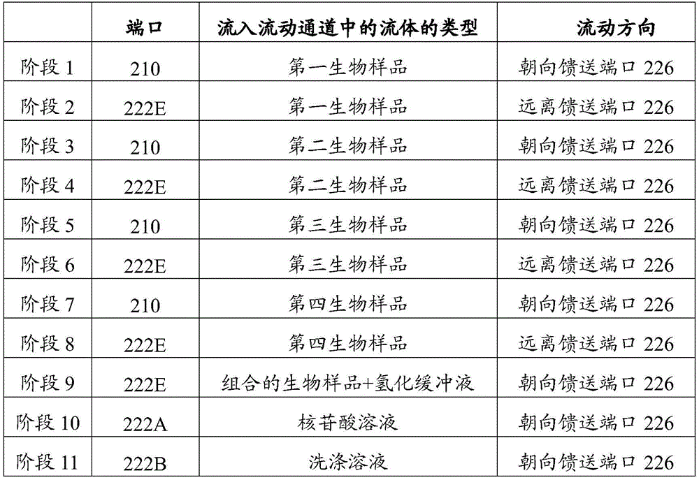

图11示出检测组件400的一部分的横截面。在示出的实施方案中,检测组件400与流动单元320一体地形成。更具体地,检测组件包括检测设备404,检测设备404邻近流动单元320和反应室326定位。流动单元320可以安装至检测设备404。在示出的实施方案中,流动单元320通过一个或多个固定机构(例如,粘合剂、粘结剂、紧固件等)直接固定到检测设备404。在一些实施方案中,流动单元320可以可移除地联接至检测设备404。在特定的实施方案中,检测设备404构造成检测来自反应室326的光信号。因此,在一些实施方案中,检测设备404可以称为成像检测器。FIG. 11 shows a cross-section of a portion of
在示出的实施方案中,检测设备404包括设备基座425。在特定的实施方案中,检测设备404包括多个堆叠层(例如,硅层、电介质层、金属-电介质层等)。设备基座425可以包括光传感器440的传感器阵列424、光导462的引导阵列426和具有对应反应位点414的反应凹部408的反应阵列428。在某些实施方案中,部件布置成使得每个光传感器440与单个光导462和单个反应位点414对齐。然而,在一些实施方案中,单个光传感器440可以通过一个以上的光导462和/或从一个以上的反应位点414接收光子。如本文所使用的,单个光传感器可以包括一个像素或一个以上的像素。检测设备404可以使用互补金属氧化物半导体(CMOS)技术制造。在特定的实施方案中,检测设备404是CMOS成像检测器。In the illustrated embodiment,
应注意,术语“阵列”或“子阵列”不一定必然包括检测设备可以具有的某一类型的每个项。例如,传感器阵列424可以不包括检测设备404中的每个光传感器。反而,检测设备404可以包括其它光传感器(例如,光传感器的其它阵列)。作为另一个示例,引导阵列426可以不包括检测设备的每个光导。反而,可以存在与光导462被不同地构造或者与检测设备404的其它元件具有不同关系的其它光导。因此,除非另有明确地陈述,否则术语“阵列”可以包括或可以不包括检测设备的所有这样的项。It should be noted that the term "array" or "sub-array" does not necessarily necessarily include every item of a certain type that a detection device may have. For example,
在示出的实施方案中,流动单元320包括侧壁406和由侧壁406和其它侧壁(未示出)支撑的流动盖410。侧壁联接到检测器表面412并且在流动盖410和检测器表面412之间延伸。在一些实施方案中,侧壁由将流动盖410结合到检测设备404的可固化粘合剂层形成。In the illustrated embodiment, the
流动单元320被设定尺寸并成形为使得反应室326存在于流动盖410和检测设备404之间。如所示,反应室326可以包括高度H1。仅举例来说,高度H1可以在大约50-400μm(微米)之间,或更具体地,在大约80-200μm之间。在示出的实施方案中,高度H1为大约100μm。流动盖410可以包括对从检测组件400的外部传播到反应室326中的激发光401可透射的材料。如在图7中示出的,激发光401以非正交的角度接近流动盖410。然而,这仅仅是为了说明的目的,因为激发光401可以从不同的角度接近流动盖410。反应室326被设定尺寸并成形为沿检测器表面412引导流体。反应室326的高度H1和其它尺寸可以构造成维持流体的沿着检测器表面412的大体上均匀的流动。反应室326的尺寸还可以构造成控制气泡形成。
侧壁406和流动盖410可以是彼此联接的分离的部件。在其它的实施方案中,侧壁406和流动盖410可以一体地形成,使得侧壁406和流动盖410由连续的材料片形成。举例来说,流动盖410(或流动单元320)可以包括例如玻璃或塑料的可透射的材料。流动盖410可以构成具有平面的外表面和界定反应室326的平面的内表面的大体上矩形的块。该块可以安装到侧壁406上。可选地,流动单元320可以被蚀刻以界定流动盖410和侧壁406。例如,凹部可以被蚀刻到可透射材料中。当蚀刻材料安装到检测设备404时,凹部可以变成反应室326。
检测设备404具有检测器表面412,检测器表面412可以被功能化(例如,以合适方式进行化学或物理地改变,以用于进行指定反应)。例如,检测器表面412可以被功能化并且可以包括具有固定到其上的一个或多个生物分子的多个反应位点414。检测器表面412具有反应凹部或侧部开口式反应凹部408的阵列。反应凹部408中的每一个可以包括一个或多个反应位点414。反应凹部408可以由例如沿检测器表面412的凹口或深度的变化界定。在其它的实施方案中,检测器表面412可以是大体上平面的。The
如在图11中示出的,反应位点414可以沿检测器表面412以图案的方式分布。例如,反应位点414可以以类似于微阵列的方式沿检测器表面412位于行和列中。然而,应理解,可以使用反应位点的各种图案。反应位点可以包括发射光信号的生物物质或化学物质。例如,反应位点的生物物质或化学物质可以响应于激发光401产生光发射。在特定的实施方案中,反应位点414包括固定在检测器表面412上的生物分子(例如,核酸)的簇或集群。As shown in FIG. 11 ,
图12是方法470的流程图。在一些实施方案中,方法470可以包括制备生物样品和/或检测用于分析的生物样品的指定反应。方法470可以例如使用本文所讨论的各种实施方案(例如,系统和/或方法)的结构或方面。在各种实施方案中,某些步骤可以被省略或添加,某些步骤可以被组合,某些步骤可以被同时执行,某些步骤可以被并发地执行,某些步骤可以分成多个步骤,某些步骤可以以不同的顺序执行,或某些步骤或一系列步骤可以以迭代方式重新执行。FIG. 12 is a flowchart of
方法470可以使用与流动控制系统200(图2)类似或相同的流动控制系统来进行或执行。方法470包括(在472处)将旋转阀旋转至第一阀位置。该旋转阀具有至少一个流动通道。在第一阀位置中,流动通道可以与样品通道(或流动控制系统的其它储器)流动连通并且与反应室流动连通,使得流动通道流体地联接样品通道和反应室。例如,旋转阀可以具有第一通道端口和第二通道端口。第一通道端口可以与端口(例如,供应端口或储器端口)对齐,并且第二通道端口可以与馈送端口对齐。当旋转阀处于第一阀位置时,其它端口可以被旋转阀密封,使得流体被阻挡穿过其它端口流动。
方法470还可以包括当旋转阀处于第一阀位置时使生物样品从样品通道(或第一储器)流入流动通道中(在474处)。例如,生物样品可以流过供应端口进入至旋转阀的流动通道中。作为另一个示例,生物样品可以布置在储器内,例如,容纳氢化缓冲液的储器。生物样品(具有氢化缓冲液)可以流过储器端口并进入至流动通道中。
任选地,生物样品可以继续流入反应室中(在476处)。可选地,方法470可以包括将旋转阀旋转至第二阀位置,同时生物样品布置在在流动通道内(在478处)。在第二阀位置中,流动通道可以流体地联接至另一个储器,例如,容纳氢化缓冲液的储器。在480处,可以诱导流动通道内的生物样品流动(例如,通过泵组件)到储器中。方法470然后可以包括重复步骤472、474、478以及480,直到所需要的生物样品中的每一个布置在在公共储器内。在482处,具有氢化缓冲液的生物样品可以同时流过流动通道并进入反应室中。Optionally, the biological sample can continue to flow into the reaction chamber (at 476). Optionally,
因此,一个或多个生物样品可以利用旋转阀被引导至反应室中。在可选的实施方案中,生物样品(或多个样品)具有至反应室的直接通道,并且不流过旋转阀。任选地,方法470可以通过指定的操作,例如关于表1所描述的操作开始循环以进行指定的反应。例如,旋转阀可以旋转(在484处)至另一个阀位置,以将反应室流体地联接至指定的储器。在486处,反应成分可以流动到反应室中以与其中的生物样品相互作用。任选地,在488处,方法470包括检测反应室内的指定反应。方法470然后可以返回至步骤484。Thus, one or more biological samples can be directed into the reaction chamber using the rotary valve. In alternative embodiments, the biological sample (or samples) has direct access to the reaction chamber and does not flow through the rotary valve. Optionally,
图13是根据实施方案形成的旋转阀500的平面图,旋转阀500旋转地安装至微流体主体504的主体侧502。旋转阀500可以包括类似于旋转阀216(图2)的特征。微流体主体504包括构造成保持反应成分和/或生物样品的多个储器506-510。更具体地,储器506-509保持第一、第二、第三以及第四生物样品(或样品液体)。储器510包括氢化缓冲液。储器506-510中的每一个通过在图13中由线表示的相应的储器通道516-520流体地联接到对应的端口。如示出的,端口包括开向主体侧502并与储器506-510流动连通的储器或供应端口526-530。微流体主体504还包括开向主体侧502的馈送端口524(图13中示出)。13 is a plan view of a
旋转阀500包括具有流体侧513(图14中示出)的阀主体512,流体侧513接合主体侧502和相对的操作侧514。阀体512包括第一、第二、第三和第四流动通道536-539。流动通道536-539中的每一个构造成在扩增或PCR方案期间保持生物样品。流动通道536-539中的每一个具有居中地定位的公共通道端口(或出口端口)544。在其它的实施方案中,流动通道536-539不共用同一个通道端口。公共通道端口544位于旋转阀500围绕其旋转的轴线542处。流动通道536-539包括相应的第一通道端口(或入口端口)546-549。因此,流动通道536-539中的每一个从对应的第一通道端口546-549延伸到公共通道端口544。类似于旋转阀216(图2),旋转阀500构造成旋转至不同的阀位置以流体地联接储器和通道。然而,与旋转阀500不同,旋转阀500可以在扩增方案期间使用。更具体地,阀主体512可以接合热循环器570(图14中示出),同时生物样品保持在流动通道536-539内。The
在一些实施方案中,流动通道536-539可以具有防扩散段545。防扩散段545构造成当流动通道536-539内的生物样品经受PCR方案时降低扩散发生的可能性。例如,图13中示出的流动通道536-539具有沿着路径变化的非线性路径和尺寸。更具体地,流动通道536-539具有随着流动通道从对应的第一通道端口朝向公共通道端口544延伸而来回环绕的蛇形或波状路径。第一通道端口546-549具有径向朝外的位置。除了流动通道536-539的形状,流动通道536-539具有随着流动通道536-539从对应的第一通道端口延伸到公共通道端口544而减小的尺寸。在其它的实施方案中,防扩散段545不具有蛇形路径。不包括防扩散段545的流动通道536-539的段可以被称为样品制备区域543,样品制备区域543表示对应的流动通道的一部分,在该样品制备区域543中生物样品可以经历不同的情况,例如,温度变化。然而,应理解,对于至少一些实施方案,生物样品还可以存在于防扩散段545内。In some embodiments, the flow channels 536-539 can have a diffusion-
图14示出当热循环器570安装到操作侧514时旋转阀500的侧截面。在一些实施方案中,热循环器570可以提供抵靠微流体主体504的主体侧502按压阀主体512的安装力572。尽管在图14中未示出,阀主体512可以包括被热循环器570接合的一个或多个机械界面(例如,非平面特征,例如翅片)。热循环器570构造成控制流动通道536-539的温度。在特定的实施方案中,热循环器570同时控制流动通道536-539中的每一个的温度。在其它的实施方案中,热循环器570可以单次选择性地接合少于所有的流动通道。FIG. 14 shows a side section of the
如在图14中示出的,公共通道端口544流体地联接至馈送端口524。轴线542延伸穿过公共通道端口544和馈送端口524。流动通道537的第一通道端口547流体地联接至储器端口527。然而,流动通道539的第一通道端口549由主体侧502密封。因此,在图14中所示的阀位置中,流体(例如,含有生物样品的流体)可从储器507(图13)流动并进入流动通道537中。As shown in FIG. 14 ,
图15A-图15L是旋转阀500的平面图并示出可以发生不同操作的不同的阀位置。为了准备好扩增方案,例如系统控制器180(图1)的系统控制器构造成选择性地控制泵组件(未示出)和旋转阀500。该泵组件可以类似于泵组件332并包括一个或多个流动泵。在一些实施方案中,单个泵可以相对于旋转阀500位于下游,并且构造成通过公共通道端口544(图15A)汲取流体。15A-15L are plan views of
任选地,流动通道536-539(图15A)可以在接收生物样品之前用流体装填。例如,图15A-图15D示出了对应流动通道的第一通道端口,其流体地联接到与储器510流动连通的储器端口530。因此,每一个流动通道的第一通道端口可以单独地联接到储器510。当流动通道与储器510流动连通时,系统控制器可以选择性地致动泵组件,以诱导储器510内的反应成分流动,使得反应成分流入对应的流动通道中。Optionally, flow channels 536-539 (FIG. 15A) can be filled with fluid prior to receiving a biological sample. For example, FIGS. 15A-15D illustrate a first channel port of a corresponding flow channel fluidly coupled to a
因此,在图15D之后,流动通道536-539中的每一个装填有反应成分。尽管反应成分与储器510相关联,但是其它反应成分可以装填流动通道536-539。例如,流动通道536-539可以流体地联接至包含例如,水或缓冲溶液的单独的储器(未示出)。在示出的实施方案中,流动通道536-539中的每一个可分离地联接至储器510。在可选的实施方案中,流动通道536-539中的一个或多个可以同时联接至储器510或单独的储器。Thus, following Figure 15D, each of flow channels 536-539 is filled with reaction components. While a reaction component is associated with
在流动通道536-539已经被装填后,来自储器506-509(图15E)的生物样品可以分别装载到流动通道536-539(图15E)中。例如,如图15E中所示,流动通道538流体地联接至储器端口528且如此,与储器508流动连通。此时,流动通道536、537以及539被主体侧502覆盖。泵组件可以诱导储器508内的生物样品的流动,使得生物样品流入流动通道538中。流动量可以基于储器508内的流体的量。在生物样品已经被装载到流动通道538中之后,旋转阀500可以选择性地旋转,并且泵组件可以以类似的方式被选择性地致动以将储器506、507和509的生物样品分别装载到流动通道536、537和539中,如图15F-图15H中所示。After flow channels 536-539 have been filled, biological samples from reservoirs 506-509 (FIG. 15E) can be loaded into flow channels 536-539 (FIG. 15E), respectively. For example, as shown in FIG. 15E ,
在生物样品装载在对应的流动通道536-539内的情况下,旋转阀500可以选择性地旋转,使得第一通道端口546-549中的每一个由微流体主体504的主体侧502覆盖(或密封)。第一通道端口546-549密封在其中的阀位置在图15I中示出。然后可以控制热循环器570(图14)以根据指定的扩增方案循环通过温度变化。尽管流动通道536-539仅仅在一端部处密封,但是泵组件和防扩散段545可以阻止生物样品(例如,PCR塞)移动和/或扩散到馈送端口524中或移动或扩散穿过馈送端口524(图14)。With a biological sample loaded within a corresponding flow channel 536-539, the
在扩增方案之后,生物样品可以被装载至公共储器中。例如,如图15J-15L中所示,流动通道536-538内的生物样品可以流体地联接至储器510。泵组件可以被选择性地操作以诱导生物样品流入储器510中。尽管未示出,但是流动通道536还可以流体地联接至储器510,使得流动通道536内的生物样品可以被装载至储器510中。因此,来自储器506-509中的每一个生物样品可以在扩增方案之后被装载到公共储器510中。泵组件然后可以被选择性地致动以诱导混合的生物样品流过馈送端口524。生物样品可以被流体地输送至反应室,例如反应室326(图2)。生物样品然后可经历如本文所述的指定反应。在特定的实施方案中,生物样品可以在SBS方案期间使用。Following the amplification protocol, biological samples can be loaded into the common reservoir. For example, as shown in FIGS. 15J-15L , biological samples within flow channels 536 - 538 may be fluidly coupled to
图16是根据实施方案形成的旋转阀600的平面图,该旋转法600安装至微流体主体618的主体侧616。旋转阀600可以包括类似于旋转阀216(图2)和旋转阀500(图13)的特征。旋转阀600包括具有流动通道604-606的阀主体602。流动通道604-606中的每一个在第一通道端口(或入口端口)和第二通道端口(或出口端口)610之间延伸。不像旋转阀500,流动通道604-606不与公共通道端口流动连通。16 is a plan view of a
在示出的实施方案中,流动通道604-606中的每一个与上游通道612和下游通道614流动连通。在图16中,旋转阀600处于阀位置中,使得流动通道604-606中的每一个可以接收来自对应的上游通道612的生物样品。例如,流动通道604-606可以同时接收对应的生物样品。进入到流动通道604-606中的生物样品的流动可以通过公共泵来诱导。例如,下游通道614可以合并在一起并且流体地联接到单个泵。可选地,单独的泵可以流体地联接到流动通道604-606。In the illustrated embodiment, each of the flow channels 604 - 606 is in flow communication with an
图17是旋转阀已经旋转至阀位置之后旋转阀600的平面图,其中用于流动通道604-606中的每一个的第一和第二通道端口608、610由微流体主体618的主体侧616密封。在图17中示出的阀位置中,热循环器(未示出)可以接合阀主体602以控制流动通道604-606内所经历的温度。因此,生物样品可以经历如本文所描述的扩增方方案。不像在图13-15中示出的实施方案,流动通道604-606在两个端部处被密封以降低PCR塞的扩散和移动的可能性。17 is a plan view of the
图18是根据实施方案形成的旋转阀602的平面图。旋转阀620可以与旋转阀600(图16)类似或相同,并且包括多个流动通道624-626。如示出的,旋转阀600被分成三个热控制区域或区634-636。热控制区域634-636由用虚线表示的饼形区域表示。每一个热控制区域634-636表示由一个或多个热循环器(未示出)控制的不同温度范围。更具体地,在将生物样品装载到流动通道624-626中之后,旋转阀620可以选择性地旋转到不同位置。热控制区域634内的流动通道可以经历变性核酸的指定温度。热控制区域635内的流动通道可以经历用于退火-延伸阶段的指定温度,并且热控制区域636内的流动通道可以经历用于预加热和/或温度保持阶段的指定温度。系统控制器可以选择性地将旋转阀620旋转到三个不同的阀位置,以使生物样品循环通过多个PCR扩增阶段。因此,与旋转阀600的流动通道不同,流动通道624-626经历不同的温度。Figure 18 is a plan view of a rotary valve 602 formed in accordance with an embodiment.
图19是示出方法650的流程图。在一些实施方案中,方法650可以包括制备生物样品,和任选地检测用于分析的生物样品的指定反应。方法650可以例如使用本文所描述的各种实施方案(例如,系统和/或方法)的结构或方面,例如,关于图13-图18描述的实施方案。在各种实施方案中,某些步骤可以被省略或添加,某些步骤可以被组合,某些步骤可以被同时执行,某些步骤可以被并发地执行,某些步骤可以被分成多个步骤,某些步骤可以以不同的顺序执行,或某些步骤或一系列步骤可以以迭代方式重新执行。FIG. 19 is a
方法650可以包括(在652处)提供微流体主体和旋转阀。微流体主体可以具有主体侧和流体网络,流体网络包括供应端口(例如,储器端口526-529)和馈送端口。供应端口开向主体侧。该旋转阀可以旋转地安装至主体侧,且该旋转阀具有第一通道端口、第二通道端口以及在第一通道端口和第二通道端口之间延伸的流动通道。在一些实施方案中,可以使用多个流动通道,其中流动通道具有分离的第二通道端口,例如图16-图18的实施方案,或者共用第二通道端口,例如图13-图15的实施方案。在其中第二通道端口被共用的这样的实施方案中,第二通道端口可以被称为公共通道端口。
方法650可以包括(在654处)将旋转阀旋转至第一阀位置,第一通道端口在该第一阀位置与微流体主体的供应端口流动连通。方法650还可以包括(在656处)当该旋转阀处于第一阀位置时,使生物样品流过该第一通道端口并流入该流动通道中。生物样品可以在从第一通道端口且朝向第二通道端口的方向上流动。该流动(在656处)可以包括选择性地控制流动的流速和/或持续时间,使得生物样品基本上不流过第二通道端口或馈送端口。对于包括多个流动通道,例如旋转阀500的实施方案,可以重复步骤654和656直到流动通道中的每一个具有相应的生物样品。然而,每个流动通道的旋转(在654处)不是到相同的阀位置。更具体地,当生物样品流入对应的流动通道中时,其它流动通道可以在一端部或两端部处密封。
方法650还可以包括(在658处)在生物样品在流动通道内的情况下将旋转阀旋转至第二阀位置,使得第一通道端口被主体侧密封以及执行(在660处)热循环操作以将流动通道中的生物样品的温度改变到选定的温度。该执行(在660处)可以根据预定的方案。例如,该一览表可以将要执行PCR操作以便扩用于随后的分析增生物样品。
任选地,在该执行(在660处)之后,生物样品或多个生物样品可以被装载(在662处)至储器中。例如,储器可以包括制备用于随后分析的生物样品的氢化缓冲溶液。在664处,生物样品(或组合的生物样品)可以被输送至反应室,以用于在666处的随后的分析。Optionally, following this performing (at 660), the biological sample or samples may be loaded (at 662) into the reservoir. For example, a reservoir may contain a hydrogenated buffer solution for preparing a biological sample for subsequent analysis. At 664 , the biological sample (or combined biological sample) can be delivered to the reaction chamber for subsequent analysis at 666 .
图20是根据实施方案形成的流动控制系统700的透视图,该系统包括微流体主体702和旋转阀704。不像旋转阀500(图13)、旋转阀600(图16)以及旋转阀620(图18),扩增不仅仅在旋转阀704内发生。相反,扩增至少部分地发生在微流体主体702内。更具体地,微流体主体702具有面向相反方向的第一主体侧706(图22中示出)和第二主体侧708(图22中示出)。微流体主体702具有流体网络705,其包括多个样品储器711-714、具有对应的入口端口731-734的多个供应通道721-724,以及公共出口端口736。入口端口731-734和出口端口736开向第一主体侧706(图22)。20 is a perspective view of a
旋转阀704沿第一主体侧706旋转地安装至微流体主体702。在示出的实施方案中,旋转阀704具有第一通道段726和第二通道段728。第一和第二通道段726、728开向阀主体704的流体侧709(图22所示)。可选地,第一和第二通道段726、728可以在开向流体侧709的对应的通道端口之间延伸。第一和第二通道段726、728彼此分离并且沿流体侧709的仅一部分延伸。在示出的实施方案中,第二通道段728在旋转阀704的任何旋转位置处与出口端口736流动连通。A
图20示出处于指定位置中的旋转阀704,其中样品储器711与泵组件流动连通。更具体地,第一通道段726流体地介于入口端口731和样品储器711之间。第二通道段726流体地介于样品储器711和出口端口736之间。因此,供应通道721通过第一通道段726、样品储器711以及第二通道段728与馈送通道756流动连通。Figure 20 shows the
尽管未示出,流动控制系统700可以包括泵组件,泵组件构造成诱导流体流过入口端口731和第一通道段726进入样品储器711中。流体可以包括装载在例如与供应通道721流动连通的远离的储器(未示出)中的生物样品。流体的流动和样品储器的尺寸可以构造成使得生物样品大体上不穿过第二通道段728离开样品储器711。在将生物样品装载到样品储器711中之后,旋转阀704可以选择性地旋转,使得第一通道段726和第二通道段728流体地联接到样品储器712。样品储器712可以装载有从供应通道722流动的生物样品。样品储器713和714可以以类似的方式装载有对应的生物样品。Although not shown,
图21是样品储器711-714已经装载有对应的生物样品之后流动控制系统700的透视图。在一些实施方案中,旋转阀704包括气体储器741-744,其在图20中示出。在扩增方案期间,气体储器741-744构造成与样品储器711-714对齐。例如,如图22中所示,样品储器711和气体储器741结合以形成样品制备室751。气体储器741内的气体可以用作样品制备室751中的气镇(gas ballast)。在热循环之后,生物样品可以流过与出口端口736流动连通的馈送通道756(图20)。如本文所述,生物样品可以被引导至反应室,例如反应室326(图2),其中指定的反应可以发生并被检测。21 is a perspective view of
图23是根据实施方案形成的系统800的示意图。系统800可以包括类似于系统100(图1)的特征。例如,系统800包括具有流体网络804的流动控制系统802。流体网络804可以包括构造成保持穿过其的流体流动或具有流体流过其中的多个互连的通道、端口、储器以及其它空间区域。例如,流体网络804包括旋转阀806、808。旋转阀806构造成在样品制备阶段期间被使用,并且旋转阀808构造成在样品分析阶段期间被使用。旋转阀806、808通过流体网络804的中间通道810被流体地联接。流体网络804还包括馈送通道812、反应室814以及废物储器816。流动控制系统802包括与流体网络804流动连通的泵组件818。在示出的实施方案中,泵组件818包括单个泵,但是在其它的实施方案中可以包括多个泵。系统800可以包括具有主体侧819的微流体主体(未指示)。旋转阀806、808旋转地安装至主体侧819。微流体主体还可以包括或界定中间通道810和馈送通道812。Figure 23 is a schematic diagram of a
流体网络804还包括多个测定通道821-824和多个样品储器831-834。每个测定通道821-824在对应的第一和第二端口826、828之间延伸,并且构造成将对应的样品储器流体地联接到中间通道810。如所示,测定通道821-824延伸穿过热控制区域825。在示出的实施方案中,测定通道821-824具有穿过热控制区域825的波状路径825。延伸穿过热控制区域825的测定通道821-824的部分可以构成样品制备区域827。可选地或除了非线性路径之外,测定通道821-824可以具有不同的尺寸以容纳指定体积的对应的生物样品。
旋转阀806构造成在多个阀位置之间移动。旋转阀806包括桥式通道840和流动通道842。桥式通道840和流动通道842构造成将样品储器831-834中的一个流体地联接至中间通道810。例如,如图23中所示,桥式通道840将样品储器833的储器端口(或供应端口)流体地联接至测定通道823的第一端口826。同时,流动通道842将第二端口828流体地联接到中间端口856。中间端口856沿着主体侧819打开并且与中间通道810流动连通。
因此,系统控制器(未示出)可以选择性地使旋转阀806旋转,以将样品储器831-834分别流体地联接到对应的测定通道821-824。系统控制器可以选择性地控制泵组件818以诱导样品储器内的生物样品的流动,使得生物样品布置在测定通道821-824的样品制备区域827内。Accordingly, a system controller (not shown) may selectively rotate
当生物样品(或多个样品)位于对应的测定通道内时,旋转阀806可以由系统控制器旋转到其中用于每一个测定通道821-824的第一和第二端口826、828被主体侧819覆盖或密封的另一个阀位置。在测定通道被密封的情况下,生物样品可以经历扩增方案。例如,热循环器(未示出)可以邻近热控制区域825定位,并根据扩增方案施加热能。在特定的实施方案中,生物样品中的每一个可以同时定位在热控制区域825内。在可选的实施方案中,生物样品可以在分开的时间定位在热控制区域825内。The
在生物样品已经被扩增之后,旋转阀806可以返回到对应的阀位置,以将对应的生物样品装载到流动通道842中。在生物样品布置在流动通道842内的情况下,旋转阀可以旋转到其中流动通道842与储器835流动连通的另一位置。储器835可以包含例如氢化缓冲溶液。生物样品可以被装载到储器835中。任选地,旋转阀806和泵组件818可以以类似的方式操作,以将来自其它测定通道的生物样品装载到储器835中。生物样品然后可以朝向另一个阶段被引导。例如,生物样品可以流过流动通道842,穿过中间端口856,并进入中间通道810。在可选的实施方案中,生物样品可以朝向旋转阀808被引导,而不首先被装载到储器835中。After the biological sample has been amplified, the
如图23中所示,旋转阀808包括流动通道870和多个试剂储器871-878。在使用旋转阀806已经制备生物样品之后,生物样品可以被运送到反应室814中。任选地,在将生物样品输送到反应室814之前,旋转阀808可以旋转以将试剂储器871-878中的一个或多个流体地联接到反应室814。更具体地,流动通道870可以旋转到指定位置以将试剂储器871-878中的一个流体地联接到反应室814。因此,旋转阀808可以用于使反应室814准备好接收生物样品。例如,试剂储器871-878可以包括聚类试剂、酶和/或捕获探针。As shown in Figure 23, the
在将生物样品输送到反应室814之后,旋转阀808可选择性地旋转到不同的阀位置。例如,旋转阀808可以根据预定循环旋转以重复地输送用于进行SBS方案的反应成分。该循环可以类似于上面表1中所示出的循环。因此,旋转阀808可以用于使反应室准备好接收生物样品和/或用于进行测定方案。After delivering the biological sample to the
图24和图25示出利用具有桥式通道的旋转阀的另一个实施方案。图24是流动控制系统900的平面图,以及图25是流动控制系统900的局部分解透视图。如所示,流动控制系统900包括具有相对的第一和第二主体侧904、906(图25)的微流体主体902。微流体主体902包括多个流动通道908和多个样品储器910。流动通道908中的每一个构造成流体地联接至相应的样品储器910。流动通道908在形状和尺寸上可以与流动通道536-539(图13)类似。Figures 24 and 25 show another embodiment utilizing a rotary valve with bridged passages. FIG. 24 is a plan view of
流动控制系统900还包括旋转阀912。旋转阀912包括多个桥式通道913-916,该多个桥式通道913-916构造成流体地联接对应的流动通道908和样品储器910。在特定的实施方案中,桥式通道913-916中的每一个是沿着旋转阀912的外部的侧部开口式凹槽。在可选的实施方案中,桥式通道913-916不是侧部开口式的,而是在通向外部的第一端口和第二端口之间延伸。举例来说,图24中的桥式通道916基于旋转阀912的旋转位置将对应的样品储器910流体地联接到对应的流动通道908。当生物样品流过桥式通道913时,其它的桥式通道914-916不被流体地联接到对应的样品储器910。更具体地,其它的桥式通道914-916被旋转阀912密封。The
热循环器(未示出)可以以与在其它实施方案中描述的类似的方式改变由流动通道908内的生物样品所经历的温度。例如,主体侧904、906中的一个或两个可以被热循环器接合。在扩增方案之后,可以将生物样品输送到另一空间区域,以用于另外的改变/制备和/或分析。A thermal cycler (not shown) can vary the temperature experienced by the biological sample within
如上所描述,在各种实施方案中,旋转阀和微流体主体可以包括不同的流体元件,该不同的流体元件协作以以指定的方式控制一个或多个流体的流动。应理解,上面的实施方案仅仅是说明性的而不是限制性的。例如,上述实施方案(和/或其方面)可以彼此组合使用。此外,可以进行许多修改以使特定情况或材料适应各种实施方案的教导,而不不脱离其范围。As described above, in various embodiments, the rotary valve and microfluidic body can include distinct fluidic elements that cooperate to control the flow of one or more fluids in a specified manner. It should be understood that the above embodiments are illustrative only and not restrictive. For example, the above-described embodiments (and/or aspects thereof) may be used in combination with each other. In addition, many modifications may be made to adapt a particular situation or material to the teachings of various embodiments without departing from the scope thereof.
图26-图29示出根据实施方案形成的旋转阀950的各种视图。旋转阀950可以在各种实施方案中用作旋转阀,例如,旋转阀216(图2)。图26和图27分别示出旋转阀950的底部透视图和侧透视图。旋转阀950包括流体侧952和操作侧954。操作侧954包括构造成接合阀致动器(未示出)的机械接口956。26-29 show various views of a
图28示出旋转阀950的横截面;如所示,旋转阀950包括相对于彼此固定在固定位置中的外壳盖960和侧盖964。外壳盖960界定阀腔962,并且侧盖964沿着流体侧952封闭阀腔962的一端。旋转阀950还包括转子轴966,转子轴966包括均布置在阀腔962内的机械接口956、阀弹簧968、歧管主体970以及可压缩膜972。转子轴966构造成使歧管主体970和可压缩膜972沿侧盖964围绕轴线978旋转。Figure 28 shows a cross-section of
歧管主体970在一侧上固定至转子轴966且在相对侧上固定至可压缩膜972。阀弹簧968可以抵靠侧盖964的内表面偏置或推动歧管主体970和可压缩膜972。在特定的实施方案中,可压缩膜972可以是聚丙烯或其它类似材料。暂时回到图26,侧盖964包括中心流动端口980、排放端口981以及外部流动端口982。侧盖964在图26中是部分透明的,以表示出中心流动端口980、排放端口981以及外部流动端口982。示出了总共九个外部流动端口982,但是其它实施方案可以包括不同数量的端口。The
图29是表示歧管主体970、可压缩膜972以及侧盖964之间的相互作用的旋转阀950的放大的横截面。如所示,侧盖964和可压缩膜972可以界定它们之间的润滑剂储器990。润滑剂储器990可以围绕轴线978延伸。在一些实施方案中,还可以提供外部润滑剂储器991。在图26中也表示了润滑剂储器990。排放端口981与润滑剂储器990流动连通,使得润滑剂可以被装载到储器990中。如所示,歧管主体970和可压缩膜972界定它们之间的流动通道984。当转子轴966使可压缩膜972和歧管主体970一起旋转时,流动通道984随其旋转。由于可压缩膜972和润滑剂储器980,可以减小抵抗旋转的摩擦力。因此,旋转阀950的操作寿命可以比其它已知的阀更长。FIG. 29 is an enlarged cross-section of the
根据实施方案,提供了一种系统,其包括具有样品通道、反应室和储器的流体网络。该样品通道与构造成接纳生物样品的生物端口流动连通。该系统还包括泵组件,泵组件构造成与该流体网络流动连通。该系统还包括旋转阀,旋转阀具有流动通道并构造成在第一阀位置和第二阀位置之间旋转。当该旋转阀处于第一阀位置时,该流动通道流体地联接该反应室和样品通道,并且当该旋转阀处于第二阀位置时,该流动通道流体地联接储器和反应室。当该旋转阀处于第一阀位置时,该泵组件诱导生物样品朝向反应室流动,并且当该旋转阀处于第二阀位置时,该泵组件诱导反应成分从储器流向反应室。According to an embodiment, a system is provided that includes a fluid network having a sample channel, a reaction chamber, and a reservoir. The sample channel is in flow communication with a biological port configured to receive a biological sample. The system also includes a pump assembly configured to be in flow communication with the fluid network. The system also includes a rotary valve having a flow passage and configured to rotate between a first valve position and a second valve position. The flow channel fluidly couples the reaction chamber and the sample channel when the rotary valve is in the first valve position, and the flow channel fluidly couples the reservoir and the reaction chamber when the rotary valve is in the second valve position. The pump assembly induces flow of biological sample toward the reaction chamber when the rotary valve is in a first valve position, and induces flow of reaction components from the reservoir to the reaction chamber when the rotary valve is in a second valve position.
一方面,泵组件可以包括与反应室流动连通并且相对于反应室位于下游的系统泵。In one aspect, the pump assembly can include a system pump in flow communication with and downstream relative to the reaction chamber.
另一方面,旋转阀可以被构造成当旋转阀从第一阀位置旋转到第二阀位置时,将生物样品保持在流动通道中。泵组件可以构造成当旋转阀处于第二阀位置中时,诱导生物样品流动进入储器中。In another aspect, the rotary valve can be configured to retain the biological sample in the flow channel when the rotary valve is rotated from the first valve position to the second valve position. The pump assembly can be configured to induce flow of the biological sample into the reservoir when the rotary valve is in the second valve position.
任选地,样品通道可以是第一样品通道,并且生物样品可以是第一生物样品。流体网络可以包括具有第二生物样品的第二样品通道。旋转阀可以构造成旋转到第三阀位置,使得流动通道与第二样品通道流动连通。泵组件可以构造成诱导第二样品通道中的第二生物样品流入流动通道中,其中旋转阀构造成当旋转阀从第三阀位置旋转到第二阀位置时,将第二生物样品保持在流动通道中。泵件可以构造成当旋转阀处于第二阀位置中时,诱导其中的第二生物样品流动进入储器中。在一些实施方案中,泵组件可以构造成诱导第一和第二生物样品从储器朝向反应室流动。Optionally, the sample channel can be a first sample channel and the biological sample can be a first biological sample. The fluid network can include a second sample channel with a second biological sample. The rotary valve may be configured to rotate to a third valve position such that the flow channel is in flow communication with the second sample channel. The pump assembly can be configured to induce a second biological sample in the second sample channel to flow into the flow channel, wherein the rotary valve is configured to maintain the second biological sample in the flow channel when the rotary valve is rotated from the third valve position to the second valve position. channel. The pump member may be configured to induce flow of the second biological sample therein into the reservoir when the rotary valve is in the second valve position. In some embodiments, the pump assembly can be configured to induce flow of the first and second biological samples from the reservoir toward the reaction chamber.
另一方面,储器可以是第一储器。流体网络还可以包括第二储器,其中旋转阀可以构造成移动至第三阀位置,使得流动通道流体地联接第二储器和反应室。In another aspect, the reservoir may be a first reservoir. The fluid network can also include a second reservoir, wherein the rotary valve can be configured to move to a third valve position such that the flow channel fluidly couples the second reservoir and the reaction chamber.
另一方面,样品通道可以是第一样品通道且流体网络包括第二样品通道。任选地,第一和第二样品通道中的每一个通过公共供应端口与旋转阀流动连通。任选地,该系统还可以包括联接至样品通道的通道阀。阀通道可以构造成在第一位置和第二位置之间移动以分别阻挡流动穿过样品通道以及允许流动穿过样品通道。In another aspect, the sample channel can be a first sample channel and the fluid network includes a second sample channel. Optionally, each of the first and second sample channels are in flow communication with the rotary valve through a common supply port. Optionally, the system can also include a channel valve coupled to the sample channel. The valve channel may be configured to move between a first position and a second position to block flow through the sample channel and to allow flow through the sample channel, respectively.
另一方面,旋转阀可以围绕轴线旋转。流体网络可以包括馈送端口,该馈送端口与轴线对齐并流体地联接流动通道和反应室。Rotary valves, on the other hand, are rotatable about an axis. The fluid network may include feed ports aligned with the axis and fluidly coupling the flow channels and reaction chambers.
另一方面,流体网络还可以包括试剂通道。样品通道和试剂通道可以与相对于流动通道位于上游的公共供应端口流动连通。供应端口可以将样品通道和试剂通道流体地联接至流动通道。On the other hand, the fluidic network may also include reagent channels. The sample and reagent channels may be in flow communication with a common supply port located upstream relative to the flow channel. A supply port can fluidly couple the sample channel and the reagent channel to the flow channel.
另一方面,系统可以包括构造成检测反应室内的指定反应的检测组件。任选地,检测组件包括可以定位成检测来自反应室的光信号的成像检测器。任选地,成像检测器可以具有相对于流体网络的固定位置。In another aspect, the system can include a detection assembly configured to detect a given reaction within the reaction chamber. Optionally, the detection assembly includes an imaging detector positionable to detect an optical signal from the reaction chamber. Optionally, the imaging detector may have a fixed position relative to the fluid network.
另一方面,该系统包括系统控制器,该系统控制器可以构造成自动控制旋转阀和泵组件以进行合成测序(SBS)方案的迭代循环。In another aspect, the system includes a system controller that can be configured to automatically control the rotary valve and pump assembly for iterative cycles of a sequencing-by-synthesis (SBS) protocol.
在实施方案中,提供了一种方法,其包括将具有流动通道的旋转阀旋转到第一阀位置。当处于第一阀位置时,该流动通道与反应室流动连通。该方法还可以包括当旋转阀处于第一阀位置时使生物样品从样品通道或第一储器流动穿过流动通道并进入反应室。该方法还包括将旋转阀旋转至第二阀位置。当处于第二阀位置时,该流动通道可以流体地连接第二储器和反应室。该方法还包括使反应成分从第二储器流入反应室中。该反应成分在反应室内与生物样品相互作用。In an embodiment, a method is provided that includes rotating a rotary valve having a flow passage to a first valve position. The flow channel is in flow communication with the reaction chamber when in the first valve position. The method may also include flowing the biological sample from the sample channel or the first reservoir through the flow channel and into the reaction chamber when the rotary valve is in the first valve position. The method also includes rotating the rotary valve to a second valve position. The flow channel may fluidly connect the second reservoir and the reaction chamber when in the second valve position. The method also includes flowing reaction components from the second reservoir into the reaction chamber. The reaction components interact with the biological sample within the reaction chamber.
一方面,该方法可以包括检测反应室内的反应成分和生物样品之间的指定反应。任选地,检测指定反应可以包括检测来自反应室的光信号。光信号可以指示指定反应。In one aspect, the method can include detecting a given reaction between a reaction component within the reaction chamber and the biological sample. Optionally, detecting a given reaction can include detecting an optical signal from the reaction chamber. A light signal can indicate a given response.
另一方面,该方法还包括将多个生物样品单独地流入储器中,从而组合其中的生物样品。当旋转阀处于第一阀位置时,生物样品可以同时流过流动通道并进入反应室。In another aspect, the method further includes individually flowing a plurality of biological samples into the reservoir, thereby combining the biological samples therein. When the rotary valve is in the first valve position, the biological sample can simultaneously flow through the flow channel and into the reaction chamber.
另一方面,该方法还包括将旋转阀旋转到第三阀位置并使洗涤溶液从第三储器流入反应室中。该方法还可以包括将旋转阀旋转到第二阀位置并使反应成分从第二储器流入反应室中。任选地,该方法包括执行合成测序(SBS)方案的迭代循环。In another aspect, the method further includes rotating the rotary valve to a third valve position and flowing wash solution from the third reservoir into the reaction chamber. The method may also include rotating the rotary valve to a second valve position and flowing the reaction components from the second reservoir into the reaction chamber. Optionally, the method includes performing iterative cycles of a sequencing-by-synthesis (SBS) protocol.
另一方面,该方法还包括在使生物样品流过流动通道并进入反应室中之前,扩增样品通道或储器内的生物样品。In another aspect, the method further includes amplifying the biological sample within the sample channel or reservoir prior to flowing the biological sample through the flow channel and into the reaction chamber.
在一个实施方案中,提供一种系统,其包括具有流体网络的流控制系统和与该流体网络流动连通的泵组件。该流体网络包括样品通道、多个储器以及反应室,样品通道构造成接纳生物样品。该系统还包括具有流动通道的旋转阀。该旋转阀构造成旋转至不同的阀位置以将反应室流体地联接至样品通道或联接至储器中的一个。该系统还包括检测设备,其构造成在测定方案期间检测来自反应室的光信号。该系统还包括系统控制器,其构造成控制该旋转阀和泵组件以使生物样品从样品通道流动并使其流入反应室中。该系统控制器还构造成在多个方案循环期间控制旋转阀、泵组件以及检测设备,其中该方案循环中的每一个包括:(a)将旋转阀旋转至第一储器阀位置,使得反应室与多个储器中的第一储器流动连通;(b)控制泵组件以诱导流体从所述第一储器流入反应室;(c)将旋转阀旋转至第二储器阀位置,使得反应室与多个储器中的第二储器流动连通;(d)控制泵组件以诱导流体从第二储器流入反应室;以及(e)控制检测设备以在来自第二储器的流体流过反应室时或在来自第二储存器的流体流过反应室之后检测来自反应室的光信号。In one embodiment, a system is provided that includes a flow control system having a fluid network and a pump assembly in flow communication with the fluid network. The fluid network includes a sample channel configured to receive a biological sample, a plurality of reservoirs, and a reaction chamber. The system also includes a rotary valve having a flow channel. The rotary valve is configured to rotate to different valve positions to fluidly couple the reaction chamber to one of the sample channel or to the reservoir. The system also includes a detection device configured to detect the light signal from the reaction chamber during the assay protocol. The system also includes a system controller configured to control the rotary valve and pump assembly to flow the biological sample from the sample channel and into the reaction chamber. The system controller is also configured to control the rotary valve, pump assembly, and detection device during a plurality of protocol cycles, wherein each of the protocol cycles includes: (a) rotating the rotary valve to a first reservoir valve position such that the reaction the chamber is in flow communication with a first reservoir of the plurality of reservoirs; (b) controlling a pump assembly to induce flow of fluid from said first reservoir into the reaction chamber; (c) rotating the rotary valve to a second reservoir valve position, placing the reaction chamber in flow communication with a second reservoir of the plurality of reservoirs; (d) controlling a pump assembly to induce flow of fluid from the second reservoir into the reaction chamber; and (e) controlling the detection device to respond to fluid flow from the second reservoir An optical signal from the reaction chamber is detected as fluid flows through the reaction chamber or after fluid from the second reservoir flows through the reaction chamber.
一方面,样品通道可以包括样品制备区域。系统还可以包括构造成控制样品制备区域内的生物样品的温度的热循环器。系统控制器可以在生物样品从样品通道流入反应室中之前控制热循环器以扩增样品制备区域内的生物样品。In one aspect, the sample channel can include a sample preparation area. The system may also include a thermal cycler configured to control the temperature of the biological sample within the sample preparation region. The system controller can control the thermal cycler to amplify the biological sample in the sample preparation region before the biological sample flows from the sample channel into the reaction chamber.
任选地,每个方案循环包括将旋转阀旋转到第三储器阀位置,使得反应室与多个储器的第三储器流动连通并且控制泵组件以诱导流体从第三储器流入反应室中。Optionally, each protocol cycle includes rotating the rotary valve to a third reservoir valve position such that the reaction chamber is in flow communication with a third reservoir of the plurality of reservoirs and controlling the pump assembly to induce fluid flow from the third reservoir into the reaction in the room.
另一方面,检测设备包括CMOS成像检测器。另一方面,流动单元联接至检测设备。流动单元可以界定反应室。任选地,流动单元相对于检测设备固定在固定位置中。In another aspect, the detection device includes a CMOS imaging detector. In another aspect, the flow cell is coupled to the detection device. A flow cell may define a reaction chamber. Optionally, the flow cell is fixed in a fixed position relative to the detection device.
另一方面,流动控制系统包括具有主体侧的微流体主体。主体侧可以包括开向主体侧的多个端口,其中旋转阀密封该端口中的多个,条件是当流动通道流体地联接到其它端口中的至少一个时。在特定的实施方案中,系统构造成执行合成测序(SBS)方案。In another aspect, a flow control system includes a microfluidic body having a body side. The body side may include a plurality of ports opening to the body side, wherein the rotary valve seals a plurality of the ports if the flow channel is fluidly coupled to at least one of the other ports. In particular embodiments, the system is configured to perform a sequencing-by-synthesis (SBS) protocol.
根据实施方案,提供一种方法,其包括提供微流体主体和旋转阀。微流体主体具有主体侧和包括供应端口和馈送端口的流体网络。该供应端口开向主体侧。该旋转阀可旋转地安装至主体侧。该旋转阀具有第一通道端口、第二通道端口以及在第一通道端口和第二通道端口之间延伸的流动通道。该方法还包括将旋转阀旋转至第一阀位置,第一通道端口在该第一阀位置与微流体主体的供应端口流动连通。该方法还包括当该旋转阀处于第一阀位置时,使生物样品流过该第一通道端口并流入该流动通道中。该方法还包括在生物样品在流动通道内的情况下将旋转阀旋转至第二阀位置,使得第一通道端口被主体侧密封。该方法还包括执行热循环操作以将流动通道中的生物样品的温度改变为选择温度。According to an embodiment, there is provided a method comprising providing a microfluidic body and a rotary valve. The microfluidic body has a body side and a fluidic network including supply ports and feed ports. The supply port opens to the main body side. The rotary valve is rotatably mounted to the main body side. The rotary valve has a first passage port, a second passage port, and a flow passage extending between the first passage port and the second passage port. The method also includes rotating the rotary valve to a first valve position in which the first channel port is in flow communication with the supply port of the microfluidic body. The method also includes flowing a biological sample through the first channel port and into the flow channel when the rotary valve is in a first valve position. The method also includes rotating the rotary valve to a second valve position with the biological sample within the flow channel such that the first channel port is sealed by the body side. The method also includes performing a thermal cycling operation to change the temperature of the biological sample in the flow channel to the selected temperature.
一方面,微流体主体可以包括开向主体侧并与储器流动连通的储器端口。该方法还可以包括使旋转阀旋转以对齐第一通道端口和储器端口,并且诱导流动通道内的生物样品穿过第一通道端口流入储器中。任选地,该方法包括诱导生物样品从储器流过流动通道并流过微流体主体的馈送端口。In one aspect, the microfluidic body can include a reservoir port opening to the side of the body and in flow communication with the reservoir. The method may also include rotating the rotary valve to align the first channel port and the reservoir port, and inducing flow of the biological sample within the flow channel through the first channel port into the reservoir. Optionally, the method includes inducing flow of the biological sample from the reservoir through the flow channel and through the feed port of the microfluidic body.
另一方面,当旋转阀处于第二阀位置时,第二通道端口可以与馈送端口对齐。On the other hand, the second passage port may be aligned with the feed port when the rotary valve is in the second valve position.
另一方面,当旋转阀处于第二阀位置时,第二通道端口可以被主体侧密封。On the other hand, the second passage port may be sealed by the body side when the rotary valve is in the second valve position.
另一方面,第一通道端口是第一入口端口,并且流动通道是第一流动通道。旋转阀可以包括第二入口端口和第二流动通道。第二流动通道可以在第二入口端口和第二通道端口之间延伸。In another aspect, the first channel port is a first inlet port and the flow channel is a first flow channel. The rotary valve may include a second inlet port and a second flow channel. The second flow channel may extend between the second inlet port and the second channel port.
另一方面,第一通道端口是第一入口端口,并且第二通道端口是第一出口端口。旋转阀可以包括流动通道在其间延伸的的第二入口端口和第二出口端口。In another aspect, the first passage port is a first inlet port and the second passage port is a first outlet port. The rotary valve may include a second inlet port and a second outlet port between which the flow channel extends.
另一方面,旋转阀可以包括面向相反方向的流体侧和操作侧。热循环器可以接合操作侧以控制生物样品的温度。On the other hand, a rotary valve may include a fluid side and an operating side facing in opposite directions. A thermal cycler can be attached to the operative side to control the temperature of the biological sample.
另一方面,该方法可以包括诱导生物样品从储器流过流动通道并流过微流体主体的馈送端口流入反应室中。该方法还可以包括检测来自反应室的光信号。任选地,反应室具有相对于旋转阀的远离位置。In another aspect, the method can include inducing flow of the biological sample from the reservoir through the flow channel and through the feed port of the microfluidic body into the reaction chamber. The method can also include detecting an optical signal from the reaction chamber. Optionally, the reaction chamber has a remote location relative to the rotary valve.
另一方面,流动单元包括反应室。检测来自反应室的光信号可以包括使用联接至流动单元的成像检测器检测光信号。任选地,成像检测器和流动单元固定至彼此。In another aspect, a flow cell includes a reaction chamber. Detecting the light signal from the reaction chamber can include detecting the light signal using an imaging detector coupled to the flow cell. Optionally, the imaging detector and the flow cell are fixed to each other.
根据实施方案,提供一种系统,其包括具有主体侧的微流体主体和包括供应端口和馈送端口的流体网络。该供应端口开向主体侧。该系统还包括可旋转地安装至主体侧的旋转阀。该旋转阀具有第一通道端口、第二通道端口以及在第一通道端口和第二通道端口之间延伸的流动通道。该旋转阀构造成在第一阀位置和第二阀位置之间旋转。当旋转阀处于第一阀位置时,第一通道端口与微流体主体的供应端口流动连通。当旋转阀处于第二阀位置时,第一通道端口被微流体主体密封。该系统还包括泵组件,该泵组件构造成当旋转阀处于第一阀位置时诱导流体流过供应端口并流入流动通道中。该系统还包括热循环器,热循环器相对于旋转阀定位并且构造成当旋转阀处于第二阀位置时控制流动通道内的流体所经受的温度。According to an embodiment, there is provided a system comprising a microfluidic body having a body side and a fluidic network comprising a supply port and a feed port. The supply port opens to the main body side. The system also includes a rotary valve rotatably mounted to the side of the body. The rotary valve has a first passage port, a second passage port, and a flow passage extending between the first passage port and the second passage port. The rotary valve is configured to rotate between a first valve position and a second valve position. The first channel port is in flow communication with the supply port of the microfluidic body when the rotary valve is in the first valve position. When the rotary valve is in the second valve position, the first channel port is sealed by the microfluidic body. The system also includes a pump assembly configured to induce fluid flow through the supply port and into the flow channel when the rotary valve is in the first valve position. The system also includes a thermal cycler positioned relative to the rotary valve and configured to control a temperature experienced by fluid within the flow channel when the rotary valve is in the second valve position.
一方面,微流体主体可以包括开向主体侧并与储器流动连通的储器端口。旋转阀可以可旋转至第一通道端口和储器端口对齐的第三阀位置。泵组件可以构造成诱导流动通道中的流体流过储器端口并进入至储器中。任选地,泵组件构造成诱导流体从储器流过流动通道并流过微流体主体的馈送端口。In one aspect, the microfluidic body can include a reservoir port opening to the side of the body and in flow communication with the reservoir. The rotary valve may be rotatable to a third valve position in which the first channel port and the reservoir port are aligned. The pump assembly can be configured to induce fluid in the flow channel to flow through the reservoir port and into the reservoir. Optionally, the pump assembly is configured to induce fluid flow from the reservoir through the flow channel and through the feed port of the microfluidic body.
另一方面,旋转阀构造成围绕轴线旋转。第二通道端口和馈送端口可以与轴线对齐。In another aspect, a rotary valve is configured to rotate about an axis. The second channel port and the feed port may be aligned with the axis.
另一方面,流动通道可以是第一流动通道。旋转阀可以包括在对应的通道端口之间延伸的第二流动通道。In another aspect, the flow channel may be a first flow channel. The rotary valve may include a second flow channel extending between corresponding channel ports.
另一方面,该系统包括与馈送端口流动连通的反应室和定位成检测反应室内的指定反应的检测设备。任选地,反应室具有相对于旋转阀的远离位置。任选地,系统包括具有反应室的流动单元。检测设备可以是邻近流动单元定位的成像检测器。在一些实施方案中,成像检测器和流动单元固定至彼此。In another aspect, the system includes a reaction chamber in flow communication with the feed port and a detection device positioned to detect a given reaction within the reaction chamber. Optionally, the reaction chamber has a remote location relative to the rotary valve. Optionally, the system includes a flow cell having a reaction chamber. The detection device may be an imaging detector positioned adjacent to the flow cell. In some embodiments, the imaging detector and the flow cell are fixed to each other.
根据实施方案,提供一种系统,其包括具有流体网络的微流体主体,该流体网络具有入口端口、出口端口以及样品储器。该系统还包括可旋转地联接至微流体主体的旋转阀。该旋转阀具有第一通道段和第二通道段。当旋转阀处于第一阀位置时,第一通道段流体地联接入口端口和样品储器。当旋转阀处于第一阀位置时,第二通道段流体地联接出口端口和样品储器。该系统还包括泵组件,泵组件构造成当旋转阀处于第一阀位置时使流体流过入口端口和第一通道段进入到样品储器中。该旋转阀构造成移动至在其中样品储器被旋转阀密封的第二阀位置。该系统还可以包括热循环器,该热循环器相对于微流体主体定位,以当旋转阀处于第二阀位置时向样品储器提供热能。According to an embodiment, there is provided a system comprising a microfluidic body having a fluidic network having an inlet port, an outlet port, and a sample reservoir. The system also includes a rotary valve rotatably coupled to the microfluidic body. The rotary valve has a first channel section and a second channel section. The first channel segment fluidly couples the inlet port and the sample reservoir when the rotary valve is in the first valve position. The second channel segment fluidly couples the outlet port and the sample reservoir when the rotary valve is in the first valve position. The system also includes a pump assembly configured to flow fluid through the inlet port and the first channel segment into the sample reservoir when the rotary valve is in the first valve position. The rotary valve is configured to move to a second valve position in which the sample reservoir is sealed by the rotary valve. The system can also include a thermal cycler positioned relative to the microfluidic body to provide thermal energy to the sample reservoir when the rotary valve is in the second valve position.
一方面,旋转阀可以包括封闭的气体储器。当旋转阀处于第二阀位置时,封闭的气体储器可以与样品储器对齐。封闭的气体储器和样品储器可以组合以形成反应室。In one aspect, the rotary valve can include a closed gas reservoir. The closed gas reservoir can be aligned with the sample reservoir when the rotary valve is in the second valve position. A closed gas reservoir and a sample reservoir can be combined to form a reaction chamber.
另一方面,该系统还包括与出口端口流动连通的馈送通道。馈送通道可以将出口端口流体地联接至反应室。系统包括反应室和被定位以检测反应室内的指定反应的检测设备。In another aspect, the system also includes a feed channel in flow communication with the outlet port. A feed channel can fluidly couple the outlet port to the reaction chamber. The system includes a reaction chamber and a detection device positioned to detect a given reaction within the reaction chamber.
另一方面,反应室可以具有相对于旋转阀的远离位置。任选地,系统可以包括具有反应室的流动单元。检测设备可以是邻近流动单元定位的成像检测器。Alternatively, the reaction chamber may have a remote location relative to the rotary valve. Optionally, the system can include a flow cell with a reaction chamber. The detection device may be an imaging detector positioned adjacent to the flow cell.
根据实施方案,提供一种系统,其包括具有流体网络的微流体主体,该流体网络具有样品储器和单独的测定通道。该测定通道在第一端口和第二端口之间延伸。该流体网络还包括馈送端口。该系统还可以包括热循环器,该热循环器邻近微流体主体的热控制区域定位。该测定通道延伸穿过热控制区域。该热循环器构造成向热控制区域提供热能。该系统还包括旋转阀,旋转阀旋转地联接至微流体主体并构造成在第一阀位置和第二阀位置之间移动。该旋转阀具有桥式通道和单独的流动通道。当旋转阀处于第一阀位置时,该桥式通道流体地联接样品储器和测定通道的第一端口,并且该流动通道流体地联接测定通道的第二端口和馈送端口。该旋转阀构造成移动至第二阀位置以密封测定通道的第一端口和第二端口。According to an embodiment, there is provided a system comprising a microfluidic body having a fluidic network with a sample reservoir and individual assay channels. The assay channel extends between the first port and the second port. The fluid network also includes feed ports. The system can also include a thermal cycler positioned adjacent to the thermally controlled region of the microfluidic body. The assay channel extends through the thermally controlled region. The thermal cycler is configured to provide thermal energy to the thermal control zone. The system also includes a rotary valve rotationally coupled to the microfluidic body and configured to move between a first valve position and a second valve position. The rotary valve has bridge channels and separate flow channels. The bridge channel fluidly couples the sample reservoir and the first port of the assay channel and the flow channel fluidly couples the second port of the assay channel and the feed port when the rotary valve is in the first valve position. The rotary valve is configured to move to a second valve position to seal the first port and the second port of the assay channel.
一方面,流动通道可以构造成接收来自测定通道的生物样品。旋转阀可以构造成旋转到其中流动通道流体地联接至储器的第三阀位置。可以允许生物样品流过流动通道进入储器中。In one aspect, the flow channel can be configured to receive a biological sample from the assay channel. The rotary valve may be configured to rotate to a third valve position in which the flow channel is fluidly coupled to the reservoir. A biological sample may be allowed to flow through the flow channel into the reservoir.
另一方面,该系统包括与馈送端口流动连通的反应室和定位成检测反应室内的指定反应的检测设备。任选地,反应室可以具有相对于旋转阀的远离位置。任选地,系统还包括具有反应室的流动单元。检测设备可以是邻近流动单元定位的成像检测器。In another aspect, the system includes a reaction chamber in flow communication with the feed port and a detection device positioned to detect a given reaction within the reaction chamber. Optionally, the reaction chamber may have a remote location relative to the rotary valve. Optionally, the system further includes a flow unit having a reaction chamber. The detection device may be an imaging detector positioned adjacent to the flow cell.
如本文所使用的,以单数形式叙述并且以单词“一(a)”或“一个(an)”开始的元件或步骤应当被理解为不排除多个所述元件或步骤,除非明确陈述了这种排除。此外,提及“一个实施方案”并不旨在解释为排除也包含所陈述的特征的另外的实施方案的存在。另外,除非明确地相反指出,否则“包括(comprising)”或“具有(having)”具有特定特性的一个元件或多个元件的实施方案可以包括另外元件,而不管它们是否具有该特性。As used herein, an element or step recited in the singular and proceeded with the word "a" or "an" should be understood as not excluding a plurality of said elements or steps, unless such is explicitly stated. kind of exclusion. Furthermore, references to "one embodiment" are not intended to be interpreted as excluding the existence of additional embodiments that also incorporate the recited features. In addition, an embodiment "comprising" or "having" an element or elements having a particular characteristic may include additional elements regardless of whether they have that characteristic, unless clearly stated to the contrary.
应当注意,在各种可选实施方案中,可以修改所示实施方案的部件的特定布置(例如,数量、类型、放置等)。在各种实施方案中,可以使用不同数量的给定模块或单元,可以使用不同类型或类型的给定模块或单元,可以添加给定模块或单元,或者可以省略给定模块或单元。It should be noted that in various alternative implementations, the specific arrangement (eg, number, type, placement, etc.) of the components of the illustrated implementations may be modified. In various embodiments, a different number of a given module or unit may be used, a different type or type of a given module or unit may be used, a given module or unit may be added, or a given module or unit may be omitted.
应当理解,上述描述旨在是说明性的,而不是限制性的。例如,上述实施方案(和/或其方面)可以彼此组合使用。此外,可以进行许多修改以使特定情况或材料适应各种实施方案的教导,而不脱离其范围。本文所描述的尺寸、材料类型、各种部件的定向以及各种部件的数量和位置旨在界定某些实施方案的参数,并且决不是限制性的,而仅仅是示例性实施方案。在查阅上述描述时,在权利要求的精神和范围内的许多其它实施方案和修改对于本领域技术人员将是明显的。因此,可获得专利的范围应当参考所附权利要求以及这些权利要求所赋予的等同物的全部范围来确定。It should be understood that the foregoing description is intended to be illustrative, not restrictive. For example, the above-described embodiments (and/or aspects thereof) may be used in combination with each other. In addition, many modifications may be made to adapt a particular situation or material to the teachings of various embodiments without departing from their scope. Dimensions, types of materials, orientations of various components, and numbers and positions of various components described herein are intended to define parameters of certain embodiments and are by no means limiting, but merely exemplary embodiments. Many other embodiments and modifications within the spirit and scope of the claims will be apparent to those skilled in the art upon reviewing the above description. The patentable scope, therefore, should be determined with reference to the appended claims, along with the full scope of equivalents to which such claims are entitled.
如在说明书中所使用的,短语“在示例性实施方案中”等意为所描述的实施方案仅仅是一个示例。该短语并不旨在将发明主题限于该实施方案。本发明主题的其它实施方案可以不包括所陈述的特征或结构。在所附权利要求中,术语“包括(including)”和“其中(inwhich)”作为相应的术语“包括(comprising)”和“其中(wherein)”的简明英语等同物来使用。此外,在所附权利要求中,术语“第一”、“第二”和“第三”等仅被用作标记,并不旨在将在数值要求强加它们的对象上。另外,下面权利要求的限制不是以手段加功能格式撰写,且并不旨在基于35U.S.C.§112(f)被解释,除非并且直到这种权利要求限制明确地使用接着是没有另外结构的功能陈述的短语“用于......的手段”。As used in the specification, the phrase "in an exemplary embodiment" and the like means that the described embodiment is an example only. The phrase is not intended to limit the inventive subject matter to that embodiment. Other embodiments of the inventive subject matter may not include the stated features or structures. In the appended claims, the terms "including" and "inwhich" are used as the plain English equivalents of the respective terms "comprising" and "wherein". Furthermore, in the appended claims, the terms "first", "second" and "third", etc. are used only as labels and are not intended to impose numerical requirements on their objects. Additionally, the following claim limitations are not written in a means-plus-function format and are not intended to be construed based on 35 U.S.C. §112(f) unless and until such claim limitations expressly use the function followed by no additional structure The stated phrase "means for".
Claims (10)
Applications Claiming Priority (4)
| Application Number | Priority Date | Filing Date | Title |
|---|---|---|---|
| US201462008276P | 2014-06-05 | 2014-06-05 | |
| US62/008,276 | 2014-06-05 | ||
| PCT/US2015/034053 WO2015187868A2 (en) | 2014-06-05 | 2015-06-03 | Systems and methods including a rotary valve for at least one of smaple preparation or sample analysis |
| CN201580040821.0A CN106573241B (en) | 2014-06-05 | 2015-06-03 | Systems and methods including a rotary valve for at least one of sample preparation or sample analysis |
Related Parent Applications (1)
| Application Number | Title | Priority Date | Filing Date |
|---|---|---|---|
| CN201580040821.0A Division CN106573241B (en) | 2014-06-05 | 2015-06-03 | Systems and methods including a rotary valve for at least one of sample preparation or sample analysis |
Publications (1)
| Publication Number | Publication Date |
|---|---|
| CN116328860A true CN116328860A (en) | 2023-06-27 |
Family
ID=53762280
Family Applications (2)
| Application Number | Title | Priority Date | Filing Date |
|---|---|---|---|
| CN202211599382.5A Pending CN116328860A (en) | 2014-06-05 | 2015-06-03 | Systems and methods including rotary valves for at least one of sample preparation or sample analysis |
| CN201580040821.0A Active CN106573241B (en) | 2014-06-05 | 2015-06-03 | Systems and methods including a rotary valve for at least one of sample preparation or sample analysis |
Family Applications After (1)
| Application Number | Title | Priority Date | Filing Date |
|---|---|---|---|
| CN201580040821.0A Active CN106573241B (en) | 2014-06-05 | 2015-06-03 | Systems and methods including a rotary valve for at least one of sample preparation or sample analysis |
Country Status (15)
| Country | Link |
|---|---|
| US (3) | US10596569B2 (en) |
| EP (2) | EP3669985B1 (en) |
| JP (2) | JP6929646B2 (en) |
| KR (2) | KR102499300B1 (en) |
| CN (2) | CN116328860A (en) |
| AU (2) | AU2015269684B2 (en) |
| BR (1) | BR112016027939B8 (en) |
| CA (2) | CA2950335C (en) |
| DK (2) | DK3151964T3 (en) |
| ES (2) | ES2912084T3 (en) |
| LT (2) | LT3151964T (en) |
| PL (2) | PL3669985T3 (en) |
| PT (2) | PT3669985T (en) |
| RU (1) | RU2688746C2 (en) |
| WO (1) | WO2015187868A2 (en) |
Families Citing this family (60)
| Publication number | Priority date | Publication date | Assignee | Title |
|---|---|---|---|---|
| US10457935B2 (en) | 2010-11-12 | 2019-10-29 | Gen9, Inc. | Protein arrays and methods of using and making the same |
| US8906320B1 (en) | 2012-04-16 | 2014-12-09 | Illumina, Inc. | Biosensors for biological or chemical analysis and systems and methods for same |
| EP4001427A1 (en) | 2012-04-24 | 2022-05-25 | Gen9, Inc. | Methods for sorting nucleic acids and multiplexed preparative in vitro cloning |
| CN108474805A (en) | 2015-08-24 | 2018-08-31 | 亿明达股份有限公司 | In-line accumulators and flow control systems for biological and chemical assays |
| AU2017331281A1 (en) * | 2016-09-23 | 2019-05-23 | ArcherDX, Inc. | Operation of a library preparation system to perform a protocol on a biological sample |
| EP3541513A1 (en) * | 2016-11-17 | 2019-09-25 | H. Hoffnabb-La Roche Ag | Fluid delivery system |
| CN108456748B (en) * | 2017-02-22 | 2023-04-25 | 深圳市真迈生物科技有限公司 | Method, device and system for controlling sequence determination reaction |
| GB201703233D0 (en) | 2017-02-28 | 2017-04-12 | Ge Healthcare Bio Sciences Ab | A modular bio-processing unit and a bio-processing system employing plural units |
| WO2018187013A1 (en) | 2017-04-04 | 2018-10-11 | Omniome, Inc. | Fluidic apparatus and methods useful for chemical and biological reactions |
| SG10202110538VA (en) | 2017-04-06 | 2021-11-29 | Illumina Inc | Method and apparatus to identify fluidic path positions |
| CN110494222B (en) * | 2017-04-06 | 2021-12-21 | 伊鲁米那股份有限公司 | On-site fluid inspection |
| CN107096580A (en) * | 2017-06-09 | 2017-08-29 | 北京百康芯生物科技有限公司 | A kind of micro-fluidic chip with rotary valve structure |
| WO2019018759A1 (en) * | 2017-07-20 | 2019-01-24 | Ginkgo Biowrks, Inc. | Systems and methods for controlled fluid handling |
| AU2018325527B2 (en) * | 2017-09-01 | 2021-09-16 | Mgi Tech Co., Ltd. | An injection molded microfluidic/fluidic cartridge integrated with silicon-based sensor |
| KR102227029B1 (en) * | 2017-12-15 | 2021-03-16 | 프리시젼바이오 주식회사 | Diagnostic Apparatus |
| JP6849829B2 (en) | 2017-12-26 | 2021-03-31 | イラミーナ インコーポレーテッド | Sensor system |
| EP3505232B1 (en) * | 2017-12-28 | 2025-04-30 | Satisloh AG | Coating system with a device for mixing and/or dosing liquid coating materials and method for coloring optical glasses |
| CN109991035B (en) * | 2017-12-29 | 2021-12-24 | 台达电子工业股份有限公司 | Micro-sampling device |
| TWI699494B (en) * | 2018-01-24 | 2020-07-21 | 美商伊路米納有限公司 | Fluid caching |
| US10889792B2 (en) | 2018-02-09 | 2021-01-12 | Global Life Sciences Solutions Usa Llc | Cell expansion vessel systems and methods |
| CN108443579B (en) | 2018-04-11 | 2020-06-26 | 利多(香港)有限公司 | A microvalve and microfluidic chip capable of controlling liquid flow |
| EP3611416A1 (en) * | 2018-08-13 | 2020-02-19 | CSEM Centre Suisse D'electronique Et De Microtechnique SA | Microfluidic distribution valve |
| CN110856823B (en) * | 2018-08-22 | 2021-01-05 | 厦门大学 | Microfluidic chip and method of operation |
| ES2992502T3 (en) * | 2018-08-27 | 2024-12-13 | NCH Life Sciences LLC | Metastable state mixing system and procedure |
| AU2019354837B2 (en) * | 2018-10-04 | 2025-07-10 | First Light Diagnostics, Inc. | Test cartridges |
| NL2021969B1 (en) * | 2018-10-05 | 2020-05-12 | Illumina Inc | Multi-valve fluid cartridge |
| NL2021970B1 (en) * | 2018-10-05 | 2020-05-12 | Illumina Inc | System and method for sequestered wash buffered reuse |
| US11426723B2 (en) | 2018-10-05 | 2022-08-30 | Illumina, Inc. | System and method for sequestered wash buffered reuse |
| US12350681B2 (en) | 2018-11-30 | 2025-07-08 | Illumina, Inc. | Systems and methods for active warming of a cartridge |
| WO2020118255A1 (en) | 2018-12-07 | 2020-06-11 | Element Biosciences, Inc. | Flow cell device and use thereof |
| US20200238282A1 (en) * | 2019-01-24 | 2020-07-30 | Ge Healthcare Bio-Sciences Corp. | Fluid handling apparatus for a bioprocessing system |
| GB2583059B (en) * | 2019-01-30 | 2024-01-31 | Cn Bio Innovations Ltd | A microvalve, and a multi-directional valve apparatus |
| EP3951402A4 (en) * | 2019-04-02 | 2023-01-18 | H.U. Group Research Institute G.K. | Flow channel device and inspection system |
| US20220193678A1 (en) * | 2019-04-08 | 2022-06-23 | Technion Research And Development Foundation, Ltd. | Multiplexed array of nanoliter droplet array device |
| CN110075935B (en) * | 2019-04-23 | 2020-06-19 | 清华大学 | Multi-index detection microfluidic cartridge and application method |
| CN113454200A (en) | 2019-04-29 | 2021-09-28 | 惠普发展公司,有限责任合伙企业 | Microfluidic reaction chamber for nucleic acid amplification |
| WO2020236471A1 (en) * | 2019-05-17 | 2020-11-26 | Illumina, Inc. | Linear peristaltic pumps for use with fluidic cartridges |
| KR20220002735A (en) * | 2019-05-28 | 2022-01-06 | 일루미나, 인코포레이티드 | Two-phase flushing system and method |
| US11143638B2 (en) * | 2019-05-31 | 2021-10-12 | Illumina, Inc. | Flow cell with one or more barrier features |
| KR20220054857A (en) * | 2019-09-06 | 2022-05-03 | 엘리멘탈 사이언티픽, 인코포레이티드 | Systems and methods for trapping fluid in a valve |
| CN110935493B (en) * | 2019-11-28 | 2021-12-10 | 北京乐普诊断科技股份有限公司 | Microfluidic chip and detection method using the same |
| US20210299668A1 (en) * | 2020-03-30 | 2021-09-30 | Singular Genomics Systems, Inc. | Sequencing system with preheating |
| CN114930059B (en) | 2020-09-04 | 2025-11-25 | 帝肯贸易股份公司 | Rotary valve with reduced flushing time |
| WO2022065119A1 (en) * | 2020-09-28 | 2022-03-31 | 積水化学工業株式会社 | Inspection chip |
| CN114317702A (en) * | 2020-09-29 | 2022-04-12 | 深圳市真迈生物科技有限公司 | Rotary valve, liquid path system and nucleic acid sequence determination system |
| CN114682310B (en) * | 2020-12-31 | 2023-12-05 | 深圳市真迈生物科技有限公司 | Liquid path system, sequencing system and method |
| CN112226361B (en) * | 2020-10-15 | 2021-11-26 | 东南大学 | Nucleic acid detection card box based on magnetic bead transfer and valve control liquid transfer and detection method |
| CN113122613B (en) * | 2021-04-09 | 2023-06-09 | 四川微康朴澜医疗科技有限责任公司 | Totally-enclosed fluorescent quantitative PCR microfluidic detection chip |
| JP7679231B2 (en) * | 2021-05-20 | 2025-05-19 | 株式会社エンプラス | Fluid handling device and fluid handling system including same |
| KR102650246B1 (en) | 2021-05-26 | 2024-03-27 | 한국기계연구원 | Microfluidic device |
| TWI785636B (en) | 2021-06-07 | 2022-12-01 | 新加坡商克雷多生醫有限公司 | Analysis cartridge |
| CN115508572B (en) * | 2021-06-07 | 2026-01-13 | 新加坡商克雷多生医股份有限公司 | Detection cassette |
| KR102346271B1 (en) * | 2021-06-18 | 2022-01-03 | 주식회사 바이오티엔에스 | Device for sample collection and method using the same |
| US12320448B2 (en) * | 2021-07-21 | 2025-06-03 | Microglass Llc | Microchannel valve apparatus, system, and method |
| JP2023026238A (en) * | 2021-08-13 | 2023-02-24 | 株式会社Mirai Genomics | Fluid processing cartridge, as well as nucleic acid recovery and amplification method |
| US20240390886A1 (en) * | 2021-09-24 | 2024-11-28 | Cubit Diagnostics, Inc. | Timed system for rapid assay |
| CN116135313B (en) * | 2021-11-17 | 2025-02-14 | 厦门大学 | Microfluidic chip and microfluidic chip detection system |
| WO2023189118A1 (en) * | 2022-03-30 | 2023-10-05 | 富士フイルム株式会社 | Test container and nucleic acid test method |
| WO2025012428A1 (en) * | 2023-07-13 | 2025-01-16 | Curetis Gmbh | Cartridge for handling at least one substance, corresponding items and methods |
| US12369770B2 (en) | 2023-07-27 | 2025-07-29 | Haier Us Appliance Solutions, Inc. | Multi-channel valve for a dishwashing appliance |
Citations (3)
| Publication number | Priority date | Publication date | Assignee | Title |
|---|---|---|---|---|
| EP1258720A2 (en) * | 2001-05-15 | 2002-11-20 | Sysmex Corporation | Measuring unit and rotary valve for use therein |
| CN101068932A (en) * | 2004-10-27 | 2007-11-07 | 塞弗德公司 | Closed system multi-stage nucleic acid amplification reaction |
| WO2012042226A2 (en) * | 2010-10-01 | 2012-04-05 | Oxford Nanopore Technologies Limited | Biochemical analysis apparatus and rotary valve |
Family Cites Families (37)
| Publication number | Priority date | Publication date | Assignee | Title |
|---|---|---|---|---|
| US6090592A (en) | 1994-08-03 | 2000-07-18 | Mosaic Technologies, Inc. | Method for performing amplification of nucleic acid on supports |
| US5641658A (en) | 1994-08-03 | 1997-06-24 | Mosaic Technologies, Inc. | Method for performing amplification of nucleic acid with two primers bound to a single solid support |
| US5585069A (en) * | 1994-11-10 | 1996-12-17 | David Sarnoff Research Center, Inc. | Partitioned microelectronic and fluidic device array for clinical diagnostics and chemical synthesis |
| DE69824716D1 (en) | 1997-04-01 | 2004-07-29 | Manteia S A | METHOD FOR SEQUENCING NUCLEIC ACIDS |
| US6369893B1 (en) * | 1998-05-19 | 2002-04-09 | Cepheid | Multi-channel optical detection system |
| AR021833A1 (en) | 1998-09-30 | 2002-08-07 | Applied Research Systems | METHODS OF AMPLIFICATION AND SEQUENCING OF NUCLEIC ACID |
| US8048386B2 (en) | 2002-02-25 | 2011-11-01 | Cepheid | Fluid processing and control |
| AR031640A1 (en) | 2000-12-08 | 2003-09-24 | Applied Research Systems | ISOTHERMAL AMPLIFICATION OF NUCLEIC ACIDS IN A SOLID SUPPORT |
| US20040002090A1 (en) | 2002-03-05 | 2004-01-01 | Pascal Mayer | Methods for detecting genome-wide sequence variations associated with a phenotype |
| US6958132B2 (en) * | 2002-05-31 | 2005-10-25 | The Regents Of The University Of California | Systems and methods for optical actuation of microfluidics based on opto-electrowetting |
| US7244961B2 (en) * | 2002-08-02 | 2007-07-17 | Silicon Valley Scientific | Integrated system with modular microfluidic components |
| JP4262512B2 (en) * | 2003-05-06 | 2009-05-13 | オリンパス株式会社 | Probe-immobilized reaction array |
| JP2007525571A (en) | 2004-01-07 | 2007-09-06 | ソレクサ リミテッド | Modified molecular array |
| JP4208801B2 (en) | 2004-09-08 | 2009-01-14 | キヤノン株式会社 | Fluid transfer method |
| GB0514936D0 (en) | 2005-07-20 | 2005-08-24 | Solexa Ltd | Preparation of templates for nucleic acid sequencing |
| WO2007024778A2 (en) * | 2005-08-22 | 2007-03-01 | Applera Corporation | Device, system and method for depositing processed immiscible-fluid-discrete-volumes |
| GB0522310D0 (en) | 2005-11-01 | 2005-12-07 | Solexa Ltd | Methods of preparing libraries of template polynucleotides |
| US20080009420A1 (en) | 2006-03-17 | 2008-01-10 | Schroth Gary P | Isothermal methods for creating clonal single molecule arrays |
| US8900828B2 (en) * | 2006-05-01 | 2014-12-02 | Cepheid | Methods and apparatus for sequential amplification reactions |
| US20080153078A1 (en) * | 2006-06-15 | 2008-06-26 | Braman Jeffrey C | System for isolating biomolecules from a sample |
| US8298763B2 (en) * | 2007-03-02 | 2012-10-30 | Lawrence Livermore National Security, Llc | Automated high-throughput flow-through real-time diagnostic system |
| JP2009002899A (en) * | 2007-06-25 | 2009-01-08 | Akita Prefecture | Detection device |
| JP2009097902A (en) * | 2007-10-15 | 2009-05-07 | Sony Corp | Reaction control device and reaction control method |
| US20090253181A1 (en) * | 2008-01-22 | 2009-10-08 | Microchip Biotechnologies, Inc. | Universal sample preparation system and use in an integrated analysis system |
| JP5619720B2 (en) | 2008-03-28 | 2014-11-05 | オリオン ディアグノスティカ オサケ ユキチュア | Sampling and dispensing equipment |
| DE102008002675B4 (en) * | 2008-06-26 | 2014-11-06 | INSTITUT FüR MIKROTECHNIK MAINZ GMBH | Sealing device for use in a sample preparation chip and method for its production |
| EP2143491A1 (en) * | 2008-07-10 | 2010-01-13 | Carpegen GmbH | Device for analysing a chemical or biological sample |
| US8753868B2 (en) * | 2008-08-04 | 2014-06-17 | General Electric Company | Method and system for selective isolation of target biological molecules in a general purpose system |
| CA3028780C (en) * | 2009-12-07 | 2022-05-31 | Meso Scale Technologies, Llc | Assay cartridges and methods of using the same |
| WO2011112465A1 (en) | 2010-03-06 | 2011-09-15 | Illumina, Inc. | Systems, methods, and apparatuses for detecting optical signals from a sample |
| EP2661485A4 (en) * | 2011-01-06 | 2018-11-21 | Meso Scale Technologies, LLC | Assay cartridges and methods of using the same |
| EP2809414B1 (en) * | 2012-02-01 | 2021-09-15 | Waters Technologies Corporation | System and method for managing fluidic connections to microfluidic devices |
| KR102118211B1 (en) * | 2012-04-03 | 2020-06-02 | 일루미나, 인코포레이티드 | Integrated optoelectronic read head and fluidic cartridge useful for nucleic acid sequencing |
| US9012022B2 (en) | 2012-06-08 | 2015-04-21 | Illumina, Inc. | Polymer coatings |
| EP2870391B1 (en) * | 2012-07-05 | 2019-03-27 | Meso Scale Technologies, LLC | Assay cartridge valve system |
| KR102271774B1 (en) * | 2013-12-10 | 2021-06-30 | 일루미나, 인코포레이티드 | Biosensors for biological or chemical analysis and methods of manufacturing the same |
| EP3116651B1 (en) * | 2014-03-11 | 2020-04-22 | Illumina, Inc. | Disposable, integrated microfluidic cartridge and methods of making it |
-
2015
- 2015-06-03 CN CN202211599382.5A patent/CN116328860A/en active Pending
- 2015-06-03 BR BR112016027939A patent/BR112016027939B8/en active IP Right Grant
- 2015-06-03 PL PL20155802.0T patent/PL3669985T3/en unknown
- 2015-06-03 EP EP20155802.0A patent/EP3669985B1/en active Active
- 2015-06-03 US US15/315,638 patent/US10596569B2/en active Active
- 2015-06-03 CN CN201580040821.0A patent/CN106573241B/en active Active
- 2015-06-03 EP EP15744722.8A patent/EP3151964B1/en active Active
- 2015-06-03 CA CA2950335A patent/CA2950335C/en active Active
- 2015-06-03 AU AU2015269684A patent/AU2015269684B2/en active Active
- 2015-06-03 ES ES20155802T patent/ES2912084T3/en active Active
- 2015-06-03 LT LTEP15744722.8T patent/LT3151964T/en unknown
- 2015-06-03 KR KR1020227004451A patent/KR102499300B1/en active Active
- 2015-06-03 CA CA3186999A patent/CA3186999A1/en active Pending
- 2015-06-03 WO PCT/US2015/034053 patent/WO2015187868A2/en not_active Ceased
- 2015-06-03 PL PL15744722T patent/PL3151964T3/en unknown
- 2015-06-03 JP JP2016569728A patent/JP6929646B2/en active Active
- 2015-06-03 PT PT201558020T patent/PT3669985T/en unknown
- 2015-06-03 KR KR1020177000260A patent/KR102443433B1/en active Active
- 2015-06-03 DK DK15744722.8T patent/DK3151964T3/en active
- 2015-06-03 DK DK20155802.0T patent/DK3669985T3/en active
- 2015-06-03 RU RU2016145912A patent/RU2688746C2/en active
- 2015-06-03 ES ES15744722T patent/ES2775607T3/en active Active
- 2015-06-03 LT LTEP20155802.0T patent/LT3669985T/en unknown
- 2015-06-03 PT PT157447228T patent/PT3151964T/en unknown
-
2020
- 2020-03-13 US US16/818,953 patent/US11786898B2/en active Active
- 2020-07-31 AU AU2020210309A patent/AU2020210309B2/en active Active
- 2020-10-08 JP JP2020170821A patent/JP7372223B2/en active Active
-
2023
- 2023-09-18 US US18/369,587 patent/US20240001361A1/en active Pending
Patent Citations (3)
| Publication number | Priority date | Publication date | Assignee | Title |
|---|---|---|---|---|
| EP1258720A2 (en) * | 2001-05-15 | 2002-11-20 | Sysmex Corporation | Measuring unit and rotary valve for use therein |
| CN101068932A (en) * | 2004-10-27 | 2007-11-07 | 塞弗德公司 | Closed system multi-stage nucleic acid amplification reaction |
| WO2012042226A2 (en) * | 2010-10-01 | 2012-04-05 | Oxford Nanopore Technologies Limited | Biochemical analysis apparatus and rotary valve |
Also Published As
Similar Documents
| Publication | Publication Date | Title |
|---|---|---|
| CN106573241B (en) | Systems and methods including a rotary valve for at least one of sample preparation or sample analysis | |
| US12179190B2 (en) | Systems and methods for biochemical analysis including a base instrument and a removable cartridge | |
| BR112012021202B1 (en) | apparatus and methods for integrated sample preparation, reaction and detection | |
| EP2969212A1 (en) | System and method for generating or analyzing a biological sample | |
| RU2791650C2 (en) | Cartridge for carrying out biochemical reactions | |
| HK1235735B (en) | Systems and methods including a rotary valve for at least one of sample preparation or sample analysis | |
| HK1235735A1 (en) | Systems and methods including a rotary valve for at least one of sample preparation or sample analysis | |
| HK40012117A (en) | Systems and methods for biochemical analysis including a base instrument and a removable cartridge | |
| HK1235344A1 (en) | Systems and methods for biochemical analysis including a base instrument and a removable cartridge |
Legal Events
| Date | Code | Title | Description |
|---|---|---|---|
| PB01 | Publication | ||
| PB01 | Publication | ||
| SE01 | Entry into force of request for substantive examination | ||
| SE01 | Entry into force of request for substantive examination |