CN116271447A - Balloon dilation catheter - Google Patents
Balloon dilation catheter Download PDFInfo
- Publication number
- CN116271447A CN116271447A CN202310146151.7A CN202310146151A CN116271447A CN 116271447 A CN116271447 A CN 116271447A CN 202310146151 A CN202310146151 A CN 202310146151A CN 116271447 A CN116271447 A CN 116271447A
- Authority
- CN
- China
- Prior art keywords
- balloon
- catheter
- push rod
- head
- distal end
- Prior art date
- Legal status (The legal status is an assumption and is not a legal conclusion. Google has not performed a legal analysis and makes no representation as to the accuracy of the status listed.)
- Granted
Links
Images


Classifications
-
- A—HUMAN NECESSITIES
- A61—MEDICAL OR VETERINARY SCIENCE; HYGIENE
- A61M—DEVICES FOR INTRODUCING MEDIA INTO, OR ONTO, THE BODY; DEVICES FOR TRANSDUCING BODY MEDIA OR FOR TAKING MEDIA FROM THE BODY; DEVICES FOR PRODUCING OR ENDING SLEEP OR STUPOR
- A61M25/00—Catheters; Hollow probes
- A61M25/10—Balloon catheters
- A61M25/1018—Balloon inflating or inflation-control devices
- A61M25/10181—Means for forcing inflation fluid into the balloon
-
- A—HUMAN NECESSITIES
- A61—MEDICAL OR VETERINARY SCIENCE; HYGIENE
- A61M—DEVICES FOR INTRODUCING MEDIA INTO, OR ONTO, THE BODY; DEVICES FOR TRANSDUCING BODY MEDIA OR FOR TAKING MEDIA FROM THE BODY; DEVICES FOR PRODUCING OR ENDING SLEEP OR STUPOR
- A61M29/00—Dilators with or without means for introducing media, e.g. remedies
- A61M29/02—Dilators made of swellable material
Landscapes
- Health & Medical Sciences (AREA)
- Heart & Thoracic Surgery (AREA)
- Life Sciences & Earth Sciences (AREA)
- Animal Behavior & Ethology (AREA)
- Biomedical Technology (AREA)
- Anesthesiology (AREA)
- Hematology (AREA)
- Engineering & Computer Science (AREA)
- General Health & Medical Sciences (AREA)
- Public Health (AREA)
- Veterinary Medicine (AREA)
- Child & Adolescent Psychology (AREA)
- Biophysics (AREA)
- Pulmonology (AREA)
- Vascular Medicine (AREA)
- Media Introduction/Drainage Providing Device (AREA)
Abstract
本申请实施例涉及医疗器械技术领域,公开了一种球囊扩张导管。该球囊扩张导管包括:管体、推杆以及球囊头。其中,管体包括导管,导管内设有导向通道;推杆活动装配于导向通道内;球囊头两端分别连接于导管的远端和推杆的远端;球囊头抵接于障碍表面时可发生弹性压缩,当解除抵接于障碍表面后可复位;推杆可推动球囊头前伸,并限制球囊头前伸长度在预设安全长度范围内。其有益效果是:可以有效避免球囊扩张导管的远端刺伤或划伤患者的大脑组织,使手术操作过程安全。
The embodiment of the present application relates to the technical field of medical devices, and discloses a balloon dilatation catheter. The balloon dilation catheter includes: a tube body, a push rod and a balloon head. Wherein, the tube body includes a catheter, and a guiding channel is provided in the catheter; the push rod is movably assembled in the guiding channel; the two ends of the balloon head are respectively connected to the distal end of the catheter and the distal end of the push rod; the balloon head abuts against the obstacle surface It can be elastically compressed when it is in contact with the obstacle surface, and it can be reset when it is released from contact with the obstacle surface; the push rod can push the balloon head forward, and limit the forward extension of the balloon head within the preset safe length range. The beneficial effect is that the distal end of the balloon dilating catheter can effectively avoid stabbing or scratching the patient's brain tissue, so that the operation process is safe.
Description
技术领域technical field
本申请涉及医疗器械技术领域,特别涉及球囊扩张导管。The present application relates to the technical field of medical devices, in particular to a balloon dilatation catheter.
背景技术Background technique
梗阻性脑积水是临床常见神经外科疾病,是由于脑脊液循环通路受阻导致脑脊液无法进入小脑延髓池或蛛网膜下腔所致,主要表现为智力障碍、头晕呕吐、视力下降、头痛头胀、下肢无力,可继发脑实质萎缩,严重威胁患者生命健康。既往治疗脑积水手术方案以分流手术为主,其中脑室腹腔分流术适用于交通性及非交通性脑积水,手术效果确切,可有效释放脑脊液、缓解颅内压,有助于改善临床症状。但脑室腹腔分流术局限性在于术后并发症较多、易复发,患者耐受程度低,且由于皮下可触及分流管,可能导致部分青年患者出现心理问题,不利于预后改善。Obstructive hydrocephalus is a common neurosurgical disease in clinical practice. It is caused by the obstruction of the cerebrospinal fluid circulation pathway, which prevents the cerebrospinal fluid from entering the cerebellar cisterna magna or subarachnoid space. Weakness can lead to atrophy of the brain parenchyma, which seriously threatens the life and health of the patient. In the past, shunt surgery was the main treatment for hydrocephalus. Among them, ventriculoperitoneal shunt is suitable for communicating and non-communicating hydrocephalus. The surgical effect is accurate, it can effectively release cerebrospinal fluid, relieve intracranial pressure, and help improve clinical symptoms . However, the limitation of ventriculoperitoneal shunt is that there are many postoperative complications, easy recurrence, low patient tolerance, and because the shunt tube can be touched under the skin, some young patients may have psychological problems, which is not conducive to improving the prognosis.
由于内镜技术的不断成熟,脑室镜在神经外科手术中逐渐广泛应用,其效果得到临床认可。脑室镜辅助下第三脑室造瘘术为微创手术,手术较为简单,切口小,对患者损伤小,且体内无需植入异物,对周围器官影响较小,有助于术后恢复。Due to the continuous maturity of endoscopic technology, ventriculoscopy has been widely used in neurosurgery, and its effect has been clinically recognized. The third ventriculostomy assisted by ventriculoscope is a minimally invasive surgery, the operation is relatively simple, the incision is small, the damage to the patient is small, and there is no need to implant foreign bodies in the body, which has little impact on the surrounding organs and is helpful for postoperative recovery.
第三脑室造瘘术的并发症主要包括术中静脉出血、基底动脉破裂、术后颅内出血、感染。目前普遍使用的球囊扩张导管因用于进入组织的远端没有设计缓冲结构,容易增加在手术操作过程中发生脑部组织被划伤的风险,不利于医师对患者手术操作的安全进行,导致患者出现一系列手术并发症,不利于患者康复,降低了患者的生活质量。Complications of third ventriculostomy mainly include intraoperative venous bleeding, basilar artery rupture, postoperative intracranial hemorrhage, and infection. The currently widely used balloon dilation catheter is not designed with a buffer structure at the distal end used to enter the tissue, which is likely to increase the risk of brain tissue being scratched during the surgical operation, which is not conducive to the safe operation of the patient by the doctor, resulting in A series of surgical complications occurred in the patient, which was not conducive to the recovery of the patient and reduced the quality of life of the patient.
发明内容Contents of the invention
基于此,针对上述问题,本发明提出一种球囊扩张导管,以解决传统的球囊扩张导管所存在的至少一部分问题。Based on this, aiming at the above problems, the present invention proposes a balloon dilatation catheter to solve at least part of the problems existing in the traditional balloon dilation catheter.
为解决上述技术问题,本申请实施方式采用的技术方案是:In order to solve the above-mentioned technical problems, the technical solution adopted in the embodiment of the present application is:
一种球囊扩张导管,包括:管体,所述管体包括导管,所述导管内设有导向通道;推杆,所述推杆活动装配于所述导向通道内;球囊头,两端分别连接于所述导管的远端和所述推杆的远端;所述球囊头抵接于障碍表面时可发生弹性压缩,当解除抵接于障碍表面后可复位;所述推杆可推动所述球囊头前伸,并限制所述球囊头前伸长度在预设安全长度范围内。A balloon dilatation catheter, comprising: a tube body, the tube body includes a catheter, and a guide channel is provided in the guide tube; a push rod, the push rod is movably assembled in the guide channel; a balloon head, two ends respectively connected to the distal end of the catheter and the distal end of the push rod; the balloon head can be elastically compressed when it abuts against the obstacle surface, and can be reset when it is released from the abutment against the obstacle surface; the push rod can Pushing the balloon head forward, and limiting the forward extension of the balloon head within a preset safe length range.
在一些实施例中,所述球囊头包括探头、球囊以及弹性元件;其中,所述探头固定于所述推杆的远端;所述球囊的远端被密封套接于所述探头,所述球囊的近端被密封套接于所述导管的远端,围成膨胀腔;所述弹性元件可被压缩,位于所述膨胀腔内并套设于所述推杆,分别连接所述探头和所述导管。In some embodiments, the balloon head includes a probe, a balloon and an elastic element; wherein, the probe is fixed to the distal end of the push rod; the distal end of the balloon is sealed and sleeved on the probe , the proximal end of the balloon is sealed and sleeved on the distal end of the catheter to form an expansion cavity; the elastic element can be compressed, located in the expansion cavity and sleeved on the push rod, respectively connected the probe and the catheter.
在一些实施例中,所述导管还设有注液通道以及与所述注液通道相通的注液口和排液口;所述注液通道独立于所述导向通道设置,所述膨胀腔同时与所述注液通道和所述导向通道相通,所述注液口设于所述导管的近端,所述排液口设于所述导管的远端。In some embodiments, the catheter is also provided with a liquid injection channel and a liquid injection port and a liquid discharge port communicated with the liquid injection channel; the liquid injection channel is set independently from the guide channel, and the expansion chamber is simultaneously In communication with the liquid injection channel and the guide channel, the liquid injection port is provided at the proximal end of the catheter, and the liquid discharge port is provided at the distal end of the catheter.
在一些实施例中,所述管体还包括三通管;所述三通管设置有连接管、导通管和注液管,其中,所述连接管和所述导通管同轴设置,所述三通管以所述连接管套接于所述导管的近端,通过所述导通管连通所述导向通道,通过所述注液管连通所述注液通道。In some embodiments, the pipe body further includes a three-way pipe; the three-way pipe is provided with a connecting pipe, a conduction pipe and a liquid injection pipe, wherein the connecting pipe and the conduction pipe are arranged coaxially, The three-way tube is sleeved on the proximal end of the catheter through the connecting tube, communicates with the guide channel through the guide tube, and communicates with the liquid injection channel through the liquid injection tube.
在一些实施例中,所述三通管还设有密封端盖以及密封圈;所述密封端盖可拆地装配于所述导通管的管口,所述密封圈装配于所述导通管的管口和所述密封端盖之间,以在所述推杆和所述导通管之间构成密封连接。In some embodiments, the tee pipe is also provided with a sealing end cover and a sealing ring; the sealing end cover is detachably assembled on the nozzle of the conducting pipe, and the sealing ring is assembled on the conducting pipe between the nozzle of the tube and the sealing end cap to form a sealed connection between the push rod and the conducting tube.
在一些实施例中,所述球囊头还包括压扣,所述球囊头通过所述压扣被压接固定于所述导管的远端;所述探头的头部为圆锥形。In some embodiments, the balloon head further includes a buckle, and the balloon head is crimped and fixed on the distal end of the catheter through the buckle; the head of the probe is conical.
在一些实施例中,所述球囊在注入充盈液体后可膨胀成型为中部凹陷、两边胀大的外形,所述球囊充盈膨胀后可完全包覆所述探头,使所述探头的头部不伸出所述球囊的远端。In some embodiments, the balloon can be inflated and formed into a shape with a concave center and swollen sides after being injected with filling liquid. After the balloon is filled and expanded, it can completely cover the probe, making the head of the probe Do not stick out the distal end of the balloon.
在一些实施例中,所述推杆的近端被设置成标注有刻度值的指示杆,所述推杆可通过刻度值来指示所述球囊头的压缩长度和前伸长度。In some embodiments, the proximal end of the push rod is configured as an indicating rod marked with a scale value, and the push rod can indicate the compression length and the forward extension length of the balloon head through the scale value.
在一些实施例中,还包括限位件,所述限位件套设于所述指示杆,并可固定于所述指示杆上的目标位置,限制所述球囊头前伸长度在预设安全长度范围内。In some embodiments, a limiter is also included, the limiter is sleeved on the indicator rod, and can be fixed at the target position on the indicator rod, so as to limit the forward extension of the balloon head to a preset value. within the safe length.
在一些实施例中,还包括手柄,所述手柄固定于所述推杆的近端。In some embodiments, a handle is also included, and the handle is fixed to the proximal end of the push rod.
本申请提供的球囊扩张导管的球囊头弹性连接于导管的远端和推杆的远端,构成球囊扩张导管的柔软头端,并且,当碰到障碍时可发生弹性压缩、当解除抵接于障碍表面后可发生弹性复位的球囊头,可以有效避免球囊扩张导管的远端刺伤或划伤患者的大脑组织,使手术安全。The balloon head of the balloon dilatation catheter provided by the application is elastically connected to the distal end of the catheter and the distal end of the push rod to form a soft head end of the balloon dilation catheter, and can be elastically compressed when encountering an obstacle, and can be elastically compressed when it is released. The balloon head, which can be elastically reset after touching the obstacle surface, can effectively prevent the distal end of the balloon dilation catheter from stabbing or scratching the patient's brain tissue, making the operation safe.
附图说明Description of drawings
一个或多个实施例通过与之对应的附图进行示例性说明,这些示例性说明并不构成对实施例的限定,附图中具有相同参考数字标号的元件表示为类似的元件,除非有特别申明,附图中的图不构成比例限制。One or more embodiments are exemplified by the corresponding drawings, and these exemplifications are not construed as limiting the embodiments. Elements with the same reference numerals in the drawings represent similar elements, unless otherwise specified Note that the drawings in the drawings are not limited to scale.
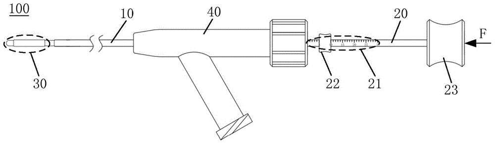
图1是本申请实施例提供的球囊扩张导管的结构示意图;Fig. 1 is a schematic structural view of a balloon dilatation catheter provided by an embodiment of the present application;
图2是本申请实施例提供的导管结构示意图;Fig. 2 is a schematic diagram of the catheter structure provided by the embodiment of the present application;
图3是本申请实施例提供的球囊头的剖面示意图;Fig. 3 is a schematic cross-sectional view of the balloon head provided by the embodiment of the present application;
图4是本申请实施例提供的球囊头的自然状态图;Fig. 4 is a natural state diagram of the balloon head provided by the embodiment of the present application;
图5是本申请实施例提供的球囊头的充盈状态图;Fig. 5 is a diagram of the filling state of the balloon head provided by the embodiment of the present application;
图6是本申请实施例提供的三通管的结构示意图;Fig. 6 is a structural schematic diagram of a tee pipe provided in an embodiment of the present application;
图7是本申请实施例提供的三通管的剖面示意图,示出了三通管在球囊扩张导管上的组装关系;Fig. 7 is a schematic cross-sectional view of the three-way tube provided by the embodiment of the present application, showing the assembly relationship of the three-way tube on the balloon dilation catheter;
图8是本申请实施例提供的球囊扩张导管的使用示意图。Fig. 8 is a schematic diagram of the use of the balloon dilatation catheter provided by the embodiment of the present application.
附图标记说明:Explanation of reference signs:
100.球囊扩张导管;10.导管;11.导向通道;111.近端端孔;112.远端端孔;12.注液通道;121.注液口;122.排液口;20.推杆;21.指示杆;22.限位件;23.手柄;30.球囊头;31.探头;32.球囊;33.弹性元件;34.压扣;40.三通管;41.连接管;42.导通管;43.注液管;44.密封端盖;45.密封圈;200.注射器;300.脑室镜;310.引导通道;A.脑室;B.第三脑室;C.第三脑室底膜;D.基底动脉。100. Balloon dilation catheter; 10. Catheter; 11. Guide channel; 111. Proximal end hole; 112. Distal end hole; 12. Injection channel; 121. Injection port; 122. Drainage port; 20. Push rod; 21. Indicator rod; 22. Limiting piece; 23. Handle; 30. Balloon head; 31. Probe; 32. Balloon; 33. Elastic element; 34. Press buckle; 40. Tee pipe; 41 .Connecting tube; 42. Conducting tube; 43. Injection tube; 44. Sealing end cap; 45. Sealing ring; 200. Syringe; 300. Ventriculoscope; 310. Guide channel; A. Ventricle; B. Third ventricle ; C. The endometrium of the third ventricle; D. The basilar artery.
具体实施方式Detailed ways
下面结合具体实施例对本申请进行详细说明,应该强调的是,下述说明仅仅是示例性的,而不是为了限制本申请的范围及其应用。The present application will be described in detail below in conjunction with specific embodiments. It should be emphasized that the following description is only illustrative, and not intended to limit the scope of the present application and its application.
需要说明的是,除非另有明确的规定和限定,本说明书所使用的术语“中心”、“纵向”、“横向”、“上”、“下”、“竖直”、“水平”、“内”、“外”等指示的方位或位置关系为基于附图所示的方位或位置关系,仅是为了便于描述本申请和简化描述,而不是指示或暗示所指的装置或元件必须具有特定的方位、以特定的方位构造和操作,因此不能理解为对本申请的限制。术语“安装”、“相连”、“连接”、“固定”等术语应做广义理解,例如,可以是固定连接,也可以是可拆卸连接,或一体地连接;可以是机械连接,也可以是电连接;可以是直接相连,也可以通过中间媒介间接相连。此外,术语“第一”、“第二”仅用于描述目的,而不能理解为指示或暗示相对重要性或者隐含指明所指示的技术特征的数量;由此,限定有“第一”、“第二”的特征可以明示或者隐含地包括一个或者更多个该特征;“多个”的含义是两个或两个以上;“和/或”包括一个或多个相关的所列项目的任意的和所有的组合。对于本领域的普通技术人员而言,可以根据具体情况理解上述术语在本申请中的具体含义。It should be noted that, unless otherwise clearly specified and limited, the terms "central", "vertical", "transverse", "upper", "lower", "vertical", "horizontal", " The orientation or positional relationship indicated by "inner", "outer", etc. is based on the orientation or positional relationship shown in the drawings, which is only for the convenience of describing the application and simplifying the description, rather than indicating or implying that the referred device or element must have a specific orientation, are constructed and operate in a particular orientation and therefore are not to be construed as limitations on this application. The terms "mounted", "connected", "connected", "fixed" and other terms should be interpreted in a broad sense, for example, it may be fixed connection, detachable connection, or integral connection; it may be mechanical connection or Electrical connection; either directly or indirectly through an intermediary. In addition, the terms "first" and "second" are only used for descriptive purposes, and cannot be understood as indicating or implying relative importance or implicitly indicating the number of indicated technical features; thus, the definitions of "first", "second" The feature of "second" can expressly or implicitly include one or more of these features; the meaning of "plurality" is two or more; "and/or" includes one or more related listed items Any and all combinations of . Those of ordinary skill in the art can understand the specific meanings of the above terms in this application according to specific situations.
如图1,本申请提供的球囊扩张导管100,包括:管体、推杆20以及球囊头30。As shown in FIG. 1 , the
管体包括导管10,导管10设有近端端孔111和远端端孔112,以及连通近端端孔111和远端端孔112的导向通道11。The tube body includes a
推杆20活动装配于导向通道11内,并且,推杆20的近端伸出近端端孔111,推杆20的远端伸出远端端孔112。The
球囊头30的两端分别连接于导管10的远端和推杆20的远端。本申请实施例中,球囊头30的两端分别弹性连接于导管10的远端和推杆20的远端,当球囊头30抵接于障碍表面时可发生弹性压缩,当解除抵接于障碍表面后可发生弹性复位,以及,推杆20在外力F的推动下可使球囊头30前伸,并且限制球囊头30的前伸长度在预设的长度范围内。Two ends of the
应当说明的是,在医疗行业领域中针对针状类、管状类的医疗器械,通常将其两个末端分别称为近端和远端,其中,近端是指靠近操作者的一端,相应地,远端是指远离操作者的另一端。It should be noted that in the field of medical industry, for needle-shaped and tubular medical devices, the two ends are usually referred to as the proximal end and the distal end respectively, wherein the proximal end refers to the end close to the operator, and accordingly , the far end refers to the other end away from the operator.
本申请通过在球囊扩张导管100的远端设置当碰到障碍时可发生弹性压缩、当解除抵接于障碍后可发生弹性复位的球囊头30,可有效避免操作者在使用球囊扩张导管100对患者的颅脑进行手术的过程中,球囊扩张导管100的远端刺伤或划伤患者的大脑组织,保障手术安全地进行。In this application, by setting the
如图2,导管10还设有注液通道12,注液通道12独立于导向通道11并且沿着导管10的长度方向延伸设置。As shown in FIG. 2 , the
具体的,导管10可以是两端开口内部中空的管状部件,导管10的内部中空部分为径向尺寸大于推杆20的径向尺寸的主通道,该主通道作为导向通道11。在导管10的管壁上,从近端沿着导管10的长度方向往远端的方向上可以开设有至少一条副通道,副通道作为注液通道12。Specifically, the
或者,在一些实施例中,导管10的内部中空部分设置有从近端沿着导管10的长度方向往远端延伸设置的隔板,隔板将导管10的内部中空部分至少一分为二,形成至少两个相对独立设置的通道,其中一条通道的径向尺寸设置为大于推杆20的径向尺寸,用于作为导向通道11,另外一条通道作为注液通道12。Alternatively, in some embodiments, the inner hollow part of the
注液通道12设有与注液通道12相连通的注液口121和排液口122。其中,注液口121可设置于导管10近端的端面和/或侧壁,供外界充盈液体灌注以进入注液通道12,排液口122可设置于导管10远端的端面和/或侧壁,供进入注液通道12内的充盈液体排出。The
如图3,球囊头30可包括探头31、球囊32以及弹性元件33。其中,探头31固定连接于推杆20的远端。球囊32的两端开口、内部中空,球囊32的远端被密封套接于探头31,球囊32的近端被密封套接于导管10的远端,从而围成可与注液通道12、导向通道11相通并且可容纳充盈液体的膨胀腔。弹性元件33可被压缩,位于膨胀腔内并套设于推杆20,两端分别连接探头31的近端以及导管10的远端,以使探头31与导管10之间构成弹性连接。As shown in FIG. 3 , the
本申请实施例中,探头31可以采用不锈钢材质制造。探头31的近端可通过医用胶水或者螺纹结构等合适的连接方式固定于推杆20的远端,探头31上相离于推杆20的远端可被设计成型为圆锥状,即探头31的头部可被设计成型为圆锥状,该圆锥形设计不仅能够增强球囊扩展导管100在穿刺通道内的畅通性能,还便于探头31进入颅脑内部进行穿刺造瘘。应当说明的是,上述探头31的近端是指探头31上与推杆20的远端连接的末端,相应地,为便于说明书的描述,将探头31上相离于推杆20的另外一端称为探头31的远端。In the embodiment of the present application, the
球囊32的两端开口、内部中空。为便于说明书的描述,本申请说明书中将球囊32上靠近导管10的远端的末端称为球囊32的近端,将球囊32上靠近探头31的近端的末端称为球囊32的远端。相应地,设于球囊32的近端的开口称为近端开口,设于球囊32的远端的开口称为球囊32的远端开口。球囊32的远端开口可通过使用医用胶水被密封套接于探头31的近端表面,球囊32的近端开口同样可以通过使用医用胶水被密封套接于导管10的远端表面,以在球囊扩张导管100的远端构成可同时与注液通道12和导向通道11相通的膨胀腔。Both ends of the balloon 32 are open and the inside is hollow. For the convenience of description, the end of the balloon 32 close to the distal end of the
球囊32可采用具有弹力性能的医疗球囊胶制造,例如,在一些实施例中,球囊32可以采用尼龙材料或者聚对苯二甲酸乙二醇酯(Polyethylene terephthalate,PET)材料制造。如图4,球囊32上靠近两端开口的两边的弹性形变可设计成强于两端之间的中部的弹性形变,以使球囊32在充盈液体的充盈下膨胀成型为图5所示出的两边胀大中间收缩的外形,例如梨形、葫芦形或者腰形,确保球囊32在充盈膨胀后可完全包覆探头31,使探头31的头部不伸出球囊32的远端,防止探头31的头部接触并伤及脑组织,具有很好的保护效果。The balloon 32 can be made of elastic medical balloon glue, for example, in some embodiments, the balloon 32 can be made of nylon or polyethylene terephthalate (PET) material. As shown in Figure 4, the elastic deformation of the two sides of the balloon 32 close to the openings at both ends can be designed to be stronger than the elastic deformation of the middle part between the two ends, so that the balloon 32 is inflated and shaped as shown in Figure 5 when filled with liquid. The outer two sides expand and the middle shrinks, such as pear-shaped, gourd-shaped or waist-shaped, to ensure that the balloon 32 can completely cover the
弹性元件33可以采用弹簧,弹簧被收容于膨胀腔内,并且弹簧的两端可以通过使用医用胶水分别粘接固定于探头31和导管10,使球囊头30被弹性连接于导管10的远端,确保球囊头30的柔软性,从而减缓球囊扩张导管100的远端在进入颅脑内之后对脑组织产生的刺激。The
请继续参阅图3,为加强球囊头30与导管10之间的连接效果,球囊32在使用胶水粘接固定于导管10远端的基础上,还可以通过使用压扣34被进一步压接固定于导管10的远端,以防止手术操作过程中球囊头30从导管10上意外脱落。具体的,压扣34可以采用金属制造并可被成型为片状或者丝状。导管10远端的外径可被设置成小于导管10其余部分的外径,以在导管10远端形成可供球囊32黏接的粘附表面,球囊32近端被粘接固定于该粘附表面后,通过使用片状的压扣34包围粘附表面或者使用丝状的压扣34缠绕粘附表面,可将球囊32压接固定,使球囊头30被进一步固定于导管10的远端,大大地降低了球囊头30出现松脱的情况。Please continue to refer to FIG. 3 , in order to strengthen the connection effect between the
如图6,管体还包括三通管40,三通管40设有连接管41、导通管42和注液管43。在三通管40中,连接管41和导通管42同轴设置,注液管43与连接管41和/或导通管42非同轴设置,三通管40以连接管41套接于导管10近端,通过导通管42连通导向通道11,通过注液管43连通注液通道12,并且,为避免充盈液体从连接处渗漏,可在连接管41与导管10的连接处以及在导通管42与推杆20的连接处采用合适的密封结构来确保密封效果。As shown in FIG. 6 , the pipe body further includes a three-
如图7,本申请实施例中,导通管42的管口可拆地装配有密封端盖44以及密封圈45。密封端盖44开设有连通导通管42的导通口,密封端盖44可拆地装配于导通管42的管口,密封圈45装配于在导通管42的管口与密封端盖44之间。在实际使用过程中,推杆20穿过密封端盖44的导通口后通过密封圈45在导通管42的管口中形成密封连接,以在推杆20和导通管42之间构成密封连接。As shown in FIG. 7 , in the embodiment of the present application, the nozzle of the
在一些实施例中,也可通过其他合适的结构替代密封端盖44来达到推杆20与导通管42之间的密封连接效果,例如,可在导通管42的管口边沿设置朝推杆20延伸设置的可供推杆20穿过的环形周缘(图中未示出),导通管42的管口内壁开设有密封槽,密封圈45装配于该密封槽内,协助环形周缘确保推杆20在导通管42的管口处的密封效果。In some embodiments, the sealed connection effect between the
如图8,操作者在使用球囊扩张导管100的过程中,将注射器200连通三通管40的注液管43,接着逐渐推动注射器200的活塞杆以将注射器200内的充盈液体从注液管43注入球囊扩张导管100的内部。充盈液体进入注液管43之后,充盈液体沿着注液通道12流入球囊头30的膨胀腔内,随着充盈液体被不断地注入,充盈液体将充盈整个膨胀腔,接着沿着导向通道11自球囊扩张导管100的远端往近端的方向上逐渐充盈球囊扩张导管100内部的所有空间。由于球囊扩张导管100的内部为密封空间,并且球囊32两边的弹性形变强于球囊32中部的弹性形变,故而当充盈液体充满整个球囊扩张导管100的内部空间后,球囊头30将在继续注入的充盈液体的充盈下膨胀成型为中间凹陷、两端鼓起的外形,充盈膨胀后的球囊32可完全包覆探头31,使探头31的头部不伸出球囊32的远端,避免伤及颅脑内部组织。As shown in Fig. 8, during the process of using the
请参阅图1,为便于了解和控制手术操作过程中球囊头30在人体颅脑内的可伸缩长度,确保手术过程安全可靠地进行,推杆20的近端可被设置成指示杆21,指示杆21的杆体表面可标注有预设范围的刻度。优选的,本申请实施例中指示杆21的刻度范围可以是-10mm-20mm,可以理解的是,本领域技术人员可以根据实际情况将指示杆21的刻度范围设置成其他合理的数值。Please refer to FIG. 1 , in order to facilitate the understanding and control of the retractable length of the
在实际使用中,推杆20在没有受到外力F作用的状态下,指示杆21的0刻度与导通管42的管口边沿对齐。当球囊头30抵接到障碍表面被压缩时,指示杆21的0刻度伸出管口,此时导通管42的管口边沿在指示杆21的杆体上所对齐的刻度值即是球囊头30被压缩的长度。当推动推杆20时,推杆20带动球囊头30实现向远端前伸,指示杆21的0刻度伸入管口后,导通管42的管口边沿在指示杆21的杆体上所对齐的刻度值即是球囊头30由不受外力F作用的自然状态被拉长后的前伸长度,在此过程中,弹性元件33被拉伸,积蓄弹性势能产生复位力,当撤销作用于推杆20的外力F后,推杆20在弹性元件33的复位力下可以重新回归至以0刻度与导通管42的管口边沿对齐的初始位置。In actual use, when the
本申请通过将推杆20的近端设计成为具有一定刻度范围的指示杆21,操作者通过该指示杆21的刻度可以方便地了解球囊头30在人体颅脑内的压缩长度和前伸长度,确保球囊头30的形变在允许的安全范围内,保证手术安全可靠。In this application, the proximal end of the
请参阅图1,推杆20还可设置有限位件22,用于限制球囊头30的前伸长度在预设的安全长度范围内变动。限位件22可以是外形为环形或者正多边形的部件,限位件22的中间开设有装配通孔,限位件22通过装配通孔套设于指示杆21并固定于指示杆21上的目标位置,配合标注于指示杆21表面的刻度来限制推杆20的推动行程,使球囊头30在推杆20作用下的前伸长度被限定于预设的安全长度范围内。Please refer to FIG. 1 , the
进一步的,为确保限位件22在指示杆21上的固定效果,在一些实施例中,限位件22沿着其径向可开设有与装配通孔相通的螺纹通道,螺纹通道内装配有螺柱。当限位件22套设于指示杆21并滑动至目标位置后,旋拧螺柱使螺柱的末端朝向装配通孔的方向移动并抵接于指示杆21的表面,便可将限位件22固定于指示杆21上的目标位置。Further, in order to ensure the fixing effect of the limiting
在实际使用球囊扩张导管100的过程中,通过将限位件22沿着指示杆21移动至目标刻度并固定于该目标刻度后,便可以设置出球囊头30的目标前伸长度,当需要改变球囊头30的前伸长度时,通过将限位件22沿着指示杆21滑动并固定于另一目标刻度后,便可以预先设置出球囊头30的另一目标前伸长度。During the actual use of the
操作者在使用球囊扩张导管100时,通过按压推杆20的近端便可使球囊32向远端做前伸运动,当固定于推杆20的限位件22与装配于导通管42的密封端盖44或者环形周缘抵接后,便可以让球囊头30向前伸出预设的前伸长度,同时起到限制球囊头30继续前伸的效果。当松开推杆20的近端,弹性元件33复位,球囊头30将在弹性元件33的复位力下回缩。同时,限位件22还可防止球囊头30压缩时刺破脑膜瞬间复位,前伸过长而损伤肌底动脉等脑组织。When the operator uses the
请继续参阅图1,为提高操作者在使用球囊扩张导管100时的舒适度,提高操作时的便捷性、可靠性,推杆20的近端可以设置有手柄23。具体的,推杆20的近端可以预先加工出外螺纹,手柄23的中心可以预先加工出与外螺纹相适配的内螺纹,手柄23的内螺纹与推杆20的外螺纹相互配合而实现可拆卸的装配固定。Please continue to refer to FIG. 1 , in order to improve the operator's comfort when using the
本领域技术人员可以理解的是,手柄23与推杆20之间的连接并不仅限于通过上述螺纹结构连接,还可以采用其他任何合适的连接方式实现可靠的装配固定,只要能够确保在使用球囊扩张导管100的过程中手柄23与推杆20之间无相对滑动即可。本申请通过在推杆20的近端设置手柄23,于操作者而言能够更好地对推杆20施力,从而更好地操控球囊头30的拉伸长度,有利于更好地完成手术操作,降低操作风险。Those skilled in the art can understand that the connection between the
为便于更好地理解球囊扩张导管100的实施方式,以下结合实际应用场景对球囊扩张导管100的使用过程作以下示意性说明。In order to better understand the implementation of the
请参阅图8,本实施例的球囊扩张导管100在具体操作时,患者全身麻醉后取平卧位,经MRI准确定位。取冠状缝前1~2cm,中线旁右侧2~3cm为中心,在此作长约3cm的直切口,依次将皮肤、皮下和帽状腱膜切开,对颅骨钻孔,使骨窗扩大到1cm。电凝硬膜止血,对硬膜进行十字切开,电凝脑表面蛛网膜。通过脑穿针垂直于两外耳道连线进行穿刺,穿刺完成后放入脑室镜300,通过脑室镜300显示屏实时观察脑室A额角,对脑室A侧壁的各个方向进行检查,缓慢向前移动循脉络丛,找到室间孔,脑室镜300的引导管10穿过室间孔到达第三脑室B。Please refer to FIG. 8 . During the specific operation of the
到达第三脑室B后使用脑室镜300检查脑室侧壁,垂直方向抵达第三脑室底膜C找到乳头体,使用球囊扩张导管100穿过脑室镜300的引导通道310,于漏斗隐窝和双侧乳头体之间的薄弱区通过球囊头30的探头31穿刺造瘘。具体为:调整限位件22在指示杆21的位置,例如,将限位件22滑动至指示杆刻度处,将球囊扩张导管100以探头31压在第三脑室底膜C,当球囊扩张导管100的探头31受压时,球囊头30内的弹簧被压缩,指示杆21后端的刻度不断退出导通管42的管口以实时显示弹簧被压缩的程度,优选的安全范围为不超过-5mm刻度,当弹簧被继续压缩时,球囊头30前端的探头31在弹簧弹力的作用下刺破第三脑室底膜C,通过脑室镜300可观察到第三脑室底膜C被刺破,若第三脑室底膜C未被刺破,可推动推杆20前伸球囊头30以对第三脑室底膜C进行再次穿刺,直至第三脑室底膜C被刺破形成造瘘口,在此过程中,由于限位件22的限位作用,可防止穿刺过程中球囊头30前伸过长而损伤基底动脉D造成颅内出血;在穿刺形成造瘘口后,在脑室镜300下将球囊扩张导管100的球囊头30插入造瘘口中,当球囊头30的球囊32中部与造瘘口处的第三脑室底膜C共面时,推动预先连接着注液管43的注射器200,使注射器200内的充盈液体依次通过注液管43、注液通道12进入球囊头30的膨胀腔内,随着充盈液体的继续注入,充盈液体将充盈整个球囊扩张导管10的内部空间并使球囊32逐渐胀大,膨胀的球囊32将探头31的远端圆锥部分包裹在内(如图8),防止探头31损伤基底动脉D,当继续推动注射器200时,球囊32可膨胀成为两边胀大的外形,使球囊32可被卡在造瘘口中,防止球囊32在扩张造瘘口的过程中意外脱落,继续注入充盈液体以持续扩张造瘘口,直至造瘘口直径为6-8mm。在造瘘完成后,使用注射器200反向抽吸充盈于球囊扩张导管100内部的充盈液体使球囊32收缩,随后取出球囊扩张导管100和脑室镜300,封闭骨孔,最后缝合头皮,包扎切口,至此手术完成。After reaching the third ventricle B, use a
本申请提供的球囊扩张导管100的球囊头30弹性连接于导管10的远端和推杆20的远端,构成球囊扩张导管100的柔软头端,可避免手术过程中对血管和神经的误伤,减少手术并发症,使定位操作更加安全可靠;推杆20的近端设置成可供判断球囊头30伸缩长度的指示杆21,使球囊头30的压缩或者前伸更直观,具体说是推杆20的刻度使球囊头30在组织穿刺时更方便和准确,使组织穿刺更简单、直观、安全。The
以上内容是结合具体/优选的实施方式对本申请作出的进一步详细说明,不能认定本申请的具体实施只限于这些说明。对本领域的普通技术人员来说,在不脱离本申请构思的前提下,还可以做出若干变形和改进,而这些都属于本申请的保护范围。The above content is a further detailed description of the present application in conjunction with specific/preferred implementation modes, and it cannot be considered that the specific implementation of the present application is limited to these descriptions. For those of ordinary skill in the art, without departing from the concept of the present application, several modifications and improvements can be made, and these all belong to the protection scope of the present application.
Claims (10)
Priority Applications (1)
| Application Number | Priority Date | Filing Date | Title |
|---|---|---|---|
| CN202310146151.7A CN116271447B (en) | 2023-02-13 | 2023-02-13 | Balloon dilation catheter |
Applications Claiming Priority (1)
| Application Number | Priority Date | Filing Date | Title |
|---|---|---|---|
| CN202310146151.7A CN116271447B (en) | 2023-02-13 | 2023-02-13 | Balloon dilation catheter |
Publications (2)
| Publication Number | Publication Date |
|---|---|
| CN116271447A true CN116271447A (en) | 2023-06-23 |
| CN116271447B CN116271447B (en) | 2025-09-09 |
Family
ID=86786156
Family Applications (1)
| Application Number | Title | Priority Date | Filing Date |
|---|---|---|---|
| CN202310146151.7A Active CN116271447B (en) | 2023-02-13 | 2023-02-13 | Balloon dilation catheter |
Country Status (1)
| Country | Link |
|---|---|
| CN (1) | CN116271447B (en) |
Cited By (2)
| Publication number | Priority date | Publication date | Assignee | Title |
|---|---|---|---|---|
| CN119405361A (en) * | 2024-12-30 | 2025-02-11 | 中南大学湘雅二医院 | A double-lumen Myers balloon dilatation catheter |
| CN119791799A (en) * | 2025-01-20 | 2025-04-11 | 苏州海宇新辰医疗科技有限公司 | Atrial septal puncture kit |
Citations (9)
| Publication number | Priority date | Publication date | Assignee | Title |
|---|---|---|---|---|
| US20130197563A1 (en) * | 2002-09-30 | 2013-08-01 | Advanced Polymers, Inc. | Apparatus and methods for treating bone structures, tissues and ducts using a narrow gauge cannula system |
| WO2015069089A1 (en) * | 2013-11-11 | 2015-05-14 | 안용철 | Balloon catheter |
| WO2019166208A1 (en) * | 2018-02-27 | 2019-09-06 | Segers Bernard | System for deploying a vascular bypass prosthesis |
| JPWO2020240717A1 (en) * | 2019-05-28 | 2020-12-03 | ||
| CN112274762A (en) * | 2020-11-18 | 2021-01-29 | 上海翰凌医疗器械有限公司 | Balloon expanding device |
| CN215079135U (en) * | 2021-03-19 | 2021-12-10 | 徐世保 | T-shaped balloon dilator |
| CN114886628A (en) * | 2022-05-17 | 2022-08-12 | 恒壹(北京)医疗科技有限公司 | Self-expansion balloon catheter and use method thereof |
| CN115300766A (en) * | 2022-08-31 | 2022-11-08 | 优尔爱(常州)医疗科技有限公司 | Eustachian tube saccule and implanting device |
| CN219539204U (en) * | 2023-02-13 | 2023-08-18 | 深圳市擎源医疗器械有限公司 | Balloon dilation catheter |
-
2023
- 2023-02-13 CN CN202310146151.7A patent/CN116271447B/en active Active
Patent Citations (9)
| Publication number | Priority date | Publication date | Assignee | Title |
|---|---|---|---|---|
| US20130197563A1 (en) * | 2002-09-30 | 2013-08-01 | Advanced Polymers, Inc. | Apparatus and methods for treating bone structures, tissues and ducts using a narrow gauge cannula system |
| WO2015069089A1 (en) * | 2013-11-11 | 2015-05-14 | 안용철 | Balloon catheter |
| WO2019166208A1 (en) * | 2018-02-27 | 2019-09-06 | Segers Bernard | System for deploying a vascular bypass prosthesis |
| JPWO2020240717A1 (en) * | 2019-05-28 | 2020-12-03 | ||
| CN112274762A (en) * | 2020-11-18 | 2021-01-29 | 上海翰凌医疗器械有限公司 | Balloon expanding device |
| CN215079135U (en) * | 2021-03-19 | 2021-12-10 | 徐世保 | T-shaped balloon dilator |
| CN114886628A (en) * | 2022-05-17 | 2022-08-12 | 恒壹(北京)医疗科技有限公司 | Self-expansion balloon catheter and use method thereof |
| CN115300766A (en) * | 2022-08-31 | 2022-11-08 | 优尔爱(常州)医疗科技有限公司 | Eustachian tube saccule and implanting device |
| CN219539204U (en) * | 2023-02-13 | 2023-08-18 | 深圳市擎源医疗器械有限公司 | Balloon dilation catheter |
Cited By (2)
| Publication number | Priority date | Publication date | Assignee | Title |
|---|---|---|---|---|
| CN119405361A (en) * | 2024-12-30 | 2025-02-11 | 中南大学湘雅二医院 | A double-lumen Myers balloon dilatation catheter |
| CN119791799A (en) * | 2025-01-20 | 2025-04-11 | 苏州海宇新辰医疗科技有限公司 | Atrial septal puncture kit |
Also Published As
| Publication number | Publication date |
|---|---|
| CN116271447B (en) | 2025-09-09 |
Similar Documents
| Publication | Publication Date | Title |
|---|---|---|
| US5957952A (en) | Vascular sealing device | |
| US20080319472A1 (en) | Cervical dilator catheter | |
| US20070288051A1 (en) | Fluid-filled cervical dilator | |
| WO2008027292A2 (en) | Cervical dilator and methods of use | |
| CN109475718A (en) | Safe urinary catheter and method of manufacture | |
| CN116271447A (en) | Balloon dilation catheter | |
| US8123773B1 (en) | Postpartum hemorrhage balloon tamponade catheter | |
| CN219539204U (en) | Balloon dilation catheter | |
| CN219355037U (en) | Fistulization sacculus dilating catheter | |
| CN204698615U (en) | Novel skin dilator | |
| CN107468292B (en) | Varicocele ligatures puncture outfit under a kind of laparoscope | |
| CN116439792A (en) | A puncture needle assembly and balloon dilation catheter device | |
| CN209286272U (en) | Convenient for the percutaneous puncture negative pressure drainage flusher of the abscess of neck of vacuum cavitations | |
| CN116173382A (en) | Fistulization sacculus dilating catheter | |
| CN110840504A (en) | A ureteral occlusion device with a balloon | |
| CN103190944B (en) | Disposable pericardium chest puncture needle | |
| CN205964679U (en) | Device is kept somewhere in nasal sinus drainage | |
| CN111166416B (en) | Lower uterine segment hemostatic structure for cesarean section | |
| CN210277306U (en) | Trocar for treating cystic cirrhosis | |
| CN220877506U (en) | Leakage-proof three-cavity catheter | |
| CN220370042U (en) | Puncture needle assembly and balloon dilation catheter device | |
| CN111419321A (en) | Percutaneous direct puncture type drainage tube through liver and gall bladder | |
| CN106448402B (en) | Balloon model device for simulating intracranial space occupying effect | |
| CN215651380U (en) | A balloon type tourniquet | |
| CN110811785B (en) | A bladder puncture fistula tube and its components and working method |
Legal Events
| Date | Code | Title | Description |
|---|---|---|---|
| PB01 | Publication | ||
| PB01 | Publication | ||
| SE01 | Entry into force of request for substantive examination | ||
| SE01 | Entry into force of request for substantive examination | ||
| GR01 | Patent grant | ||
| GR01 | Patent grant |