CN116269216A - Photoacoustic brain imaging system and method based on PVDF-ITO transparent transducer cranium window - Google Patents
Photoacoustic brain imaging system and method based on PVDF-ITO transparent transducer cranium window Download PDFInfo
- Publication number
- CN116269216A CN116269216A CN202310091895.3A CN202310091895A CN116269216A CN 116269216 A CN116269216 A CN 116269216A CN 202310091895 A CN202310091895 A CN 202310091895A CN 116269216 A CN116269216 A CN 116269216A
- Authority
- CN
- China
- Prior art keywords
- transparent
- photoacoustic
- transducer
- pvdf
- arc
- Prior art date
- Legal status (The legal status is an assumption and is not a legal conclusion. Google has not performed a legal analysis and makes no representation as to the accuracy of the status listed.)
- Pending
Links
- 238000002610 neuroimaging Methods 0.000 title claims abstract description 40
- 238000000034 method Methods 0.000 title claims description 10
- 238000003384 imaging method Methods 0.000 claims abstract description 65
- 210000004556 brain Anatomy 0.000 claims abstract description 32
- 239000000463 material Substances 0.000 claims abstract description 31
- 239000002033 PVDF binder Substances 0.000 claims abstract description 27
- 239000003822 epoxy resin Substances 0.000 claims abstract description 27
- 229920000647 polyepoxide Polymers 0.000 claims abstract description 27
- 229920002981 polyvinylidene fluoride Polymers 0.000 claims abstract description 27
- 230000003287 optical effect Effects 0.000 claims abstract description 24
- 230000005284 excitation Effects 0.000 claims abstract description 18
- 238000012545 processing Methods 0.000 claims abstract description 18
- BQCADISMDOOEFD-UHFFFAOYSA-N Silver Chemical compound [Ag] BQCADISMDOOEFD-UHFFFAOYSA-N 0.000 claims abstract description 13
- 210000004761 scalp Anatomy 0.000 claims abstract description 7
- 238000001514 detection method Methods 0.000 claims abstract description 5
- 210000003625 skull Anatomy 0.000 claims description 51
- 239000010410 layer Substances 0.000 claims description 42
- 239000013307 optical fiber Substances 0.000 claims description 15
- 210000001519 tissue Anatomy 0.000 claims description 12
- 238000013461 design Methods 0.000 claims description 11
- 238000002360 preparation method Methods 0.000 claims description 10
- 229910001220 stainless steel Inorganic materials 0.000 claims description 9
- 239000010935 stainless steel Substances 0.000 claims description 9
- 238000001914 filtration Methods 0.000 claims description 8
- MRNHPUHPBOKKQT-UHFFFAOYSA-N indium;tin;hydrate Chemical compound O.[In].[Sn] MRNHPUHPBOKKQT-UHFFFAOYSA-N 0.000 claims description 8
- 230000007774 longterm Effects 0.000 claims description 8
- 238000003199 nucleic acid amplification method Methods 0.000 claims description 8
- 238000002834 transmittance Methods 0.000 claims description 8
- 230000003321 amplification Effects 0.000 claims description 7
- IJVRPNIWWODHHA-UHFFFAOYSA-N 2-cyanoprop-2-enoic acid Chemical compound OC(=O)C(=C)C#N IJVRPNIWWODHHA-UHFFFAOYSA-N 0.000 claims description 5
- 230000000877 morphologic effect Effects 0.000 claims description 5
- 238000010171 animal model Methods 0.000 claims description 4
- 239000003479 dental cement Substances 0.000 claims description 4
- 239000004205 dimethyl polysiloxane Substances 0.000 claims description 4
- 235000013870 dimethyl polysiloxane Nutrition 0.000 claims description 4
- CXQXSVUQTKDNFP-UHFFFAOYSA-N octamethyltrisiloxane Chemical compound C[Si](C)(C)O[Si](C)(C)O[Si](C)(C)C CXQXSVUQTKDNFP-UHFFFAOYSA-N 0.000 claims description 4
- 238000004987 plasma desorption mass spectroscopy Methods 0.000 claims description 4
- 229920000435 poly(dimethylsiloxane) Polymers 0.000 claims description 4
- 239000011241 protective layer Substances 0.000 claims description 4
- 230000035945 sensitivity Effects 0.000 claims description 4
- 239000003795 chemical substances by application Substances 0.000 claims description 3
- 230000035790 physiological processes and functions Effects 0.000 claims description 3
- 238000004382 potting Methods 0.000 claims description 3
- 238000004140 cleaning Methods 0.000 claims description 2
- 239000002504 physiological saline solution Substances 0.000 claims description 2
- 238000005498 polishing Methods 0.000 claims description 2
- LWUVWAREOOAHDW-UHFFFAOYSA-N lead silver Chemical compound [Ag].[Pb] LWUVWAREOOAHDW-UHFFFAOYSA-N 0.000 claims 5
- 238000007428 craniotomy Methods 0.000 claims 2
- 238000007789 sealing Methods 0.000 claims 2
- 206010061218 Inflammation Diseases 0.000 claims 1
- 239000000853 adhesive Substances 0.000 claims 1
- 230000001070 adhesive effect Effects 0.000 claims 1
- 239000003364 biologic glue Substances 0.000 claims 1
- 230000023597 hemostasis Effects 0.000 claims 1
- 230000013632 homeostatic process Effects 0.000 claims 1
- 230000002093 peripheral effect Effects 0.000 claims 1
- 230000007306 turnover Effects 0.000 claims 1
- 230000006870 function Effects 0.000 abstract description 4
- 230000009977 dual effect Effects 0.000 abstract description 2
- 229910052709 silver Inorganic materials 0.000 abstract 1
- 239000004332 silver Substances 0.000 abstract 1
- 230000026683 transduction Effects 0.000 abstract 1
- 238000010361 transduction Methods 0.000 abstract 1
- 239000000835 fiber Substances 0.000 description 22
- 239000000243 solution Substances 0.000 description 13
- 238000012634 optical imaging Methods 0.000 description 7
- 210000004204 blood vessel Anatomy 0.000 description 6
- 238000010586 diagram Methods 0.000 description 6
- 238000011160 research Methods 0.000 description 6
- 238000005516 engineering process Methods 0.000 description 4
- 238000012014 optical coherence tomography Methods 0.000 description 4
- 238000012285 ultrasound imaging Methods 0.000 description 4
- 230000006378 damage Effects 0.000 description 3
- 238000011161 development Methods 0.000 description 3
- 238000012544 monitoring process Methods 0.000 description 3
- 230000003110 anti-inflammatory effect Effects 0.000 description 2
- 230000003925 brain function Effects 0.000 description 2
- 210000003710 cerebral cortex Anatomy 0.000 description 2
- 230000001684 chronic effect Effects 0.000 description 2
- 210000001951 dura mater Anatomy 0.000 description 2
- 230000000694 effects Effects 0.000 description 2
- 239000003292 glue Substances 0.000 description 2
- 230000002439 hemostatic effect Effects 0.000 description 2
- 210000000987 immune system Anatomy 0.000 description 2
- 210000005036 nerve Anatomy 0.000 description 2
- 238000010146 3D printing Methods 0.000 description 1
- 108010027529 Bio-glue Proteins 0.000 description 1
- 238000001069 Raman spectroscopy Methods 0.000 description 1
- FAPWRFPIFSIZLT-UHFFFAOYSA-M Sodium chloride Chemical compound [Na+].[Cl-] FAPWRFPIFSIZLT-UHFFFAOYSA-M 0.000 description 1
- 238000010521 absorption reaction Methods 0.000 description 1
- 210000003484 anatomy Anatomy 0.000 description 1
- 238000000149 argon plasma sintering Methods 0.000 description 1
- 230000009286 beneficial effect Effects 0.000 description 1
- 239000002639 bone cement Substances 0.000 description 1
- 210000005013 brain tissue Anatomy 0.000 description 1
- 230000002490 cerebral effect Effects 0.000 description 1
- 206010008129 cerebral palsy Diseases 0.000 description 1
- 208000026106 cerebrovascular disease Diseases 0.000 description 1
- 238000004891 communication Methods 0.000 description 1
- 239000002131 composite material Substances 0.000 description 1
- 239000004020 conductor Substances 0.000 description 1
- 239000013078 crystal Substances 0.000 description 1
- 201000010099 disease Diseases 0.000 description 1
- 208000037265 diseases, disorders, signs and symptoms Diseases 0.000 description 1
- 238000009826 distribution Methods 0.000 description 1
- 239000007772 electrode material Substances 0.000 description 1
- 230000003631 expected effect Effects 0.000 description 1
- 208000015181 infectious disease Diseases 0.000 description 1
- 230000028709 inflammatory response Effects 0.000 description 1
- 238000009434 installation Methods 0.000 description 1
- 230000003993 interaction Effects 0.000 description 1
- GQYHUHYESMUTHG-UHFFFAOYSA-N lithium niobate Chemical compound [Li+].[O-][Nb](=O)=O GQYHUHYESMUTHG-UHFFFAOYSA-N 0.000 description 1
- 238000005259 measurement Methods 0.000 description 1
- 210000004088 microvessel Anatomy 0.000 description 1
- 238000012986 modification Methods 0.000 description 1
- 230000004048 modification Effects 0.000 description 1
- 230000035515 penetration Effects 0.000 description 1
- 239000000523 sample Substances 0.000 description 1
- 239000011780 sodium chloride Substances 0.000 description 1
- 238000001228 spectrum Methods 0.000 description 1
- 238000006467 substitution reaction Methods 0.000 description 1
- 238000000482 two photon fluorescence microscopy Methods 0.000 description 1
- 238000002604 ultrasonography Methods 0.000 description 1
- 230000002792 vascular Effects 0.000 description 1
Images


Classifications
-
- A—HUMAN NECESSITIES
- A61—MEDICAL OR VETERINARY SCIENCE; HYGIENE
- A61B—DIAGNOSIS; SURGERY; IDENTIFICATION
- A61B5/00—Measuring for diagnostic purposes; Identification of persons
- A61B5/0093—Detecting, measuring or recording by applying one single type of energy and measuring its conversion into another type of energy
- A61B5/0095—Detecting, measuring or recording by applying one single type of energy and measuring its conversion into another type of energy by applying light and detecting acoustic waves, i.e. photoacoustic measurements
-
- A—HUMAN NECESSITIES
- A61—MEDICAL OR VETERINARY SCIENCE; HYGIENE
- A61B—DIAGNOSIS; SURGERY; IDENTIFICATION
- A61B90/00—Instruments, implements or accessories specially adapted for surgery or diagnosis and not covered by any of the groups A61B1/00 - A61B50/00, e.g. for luxation treatment or for protecting wound edges
- A61B90/36—Image-producing devices or illumination devices not otherwise provided for
- A61B90/37—Surgical systems with images on a monitor during operation
-
- Y—GENERAL TAGGING OF NEW TECHNOLOGICAL DEVELOPMENTS; GENERAL TAGGING OF CROSS-SECTIONAL TECHNOLOGIES SPANNING OVER SEVERAL SECTIONS OF THE IPC; TECHNICAL SUBJECTS COVERED BY FORMER USPC CROSS-REFERENCE ART COLLECTIONS [XRACs] AND DIGESTS
- Y02—TECHNOLOGIES OR APPLICATIONS FOR MITIGATION OR ADAPTATION AGAINST CLIMATE CHANGE
- Y02A—TECHNOLOGIES FOR ADAPTATION TO CLIMATE CHANGE
- Y02A50/00—TECHNOLOGIES FOR ADAPTATION TO CLIMATE CHANGE in human health protection, e.g. against extreme weather
- Y02A50/30—Against vector-borne diseases, e.g. mosquito-borne, fly-borne, tick-borne or waterborne diseases whose impact is exacerbated by climate change
Landscapes
- Health & Medical Sciences (AREA)
- Life Sciences & Earth Sciences (AREA)
- Surgery (AREA)
- Molecular Biology (AREA)
- Animal Behavior & Ethology (AREA)
- Pathology (AREA)
- Engineering & Computer Science (AREA)
- Biomedical Technology (AREA)
- Heart & Thoracic Surgery (AREA)
- Medical Informatics (AREA)
- Physics & Mathematics (AREA)
- Nuclear Medicine, Radiotherapy & Molecular Imaging (AREA)
- Veterinary Medicine (AREA)
- General Health & Medical Sciences (AREA)
- Public Health (AREA)
- Biophysics (AREA)
- Gynecology & Obstetrics (AREA)
- Acoustics & Sound (AREA)
- Radiology & Medical Imaging (AREA)
- Oral & Maxillofacial Surgery (AREA)
- Ultra Sonic Daignosis Equipment (AREA)
Abstract
本发明公开了一种基于PVDF‑ITO透明换能器颅窗的光声脑成像系统及成像方法,系统包括弧形透明换能器、透明换能器颅窗、光声脑成像系统;所述的弧形透明换能器由ITO电极、PVDF压电材料、导线银丝、环氧树脂背衬层以及弧形结构匹配层构成;透明换能器颅窗通过换能器连接环将弧形透明换能器与头皮连接,并进行密封固定;所述的光声脑成像系统包括光学激发扫描模块和信号处理重建模块;其中光学激发扫描模块由二维振镜带动双波长激发光源在透明换能器表面进行非接触快速扫描;信号处理重建模块将换能器颅窗接收到的光声信号还原成光声脑图像。本发明优势在于将透明颅窗转化为一种主动传感装置,实现光学透明成像窗口和超声换能器检测的双重功能。
The invention discloses a photoacoustic brain imaging system and imaging method based on a PVDF‑ITO transparent transducer cranial window. The system includes an arc-shaped transparent transducer, a transparent transducer cranial window, and a photoacoustic brain imaging system; The arc-shaped transparent transducer is composed of ITO electrodes, PVDF piezoelectric materials, wire silver wires, epoxy resin backing layer and arc-shaped structure matching layer; the cranial window of the transparent transducer connects the arc-shaped transparent The transducer is connected to the scalp and sealed and fixed; the photoacoustic brain imaging system includes an optical excitation scanning module and a signal processing and reconstruction module; wherein the optical excitation scanning module is driven by a two-dimensional vibrating mirror to drive a dual-wavelength excitation light source in a transparent transduction The surface of the transducer is scanned quickly without contact; the signal processing and reconstruction module restores the photoacoustic signal received by the cranial window of the transducer into a photoacoustic brain image. The advantage of the invention is that the transparent cranial window is transformed into an active sensing device, and the dual functions of the optically transparent imaging window and ultrasonic transducer detection are realized.
Description
技术领域technical field
本发明涉及光声成像的技术领域,具体涉及一种基于PVDF-ITO透明换能器颅窗的光声脑成像系统及成像方法。The invention relates to the technical field of photoacoustic imaging, in particular to a photoacoustic brain imaging system and imaging method based on a PVDF-ITO transparent transducer cranial window.
背景技术Background technique
颅窗被广泛的应用于双光子荧光显微镜、光学相干层析成像和激光散斑对比成像等传统的光学成像领域。透明成像颅窗不仅能克服颅骨带来的光散射的影响,同时能够保留大脑生理环境,允许对大脑进行长期、直观的成像监测,对大脑功能建立更加全面的了解。光声成像是一种结合了光学成像和超声成像的非侵入式的成像技术,它同时具有光学成像的高对比度、高分辨率和超声成像的高穿透性的特点。光声成像建立在光产生声的基本原理,当用短脉冲激光照射在生物组织上时,生物组织吸收脉冲能量迅速膨胀产生超声,即光声信号,根据光声信号可以重建出反映生物组织结构和功能信息的图像。光声成像克服了一些传统成像方式的缺点,例如:与光学相干层析成像(OCT)相比,由于组织光学强散射性造成OCT的测量深度限制在毫米量级的浅层,而光声成像技术可达厘米量级;与纯超声成像相比,在声阻抗相差不大的区域超声成像的对比度很低,而光声成像则利用不同组织的吸收差异来重建出高对比度的图像。Cranial windows are widely used in traditional optical imaging fields such as two-photon fluorescence microscopy, optical coherence tomography, and laser speckle contrast imaging. The transparent imaging cranial window can not only overcome the influence of light scattering brought by the skull, but also preserve the physiological environment of the brain, allowing long-term and intuitive imaging monitoring of the brain, and establishing a more comprehensive understanding of brain function. Photoacoustic imaging is a non-invasive imaging technology that combines optical imaging and ultrasound imaging. It has the characteristics of high contrast and high resolution of optical imaging and high penetration of ultrasound imaging. Photoacoustic imaging is based on the basic principle that light produces sound. When a short-pulse laser is irradiated on biological tissue, the biological tissue absorbs the pulse energy and expands rapidly to generate ultrasound, that is, the photoacoustic signal. According to the photoacoustic signal, the structure reflecting the biological tissue can be reconstructed. and images of feature information. Photoacoustic imaging overcomes the shortcomings of some traditional imaging methods. For example, compared with optical coherence tomography (OCT), the measurement depth of OCT is limited to shallow layers on the order of millimeters due to the strong optical scattering of tissues, while photoacoustic imaging The technology can reach the centimeter level; compared with pure ultrasound imaging, the contrast of ultrasound imaging is very low in areas where the acoustic impedance is not much different, while photoacoustic imaging uses the absorption difference of different tissues to reconstruct a high-contrast image.
尽管颅窗的发展显著增强了光学脑成像的分辨率,但是随着应用研究的深入发展,基于颅窗的高分辨光学成像受限于密集大脑组织的高散射特性,且受限于颅骨弧度结构的影响。与纯光学成像技术不同的是,在光声成像中,颅窗材料需要同时满足光学透明和声学透明。考虑到光声脑成像中需要同时接收光声信号,因此具有光学透明特性的压电材料是制备光声脑成像的优选方案。本专利中由透明锡-铟氧化物(ITO)电极、聚偏氟乙烯(PVDF)压电材料、环氧树脂背衬以及匹配层制备而成的透明成像颅窗不仅能克服颅骨带来的光散射的影响,同时能够保留大脑生理环境,允许对大脑进行长期、直观的成像监测,对大脑功能建立更加全面的了解。利用透明压电材料制备换能器用于光声成像的研究中,申请号202110861125.3的专利申请公开了一种基于透明柔性复合电极的高灵敏全透明光声探测器及内窥装置,该设计所使用的双面抛光极化的铌酸锂压电晶体材料不如PVDF压电材料柔韧性好,无法匹配颅骨自然解剖学的弧形特征制作换能器颅窗,造成有效检测范围小,无法获取全脑光声成像。利用弧形换能器进行光声成像研究中,申请号202110925648.X的专利申请公开了一种弧形换能器阵列及其制备方法,该方法设计3D打印小型曲面网格模具不如参照颅骨三维模型自主设计匹配颅骨弧度的模具,无法匹配颅骨形态学结构,造成声阻抗的增加,无法提高声学检测灵敏度。在柔性基地曲,面光声成像系统中,申请号201610743856.7的专利申请公开了一种柔性基底MEMS器件曲面阵列光声成像系统,改设计所使用的MEMS声换能器阵列层、柔性印刷电路版互联层、MEMS微镜阵列及光纤通道层不如锡-铟氧化物(ITO)电极、聚偏氟乙烯(PVDF)压电材料以及环氧树脂背衬材料的透光性好,无法达到透光率大于80%,造成光学激发信号的减弱,无法获取高分辨率光声成像。Although the development of cranial windows has significantly enhanced the resolution of optical brain imaging, with the in-depth development of applied research, high-resolution optical imaging based on cranial windows is limited by the high scattering properties of dense brain tissue and the curvature of the skull. Impact. Unlike purely optical imaging techniques, in photoacoustic imaging, cranial window materials need to be both optically transparent and acoustically transparent. Considering that photoacoustic brain imaging needs to receive photoacoustic signals at the same time, piezoelectric materials with optical transparency are the preferred solution for preparing photoacoustic brain imaging. In this patent, the transparent imaging cranial window prepared by transparent tin-indium oxide (ITO) electrodes, polyvinylidene fluoride (PVDF) piezoelectric materials, epoxy resin backing and matching layer can not only overcome the light brought by the skull The effects of scattering, while being able to preserve the physiological environment of the brain, allow for long-term, intuitive imaging monitoring of the brain, building a more comprehensive understanding of brain function. In the research of using transparent piezoelectric materials to prepare transducers for photoacoustic imaging, the patent application with application number 202110861125.3 discloses a highly sensitive fully transparent photoacoustic detector and endoscopic device based on transparent flexible composite electrodes. The design uses The double-sided polished and polarized lithium niobate piezoelectric crystal material is not as flexible as the PVDF piezoelectric material, and cannot match the curved features of the natural anatomy of the skull to make the cranial window of the transducer, resulting in a small effective detection range and unable to obtain the whole brain. Photoacoustic imaging. In the research of photoacoustic imaging using curved transducers, the patent application with application number 202110925648.X discloses a curved transducer array and its preparation method. The design of 3D printed small curved mesh molds by this method is not as good as referring to the three-dimensional skull The model independently designed a mold to match the curvature of the skull, which could not match the morphological structure of the skull, resulting in an increase in acoustic impedance and unable to improve the sensitivity of acoustic detection. In the flexible base curved and surface photoacoustic imaging system, the patent application No. 201610743856.7 discloses a flexible base MEMS device surface array photoacoustic imaging system, and the MEMS acoustic transducer array layer and flexible printed circuit board used in the design are modified. The interconnect layer, MEMS micromirror array and fiber channel layer are not as good as tin-indium oxide (ITO) electrodes, polyvinylidene fluoride (PVDF) piezoelectric materials, and epoxy resin backing materials, and cannot achieve light transmittance If it is greater than 80%, the optical excitation signal will be weakened, and high-resolution photoacoustic imaging cannot be obtained.
发明内容Contents of the invention
本发明的主要目的将透明颅窗技术引入到光声脑成像中,克服在高分辨的光学成像中由于繁杂的手术操作破坏了颅骨引发硬脑膜感染,从而造成颅骨及硬脑膜上丰富的神经与免疫系统损伤的问题,提供了一种基于PVDF-ITO透明换能器颅窗的光声脑成像系统及成像方法,在保证颅骨完整免疫系统的情况下实现对大脑微血管准确长期安全的成像研究,为慢性脑血管疾病的研究提供技术支持。The main purpose of the present invention is to introduce transparent cranial window technology into photoacoustic brain imaging, to overcome the dura mater infection caused by the destruction of the skull due to complicated surgical operations in high-resolution optical imaging, resulting in abundant nerves and nerves on the skull and dura mater. For the problem of immune system damage, a photoacoustic brain imaging system and imaging method based on a PVDF-ITO transparent transducer cranial window is provided to achieve accurate, long-term and safe imaging research on brain microvessels while ensuring the integrity of the skull’s immune system. Provide technical support for research on chronic cerebrovascular diseases.
为了达到上述目的,本发明采用以下技术方案:In order to achieve the above object, the present invention adopts the following technical solutions:
第一方面,本发明提供了一种基于PVDF-ITO透明换能器颅窗的光声脑成像系统,包括弧形透明换能器、透明换能器颅窗和光声脑成像单元,所述弧形透明换能器与透明换能器颅窗连接,脉冲激光经过透明换能器颅窗后在光声脑成像单元中成像,其中:In the first aspect, the present invention provides a photoacoustic brain imaging system based on a PVDF-ITO transparent transducer cranial window, including an arc-shaped transparent transducer, a transparent transducer cranial window, and a photoacoustic brain imaging unit. The shaped transparent transducer is connected with the cranial window of the transparent transducer, and the pulsed laser is imaged in the photoacoustic brain imaging unit after passing through the cranial window of the transparent transducer, wherein:
所述弧形透明换能器由透明锡-铟氧化物ITO电极、聚偏氟乙烯PVDF压电材料、导线银丝、环氧树脂背衬层以及弧形结构匹配层制备而成,并根据颅骨弧形结构进行设计;在不锈钢治具倒置中,依次按顺序放置环氧树脂背衬层、第一导线银丝、设计好的PVDF-ITO压电薄膜、第二导线银丝、匹配层,各个结构层之间涂抹少量的环氧树脂进行固定;所述PVDF-ITO压电薄膜为ITO-PVDF-ITO的夹层薄膜结构;The curved transparent transducer is prepared from transparent tin-indium oxide ITO electrodes, polyvinylidene fluoride PVDF piezoelectric material, wire silver wire, epoxy resin backing layer and curved structure matching layer, and according to the skull The arc structure is designed; in the stainless steel jig upside down, the epoxy resin backing layer, the first wire silver wire, the designed PVDF-ITO piezoelectric film, the second wire silver wire, and the matching layer are placed in sequence. A small amount of epoxy resin is applied between the structural layers for fixing; the PVDF-ITO piezoelectric film is a sandwich film structure of ITO-PVDF-ITO;
所述透明换能器颅窗通过换能器连接环将弧形透明换能器与头皮组织密封结合,保证手术部位的生理状态稳定性且颅窗制备过程中不损伤颅骨结构,透明换能器颅窗提供光学透明成像窗口的同时用于接收光声信号;The cranial window of the transparent transducer seals and combines the arc-shaped transparent transducer with the scalp tissue through the transducer connecting ring, ensuring the stability of the physiological state of the surgical site and not damaging the skull structure during the preparation of the cranial window. The transparent transducer The cranial window provides an optically transparent imaging window and is used to receive photoacoustic signals;
所述光声脑成像单元包括光学激发扫描模块和信号处理重建模块;其中光学激发扫描模块包括顺序连接的532nm激光器、第一光阑、第一光纤耦合器、第一光纤跳线、第一光纤准直器、第一反射镜,顺序连接的1064nm激光器、第二光阑、第二光纤耦合器、第二光纤跳线、第二光纤准直器、第二反射镜,以及二维振镜扫描仪和扫描透镜,所述第一反射镜和第二反射镜连接后与二维振镜扫描仪连接,所述二维振镜扫描仪与扫描透镜连接;所述信号处理重建模块包括顺序连接的前置放大滤波系统、数据采集系统、图像处理器和显示器;信号处理重建模块将透明换能器颅窗接收到的光声信号还原成光声脑图像,经过放大滤波之后重建出高分辨的三维光声脑图像。The photoacoustic brain imaging unit includes an optical excitation scanning module and a signal processing reconstruction module; wherein the optical excitation scanning module includes a sequentially connected 532nm laser, a first aperture, a first fiber coupler, a first fiber jumper, a first optical fiber Collimator, first mirror, sequentially connected 1064nm laser, second aperture, second fiber coupler, second fiber jumper, second fiber collimator, second mirror, and 2D galvanometer scanning instrument and scanning lens, the first mirror and the second mirror are connected to the two-dimensional vibrating mirror scanner, and the two-dimensional vibrating mirror scanner is connected to the scanning lens; the signal processing and reconstruction module includes sequentially connected Pre-amplification and filtering system, data acquisition system, image processor and display; signal processing and reconstruction module restores the photoacoustic signal received by the transparent transducer cranial window into a photoacoustic brain image, and reconstructs a high-resolution three-dimensional image after amplification and filtering Photoacoustic Brain Imaging.
作为优选的技术方案,所述弧形透明换能器的制备过程如下:As a preferred technical solution, the preparation process of the arc-shaped transparent transducer is as follows:
获取目标成像动物模型的颅骨参数,获取高精度的背衬模型,通过翻模的方法获取环氧树脂材料的背衬层;Obtain the skull parameters of the target imaging animal model, obtain a high-precision backing model, and obtain the backing layer of epoxy resin material by turning over the mold;
将环氧树脂背衬层上下表面进行抛光处理增加其光学透过率;Polish the upper and lower surfaces of the epoxy resin backing layer to increase its optical transmittance;
将带有脱模剂的不锈钢治具倒置,依次按顺序放置环氧树脂背衬层、第一导线银丝、PVDF-ITO压电薄膜、第二导线银丝和匹配层,各个结构层之间涂抹少量的环氧树脂进行固定;Turn the stainless steel jig with the release agent upside down, place the epoxy resin backing layer, the first wire silver wire, the PVDF-ITO piezoelectric film, the second wire silver wire and the matching layer in sequence, between each structural layer Apply a small amount of epoxy resin to fix;
匹配层上方加入PDMS保护层后由不锈钢治具压紧后放入保温箱中固化;After the PDMS protective layer is added above the matching layer, it is pressed by a stainless steel fixture and placed in an incubator for curing;
使用灌封胶将固化成型的弧形透明换能器固定到连接环中。Use potting glue to fix the cured curved transparent transducer into the connection ring.
作为优选的技术方案,所述透明换能器颅窗的制备过程如下:As a preferred technical solution, the preparation process of the transparent transducer cranial window is as follows:
首先根据目标成像区域对皮肤进行脱毛处理,使用手术剪刀将颅骨上方的头皮移除,颅骨上方暴露位置的形状大小与设计的弧形透明换能器匹配;First, the skin is depilated according to the target imaging area, and the scalp above the skull is removed using surgical scissors. The shape and size of the exposed position above the skull match the designed curved transparent transducer;
对皮肤进行止血消炎清理,颅骨上方涂抹生理盐水保持颅骨湿润性;The skin is hemostatic, anti-inflammatory, and saline is applied on the top of the skull to keep the skull moist;
使用α-氰基丙烯酸酯将设计好的弧形透明换能器与手术切除的皮肤边缘进行快速止血粘合,保持内环境稳态;Use α-cyanoacrylate to quickly hemostatically bond the designed curved transparent transducer to the surgically removed skin edge to maintain a stable internal environment;
使用固定结构将透明换能器连接环部位与周边皮肤进行固定连接;Use a fixed structure to fix the connection ring of the transparent transducer with the surrounding skin;
通过高频同轴屏蔽线与导线银丝相连将PVDF-ITO压电薄膜接收光声信号后产生的电信号导出;The electrical signal generated by the PVDF-ITO piezoelectric film after receiving the photoacoustic signal is exported by connecting the high-frequency coaxial shielded wire with the silver wire of the wire;
在弧形透明换能器上方加入PDMS保护层对弧形透明换能器与外界接触面进行保护,防止损坏背衬抛光面,成像时移除。Add a PDMS protective layer above the curved transparent transducer to protect the contact surface between the curved transparent transducer and the outside world, prevent damage to the polished surface of the backing, and remove it during imaging.
作为优选的技术方案,所述聚偏氟乙烯PVDF压电材料可根据颅骨弧形结构设计与其匹配的大面积换能器颅窗;所述PVDF压电材料能与皮肤组织接触并长期共存,建立长期稳定的成像窗口;所述PVDF压电材料在可见光和近红外波段透光率均大于80%。As a preferred technical solution, the polyvinylidene fluoride PVDF piezoelectric material can design a large-area transducer cranial window matching it according to the arc structure of the skull; the PVDF piezoelectric material can be in contact with skin tissue and coexist for a long time, establishing Long-term stable imaging window; the light transmittance of the PVDF piezoelectric material in visible light and near-infrared bands is greater than 80%.
作为优选的技术方案,所述PVDF-ITO压电薄膜设计厚度为10μm-50μm;所述PVDF-ITO压电薄膜抵抗形变能力强,杨氏模量高于2.5GPa;所述PVDF-ITO压电薄膜介电常数为10-50。As a preferred technical solution, the design thickness of the PVDF-ITO piezoelectric film is 10 μm-50 μm; the PVDF-ITO piezoelectric film has strong resistance to deformation, and its Young’s modulus is higher than 2.5 GPa; the PVDF-ITO piezoelectric film The dielectric constant of the film is 10-50.
作为优选的技术方案,所述弧形透明换能器在制备之前首先获取目标颅骨三维形态学参数,然后根据形态参数使用三维建模软件建立颅骨三维模型,参照颅骨三维模型自主设计匹配颅骨弧度的模具。As a preferred technical solution, the arc-shaped transparent transducer first obtains the 3D morphological parameters of the target skull before preparation, and then uses 3D modeling software to establish a 3D model of the skull according to the morphological parameters. mold.
作为优选的技术方案,所述弧形透明换能器中,透明换能器的背衬层选用环氧树脂材料,环氧树脂按比例混合后所述的三维模具制成弧形结构;弧形结构保证换能器与颅骨结构与空间的匹配性,减小两层结构之间的间隙,提高声学检测灵敏度。As a preferred technical solution, in the arc-shaped transparent transducer, the backing layer of the transparent transducer is made of epoxy resin material, and the three-dimensional mold described after the epoxy resin is mixed in proportion is made into an arc-shaped structure; The structure ensures the matching between the transducer and the skull structure and space, reduces the gap between the two layers of structure, and improves the sensitivity of acoustic detection.
作为优选的技术方案,所述弧形透明换能器的匹配层根据不同动物模型的颅骨声阻抗参数进行设计,减少声波从颅骨到换能器之间的反射。As a preferred technical solution, the matching layer of the arc-shaped transparent transducer is designed according to the skull acoustic impedance parameters of different animal models to reduce the reflection of sound waves from the skull to the transducer.
作为优选的技术方案,所述透明换能器颅窗制备前先通过手术剪刀将颅骨上方的皮肤清除,露出目标成像脑区域,然后使用α-氰基丙烯酸酯和牙科水泥的生物胶水将弧形透明换能器的连接环和皮肤边缘密封固定,保持颅骨的湿润和内环境稳定,颅窗建立过程中无需对颅骨进行操作。As a preferred technical solution, before the cranial window of the transparent transducer is prepared, the skin above the skull is removed with surgical scissors to expose the target imaging brain region, and then the arc is glued using α-cyanoacrylate and dental cement bioglue. The connecting ring of the transparent transducer and the edge of the skin are sealed and fixed to keep the skull moist and the internal environment stable, and there is no need to operate the skull during the establishment of the cranial window.
第二方面,本发明提供了一种基于PVDF-ITO透明换能器颅窗的光声脑成像系统的成像方法,包括下述步骤:In a second aspect, the present invention provides an imaging method of a photoacoustic brain imaging system based on a PVDF-ITO transparent transducer cranial window, comprising the following steps:
分为532nm激光器和1064nm激光器两条激发光路,532nm激光器发出的激光通过第一光阑、第一光纤耦合器、第一光纤跳线、第一光纤准直器、第一反射镜;1064nm激光器发出的激光通过第二光阑、第二光纤耦合器、第二光纤跳线、第二光纤准直器、第二反射镜、第一反射镜;两路光路重合后与经过二维振镜扫描仪,二维振镜扫描仪与扫描透镜连接,两个光路分别进行准直聚焦,保证两个波长的分辨率都是最佳的同时,调节两个焦点在深度的距离,形成一个扩展的焦深,增加成像深度;信号处理重建模块将透明换能器颅窗接收到的光声信号还原成光声脑图像,经过放大滤波之后重建出高分辨的三维光声脑图像;It is divided into two excitation optical paths: 532nm laser and 1064nm laser. The laser emitted by the 532nm laser passes through the first aperture, the first fiber coupler, the first fiber jumper, the first fiber collimator, and the first mirror; the 1064nm laser emits The laser passes through the second aperture, the second fiber coupler, the second fiber jumper, the second fiber collimator, the second mirror, and the first mirror; after the two optical paths overlap and pass through the two-dimensional galvanometer scanner , the two-dimensional galvanometer scanner is connected with the scanning lens, and the two optical paths are collimated and focused separately to ensure that the resolution of the two wavelengths is the best. At the same time, the distance between the two focal points in the depth is adjusted to form an extended focal depth , increase the imaging depth; the signal processing and reconstruction module restores the photoacoustic signal received by the cranial window of the transparent transducer into a photoacoustic brain image, and reconstructs a high-resolution three-dimensional photoacoustic brain image after amplification and filtering;
所述振镜扫描系统由连续锯齿波驱动进行连续扫描,实现对透明颅窗区域的非接触式扫描成像;The galvanometer scanning system is driven by a continuous sawtooth wave to perform continuous scanning to realize non-contact scanning imaging of the transparent cranial window area;
所述信号处理重建模块的输入端连接透明换能器颅窗的输出端,将透明换能器接收的光声信号进行放大滤波处理,重建出目标区域的三维光声脑图像。The input end of the signal processing and reconstruction module is connected to the output end of the cranial window of the transparent transducer, and the photoacoustic signal received by the transparent transducer is amplified and filtered to reconstruct a three-dimensional photoacoustic brain image of the target area.
本发明与现有技术相比,具有如下优点和有益效果:Compared with the prior art, the present invention has the following advantages and beneficial effects:
本发明创新性地提出使用基于ITO透明电极的柔性PVDF材料,研制用于光声脑成像的透明换能器颅窗。建立的换能器颅窗和光声脑成像系统具有以下特色:(a)具有提供光学透明成像窗口和接收光声信号双重功能;(b)PVDF材料拥有良好的柔韧性,可根据颅骨弧形结构设计匹配结构特征的成像颅窗;(c)PVDF材料具有生物兼容性,可建立长期稳定的成像窗口,避免了长期光学成像监测中需要反复的外科手术操作带来的炎症反应,有望对慢性脑疾病模型实现长期稳定的纵向研究;(d)结合换能器颅窗与激光扫描技术实现非接触、快速光声脑成像,避免传统光-声一体化接触式成像探头的配置,能够实现清醒状态下小鼠成像;(e)通过控制二维振镜扫描系统,实现全脑大范围成像与特定脑区实时成像的灵活自由切换。The present invention innovatively proposes to use the flexible PVDF material based on the ITO transparent electrode to develop a transparent transducer cranial window for photoacoustic brain imaging. The established transducer cranial window and photoacoustic brain imaging system have the following characteristics: (a) it has dual functions of providing an optically transparent imaging window and receiving photoacoustic signals; (b) PVDF material has good flexibility and can be used according to the curved structure of the skull. Design an imaging cranial window that matches the structural features; (c) PVDF material is biocompatible and can establish a long-term stable imaging window, avoiding the inflammatory response caused by repeated surgical operations in long-term optical imaging monitoring, and is expected to treat chronic cerebral palsy. Long-term stable longitudinal study of the disease model; (d) Combined transducer cranial window and laser scanning technology to achieve non-contact, fast photoacoustic brain imaging, avoiding the configuration of traditional photo-acoustic integrated contact imaging probes, and can achieve awake state (e) By controlling the two-dimensional galvanometer scanning system, flexible and free switching between large-scale imaging of the whole brain and real-time imaging of specific brain regions can be realized.
附图说明Description of drawings
为了更清楚地说明本申请实施例中的技术方案,下面将对实施例描述中所需要使用的附图作简单地介绍,显而易见地,下面描述中的附图仅仅是本申请的一些实施例,对于本领域普通技术人员来讲,在不付出创造性劳动的前提下,还可以根据这些附图获得其他的附图。In order to more clearly illustrate the technical solutions in the embodiments of the present application, the drawings that need to be used in the description of the embodiments will be briefly introduced below. Obviously, the drawings in the following description are only some embodiments of the present application. For those skilled in the art, other drawings can also be obtained based on these drawings without creative effort.
图1为本发明基于PVDF-ITO透明换能器颅窗的光声脑成像系统的结构示意图;Fig. 1 is the structure schematic diagram of the photoacoustic brain imaging system based on PVDF-ITO transparent transducer cranial window of the present invention;
图2(a)、图2(b)和图2(c)是本实施例中PVDF-ITO透明换能器的研发示意图。Figure 2(a), Figure 2(b) and Figure 2(c) are schematic diagrams of the development of the PVDF-ITO transparent transducer in this embodiment.
图3是本实施例中PVDF-ITO透明换能器颅窗的建立示意图。Fig. 3 is a schematic diagram of establishing the cranial window of the PVDF-ITO transparent transducer in this embodiment.
图4是本实施例中PVDF-ITO透明换能器颅窗的整体示意图。Fig. 4 is an overall schematic diagram of the cranial window of the PVDF-ITO transparent transducer in this embodiment.
图5是本实施例中光声脑结构和功能成像系统示意图。Fig. 5 is a schematic diagram of the photoacoustic brain structure and function imaging system in this embodiment.
图6是本实施例中血管成像示意图。Fig. 6 is a schematic diagram of blood vessel imaging in this embodiment.
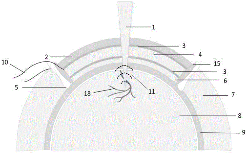
附图序号说明:1为脉冲激光;2为环氧树脂背衬层;3为ITO电极;4为PVDF材料;5为固定结构;6为匹配层;7为皮肤;8为脑部结构;9为颅骨;10为导电银丝;11为光声信号;12为不锈钢治具;13为PVDF-ITO压电薄膜;14为第一信号线;15为连接环;16为透明弧形换能器;17为表皮组织;18为脑部血管;19为第二信号线;20为透明换能器颅窗;21为扫描透镜;22为532nm激光器;23为1064nm激光器;24为光阑;25为光纤耦合器;26为光纤跳线;27为光纤准直器;28为反射镜;29为二维振镜扫描仪;30为小鼠;31为显示器;32为图形处理器;33为数据采集系统;34为前置放大滤波系统。Description of the serial numbers of the attached drawings: 1 is the pulse laser; 2 is the epoxy resin backing layer; 3 is the ITO electrode; 4 is the PVDF material; 5 is the fixed structure; 6 is the matching layer; 7 is the skin; 8 is the brain structure; 9 10 is a conductive silver wire; 11 is a photoacoustic signal; 12 is a stainless steel fixture; 13 is a PVDF-ITO piezoelectric film; 14 is a first signal line; 15 is a connecting ring; 16 is a
具体实施方式Detailed ways
为了使本技术领域的人员更好地理解本申请方案,下面将结合本申请实施例中的附图,对本申请实施例中的技术方案进行清楚、完整地描述。显然,所描述的实施例仅仅是本申请一部分实施例,而不是全部的实施例。基于本申请中的实施例,本领域技术人员在没有做出创造性劳动前提下所获得的所有其他实施例,都属于本申请保护的范围。In order to enable those skilled in the art to better understand the solutions of the present application, the technical solutions in the embodiments of the present application will be clearly and completely described below in conjunction with the drawings in the embodiments of the present application. Apparently, the described embodiments are only some of the embodiments of this application, not all of them. Based on the embodiments in this application, all other embodiments obtained by those skilled in the art without making creative efforts belong to the scope of protection of this application.
实施例Example
如图1所示,本实施公开了一种基于PVDF-ITO透明换能器颅窗的光声脑成像系统,包括弧形透明换能器、透明换能器颅窗和光声脑成像单元,所述弧形透明换能器与透明换能器颅窗连接,脉冲激光1经过透明换能器颅窗后在光声脑成像单元中成像。As shown in Figure 1, this implementation discloses a photoacoustic brain imaging system based on a PVDF-ITO transparent transducer cranial window, including an arc-shaped transparent transducer, a transparent transducer cranial window and a photoacoustic brain imaging unit. The arc-shaped transparent transducer is connected with the cranial window of the transparent transducer, and the
进一步的,所述弧形透明换能器16由ITO电极3(透明锡-铟氧化物)、PVDF压电材料4(聚偏氟乙烯)、导电银丝10、环氧树脂背衬层2以及匹配层6制备而成,并根据颅骨9的弧形结构进行设计。Further, the curved
可以理解的是,ITO是一种常用的透明电极材料,在450nm-1100nm范围内透光率大于60%,远高于许多其它透明导体。It can be understood that ITO is a commonly used transparent electrode material, and its light transmittance is greater than 60% in the range of 450nm-1100nm, which is much higher than that of many other transparent conductors.
PVDF压电材料具有宽带宽、低声阻抗、高接收灵敏度特性,非常适合用来接收光声成像中的宽频谱光声信号,而且PVDF的机械柔韧性允许根据研究需求自定义形状。在光学性能方面,PVDF在可见光和近红外波段范围内具有高透光率(>80%)。因此,结合PVDF-ITO材料的优势有望研发用于光声成像的高性能的透明超声换能器。PVDF piezoelectric material has the characteristics of wide bandwidth, low acoustic impedance, and high receiving sensitivity, which is very suitable for receiving wide-spectrum photoacoustic signals in photoacoustic imaging, and the mechanical flexibility of PVDF allows custom shapes according to research needs. In terms of optical properties, PVDF has high light transmittance (>80%) in the visible and near-infrared range. Therefore, combining the advantages of PVDF-ITO materials is expected to develop high-performance transparent ultrasonic transducers for photoacoustic imaging.
如图2(a)-图2(c)所示,所述弧形透明换能器的制备过程如下:As shown in Figure 2(a)-Figure 2(c), the preparation process of the curved transparent transducer is as follows:
(1)根据脑成像中声学参数的需求,使用COMSOL仿真软件和基于MATLAB中的FieldⅡ工具包对PVDF-ITO压电薄膜性能进行仿真分析,获取压电材料声学、光学及电阻抗的参数最优解;(1) According to the requirements of acoustic parameters in brain imaging, use COMSOL simulation software and the FieldⅡ toolkit based on MATLAB to simulate and analyze the performance of PVDF-ITO piezoelectric film, and obtain the optimal parameters of piezoelectric material acoustics, optics and electrical impedance untie;
(2)使用SolidWorks设计匹配小鼠颅骨弧度特征的背衬结构,通过3D打印获取高精度的背衬模型,使用背衬模型通过翻模的方法获取环氧树脂背衬层2;(2) Use SolidWorks to design a backing structure that matches the radian characteristics of the mouse skull, obtain a high-precision backing model through 3D printing, and use the backing model to obtain the epoxy
(3)将环氧树脂背衬层上下表面进行抛光处理增加其光学透过率;(3) polishing the upper and lower surfaces of the epoxy resin backing layer to increase its optical transmittance;
(4)将带有脱模剂的不锈钢治具12倒置,依次按顺序放置环氧树脂背衬层2、第一导线银丝、设计好的PVDF-ITO压电薄膜、第二导线银丝、匹配层,各个结构层之间涂抹少量的环氧树脂进行固定后由不锈钢治具压紧后放入保温箱中固化。(4) Invert the
进一步的,所述PVDF-ITO压电薄膜为ITO-PVDF-ITO的夹层薄膜结构,所述PVDF-ITO压电薄膜设计厚度为10μm-50μm;所述PVDF-ITO压电薄膜抵抗形变能力强,杨氏模量高于2.5GPa;所述PVDF-ITO压电薄膜介电常数为10-50。Further, the PVDF-ITO piezoelectric film is a sandwich film structure of ITO-PVDF-ITO, and the design thickness of the PVDF-ITO piezoelectric film is 10 μm-50 μm; the PVDF-ITO piezoelectric film has strong resistance to deformation, The Young's modulus is higher than 2.5GPa; the dielectric constant of the PVDF-ITO piezoelectric film is 10-50.
在本申请的一个实施例中,所述透明换能器颅窗20通过连接环15将弧形透明换能器与头皮组织密封结合,保证手术部位的生理状态稳定性且颅窗制备过程中不损伤颅骨结构,换能器颅窗提供光学透明成像窗口20的同时用于接收光声信号,光声信号通过第一信号线14和第二信号线19进行传输。In one embodiment of the present application, the
更进一步的,通过外科手术的方法建立换能器颅窗,具体预期效果如图3所示,具体建立模型如图4所示。Furthermore, the cranial window of the transducer is established by surgical operation, the specific expected effect is shown in Figure 3, and the specific establishment model is shown in Figure 4.
所述透明换能器颅窗的制备过程如下:The preparation process of the transparent transducer cranial window is as follows:
(1)首先根据目标成像区域对表皮组织17进行脱毛处理,使用手术剪刀将脑部结构8中颅骨9上方的头皮移除,颅骨上方暴露位置的形状大小与设计的弧形透明换能器匹配;本实施例以小鼠30为例进行阐述。(1) First, the
(2)对皮肤7进行止血消炎清理,颅骨上方涂抹生理盐水保持颅骨湿润性,使用固定结构将设计好的透明换能器与手术切除的皮肤边缘进行快速止血粘合,保持内环境稳态;常用的固定结构为牙科水泥和α-氰基丙烯酸酯;(3)使用灌封胶将固化成型的弧形透明换能器固定到连接环中;(2) Hemostatic and anti-inflammatory cleaning was performed on the
(4)使用牙科水泥或骨水泥将透明换能器连接环部位与周边皮肤进行固定连接,通过高频同轴屏蔽线与导线银丝相连将PVDF-ITO产生的压电信号导出。(4) Use dental cement or bone cement to fix the connection ring of the transparent transducer with the surrounding skin, and connect the high-frequency coaxial shielded wire with the wire silver wire to export the piezoelectric signal generated by PVDF-ITO.
在本申请的一个实施例中,集成可见光/近红外光的深层成像和基于受激拉曼散射效应的功能成像的成像系统如图5所示;基于快速振镜扫描的高分辨、大深度光声脑结构和功能成像系统中的原理为:In one embodiment of the present application, an imaging system integrating deep imaging of visible light/near-infrared light and functional imaging based on stimulated Raman scattering effect is shown in Figure 5; high-resolution, large-depth light based on fast galvanometer scanning The principle in the acoustic brain structure and function imaging system is:
532nm和1064nm波长的激光器作为光声成像激发源,使用二向色镜合束得到532nm/1064nm波长交替激发的光源。通过532nm激发来获取脑皮层的血管信息,通过近红外光的激发来获取脑深层的血管信息,通过波长互补实现脑部血管的高分辨、大深度成像。Lasers with wavelengths of 532nm and 1064nm are used as excitation sources for photoacoustic imaging, and a dichroic mirror is used to combine beams to obtain a light source with alternate excitation at 532nm/1064nm wavelengths. The vascular information of the cerebral cortex is obtained through 532nm excitation, the blood vessel information of the deep brain is obtained through the excitation of near-infrared light, and the high-resolution and large-depth imaging of brain blood vessels is realized through wavelength complementarity.
进一步的,所述光声脑成像单元包括光学激发扫描模块和信号处理重建模块;其中光学激发扫描模块包括532nm激光器22、1064nm激光器23、光阑24、光纤耦合器25、光纤跳线26、光纤准直器27、反射镜28、二维振镜扫描仪29和扫描透镜21;所述光学激发扫描模块包括两个光路,第一光路包括:顺序连接的532nm激光器、第一光阑、第一光纤耦合器、第一光纤跳线、第一光纤准直器、第一反射镜;第二个光路包括:顺序连接的1064nm激光器、第二光阑、第二光纤耦合器、第二光纤跳线、第二光纤准直器、第二反射镜;所述第一反射镜和第二反射镜连接后与二维振镜扫描仪连接,所述二维振镜扫描仪与扫描透镜连接;所述信号处理重建模块包括顺序连接的前置放大滤波系统、数据采集系统、图像处理器和显示器;信号处理重建模块将透明换能器颅窗接收到的光声信号11还原成光声脑图像,经过放大滤波之后重建出高分辨的三维光声脑图像;所述信号处理重建模块包括顺序连接的前置放大滤波系统34、数据采集系统33、图像处理器32和显示器31;信号处理重建模块将透明换能器颅窗接收到的光声信号还原成光声脑图像,经过放大滤波之后重建出高分辨的三维光声脑图像。Further, the photoacoustic brain imaging unit includes an optical excitation scanning module and a signal processing reconstruction module; wherein the optical excitation scanning module includes a
在本申请的另一个实施例中,基于PVDF-ITO透明换能器颅窗的光声脑成像系统的成像方法,包括下述步骤:In another embodiment of the present application, the imaging method of the photoacoustic brain imaging system based on the PVDF-ITO transparent transducer cranial window comprises the following steps:
FPGA时序控制系统实现对近红外光和可见光的激光激发、控制振镜扫描系统利用连续锯齿波驱动进行连续扫描。The FPGA timing control system realizes the laser excitation of near-infrared light and visible light, and controls the galvanometer scanning system to perform continuous scanning with continuous sawtooth wave drive.
通过光电二极管实现对激发光脉冲能量的监测对功能成像进行校正补偿。The energy of the excitation light pulse is monitored by the photodiode, and the functional imaging is corrected and compensated.
通过LabVIEW软件编写扫描控制、数据采集和成像程序。Programs for scanning control, data acquisition and imaging were written through LabVIEW software.
通过GPU加速信号处理、多波长信号重建、图像配准、实时显示。Accelerate signal processing, multi-wavelength signal reconstruction, image registration, and real-time display through GPU.
本实施例中基于PVDF-ITO透明换能器颅窗的光声脑成像方法及其系统所成的像如图6所示,从图6中可以看出,整个脑部血管18网络的分布情况,实现脑皮层和深层脑血管的高分辨深层成像。In this embodiment, the photoacoustic brain imaging method based on the PVDF-ITO transparent transducer cranial window and the image formed by the system thereof are shown in Figure 6, as can be seen from Figure 6, the distribution of the entire
在本发明中,除非另有明确的规定和限定,术语“安装”、“相连”、“连接”、“固定”等术语应做广义理解,例如,可以是固定连接,也可以是可拆卸连接,或成一体;可以是机械连接,也可以是电连接;可以是直接相连,也可以通过中间媒介间接相连,可以是两个元件内部的连通或两个元件的相互作用关系,除非另有明确的限定。对于本领域的普通技术人员而言,可以根据具体情况理解上述术语在本发明中的具体含义。In the present invention, unless otherwise clearly specified and limited, terms such as "installation", "connection", "connection" and "fixation" should be understood in a broad sense, for example, it can be a fixed connection or a detachable connection , or integrated; it may be mechanically connected or electrically connected; it may be directly connected or indirectly connected through an intermediary, and it may be the internal communication of two components or the interaction relationship between two components, unless otherwise specified limit. Those of ordinary skill in the art can understand the specific meanings of the above terms in the present invention according to specific situations.
在本说明书的描述中,参考术语“一个实施例”、“一些实施例”、“示例”、“具体示例”、或“一些示例”等的描述意指结合该实施例或示例描述的具体特征、结构、材料或者特点包含于本发明的至少一个实施例或示例中。在本说明书中,对上述术语的示意性表述不必须针对的是相同的实施例或示例。而且,描述的具体特征、结构、材料或者特点可以在任一个或多个实施例或示例中以合适的方式结合。此外,在不相互矛盾的情况下,本领域的技术人员可以将本说明书中描述的不同实施例或示例以及不同实施例或示例的特征进行结合和组合。In the description of this specification, descriptions referring to the terms "one embodiment", "some embodiments", "example", "specific examples", or "some examples" mean that specific features described in connection with the embodiment or example , structure, material or characteristic is included in at least one embodiment or example of the present invention. In this specification, the schematic representations of the above terms are not necessarily directed to the same embodiment or example. Furthermore, the described specific features, structures, materials or characteristics may be combined in any suitable manner in any one or more embodiments or examples. In addition, those skilled in the art can combine and combine different embodiments or examples and features of different embodiments or examples described in this specification without conflicting with each other.
尽管上面已经示出和描述了本发明的实施例,可以理解的是,上述实施例是示例性的,不能理解为对本发明的限制,本领域的普通技术人员在本发明的范围内可以对上述实施例进行变化、修改、替换和变型。Although the embodiments of the present invention have been shown and described above, it can be understood that the above embodiments are exemplary and should not be construed as limiting the present invention, those skilled in the art can make the above-mentioned The embodiments are subject to changes, modifications, substitutions and variations.
Claims (10)
Priority Applications (1)
| Application Number | Priority Date | Filing Date | Title |
|---|---|---|---|
| CN202310091895.3A CN116269216A (en) | 2023-02-10 | 2023-02-10 | Photoacoustic brain imaging system and method based on PVDF-ITO transparent transducer cranium window |
Applications Claiming Priority (1)
| Application Number | Priority Date | Filing Date | Title |
|---|---|---|---|
| CN202310091895.3A CN116269216A (en) | 2023-02-10 | 2023-02-10 | Photoacoustic brain imaging system and method based on PVDF-ITO transparent transducer cranium window |
Publications (1)
| Publication Number | Publication Date |
|---|---|
| CN116269216A true CN116269216A (en) | 2023-06-23 |
Family
ID=86795075
Family Applications (1)
| Application Number | Title | Priority Date | Filing Date |
|---|---|---|---|
| CN202310091895.3A Pending CN116269216A (en) | 2023-02-10 | 2023-02-10 | Photoacoustic brain imaging system and method based on PVDF-ITO transparent transducer cranium window |
Country Status (1)
| Country | Link |
|---|---|
| CN (1) | CN116269216A (en) |
Cited By (3)
| Publication number | Priority date | Publication date | Assignee | Title |
|---|---|---|---|---|
| CN117017280A (en) * | 2023-07-24 | 2023-11-10 | 西南交通大学 | Wearable flexible near-infrared photoacoustic/ultrasound dual-modal imaging system and method |
| CN119564343A (en) * | 2024-12-03 | 2025-03-07 | 上海交通大学 | Photoacoustic microscopic imaging brain electrode implantation site and method and system for planning path thereof |
| CN119856919A (en) * | 2025-03-25 | 2025-04-22 | 杭州华驰科技有限公司 | Sitting posture detection system and method |
-
2023
- 2023-02-10 CN CN202310091895.3A patent/CN116269216A/en active Pending
Cited By (4)
| Publication number | Priority date | Publication date | Assignee | Title |
|---|---|---|---|---|
| CN117017280A (en) * | 2023-07-24 | 2023-11-10 | 西南交通大学 | Wearable flexible near-infrared photoacoustic/ultrasound dual-modal imaging system and method |
| CN117017280B (en) * | 2023-07-24 | 2024-03-19 | 西南交通大学 | Wearable flexible near-infrared photoacoustic/ultrasonic dual-mode imaging system and method |
| CN119564343A (en) * | 2024-12-03 | 2025-03-07 | 上海交通大学 | Photoacoustic microscopic imaging brain electrode implantation site and method and system for planning path thereof |
| CN119856919A (en) * | 2025-03-25 | 2025-04-22 | 杭州华驰科技有限公司 | Sitting posture detection system and method |
Similar Documents
| Publication | Publication Date | Title |
|---|---|---|
| CN116269216A (en) | Photoacoustic brain imaging system and method based on PVDF-ITO transparent transducer cranium window | |
| JP6732830B2 (en) | Dual modality image processing system for simultaneous functional and anatomical display mapping | |
| KR102144551B1 (en) | Laser optoacoustic ultrasonic imaging system (louis) and methods of use | |
| US11323625B2 (en) | Subject information obtaining apparatus, display method, program, and processing apparatus | |
| US10709419B2 (en) | Dual modality imaging system for coregistered functional and anatomical mapping | |
| CN102822661B (en) | Photoacoustic imaging device and photoacoustic imaging method | |
| CN100512760C (en) | Method and apparatus for forming an image that shows information about a subject | |
| JP5643101B2 (en) | Scattering medium imaging method, imaging apparatus, and imaging system | |
| US20130301380A1 (en) | Method for dual modality optoacoustic imaging | |
| CN105595964B (en) | Double focusing ultrasonic probe and thinned array Photoacoustic tomography system | |
| CN102871645A (en) | Near-infrared imaging ultrasonic vascular therapeutic apparatus | |
| Zhang et al. | Ultrafast longitudinal imaging of haemodynamics via single-shot volumetric photoacoustic tomography with a single-element detector | |
| WO2024151876A1 (en) | Single-shot 3d imaging using a single detector | |
| JP2015123224A (en) | Photoacoustic apparatus, signal processing method, and program | |
| CN113640392B (en) | High-sensitivity full-transparent photoacoustic detector based on transparent flexible composite electrode and endoscopic device | |
| CN118806238A (en) | A handheld photoacoustic imaging probe and a photoacoustic imaging system | |
| Yang et al. | Photoacoustic imaging of biological tissues based on annular transducer array | |
| US20140066744A1 (en) | Object information acquiring apparatus | |
| SungHun et al. | Optically transparent ultrasound transducers for combined ultrasound and photoacoustic imaging: A review | |
| US10551355B2 (en) | Probe and subject information obtaining apparatus using the same | |
| EP2773267B1 (en) | Dual modality imaging system for coregistered functional and anatomical mapping | |
| Qin et al. | A multi-bandwidth photoacoustic tomography imaging system suitable for small animals | |
| Osman | Development of Transparent Ultrasonic Transducers for Biomedical Applications | |
| Shcherbinin et al. | Theoretical Modeling and Experimental Study of High Intensity Focused Ultrasound Transducers | |
| JP2019005560A (en) | Information processing apparatus and system |
Legal Events
| Date | Code | Title | Description |
|---|---|---|---|
| PB01 | Publication | ||
| PB01 | Publication | ||
| SE01 | Entry into force of request for substantive examination | ||
| SE01 | Entry into force of request for substantive examination |