CN116259908A - A battery pack magnetic fixation structure and method for high-speed water surface vehicles - Google Patents
A battery pack magnetic fixation structure and method for high-speed water surface vehicles Download PDFInfo
- Publication number
- CN116259908A CN116259908A CN202310109459.4A CN202310109459A CN116259908A CN 116259908 A CN116259908 A CN 116259908A CN 202310109459 A CN202310109459 A CN 202310109459A CN 116259908 A CN116259908 A CN 116259908A
- Authority
- CN
- China
- Prior art keywords
- battery pack
- magnetic
- magnet
- piece
- battery
- Prior art date
- Legal status (The legal status is an assumption and is not a legal conclusion. Google has not performed a legal analysis and makes no representation as to the accuracy of the status listed.)
- Pending
Links
Images


Classifications
-
- H—ELECTRICITY
- H01—ELECTRIC ELEMENTS
- H01M—PROCESSES OR MEANS, e.g. BATTERIES, FOR THE DIRECT CONVERSION OF CHEMICAL ENERGY INTO ELECTRICAL ENERGY
- H01M50/00—Constructional details or processes of manufacture of the non-active parts of electrochemical cells other than fuel cells, e.g. hybrid cells
- H01M50/20—Mountings; Secondary casings or frames; Racks, modules or packs; Suspension devices; Shock absorbers; Transport or carrying devices; Holders
- H01M50/244—Secondary casings; Racks; Suspension devices; Carrying devices; Holders characterised by their mounting method
-
- H—ELECTRICITY
- H01—ELECTRIC ELEMENTS
- H01M—PROCESSES OR MEANS, e.g. BATTERIES, FOR THE DIRECT CONVERSION OF CHEMICAL ENERGY INTO ELECTRICAL ENERGY
- H01M50/00—Constructional details or processes of manufacture of the non-active parts of electrochemical cells other than fuel cells, e.g. hybrid cells
- H01M50/20—Mountings; Secondary casings or frames; Racks, modules or packs; Suspension devices; Shock absorbers; Transport or carrying devices; Holders
- H01M50/289—Mountings; Secondary casings or frames; Racks, modules or packs; Suspension devices; Shock absorbers; Transport or carrying devices; Holders characterised by spacing elements or positioning means within frames, racks or packs
- H01M50/293—Mountings; Secondary casings or frames; Racks, modules or packs; Suspension devices; Shock absorbers; Transport or carrying devices; Holders characterised by spacing elements or positioning means within frames, racks or packs characterised by the material
Landscapes
- Chemical & Material Sciences (AREA)
- Chemical Kinetics & Catalysis (AREA)
- Electrochemistry (AREA)
- General Chemical & Material Sciences (AREA)
- Battery Mounting, Suspending (AREA)
Abstract
The invention discloses a magnetic fixing structure and a magnetic fixing method for a battery pack of a high-speed water surface aircraft, wherein the battery pack is positioned in a battery compartment of the high-speed water surface aircraft, a magnetic fixing piece is embedded in the battery compartment of the high-speed water surface aircraft, and a magnetic moving piece is arranged corresponding to the fixing piece and is arranged on the battery pack; and the fixing piece and the corresponding moving piece generate mutual attractive force, so that the battery pack is fixed in the battery compartment. The invention also provides a magnetic fixing method for the battery pack, which is applied to the structure, and the magnetic fixing structure and the method provided by the invention are characterized in that the battery pack can be fixed on the battery compartment of the plate body without direct contact according to the attractive force action of magnetic force by arranging the magnetic fixing piece and the magnetic moving piece respectively in the battery compartment and outside the battery pack, so that the problem of difficult maintenance and the like caused by the need of carrying out opening treatment on the surface of the plate body in the mechanical fixing method of the battery pack in the prior art is solved.
Description
Technical Field
The invention relates to the technical field of high-speed water surface aircrafts, in particular to a battery pack magnetic force fixing structure and method for a high-speed water surface aircrafts.
Background
The high-speed water surface aircraft comprises a plate body, a propeller, a battery pack and the like, wherein the battery pack supplies power for the propeller, provides energy for the operation of the propeller, the propeller sucks seawater, the propeller ejects water through high-speed operation, and the water surface aircraft is pushed to advance at high speed according to the interaction principle of force.
The battery pack is installed in the battery compartment of the plate body, and the battery pack needs to be frequently taken out from the battery compartment of the plate body of the high-speed surface vehicle in order to facilitate charging, maintenance and maintenance of the battery pack. Therefore, in designing the structure of the high-speed surface vehicle, it is necessary to design the fixing and attaching/detaching structure of the battery pack.
Conventionally, the fixing and dismounting of the battery pack and the high-speed surface vehicle board body generally adopt a mechanical method, and are specifically divided into a threaded type and a buckle type. (1) The screw thread method is to pre-embed the internal screw thread (external screw thread) into the plate battery compartment, expose the screw thread connection part to the plate battery compartment, then put the battery pack into the plate battery compartment, then assemble the corresponding external screw thread (internal screw thread) on the battery pack with the screw thread on the plate battery compartment, and fix the battery pack after screwing. When the battery pack is taken down, the battery pack can be taken down only by unscrewing the screw thread. (2) The snap-in method is similar to the screw-type by attaching a portion of the snap-in connector to each of the plate battery compartment and the battery pack. When the battery pack is installed, the buckle is locked, and when the battery pack is taken down, the buckle is loosened. The buckle also needs to be implanted into the battery compartment of the plate body in advance in a pre-buried mode.
In the traditional two mounting modes, one half of the screw thread (internal screw thread or external screw thread) or one half of the buckle (buckle column or buckle seat) is required to be placed inside the plate body of the high-speed water surface aircraft in an embedded part mode, and meanwhile, after the composite material on the surface of the plate body is required to be cut, the other half of the screw thread or the other half of the buckle is exposed outside the plate body.
Therefore, in the conventional mechanical fixing method of the battery pack, the mechanical connection assembly (such as a half of a thread or a half of a buckle) needs to be pre-buried, and the composite material on the surface of the plate body is subjected to opening treatment, so that the mechanical connection assembly is difficult to replace and maintain after failure, and in addition, if the surface of the plate body is provided with a notch, the plate body is easy to fail from the notch.
Disclosure of Invention
The invention aims to provide a magnetic fixing structure and a magnetic fixing method for a battery pack of a high-speed water surface aircraft, which are used for solving the problems of difficult maintenance and the like caused by the need of carrying out opening treatment on the surface of a plate in a mechanical fixing method for the battery pack in the prior art.
In a first aspect of the present invention, there is provided a battery pack magnetic force securing structure for a high speed surface vehicle,
the battery pack is positioned in a battery compartment of the high-speed water surface aircraft, a magnetic fixing piece is embedded in the battery compartment of the high-speed water surface aircraft, and a magnetic moving piece is arranged corresponding to the fixing piece and is arranged on the battery pack;
and the fixing piece and the corresponding moving piece generate mutual attractive force, so that the battery pack is fixed in the battery compartment.
Further, the fixing piece and the corresponding moving piece adopt different magnet structures;
when the fixed piece adopts a permanent magnet, the moving piece is embedded with a magnetizer; when the fixing piece adopts a magnetizer, the moving piece is embedded with a permanent magnet.
Further, the battery pack is a straight parallelepiped with an upper side turned over, the battery pack is installed in a battery compartment of the high-speed water surface aircraft, and the upper side turned over of the battery pack is arranged at a continuous edge of the upper edge of the battery compartment;
a plurality of magnetic fixing pieces are embedded in the continuous edge of the upper edge of the battery compartment, each fixing piece is correspondingly provided with one moving piece which is arranged on the cover of the battery pack, and the battery pack is fixed in the battery compartment of the plate body through mutual attractive force between the moving piece and the fixing piece.
Further, a movable magnet is arranged in the moving member, the moving direction of the magnet is perpendicular to the magnetic force direction between the moving member and the fixed member, and the mutual attractive force between the moving member and the corresponding fixed member can be adjusted by adjusting the movement of the magnet in the direction perpendicular to the magnetic force direction.
Further, the moving part further comprises a surrounding frame, a cavity is formed in the side wall of the surrounding frame, a buckling mechanism is installed in the cavity and consists of an elastic arm and protruding points, and the magnet moves in the surrounding frame by pushing the buckling mechanism.
Further, the surrounding frame is fixed on the flanging, and is glued on the cover of the battery pack through the flanging.
Further, the upper surface of the magnet is a manual pushing surface and is a slope surface so as to facilitate lateral pushing.
In a second aspect of the invention, there is provided a battery pack magnetic force securing method for a high speed surface craft, the method comprising:
the battery compartment of the plate body is internally provided with a magnetic fixing piece, the battery pack is provided with a magnetic moving piece at a position corresponding to the fixing piece, and the moving piece and the fixing piece form a magnetic pair;
the number of the magnetic pairs is determined according to the safety coefficient requirements by combining the weight of the battery compartment, so that the battery pack is fixed in the plate battery compartment by means of magnetic force.
Further, by adjusting the position of the magnet inside the moving member, the magnet inside the moving member and the magnet inside the fixed member are staggered to unlock the battery pack, or the magnet inside the moving member and the magnet inside the fixed member are moved to the same vertical plane to lock the battery pack.
Further, the number of magnetic pairs and the gap distance between the moving part and the fixed part are determined according to the magnetic field intensity between the moving part and the fixed part, the weight of the battery compartment, the storm level and the safety coefficient in the sailing process;
preferably 4 magnetic pairs, the gap distance is not more than 9mm.
Compared with the prior art, the invention has the following beneficial effects:
according to the magnetic force fixing structure and the magnetic force fixing method, the fixing piece and the moving piece which are magnetic are respectively arranged in the battery compartment and outside the battery pack, and the moving piece and the fixing piece can fix the battery pack on the battery compartment of the plate body without direct contact according to the attractive force action of the magnetic force. On the one hand, embedded parts in the plate body, namely the fixing parts, are installed in an embedded mode without exposing the surface of the plate body, so that the failure probability of the embedded parts is reduced, and the service life of the embedded parts is prolonged. On the other hand, the composite material (namely the plate body skin) on the surface of the plate body is not required to be notched, and as the skin is not provided with openings, the local stress concentration of the skin is reduced, and the strength of the skin is improved.
Drawings
In order to more clearly illustrate the embodiments of the present invention or the technical solutions in the prior art, the drawings used in the description of the embodiments or the prior art will be briefly described below. It will be apparent to those skilled in the art from this disclosure that the drawings described below are merely exemplary and that other embodiments may be derived from the drawings provided without undue effort.
FIG. 1 is a schematic view of a high-speed surface vehicle according to an embodiment of the present invention;
fig. 2 is a schematic structural view of a battery pack according to an embodiment of the present invention;
FIG. 3 is a schematic view of a battery compartment according to an embodiment of the present invention;
FIG. 4 is a schematic view illustrating the installation of a moving member according to an embodiment of the present invention;
FIG. 5 is a schematic diagram of the moving member and the fixed member according to the embodiment of the present invention;
FIG. 6 is a schematic diagram of geometric parameters of a permanent magnet according to an embodiment of the present invention;
FIG. 7 is a schematic diagram showing a locked state of the magnetic fixing structure according to an embodiment of the present invention;
FIG. 8 is a schematic diagram illustrating an unlocked state of a magnetic fixing structure according to an embodiment of the present invention;
FIG. 9 is a schematic diagram of a moving member according to an embodiment of the present invention;
reference numerals in the drawings:
the high-speed water surface craft comprises a 1-high-speed water surface craft body, a 2-plate body, a 3-battery pack, a 4-front hydrofoil, a 5-rear hydrofoil, a 6-propeller, a 7-battery compartment, continuous edges of upper edges of 8-1, 8-2 and 8-3 battery compartments, notched edges at bottoms of 9-1 and 9-2 battery compartments, a 10-battery pack shell, a 11-cover, 12-1, 12-2, 12-3 and 12-4 moving parts, 13-fixing parts, 14-buckles, 15-elastic arms, 16-surrounding frames, 17-flanges, 18-magnets and 19-salient points.
Detailed Description
The following description of the embodiments of the present invention will be made clearly and completely with reference to the accompanying drawings, in which it is apparent that the embodiments described are only some embodiments of the present invention, but not all embodiments. All other embodiments, which can be made by those skilled in the art based on the embodiments of the invention without making any inventive effort, are intended to be within the scope of the invention.
The utility model provides a high-speed surface of water aircraft 1, as shown in fig. 1, including plate body 2, battery package 3, preceding hydrofoil 4, back hydrofoil 5 and propeller 6, battery package 3 is installed in the battery compartment 7 of plate body 2, and propeller 6 is installed in the propeller 6 cabin of plate body 2, and battery package 3 provides power for the operation of propeller 6, and under the circumstances of battery package 3 power supply, the high-speed rotation of utilization propeller 6 is spouted the rivers, promotes the surface of water aircraft forward through the reaction force of rivers blowout.
As shown in fig. 2, the battery pack 3 is composed of a casing 10 and a cover 11 of the battery pack, a concave-convex ordered groove structure is designed at the bottom of the plate battery compartment 7, the bottom surface of the battery compartment 7 is composed of three continuous edges and two notched edges 9-1 and 9-2, and the upper edge of the battery compartment 7 is composed of three continuous edges 8-1, 8-2 and 8-3, as shown in fig. 3, the battery pack 3 is positioned in the battery compartment 7.
To facilitate charging, maintenance, and servicing of the battery pack 3, the battery pack 3 needs to be removed from the panel battery compartment 7 of the high-speed surface vehicle 1 from time to time. Therefore, the invention provides a battery pack magnetic force fixing structure for a high-speed water surface aircraft, which comprises the following specific structures:
the battery pack 3 is positioned in the battery compartment 7 of the high-speed water surface aircraft, the battery compartment 7 of the high-speed water surface aircraft 1 is embedded with a magnetic fixing piece 13, and a moving piece 12 with magnetism is arranged on the battery pack 3 corresponding to the fixing piece 13, as shown in fig. 4; the fixing members 13 and the corresponding moving members 12 generate attractive force therebetween so that the battery pack 3 is fixed in the battery compartment 7.
The invention fixes the battery pack 3 by arranging a moving part 12 and a fixing part 13 which are mutually matched in the vertical direction on the battery compartment 7 of the plate body 2 and the battery pack 3; thus, the fixing part 13 is used as an embedded part inside the plate body and does not need to be exposed outside the plate body, so that the failure probability of the embedded part is reduced, and the service life of the embedded part is prolonged. On the other hand, the composite material on the surface of the plate body does not need to be notched, and as the skin is not provided with openings, the local stress concentration of the skin is reduced, and the strength of the skin is improved.
In order to ensure the magnetic force intensity between the moving part 12 and the fixed part 13, the fixed part 13 and the corresponding moving part 12 adopt different magnet structures; when the fixed piece 13 adopts a permanent magnet, the moving piece 12 is embedded with a magnetizer; when the fixed member 13 adopts a magnetizer, the movable member 12 is embedded with a permanent magnet. The moving part and the fixed part select different magnet types, so that the problem of consistency of magnetic field directions is not needed to be considered, and the selection and the arrangement of the magnet types are simplified. The permanent magnet is a strong permanent magnet made of neodymium iron boron material, and the magnetizer is a steel material.
The working principle of the magnetic force fixing structure is as follows: the magnetic force generated by the magnetic force pair formed by the moving part 12 and the fixing part 13 is finally transmitted to the battery compartment 7 of the plate body 2 and the battery pack 3, so that the mutual attraction acting force between the plate body 2 and the battery pack 3 is formed, and the fixation of the battery pack 3 and the plate body 2 is realized.
In general, geometric parameters of the magnet structure are determined according to the weight of the battery pack 3, and accurate magnetic force pair design optimization can be obtained through electromagnetic simulation and actual experimental measurement.
It is known that: the total weight of the battery pack 3 is m=18 kg, and assuming that the safety factor of the magnetic force required to fix the battery pack 3 is rf=2.0: the magnetic force fixing structure needs to provide fixing force as follows:
F=mg·RF=18kg·10m/s 2 ·2.0=360N
wherein g is the gravitational acceleration, 10m/s 2 。
The magnet structures of the magnetic force pair are permanent magnets and magnetizers, one magnet structure can be selected from the moving member 12 and the fixed member 13, as shown in fig. 5, the moving member 12 and the fixed member 13 are different magnet structures, the geometric parameters are the same, and a gap is reserved between the two magnet structures. The geometric parameters of the permanent magnet are shown in fig. 6, the length is denoted as L, the width is denoted as W, the height (thickness) is denoted as H, the gap from the magnetizer is denoted as x, and the geometrical parameters of the magnetizer and the permanent magnet are the same.
The gap x between the moving part and the fixed part is the vertical distance between the moving part and the fixed part, the smaller the distance is, the stronger the magnetic field is, and the size of the magnetic field force between the moving part and the fixed part can be determined by determining the gap distance because the fixed part is embedded in the battery compartment and a plate body structure is arranged between the moving part and the fixed part.
In this embodiment, the distance between the magnet structures is the thickness of the plate body 2 and the battery pack 3 between the moving member 12 and the fixed member 13 in the actual mounting process.
35# neodymium iron boron is selected as a permanent magnet, the length is selected to be L=50 mm, the width is selected to be W=20 mm, the height is selected to be H=20 mm, and the gap x=6 mm between the permanent magnet and the magnetizer is considered.
Let the coercivity br=1.4 Tesla of the magnet.
Then, the magnetic field forces of the permanent magnet and the magnetizerThe formula is Due to mu r >>1->
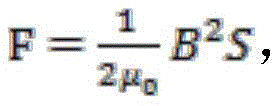 Wherein B is the magnetic field strength at the active surface.
The magnetic field intensity B of x at the center point of the surface of the permanent magnet is as follows:

based on the calculation, a single magnet pair with the geometric parameters and magnetic force characteristics can provide a magnetic force of 116.7N. If 4 permanent magnets are chosen, a magnetic force of 466.8N in the vertical direction can be provided. The safety factor is 466.8/180=2.59 > 2. Therefore, in this embodiment, the battery pack 3 can be fixed by installing 4 neodymium-iron-boron permanent magnets with such design parameters.
Wherein the gap x cannot be too large, the larger the gap, the smaller the magnetic force that the magnet pair can provide. Thus, the first and second substrates are bonded together,
assuming a calm wind condition, the safety factor is 2, and 4 permanent magnets are selected, then the maximum gap is calculated to be 9mm according to the following formula.

Assuming that the wind wave level is three-level, the safety coefficient is 3, and 4 permanent magnets are selected, the gap x under the extremely severe condition can be obtained by calculation according to the above formula and is 1.5mm.
Therefore, the number of magnetic pairs and the gap distance between the moving part and the fixed part can be determined according to the magnetic field intensity between the moving part and the fixed part, the weight of the battery compartment, the wind and wave level and the safety coefficient in the sailing process, and then the installation positions of the moving part and the fixed part are determined.
In a preferred embodiment, 4 sets of magnetic pairs are selected, with a gap distance of no more than 9mm. In this embodiment, only an example of selecting 4 magnetic pairs is given, and the number of other magnetic pairs can be selected according to the estimated weight of the battery pack and the above formula, and is not limited to 4 permanent magnets, and the gap distance is generally not more than 9mm, because in general, the gap distance between the moving member and the fixed member is more than 9mm, and the distance between the moving member and the fixed member is too far and unattractive.
In one embodiment, the battery pack 3 is a straight parallelepiped with an upper flange, as shown in fig. 2, the battery pack 3 is installed in a battery compartment 7 of a high-speed surface vehicle, the upper flange of the battery pack 3 is placed at a continuous edge of the upper edge of the battery compartment 7, and a cover 11 covers the upper surface of the battery pack 3, so that the interior of the battery pack 3 forms a closed space.
A plurality of magnetic fixing members 13 are embedded in the upper edge of the battery compartment 7, each fixing member 13 is correspondingly provided with a moving member 12 which is arranged on the cover 11 of the battery pack 3, and the battery pack 3 is fixed in the battery compartment 7 of the plate body 2 through the mutual attraction between the moving member 12 and the fixing member 13.
In this embodiment, the weight of the battery pack 3 is generally not more than 18kg, and it is generally preferable to install 4 fixing members 13 in the battery compartment 7 of the plate body 2, and the moving member 12 corresponding to each fixing member 13 is installed on the cover 11 of the battery pack 3, as shown in fig. 4. So that the mutual attractive force of the moving member 12 and the fixing member 13 in the vertical direction can fix the battery pack 3 in the battery compartment 7.
In the invention, the movable magnet 18 is arranged in the movable member 12, the movement direction of the magnet 18 is perpendicular to the magnetic force direction between the movable member 12 and the fixed member 13, and the size of the mutual attractive force between the movable member 12 and the corresponding fixed member 13 can be adjusted by adjusting the movement of the magnet 18 in the direction perpendicular to the magnetic force direction.
In the magnetic force fixing structure, a magnetic force pair consisting of a permanent magnet and a magnetizer is a core component of the magnetic force fixing structure. There are two designs of the moving member 12 and the fixed member 13: firstly, the magnet 18 in the moving part 12 is a permanent magnet, and the magnet 18 in the fixed part 13 is a magnetizer; and secondly, the magnet 18 in the fixed part 13 is a permanent magnet, and the magnet 18 in the moving part 12 is a magnetizer. By adjusting the magnet position inside the moving member 12, the magnetic force fixing structure is in a locked state or an unlocked state in cooperation with the magnitude of the mutual attractive force between the magnets 18 inside the fixing member 13.
When in the locked state, the movable member 12 and the fixed member 13 are positioned in a vertical direction, as shown in fig. 7, and the battery pack 3 is fixed in the plate battery compartment 7 without being displaced. As shown in fig. 8, when the battery pack 3 is in the unlocked state, the positions of the moving member 12 and the fixed member 13 are completely staggered, so that the battery pack 3 can be taken out from or put into the plate battery compartment 7, and the battery pack 3 is convenient to charge, repair, maintain and the like.
In a specific embodiment, the moving member 12 is further configured, as shown in fig. 9, where the moving member 12 further includes a surrounding frame 16, a cavity is disposed on a side wall of the surrounding frame 16, a fastening mechanism 14 is installed in the cavity, the fastening mechanism 14 is composed of an elastic arm 15 and a bump 19, and the magnet 18 moves in the surrounding frame 16 by pushing the fastening mechanism 14.
In this embodiment, the enclosure frame 16 is used as a housing of the magnet of the moving member 12, and surrounds the magnet 18 from outside, so as to ensure that the magnet 18 can only move within a set range, and meanwhile, the moving direction of the magnet 18 is perpendicular to the magnetic force direction between the magnet 18 and the fixed member, so that the enclosure frame 16 is made of a non-magnetic material to avoid the influence of the housing on the magnetic force.
In addition, the peripheral frame 16 is fixed on the flange 17, and is glued (may be structural adhesive, pressure sensitive adhesive, hot melt adhesive, silicone adhesive, or the like) to the cover 11 of the battery pack 3 by the flange 17, so that the movable member 12 can be glued and fixed to the battery pack 3 without the operations such as punching. The side wall of the surrounding frame 16 is provided with the buckling mechanism 14, the elastic arm 15 is composed of two arc-shaped elastic rods, the salient point 19 is positioned between the two arc-shaped elastic rods, and the magnet 18 can be pushed to move in the surrounding frame 16 only under the condition that the force is larger than the elastic force of the buckling mechanism 14, so that the magnet 18 in the moving part 12 can be prevented from moving randomly.
Furthermore, in the moving member 12, the upper surface of the magnet 18 is a manual pushing surface, and is a slope surface, so as to facilitate lateral pushing.
It should be noted that, in the present invention, a magnetic force is provided between the fixed member and the moving member, the force of the elastic arm in the unlocking direction is perpendicular to the magnetic force direction, and the motion in the direction perpendicular to the magnetic force direction is less affected by the magnetic force than in the same manner as the unlocking direction and the magnetic force direction, that is, the unlocking is easier, and compared with the common mode of fixing the magnetic buckle on the backpack, the unlocking is easier, in this embodiment, the unlocking force is dependent on the force of the elastic arm, and the relevance between the moving member and the fixed member is small.
The invention also provides a fixing method applied to the battery pack magnetic fixing structure, which comprises the following steps:
the battery compartment of the plate body is internally provided with a magnetic fixing piece, the battery pack is provided with a magnetic moving piece at a position corresponding to the fixing piece, and the moving piece and the fixing piece form a magnetic pair; the number of the magnetic pairs is determined according to the safety coefficient requirements by combining the weight of the battery compartment, so that the battery pack is fixed in the plate battery compartment by means of magnetic force.
In the method, the position of the magnet in the moving part is adjusted, so that the magnet in the moving part and the magnet in the fixed part are staggered to unlock the battery pack, or the magnet in the moving part and the magnet in the fixed part move to the same vertical plane to lock the battery pack.
In the method, the number of magnetic pairs and the gap distance between the moving part and the fixed part are determined according to the magnetic field intensity between the moving part and the fixed part, the weight of the battery compartment, the wind and wave level and the safety coefficient in the sailing process. It is generally preferred to have 4 sets of magnetic pairs and then determine the gap distance between the moving member and the fixed member, which is generally no more than 9mm, and further determine the mounting position of the moving member on the lid of the battery pack, and the fixed member is mounted in the battery compartment of the plate body in a manner that the battery pack is fixed in the battery compartment.
Example 1
In this embodiment, the magnet in the moving part selects the magnetizer, the magnet in the fixed part selects the permanent magnet, the permanent magnet in the plate body is 35# neodymium iron boron, and the magnetizer in the battery pack is made of steel materials.
The dimensions of both are the same, the dimensions of the magnet are as follows: the length is selected to be l=50 mm, the width is selected to be w=20 mm, and the height h=20 mm.
The above embodiments are only exemplary embodiments of the present application and are not intended to limit the present application, the scope of which is defined by the claims. Various modifications and equivalent arrangements may be made to the present application by those skilled in the art, which modifications and equivalents are also considered to be within the scope of the present application.
Claims (10)
1. A battery pack magnetic force fixing structure for a high-speed water surface aircraft is characterized in that,
the battery pack (3) is positioned in the battery compartment (7) of the high-speed water surface aircraft, a magnetic fixing piece (13) is embedded in the battery compartment (7) of the high-speed water surface aircraft, and a magnetic moving piece (12) is arranged corresponding to the fixing piece (13) and is arranged on the battery pack (3);
the fixing piece (13) and the corresponding moving piece (12) generate mutual attractive force, so that the battery pack (3) is fixed in the battery compartment (7).
2. A battery pack magnetic attachment structure for a high speed surface vehicle as defined in claim 1, wherein,
the fixed piece (13) and the corresponding moving piece (12) adopt different magnet structures;
when the fixed piece (13) adopts a permanent magnet, the moving piece (12) is embedded with a magnetizer; when the fixing piece (13) adopts a magnetizer, the moving piece (12) is embedded with a permanent magnet.
3. A battery pack magnetic attachment structure for a high speed surface vehicle as defined in claim 1, wherein,
the battery pack (3) is a straight parallelepiped with a flanging at the upper side, the battery pack (3) is arranged in a battery compartment (7) of the high-speed water surface aircraft, and the upper flanging of the battery pack (3) is arranged at a continuous edge of the upper edge of the battery compartment (7);
a plurality of magnetic fixing pieces (13) are embedded in the continuous edges (8-1, 8-2 and 8-3) of the upper edge of the battery compartment (7), each fixing piece (13) is correspondingly provided with one moving piece (12) which is arranged on the cover (11) of the battery pack, and the battery pack (3) is fixed in the battery compartment (7) of the plate body through the mutual attractive force between the moving piece (12) and the fixing piece (13).
4. A battery pack magnetic force fixation structure for a high speed surface vehicle according to any one of claims 1-3,
the movable part (12) is internally provided with a movable magnet (18), the movement direction of the magnet (18) is perpendicular to the magnetic force direction between the movable part (12) and the fixed part (13), and the size of the mutual attractive force between the movable part (12) and the corresponding fixed part (13) can be adjusted by adjusting the movement of the magnet (18) in the direction perpendicular to the magnetic force direction.
5. A battery pack magnetic force securement structure for a high speed surface vehicle as recited in claim 4, wherein,
the moving part (12) further comprises a surrounding frame (16), a cavity is formed in the side wall of the surrounding frame (16), a buckling mechanism (14) is arranged in the cavity, the buckling mechanism (14) consists of an elastic arm (15) and protruding points (19), and the magnet (18) moves in the surrounding frame (16) through pushing the buckling mechanism (14).
6. A battery pack magnetic force securement structure for a high speed surface vehicle as recited in claim 5, wherein,
the surrounding frame (16) is fixed on the flanging (17), and is glued on the cover (11) of the battery pack through the flanging (17).
7. A battery pack magnetic force securement structure for a high speed surface vehicle as recited in claim 5, wherein,
the upper surface of the magnet (18) is a manual pushing surface and is a slope surface so as to facilitate lateral pushing.
8. A method for magnetically securing a battery pack for a high-speed surface vehicle, the method comprising:
the battery compartment of the plate body is internally provided with a magnetic fixing piece, the battery pack is provided with a magnetic moving piece at a position corresponding to the fixing piece, and the moving piece and the fixing piece form a magnetic pair;
the number of the magnetic pairs is determined according to the safety coefficient requirements by combining the weight of the battery compartment, so that the battery pack is fixed in the plate battery compartment by means of magnetic force.
9. The method for magnetically securing a battery pack for a high-speed surface vehicle as recited in claim 8, wherein,
the position of the magnet in the moving part is adjusted, so that the magnet in the moving part and the magnet in the fixed part are staggered to unlock the battery pack, or the magnet in the moving part and the magnet in the fixed part move to the same vertical plane to lock the battery pack.
10. The method for magnetically securing a battery pack for a high-speed surface vehicle as recited in claim 8, wherein,
determining the number of magnetic pairs and the gap distance between the moving part and the fixed part according to the magnetic field intensity between the moving part and the fixed part, the weight of the battery compartment, the wind and wave level and the safety coefficient in the sailing process;
preferably 4 magnetic pairs, the gap distance is not more than 9mm.
Priority Applications (1)
| Application Number | Priority Date | Filing Date | Title |
|---|---|---|---|
| CN202310109459.4A CN116259908A (en) | 2023-02-14 | 2023-02-14 | A battery pack magnetic fixation structure and method for high-speed water surface vehicles |
Applications Claiming Priority (1)
| Application Number | Priority Date | Filing Date | Title |
|---|---|---|---|
| CN202310109459.4A CN116259908A (en) | 2023-02-14 | 2023-02-14 | A battery pack magnetic fixation structure and method for high-speed water surface vehicles |
Publications (1)
| Publication Number | Publication Date |
|---|---|
| CN116259908A true CN116259908A (en) | 2023-06-13 |
Family
ID=86678819
Family Applications (1)
| Application Number | Title | Priority Date | Filing Date |
|---|---|---|---|
| CN202310109459.4A Pending CN116259908A (en) | 2023-02-14 | 2023-02-14 | A battery pack magnetic fixation structure and method for high-speed water surface vehicles |
Country Status (1)
| Country | Link |
|---|---|
| CN (1) | CN116259908A (en) |
Citations (6)
| Publication number | Priority date | Publication date | Assignee | Title |
|---|---|---|---|---|
| US20040190239A1 (en) * | 2003-03-26 | 2004-09-30 | Shih-Lung Weng | Detachable keyboard structure |
| CN210212690U (en) * | 2019-08-14 | 2020-03-31 | 胡富祥 | Waterproof sealing structure of battery compartment of electric surfboard |
| CN216468174U (en) * | 2021-12-14 | 2022-05-10 | 纽津(威海)电动车有限公司 | Anti-theft electric vehicle battery fixing device |
| EP4035986A1 (en) * | 2021-01-27 | 2022-08-03 | Ewake Germany GmbH | Wake board or surfboard with electrical motor and internal battery |
| CN218085943U (en) * | 2021-08-26 | 2022-12-20 | 浙江风回科技有限公司 | Electric surfboard with battery capable of being quickly assembled |
| CN218448316U (en) * | 2022-04-22 | 2023-02-03 | 永康市鹏城电子科技有限公司 | Large capacity waterproof lithium battery pack |
-
2023
- 2023-02-14 CN CN202310109459.4A patent/CN116259908A/en active Pending
Patent Citations (6)
| Publication number | Priority date | Publication date | Assignee | Title |
|---|---|---|---|---|
| US20040190239A1 (en) * | 2003-03-26 | 2004-09-30 | Shih-Lung Weng | Detachable keyboard structure |
| CN210212690U (en) * | 2019-08-14 | 2020-03-31 | 胡富祥 | Waterproof sealing structure of battery compartment of electric surfboard |
| EP4035986A1 (en) * | 2021-01-27 | 2022-08-03 | Ewake Germany GmbH | Wake board or surfboard with electrical motor and internal battery |
| CN218085943U (en) * | 2021-08-26 | 2022-12-20 | 浙江风回科技有限公司 | Electric surfboard with battery capable of being quickly assembled |
| CN216468174U (en) * | 2021-12-14 | 2022-05-10 | 纽津(威海)电动车有限公司 | Anti-theft electric vehicle battery fixing device |
| CN218448316U (en) * | 2022-04-22 | 2023-02-03 | 永康市鹏城电子科技有限公司 | Large capacity waterproof lithium battery pack |
Similar Documents
| Publication | Publication Date | Title |
|---|---|---|
| CN217281092U (en) | Battery package subassembly reaches electric automobile including it | |
| US9826670B2 (en) | Vehicle | |
| CN104684293B (en) | Electronic installation, shell and coiling tub | |
| CN206493830U (en) | A kind of automobile and its battery tank mounting structure and its Battery case and battery cassette carrier | |
| CN116259908A (en) | A battery pack magnetic fixation structure and method for high-speed water surface vehicles | |
| CN106920713B (en) | The coil rack of A.C. contactor | |
| CN201800516U (en) | Mounting structure of vehicle battery | |
| CN208622825U (en) | A kind of double square electric cell battery modules | |
| CN219163590U (en) | Battery pack frame structure and vehicle | |
| CN217035882U (en) | a battery device | |
| CN220895692U (en) | Battery module curb plate, battery module and vehicle | |
| RU222918U1 (en) | Bracket for attaching attachments, parts and assemblies to the vehicle frame | |
| CN210101300U (en) | Power battery package and vehicle | |
| CN208855444U (en) | A kind of unmanned plane and unmanned plane wireless charging system of wireless charging | |
| CN220963616U (en) | Battery module bracket and battery module without screw locking | |
| CN223427618U (en) | Battery device and electricity utilization device | |
| CN219393443U (en) | Support guide rail assembly and fuel cell packaging structure | |
| CN114590158A (en) | An electric vehicle power battery replacement bracket | |
| CN219476881U (en) | New energy battery insulating side plate | |
| CN206374999U (en) | A kind of tail-rotor main shaft auxiliary positioning target of helicopter | |
| CN209170187U (en) | A kind of shared bicycle vibration generating device based on electromagnetic induction | |
| CN209938497U (en) | Motor controller device of electric automobile | |
| CN206012317U (en) | Battery pack installation structure and battery pack system | |
| EP4545326A1 (en) | A battery module member, a battery module assembly, a battery pack, and a vehicle | |
| CN219226487U (en) | Busbar support and battery module |
Legal Events
| Date | Code | Title | Description |
|---|---|---|---|
| PB01 | Publication | ||
| PB01 | Publication | ||
| SE01 | Entry into force of request for substantive examination | ||
| SE01 | Entry into force of request for substantive examination |