CN116249479A - Metal detection apparatus and method of operating the same - Google Patents
Metal detection apparatus and method of operating the same Download PDFInfo
- Publication number
- CN116249479A CN116249479A CN202180068062.4A CN202180068062A CN116249479A CN 116249479 A CN116249479 A CN 116249479A CN 202180068062 A CN202180068062 A CN 202180068062A CN 116249479 A CN116249479 A CN 116249479A
- Authority
- CN
- China
- Prior art keywords
- magnetometer
- distal
- signal
- proximal
- sensitivity
- Prior art date
- Legal status (The legal status is an assumption and is not a legal conclusion. Google has not performed a legal analysis and makes no representation as to the accuracy of the status listed.)
- Pending
Links
- 238000001514 detection method Methods 0.000 title claims abstract description 293
- 229910052751 metal Inorganic materials 0.000 title claims description 129
- 239000002184 metal Substances 0.000 title claims description 129
- 238000000034 method Methods 0.000 title abstract description 77
- 230000005291 magnetic effect Effects 0.000 claims abstract description 141
- 230000035945 sensitivity Effects 0.000 claims description 241
- 238000012360 testing method Methods 0.000 claims description 202
- 230000033001 locomotion Effects 0.000 claims description 183
- 238000005259 measurement Methods 0.000 claims description 45
- 230000004044 response Effects 0.000 claims description 20
- 239000000696 magnetic material Substances 0.000 claims description 16
- 238000005452 bending Methods 0.000 claims description 14
- 230000005484 gravity Effects 0.000 abstract description 48
- 230000000717 retained effect Effects 0.000 abstract description 6
- 230000005294 ferromagnetic effect Effects 0.000 description 53
- 230000006870 function Effects 0.000 description 38
- ZAGRQXMWMRUYRB-UHFFFAOYSA-N 1,2,4,5-tetrachloro-3-(3,4-dichlorophenyl)benzene Chemical compound C1=C(Cl)C(Cl)=CC=C1C1=C(Cl)C(Cl)=CC(Cl)=C1Cl ZAGRQXMWMRUYRB-UHFFFAOYSA-N 0.000 description 31
- 206010070245 Foreign body Diseases 0.000 description 31
- 230000000903 blocking effect Effects 0.000 description 29
- 230000008859 change Effects 0.000 description 27
- UNPTZXSJGZTGJJ-UHFFFAOYSA-N 1,2,3,5-tetrachloro-4-(3,5-dichlorophenyl)benzene Chemical compound ClC1=CC(Cl)=CC(C=2C(=C(Cl)C(Cl)=CC=2Cl)Cl)=C1 UNPTZXSJGZTGJJ-UHFFFAOYSA-N 0.000 description 22
- 238000000926 separation method Methods 0.000 description 19
- 238000010586 diagram Methods 0.000 description 18
- 239000013598 vector Substances 0.000 description 16
- YAHNWSSFXMVPOU-UHFFFAOYSA-N 2,3',4,4',5'-Pentachlorobiphenyl Chemical compound ClC1=CC(Cl)=CC=C1C1=CC(Cl)=C(Cl)C(Cl)=C1 YAHNWSSFXMVPOU-UHFFFAOYSA-N 0.000 description 15
- 230000000694 effects Effects 0.000 description 14
- 230000008569 process Effects 0.000 description 14
- 229910001220 stainless steel Inorganic materials 0.000 description 12
- 238000001727 in vivo Methods 0.000 description 11
- 239000000463 material Substances 0.000 description 11
- 239000010935 stainless steel Substances 0.000 description 11
- UDMZPLROONOSEF-UHFFFAOYSA-N 1,2,4,5-tetrachloro-3-(2,4,5-trichlorophenyl)benzene Chemical compound C1=C(Cl)C(Cl)=CC(Cl)=C1C1=C(Cl)C(Cl)=CC(Cl)=C1Cl UDMZPLROONOSEF-UHFFFAOYSA-N 0.000 description 10
- 230000002829 reductive effect Effects 0.000 description 10
- 238000004364 calculation method Methods 0.000 description 9
- 238000004891 communication Methods 0.000 description 9
- 230000007423 decrease Effects 0.000 description 9
- 230000007246 mechanism Effects 0.000 description 9
- 230000001133 acceleration Effects 0.000 description 8
- 230000004397 blinking Effects 0.000 description 7
- 238000001914 filtration Methods 0.000 description 7
- RTAQQCXQSZGOHL-UHFFFAOYSA-N Titanium Chemical compound [Ti] RTAQQCXQSZGOHL-UHFFFAOYSA-N 0.000 description 6
- 239000010936 titanium Substances 0.000 description 6
- 229910052719 titanium Inorganic materials 0.000 description 6
- XEEYBQQBJWHFJM-UHFFFAOYSA-N Iron Chemical compound [Fe] XEEYBQQBJWHFJM-UHFFFAOYSA-N 0.000 description 4
- 239000000853 adhesive Substances 0.000 description 4
- 230000001070 adhesive effect Effects 0.000 description 4
- 238000013459 approach Methods 0.000 description 4
- 230000008901 benefit Effects 0.000 description 4
- 230000003247 decreasing effect Effects 0.000 description 4
- 210000000056 organ Anatomy 0.000 description 4
- 239000002861 polymer material Substances 0.000 description 4
- 238000001356 surgical procedure Methods 0.000 description 4
- CWYNVVGOOAEACU-UHFFFAOYSA-N Fe2+ Chemical compound [Fe+2] CWYNVVGOOAEACU-UHFFFAOYSA-N 0.000 description 3
- 208000027418 Wounds and injury Diseases 0.000 description 3
- 229910052782 aluminium Inorganic materials 0.000 description 3
- XAGFODPZIPBFFR-UHFFFAOYSA-N aluminium Chemical compound [Al] XAGFODPZIPBFFR-UHFFFAOYSA-N 0.000 description 3
- 239000003086 colorant Substances 0.000 description 3
- 230000006378 damage Effects 0.000 description 3
- 239000012634 fragment Substances 0.000 description 3
- 239000007943 implant Substances 0.000 description 3
- 230000005426 magnetic field effect Effects 0.000 description 3
- 230000005389 magnetism Effects 0.000 description 3
- 238000004519 manufacturing process Methods 0.000 description 3
- 239000007769 metal material Substances 0.000 description 3
- 150000002739 metals Chemical class 0.000 description 3
- 238000012986 modification Methods 0.000 description 3
- 230000004048 modification Effects 0.000 description 3
- 229910000889 permalloy Inorganic materials 0.000 description 3
- -1 polyethylene terephthalate Polymers 0.000 description 3
- 229920000139 polyethylene terephthalate Polymers 0.000 description 3
- 239000005020 polyethylene terephthalate Substances 0.000 description 3
- 238000005096 rolling process Methods 0.000 description 3
- 229910000838 Al alloy Inorganic materials 0.000 description 2
- 206010002091 Anaesthesia Diseases 0.000 description 2
- PXHVJJICTQNCMI-UHFFFAOYSA-N Nickel Chemical compound [Ni] PXHVJJICTQNCMI-UHFFFAOYSA-N 0.000 description 2
- 239000004696 Poly ether ether ketone Substances 0.000 description 2
- 210000001015 abdomen Anatomy 0.000 description 2
- 229910045601 alloy Inorganic materials 0.000 description 2
- 239000000956 alloy Substances 0.000 description 2
- 230000037005 anaesthesia Effects 0.000 description 2
- 239000000560 biocompatible material Substances 0.000 description 2
- 210000004204 blood vessel Anatomy 0.000 description 2
- 239000002775 capsule Substances 0.000 description 2
- 229910010293 ceramic material Inorganic materials 0.000 description 2
- 239000002131 composite material Substances 0.000 description 2
- 230000036461 convulsion Effects 0.000 description 2
- 230000008878 coupling Effects 0.000 description 2
- 238000010168 coupling process Methods 0.000 description 2
- 238000005859 coupling reaction Methods 0.000 description 2
- 125000004122 cyclic group Chemical group 0.000 description 2
- 230000007123 defense Effects 0.000 description 2
- 230000000994 depressogenic effect Effects 0.000 description 2
- 238000013461 design Methods 0.000 description 2
- 230000009977 dual effect Effects 0.000 description 2
- 238000005516 engineering process Methods 0.000 description 2
- 239000000945 filler Substances 0.000 description 2
- 238000009499 grossing Methods 0.000 description 2
- 229910052742 iron Inorganic materials 0.000 description 2
- 238000013507 mapping Methods 0.000 description 2
- 238000002324 minimally invasive surgery Methods 0.000 description 2
- 230000036961 partial effect Effects 0.000 description 2
- 229920000058 polyacrylate Polymers 0.000 description 2
- 239000004417 polycarbonate Substances 0.000 description 2
- 229920000515 polycarbonate Polymers 0.000 description 2
- 150000003071 polychlorinated biphenyls Chemical class 0.000 description 2
- 229920002530 polyetherether ketone Polymers 0.000 description 2
- 229920001343 polytetrafluoroethylene Polymers 0.000 description 2
- 239000004810 polytetrafluoroethylene Substances 0.000 description 2
- 238000012545 processing Methods 0.000 description 2
- 230000005855 radiation Effects 0.000 description 2
- 239000000523 sample Substances 0.000 description 2
- 239000007787 solid Substances 0.000 description 2
- 235000014347 soups Nutrition 0.000 description 2
- 230000003068 static effect Effects 0.000 description 2
- 229920002725 thermoplastic elastomer Polymers 0.000 description 2
- 229920002799 BoPET Polymers 0.000 description 1
- 208000000094 Chronic Pain Diseases 0.000 description 1
- 229910001030 Iron–nickel alloy Inorganic materials 0.000 description 1
- 229920000106 Liquid crystal polymer Polymers 0.000 description 1
- 239000004977 Liquid-crystal polymers (LCPs) Substances 0.000 description 1
- 206010028347 Muscle twitching Diseases 0.000 description 1
- 239000004677 Nylon Substances 0.000 description 1
- 208000002193 Pain Diseases 0.000 description 1
- 241000405070 Percophidae Species 0.000 description 1
- 229920002614 Polyether block amide Polymers 0.000 description 1
- 241001085205 Prenanthella exigua Species 0.000 description 1
- 238000009825 accumulation Methods 0.000 description 1
- 230000003213 activating effect Effects 0.000 description 1
- 230000002411 adverse Effects 0.000 description 1
- 238000004458 analytical method Methods 0.000 description 1
- 210000003484 anatomy Anatomy 0.000 description 1
- 230000002238 attenuated effect Effects 0.000 description 1
- 230000003190 augmentative effect Effects 0.000 description 1
- 239000011324 bead Substances 0.000 description 1
- 230000005540 biological transmission Effects 0.000 description 1
- 229920001577 copolymer Polymers 0.000 description 1
- 230000001351 cycling effect Effects 0.000 description 1
- 238000013480 data collection Methods 0.000 description 1
- 238000011161 development Methods 0.000 description 1
- 238000003745 diagnosis Methods 0.000 description 1
- 229910001039 duplex stainless steel Inorganic materials 0.000 description 1
- 239000013013 elastic material Substances 0.000 description 1
- 229920001971 elastomer Polymers 0.000 description 1
- 230000005611 electricity Effects 0.000 description 1
- 238000000605 extraction Methods 0.000 description 1
- 239000004744 fabric Substances 0.000 description 1
- 239000003302 ferromagnetic material Substances 0.000 description 1
- 229920005570 flexible polymer Polymers 0.000 description 1
- 239000011888 foil Substances 0.000 description 1
- 238000002513 implantation Methods 0.000 description 1
- 238000011065 in-situ storage Methods 0.000 description 1
- 208000014674 injury Diseases 0.000 description 1
- 238000007689 inspection Methods 0.000 description 1
- 230000010354 integration Effects 0.000 description 1
- 210000000936 intestine Anatomy 0.000 description 1
- 238000011835 investigation Methods 0.000 description 1
- 238000005304 joining Methods 0.000 description 1
- 230000005381 magnetic domain Effects 0.000 description 1
- 230000005415 magnetization Effects 0.000 description 1
- 229910001105 martensitic stainless steel Inorganic materials 0.000 description 1
- 230000013011 mating Effects 0.000 description 1
- 238000001465 metallisation Methods 0.000 description 1
- 239000000203 mixture Substances 0.000 description 1
- 238000012544 monitoring process Methods 0.000 description 1
- 229910052759 nickel Inorganic materials 0.000 description 1
- 229920001778 nylon Polymers 0.000 description 1
- 230000008816 organ damage Effects 0.000 description 1
- 229920001721 polyimide Polymers 0.000 description 1
- 229920000642 polymer Polymers 0.000 description 1
- 238000003825 pressing Methods 0.000 description 1
- 230000002035 prolonged effect Effects 0.000 description 1
- 238000013102 re-test Methods 0.000 description 1
- 238000002432 robotic surgery Methods 0.000 description 1
- 230000011664 signaling Effects 0.000 description 1
- 239000010454 slate Substances 0.000 description 1
- 238000003860 storage Methods 0.000 description 1
- 238000010998 test method Methods 0.000 description 1
- 229920001169 thermoplastic Polymers 0.000 description 1
- 239000004416 thermosoftening plastic Substances 0.000 description 1
- 238000012546 transfer Methods 0.000 description 1
- 230000001052 transient effect Effects 0.000 description 1
- 230000000007 visual effect Effects 0.000 description 1
Images


Classifications
-
- A—HUMAN NECESSITIES
- A61—MEDICAL OR VETERINARY SCIENCE; HYGIENE
- A61B—DIAGNOSIS; SURGERY; IDENTIFICATION
- A61B90/00—Instruments, implements or accessories specially adapted for surgery or diagnosis and not covered by any of the groups A61B1/00 - A61B50/00, e.g. for luxation treatment or for protecting wound edges
- A61B90/90—Identification means for patients or instruments, e.g. tags
- A61B90/98—Identification means for patients or instruments, e.g. tags using electromagnetic means, e.g. transponders
-
- A—HUMAN NECESSITIES
- A61—MEDICAL OR VETERINARY SCIENCE; HYGIENE
- A61B—DIAGNOSIS; SURGERY; IDENTIFICATION
- A61B5/00—Measuring for diagnostic purposes; Identification of persons
- A61B5/06—Devices, other than using radiation, for detecting or locating foreign bodies ; Determining position of diagnostic devices within or on the body of the patient
- A61B5/061—Determining position of a probe within the body employing means separate from the probe, e.g. sensing internal probe position employing impedance electrodes on the surface of the body
- A61B5/062—Determining position of a probe within the body employing means separate from the probe, e.g. sensing internal probe position employing impedance electrodes on the surface of the body using magnetic field
-
- G—PHYSICS
- G01—MEASURING; TESTING
- G01V—GEOPHYSICS; GRAVITATIONAL MEASUREMENTS; DETECTING MASSES OR OBJECTS; TAGS
- G01V3/00—Electric or magnetic prospecting or detecting; Measuring magnetic field characteristics of the earth, e.g. declination, deviation
- G01V3/08—Electric or magnetic prospecting or detecting; Measuring magnetic field characteristics of the earth, e.g. declination, deviation operating with magnetic or electric fields produced or modified by objects or geological structures or by detecting devices
- G01V3/081—Electric or magnetic prospecting or detecting; Measuring magnetic field characteristics of the earth, e.g. declination, deviation operating with magnetic or electric fields produced or modified by objects or geological structures or by detecting devices the magnetic field is produced by the objects or geological structures
Landscapes
- Life Sciences & Earth Sciences (AREA)
- Health & Medical Sciences (AREA)
- Engineering & Computer Science (AREA)
- Physics & Mathematics (AREA)
- Surgery (AREA)
- Public Health (AREA)
- Veterinary Medicine (AREA)
- Biomedical Technology (AREA)
- Heart & Thoracic Surgery (AREA)
- Medical Informatics (AREA)
- Molecular Biology (AREA)
- Pathology (AREA)
- Animal Behavior & Ethology (AREA)
- General Health & Medical Sciences (AREA)
- Remote Sensing (AREA)
- Biophysics (AREA)
- Human Computer Interaction (AREA)
- Electromagnetism (AREA)
- Nuclear Medicine, Radiotherapy & Molecular Imaging (AREA)
- Oral & Maxillofacial Surgery (AREA)
- Environmental & Geological Engineering (AREA)
- Geology (AREA)
- General Life Sciences & Earth Sciences (AREA)
- General Physics & Mathematics (AREA)
- Geophysics (AREA)
- Endoscopes (AREA)
- Geophysics And Detection Of Objects (AREA)
- Magnetic Resonance Imaging Apparatus (AREA)
Abstract
Description
相关申请的交叉引用Cross References to Related Applications
本申请要求2020年8月4日提交的美国临时申请第63/060,900号、以及2020年12月22日提交的美国临时申请第63/129,438号的优先权,其全部公开内容通过引用整体并入本文。This application claims priority to U.S. Provisional Application No. 63/060,900, filed August 4, 2020, and U.S. Provisional Application No. 63/129,438, filed December 22, 2020, the entire disclosures of which are incorporated by reference in their entirety This article.
技术领域technical field
本发明一般涉及基于磁力仪的金属检测领域和一种改进的基于磁力仪的金属检测器,所述金属检测器用于检测患者体内留存的具有磁性特征的手术物品,例如尖锐物或RFID标记的海绵、金属植入物、金属线和其他物体。The present invention relates generally to the field of magnetometer-based metal detection and an improved magnetometer-based metal detector for detecting surgical items with magnetic characteristics, such as sharps or RFID-tagged sponges, retained in a patient's body , metal implants, wires and other objects.
背景技术Background technique
外科医生和其他手术室(operating room,OR)的专业人员花费大量的时间和资源来定位患者体内遗留的手术物品(retained surgical item,RSI),例如丢失的手术针、手术器械的破碎部分或的其他类型的尖锐物。微创腹腔镜和机器人手术的发展使外科医生更难找到丢失的针、破碎的器械和其他类型的尖锐物和碎片。遗留的物体会对患者造成严重伤害,包括潜在的慢性疼痛或器官损伤。因此,外科医生和其他OR专业人员竭尽全力确保所有的工具和器械都被清点清楚。然而,当处理每次手术平均的300个工具,工作人员多次轮换,以及工具的部分断裂时,寻找RSI已变得更加常见。根据一项研究,63.8%的受访外科医生在过去12个月内经历了微创手术中的丢针事件。此外,89.6%的受访外科医生报告说在他们的职业生涯中发生了1-5次丢针事件。此外,超过13%的事件需要超过30分钟才能定位并找回丢失的针,并且在3%的情况下,外科医生在进行搜索后无法找到这些针。参见Jayadevan,Rajiv et al.“A protocol to recover needles lost during minimallyinvasive surgery.”JSLS:Journal of the Society of Laparoendoscopic Surgeonsvol.18,4(2014)。Surgeons and other operating room (OR) professionals spend considerable time and resources locating retained surgical items (RSI) in patients, such as lost surgical needles, broken parts of surgical instruments, or Other types of sharp objects. The development of minimally invasive laparoscopic and robotic procedures has made it more difficult for surgeons to find lost needles, broken instruments and other types of sharp objects and debris. Leftover objects can cause serious injury to the patient, including potential chronic pain or organ damage. Therefore, surgeons and other OR professionals go to great lengths to ensure that all tools and instruments are accounted for. However, when dealing with an average of 300 tools per surgery, multiple rotations of staff, and partial breakage of tools, looking for RSI has become more common. According to one study, 63.8% of surgeons surveyed experienced a lost needle during minimally invasive surgery in the past 12 months. In addition, 89.6% of surveyed surgeons reported 1-5 lost needle incidents during their careers. Additionally, more than 13% of incidents took more than 30 minutes to locate and retrieve lost needles, and in 3% of cases the surgeon was unable to locate the needles after conducting a search. See Jayadevan, Rajiv et al. "A protocol to recover needles lost during minimally invasive surgery." JSLS: Journal of the Society of Laparoendoscopic Surgeons vol. 18, 4 (2014).
外科医生和其他OR专业人员最初往往依靠视觉搜索任何金属RSI,例如针、尖锐物和破碎的工具。如果没有找到该物品,患者通常会接受X射线扫描和更多的麻醉,因为OR工作人员要花更多的时间进行搜索。这导致患者和工作人员受到更多的辐射,并增加了因麻醉时间延长而产生并发症的风险。当外科医生最终无法定位丢失的针或尖锐物时,需要向患者披露,并且医院和外科医生都面临声誉受损或诉讼的风险。此外,RSI事件是不能报销的(reimbursable),让医院承担任何进一步的手术(procedure)或解决(settlement)的费用。Surgeons and other OR professionals often rely initially on a visual search for any metallic RSI, such as needles, sharps, and broken tools. If the item is not found, the patient typically undergoes an X-ray scan and more anesthesia because the OR staff spends more time searching. This results in more radiation exposure to patients and staff and increases the risk of complications from prolonged anesthesia. When a surgeon ends up being unable to locate a lost needle or sharp, disclosure needs to be made to the patient, and both the hospital and the surgeon risk reputational damage or lawsuits. In addition, RSI events are not reimbursed (reimbursable), leaving the hospital to bear the cost of any further surgery (procedure) or settlement (settlement).
传统的金属检测设备往往缺乏高度精确地确定金属RSI在患者体内的确切位置的能力。此外,此类设备往往不适合体内检测,不便于携带,也不容易旋转,无法在曲折的解剖结构中进行导航。此外,此类传统的金属检测设备不能适当地消除背景磁场干扰的影响,或者只能通过基本的单点测量或减法算法来消除这种干扰,这可能导致检测不准确。Conventional metal detection equipment often lacks the ability to pinpoint the exact location of metal RSI within a patient's body with a high degree of precision. In addition, such devices are often not suitable for in vivo detection, are not portable, and do not easily rotate to navigate tortuous anatomy. In addition, such traditional metal detection equipment cannot properly remove the effect of background magnetic field interference, or can only remove such interference through basic single-point measurement or subtraction algorithms, which may lead to inaccurate detection.
期望有一种便携式设备,可以使外科医生在患者体内轻松移动和旋转该设备。期望这样的设备不会过于复杂,具有成本效益,并且易于制造。It would be desirable to have a portable device that would allow the surgeon to easily move and rotate the device within the patient's body. Such devices are expected to be uncomplicated, cost-effective, and easy to manufacture.
发明内容Contents of the invention
本发明公开了基于磁力仪的金属检测器、金属检测系统及其操作方法,用于检测患者体内的金属物体(例如,RSI、金属植入物、金属线等)。在一个方面,公开了一种金属检测设备,其包括手柄、从手柄延伸出来的杆(shaft)、以及位于杆的远端的远端感应部分(distal sensing portion)。远端感应部分可以包括近端重力梯度仪和远端重力梯度仪,该近端重力梯度仪包括第一近端磁力仪和第二近端磁力仪,该远端重力梯度仪包括第一远端磁力仪和第二远端磁力仪。该金属检测设备可以包括输出组件(output component)和微控制器(microcontroller),该输出组件被配置为生成用户输出,以提醒用户检测到物体,该微控制器包括一个或多个处理器和存储单元。该一个或多个处理器可被编程为执行存储在存储单元中的指令,以便根据由第一近端磁力仪、第二近端磁力仪、第一远端磁力仪和第二远端磁力仪获得的磁场测量值计算出差分信号(differential signal)。该一个或多个处理器可以被编程为执行进一步的指令,以将信号滤波器(signal filter)和导数(derivative)中的至少一者应用于计算得到的差分信号,以获得检测信号。Disclosed are magnetometer-based metal detectors, metal detection systems, and methods of operation thereof for detecting metal objects (eg, RSI, metal implants, wires, etc.) in a patient. In one aspect, a metal detection device is disclosed that includes a handle, a shaft extending from the handle, and a distal sensing portion located at a distal end of the shaft. The distal sensing portion may include a proximal gravity gradiometer comprising a first proximal magnetometer and a distal gravity gradiometer comprising a first distal magnetometer and a second distal magnetometer. The metal detection device may include an output component and a microcontroller configured to generate a user output to alert the user of the detected object, the microcontroller including one or more processors and memory unit. The one or more processors may be programmed to execute instructions stored in the memory unit to perform the operation according to the A differential signal is calculated from the magnetic field measurements obtained. The one or more processors may be programmed to execute further instructions to apply at least one of a signal filter and a derivative to the calculated differential signal to obtain a detection signal.
信号滤波器可以包括高通滤波器和低通滤波器(例如,二阶滤波器或双极点滤波器(two-pole filter))。例如,高通滤波器可以摆脱漂移和偏移,使平均信号回到零。低通滤波器或二阶滤波器(也称为双极点滤波器)可以更积极地切断高频噪音。例如,高通滤波器可以有5.5Hz的截止频率,低通滤波器可以有10Hz的截止频率。这在以下图40中进一步说明。Signal filters may include high-pass filters and low-pass filters (eg, second-order filters or two-pole filters). For example, a high-pass filter can get rid of drift and offset, bringing the average signal back to zero. A low-pass filter or second-order filter (also known as a two-pole filter) cuts high-frequency noise more aggressively. For example, a high pass filter may have a cutoff frequency of 5.5Hz and a lowpass filter may have a cutoff frequency of 10Hz. This is further illustrated in Figure 40 below.
一个或多个处理器可以被编程为执行进一步的指令,以将检测信号与阈值进行比较,并在检测信号超过阈值时指示输出组件生成用户输出。The one or more processors can be programmed to execute further instructions to compare the detection signal to a threshold and instruct the output component to generate a user output when the detection signal exceeds the threshold.
此外,在另一种模式中,阈值可以被移除或设置为低于零,以便使其在给定的水平或给定的时间段或给定的产品中不被使用,使得声音或音调总是打开的,并且音调和/或光的频率和/或强度可以随着信号的增长和收缩而发生改变。这种模式可以允许观察到低于阈值的信号以作出反应。Also, in another mode, the threshold can be removed or set below zero so that it is not used at a given level or for a given period of time or for a given product such that the sound or pitch is always is open, and the frequency and/or intensity of the tone and/or light can change as the signal grows and contracts. This mode may allow subthreshold signals to be observed for response.
第一近端磁力仪、第二近端磁力仪、第一远端磁力仪和第二远端磁力仪可以是两轴磁力仪。第一近端磁力仪、第二近端磁力仪、第一远端磁力仪和第二远端磁力仪可以各自有x轴和y轴。第一近端磁力仪和第二近端磁力仪可以各自包括至少+x轴和+y轴。第一近端磁力仪的+x轴可以与第二近端磁力仪的+x轴相对定向。第一近端磁力仪的+y轴可以与第二近端磁力仪的+y轴相对定向。The first proximal magnetometer, the second proximal magnetometer, the first distal magnetometer, and the second distal magnetometer may be two-axis magnetometers. The first proximal magnetometer, the second proximal magnetometer, the first distal magnetometer, and the second distal magnetometer may each have an x-axis and a y-axis. The first proximal magnetometer and the second proximal magnetometer may each include at least a +x axis and a +y axis. The +x axis of the first proximal magnetometer may be oriented opposite the +x axis of the second proximal magnetometer. The +y axis of the first proximal magnetometer may be oriented opposite the +y axis of the second proximal magnetometer.
第一远端磁力仪和第二远端磁力仪可以各自包括至少+x轴和+y轴。第一远端磁力仪的+x轴可以与第二远端磁力仪的+x轴相对定向。第一远端磁力仪的+y轴可以与第二远端磁力仪的+y轴相对定向。The first distal magnetometer and the second distal magnetometer may each include at least a +x axis and a +y axis. The +x axis of the first distal magnetometer may be oriented opposite the +x axis of the second distal magnetometer. The +y axis of the first distal magnetometer may be oriented opposite the +y axis of the second distal magnetometer.
第二远端磁力仪和第一近端磁力仪可以各自包括至少+x轴和+y轴。第二远端磁力仪的+x轴可以与第一近端磁力仪的+x轴相对定向。第二远端磁力仪的+y轴可以与第一近端磁力仪的+y轴相对定向。The second distal magnetometer and the first proximal magnetometer may each include at least a +x axis and a +y axis. The +x axis of the second distal magnetometer may be oriented opposite the +x axis of the first proximal magnetometer. The +y axis of the second distal magnetometer may be oriented opposite the +y axis of the first proximal magnetometer.
在一些变体中,第一近端磁力仪和第二近端磁力仪的轴可以与第一远端磁力仪和第二远端磁力仪的轴对齐(aligned)或正交(orthogonal)。In some variations, the axes of the first and second proximal magnetometers may be aligned or orthogonal to the axes of the first and second distal magnetometers.
尽管参考了包括x轴(例如,+x轴)和y轴(例如,+y轴)的每个磁力仪或磁传感器(magnetic sensors),但本申请内容设想,任何参考x轴(例如,+x轴)或y轴(例如,+y轴)也可以指单轴磁力仪,其中磁力仪或磁传感器只有x轴或y轴。因此,任何对四个双轴磁力仪的参考也可以适用于八个单轴磁力仪。Although reference is made to every magnetometer or magnetic sensor that includes an x-axis (eg, +x-axis) and a y-axis (eg, +y-axis), it is contemplated that any reference to the x-axis (eg, +y-axis) x-axis) or y-axis (eg, +y-axis) may also refer to a single-axis magnetometer, where a magnetometer or magnetic sensor has only an x-axis or a y-axis. Therefore, any reference to four two-axis magnetometers can also apply to eight single-axis magnetometers.
在其他变体中,第一近端磁力仪和第二近端磁力仪的至少一个轴可以不与第一远端磁力仪和第二远端磁力仪的至少一个轴正交(或相对于该轴以斜角取向)。例如,远端感应部分可以包括近端刚性印刷电路板(printed circuit board,PCB)、远端刚性PCB和设置在近端刚性PCB和远端刚性PCB之间,并将近端刚性PCB与远端刚性PCB相连的远端柔性电路。第一近端磁力仪和第二近端磁力仪可以与近端刚性PCB结合。第一远端磁力仪和第二远端磁力仪可以与远端刚性PCB相连接。远端刚性PCB可以相对于近端刚性PCB以扭转角围绕远端柔性电路成角度地旋转。在一些变体中,扭转角可以为45度左右。在其他变体中,扭转角可以为约60度或约30度。In other variations, the at least one axis of the first proximal magnetometer and the second proximal magnetometer may not be orthogonal to (or relative to) the at least one axis of the first distal magnetometer and the second distal magnetometer. axis is oriented at an oblique angle). For example, the far-end sensing part may include a near-end rigid printed circuit board (printed circuit board, PCB), a far-end rigid PCB, and an arrangement between the near-end rigid PCB and the far-end rigid PCB, and connect the near-end rigid PCB to the far-end A remote flex circuit connected to a rigid PCB. The first proximal magnetometer and the second proximal magnetometer may be combined with the proximal rigid PCB. The first remote magnetometer and the second remote magnetometer may be connected to the remote rigid PCB. The distal rigid PCB may rotate angularly about the distal flex circuit at a twist angle relative to the proximal rigid PCB. In some variations, the twist angle may be around 45 degrees. In other variations, the twist angle may be about 60 degrees or about 30 degrees.
远端感应部分可以由传感器外壳(sensor housing)覆盖。传感器外壳可以具有外壳直径。外壳直径可以在约3.0mm至约10.0mm之间。例如,外壳直径可以为约5.0mm。传感器外壳可以具有约40.0mm至50.0mm之间的外壳长度尺寸。The remote sensing portion may be covered by a sensor housing. The sensor housing can have a housing diameter. The housing diameter may be between about 3.0 mm and about 10.0 mm. For example, the shell diameter may be about 5.0mm. The sensor housing may have a housing length dimension of between about 40.0 mm and 50.0 mm.
在一些变体中,微控制器可以被安置在手柄内。远端感应部分可以进一步包括一个或多个运算放大器(operational amplifiers)。一个或多个运算放大器可以被配置为在来自第一近端磁力仪、第二近端磁力仪、第一远端磁力仪和第二远端磁力仪中的至少一者的原始输出信号被传输到手柄内的微控制器的模数转换器(analog-to-digitalconverter,ADC)或ADC部件之前,对这些信号进行放大。In some variations, a microcontroller may be housed within the handle. The remote sensing section may further include one or more operational amplifiers. The one or more operational amplifiers may be configured to transmit a raw output signal from at least one of the first proximal magnetometer, the second proximal magnetometer, the first distal magnetometer, and the second distal magnetometer These signals are amplified before going to the analog-to-digital converter (ADC) or ADC components of the microcontroller within the handle.
金属检测设备可以包括将远端感应部分结合(coupling)或连接(connecting)到杆的柔性部分。柔性部分可以是可弯曲的,并且包括拉直配置(straightenedconfiguration)和弯曲配置(bent configuration)。当柔性部分处于弯曲配置时,远端感应部分可以更接近于杆的位置。柔性部分可以部分地由热塑性弹性体制成。例如,柔性部分可以部分地由
手柄可以进一步包括被配置为控制柔性部分弯曲的触发器。触发器可以通过延伸至杆和柔性部分的拉线连接到柔性部分。挤压触发器可以拉动拉线以使柔性部分向杆弯曲。The handle may further include a trigger configured to control bending of the flexible portion. The trigger may be connected to the flexible portion by a pull wire extending to the rod and the flexible portion. Squeezing the trigger pulls on the pull wire to bend the flexible portion toward the rod.
手柄可以进一步包括与触发器结合的触发器电位计。微控制器的一个或多个处理器可以被编程为执行指令,以根据从触发器电位计获得的数据来确定触发器速度。The handle may further include a trigger potentiometer associated with the trigger. One or more processors of the microcontroller can be programmed to execute instructions to determine the trigger speed based on data obtained from the trigger potentiometer.
杆可以相对于杆的纵向轴线可旋转。手柄可以包括结合到杆的时钟环。杆可以是响应于时钟环的旋转而可旋转的。The rod may be rotatable relative to the longitudinal axis of the rod. The handle may include a clock ring coupled to the stem. The lever may be rotatable in response to rotation of the clock ring.
手柄可以进一步包括锁定环(locking ring)。锁定环可以包括多个锁定花键(locking splines),这些锁定花键被配置为阻碍时钟环的旋转。时钟环可以被配置为沿远端方向被推动,以使时钟环从锁定环的锁定花键中释放出来。在沿远端方向被推动后,时钟环可以是可旋转的。The handle may further include a locking ring. The locking ring may include a plurality of locking splines configured to resist rotation of the clock ring. The clock ring may be configured to be pushed in a distal direction to release the clock ring from the locking splines of the locking ring. The clock ring may be rotatable after being pushed in the distal direction.
金属检测设备可以包括测试棒(test rod),该测试棒被配置为平移(translate)到覆盖远端感应部分的传感器外壳内并从该外壳中缩回(retract)。该测试棒可用于验证金属检测设备的功能。在一些变体中,该测试棒可以部分地由铁磁性金属制成。The metal detection device may include a test rod configured to translate into and retract from a sensor housing covering the distal sensing portion. This test stick can be used to verify the functionality of metal detection equipment. In some variations, the test rod may be partially made of ferromagnetic metal.
测试棒可以部分地安置在弹簧管内。弹簧管可以延伸通过杆和将杆和远端感应部分结合的柔性部分。柔性部分可以是可弯曲的,使得手柄上的触发器被挤压时,柔性部分远端向杆弯曲。弹簧管可以被配置为在释放触发器时将柔性部分偏置回到未弯曲配置。The test rod can be partially housed within the spring tube. A spring tube may extend through the rod and the flexible portion joining the rod to the distal sensing portion. The flexible portion may be bendable such that when the trigger on the handle is squeezed, the distal end of the flexible portion bends toward the rod. The spring tube may be configured to bias the flexible portion back to the unbent configuration when the trigger is released.
弹簧管可以部分地由热塑性塑料制成。例如,弹簧管可以部分地由聚对苯二甲酸乙二醇酯制成。The spring tube can partly be made of thermoplastic. For example, the spring tube may be partially made of polyethylene terephthalate.
手柄可以进一步包括测试棒滑块。测试棒滑块可被配置为向远端或近端被驱动,以使测试棒在杆内沿轴向移动。手柄可以包括通过齿轮与测试棒滑块的一部分结合的滑块电位计。微控制器的一个或多个处理器可以被编程为执行进一步的指令,以根据从滑块电位计获得的数据来确定滑块位置。滑块位置可以指示测试棒相对于第一近端磁力仪、第二近端磁力仪、第一远端磁力仪和第二远端磁力仪中的至少一者的相对定位。The handle may further include a test rod slider. The test rod slider may be configured to be driven distally or proximally to move the test rod axially within the rod. The handle may include a slider potentiometer coupled through a gear to a portion of the test rod slider. One or more processors of the microcontroller may be programmed to execute further instructions to determine slider position based on data obtained from the slider potentiometer. The slider position may indicate a relative positioning of the test rod relative to at least one of the first proximal magnetometer, the second proximal magnetometer, the first distal magnetometer, and the second distal magnetometer.
微控制器的一个或多个处理器可以被编程为执行进一步的指令,以在测试棒被定位在接近第一近端磁力仪、第二近端磁力仪、第一远端磁力仪和第二远端磁力仪中的至少一者时调整阈值,以便测试金属检测设备的可操作性或功能。The one or more processors of the microcontroller may be programmed to execute further instructions for when the test rod is positioned proximate the first proximal magnetometer, the second proximal magnetometer, the first distal magnetometer and the second proximal magnetometer. At least one of the remote magnetometers adjusts a threshold to test operability or functionality of the metal detection device.
手柄可以包括灵敏度轮(sensitivity wheel)。微控制器的一个或多个处理器可以被编程为响应于灵敏度轮的旋转来执行进一步指令,以调整阈值。手柄进一步包括与灵敏度轮结合的灵敏度旋转电位计。微控制器的一个或多个处理器可以被编程为执行指令,以根据从灵敏度旋转电位计获得的数据来确定轮的旋转方向。The handle may include a sensitivity wheel. One or more processors of the microcontroller may be programmed to execute further instructions to adjust the threshold in response to rotation of the sensitivity wheel. The handle further includes a sensitivity rotary potentiometer in combination with the sensitivity wheel. One or more processors of the microcontroller may be programmed to execute instructions to determine the direction of rotation of the wheel based on data obtained from the sensitivity rotary potentiometer.
微控制器的一个或多个处理器可以被编程为执行进一步的指令,以将信号滤波器或导数应用于基于轮旋转方向计算得出的差分信号。微控制器的一个或多个处理器可以被编程为执行附加指令以根据轮旋转方向调整阈值。One or more processors of the microcontroller may be programmed to execute further instructions to apply signal filters or derivatives to the differential signal calculated based on the direction of wheel rotation. One or more processors of the microcontroller can be programmed to execute additional instructions to adjust the threshold according to the direction of wheel rotation.
在一些实施方案中,微控制器的一个或多个处理器可以被编程为执行进一步指令以将信号滤波器和导数应用于基于轮旋转方向计算得出的差分信号。微控制器的一个或多个处理器可以被编程为执行附加指令,以基于轮旋转方向调整阈值。In some embodiments, one or more processors of the microcontroller may be programmed to execute further instructions to apply signal filters and derivatives to the differential signal calculated based on the direction of wheel rotation. One or more processors of the microcontroller can be programmed to execute additional instructions to adjust the threshold based on the direction of wheel rotation.
远端感应部分可以进一步包括包含三轴加速度计和三轴陀螺仪的惯性测量单元(inertial measurement unit,IMU)。IMU也可以或替代地被安置在手柄内。微控制器的一个或多个处理器可以被编程为执行进一步的指令,以根据从三轴加速度计获得的加速度数据和从三轴陀螺仪获得的旋转数据来调整阈值。可选地,远端传感器部分(distal sensorportion)可以包括一轴或两轴加速度计和一轴或两轴陀螺仪。运动和运动导数的计算可以依靠一个加速度计轴和/或一个陀螺测试仪/陀螺仪轴,并可以从任何数量的加速度计和/或陀螺测试仪/陀螺仪信号的组合中得出。随着设备的移动和旋转,在许多情况下,传感轴上的分量投影(component projection)可以记录运动的至少一个分量。在某些情况下,仅在一个方向上没有偏差并且该方向与单轴设备的传感轴正交的运动将不会产生信号,但在许多情况下,传感轴可以在设备方向稍微偏离或大幅偏离时接收到至少一些运动。使用一个轴的运动传感可以使尺寸更小,成本更低。远端感应部分可以包括远端发光二极管(LED),手柄可以包括近端LED。远端LED和近端LED中的至少一者可以是输出组件的实例,并且由远端LED和近端LED中的至少一者发射的光可以是用户输出的实例。The remote sensing part may further include an inertial measurement unit (IMU) including a three-axis accelerometer and a three-axis gyroscope. The IMU may also or alternatively be housed within the handle. One or more processors of the microcontroller may be programmed to execute further instructions to adjust the threshold based on acceleration data obtained from the three-axis accelerometer and rotation data obtained from the three-axis gyroscope. Optionally, the distal sensor portion may include a one- or two-axis accelerometer and one or two-axis gyroscope. Calculations of motion and motion derivatives can rely on one accelerometer axis and/or one gyro/gyro axis and can be derived from any number of combinations of accelerometer and/or gyro/gyroscope signals. As the device moves and rotates, in many cases component projections on the sensing axis can register at least one component of the motion. In some cases, motion with no misalignment in only one direction and that direction is orthogonal to the sensing axis of a single-axis device will produce no signal, but in many cases the sensing axis can be slightly misaligned in the direction of the device or Receive at least some movement when deviated substantially. Motion sensing using one axis allows for smaller size and lower cost. The distal sensing portion may include a distal light emitting diode (LED) and the handle may include a proximal LED. At least one of the far-end LED and the near-end LED may be an example of an output component, and light emitted by at least one of the far-end LED and the near-end LED may be an example of a user output.
手柄可以包括扬声器。扬声器可以是输出组件的另一个实例。由扬声器传送的声音(例如嘟嘟声)可以是用户输出的一个实例。The handle can include a speaker. Speakers may be another example of an output component. Sound delivered by a speaker, such as a beep, may be an example of user output.
远端感应部分可以被安置在传感器外壳内。传感器外壳和杆可以由生物相容性材料制成,以允许在患者体内进行体内检测。The remote sensing portion can be housed within the sensor housing. The sensor housing and stem can be made of biocompatible materials to allow in vivo detection in a patient.
杆可以部分地由不锈钢制成。传感器外壳可以部分地由钛和聚合物材料中的至少一种制成。在其他变体中,传感器外壳可以部分地由铝或铝合金制成。The rod can be partly made of stainless steel. The sensor housing may be made in part from at least one of titanium and a polymer material. In other variants, the sensor housing can partly be made of aluminum or an aluminum alloy.
第一近端磁力仪、第二近端磁力仪、第一远端磁力仪和第二远端磁力仪中的至少一者可以是各向异性磁阻(anisotropic magnetoresistance,AMR)传感器。第一近端磁力仪可以以近端磁力仪分离距离与第二近端磁力仪相分离。近端磁力仪的分离距离可以在约4.00mm和5.00mm之间。At least one of the first proximal magnetometer, the second proximal magnetometer, the first distal magnetometer, and the second distal magnetometer may be an anisotropic magnetoresistance (AMR) sensor. The first proximal magnetometer may be separated from the second proximal magnetometer by a proximal magnetometer separation distance. The separation distance of the proximal magnetometer may be between about 4.00mm and 5.00mm.
第一远端磁力仪可以以远端磁力仪分离距离与第二远端磁力仪相分离。远端磁力仪分离距离可以在约4.00mm和5.00mm之间。The first distal magnetometer may be separated from the second distal magnetometer by a distal magnetometer separation distance. The distal magnetometer separation distance may be between about 4.00mm and 5.00mm.
第二远端磁力仪可以以重力梯度仪分离距离与第一近端磁力仪相分离。重力梯度仪分离距离可以在约18.00mm和20.00mm之间。The second distal magnetometer may be separated from the first proximal magnetometer by a gravitational gradiometer separation distance. The gravity gradiometer separation distance may be between about 18.00mm and 20.00mm.
手柄的尺寸可以是允许用一只手抓握手柄。The size of the handle may be such that it can be grasped with one hand.
在一些变体中,检测的对象可以是手术针。检测对象可以是金属外科设备的一部分。此外,检测对象可以是带有RFID标签的海绵和带有金属标记的海绵中的至少一种。远端感应部分可以进一步包括RFID读取器,该读取器被配置为读取嵌入在RFID标记的海绵中的RFID标签。In some variations, the detected object may be a surgical needle. The detection object may be a part of metal surgical equipment. In addition, the detection object may be at least one of sponges with RFID tags and sponges with metal tags. The remote sensing portion may further include an RFID reader configured to read an RFID tag embedded in the RFID tagged sponge.
检测对象可以是用铁磁标签或铁磁片中的至少一个标记的非铁磁医疗设备。检测对象可以是手术线、导丝和血管内线中的至少一种。检测对象可以是支架(stent)、血管支架或它们的组合。The detection object may be a non-ferromagnetic medical device marked with at least one of a ferromagnetic tag or a ferromagnetic sheet. The detection object may be at least one of a surgical wire, a guide wire, and an intravascular wire. The detection object may be a stent, a blood vessel stent or a combination thereof.
金属检测设备可以包括从远端感应部分和杆中的至少一个延伸的导电元件。连接电缆可以电结合到导电元件。连接电缆可以延伸到金属检测设备的手柄之外。该连接电缆可以结合到闭路指示器。The metal detection device may include a conductive element extending from at least one of the distal sensing portion and the rod. A connecting cable can be electrically coupled to the conductive element. The connection cable can extend beyond the handle of the metal detection device. This connection cable can be combined to a closed circuit indicator.
本发明公开了一种金属检测系统,其包括配置为覆盖患者身体部分的磁毯(magnetic blanket)和本文公开的的金属检测设备。如前所述,金属检测设备可包括手柄、从手柄延伸出来的杆和包括多个磁力仪的远端感应部分。远端感应部分可以由传感器外壳覆盖。The present invention discloses a metal detection system comprising a magnetic blanket configured to cover a body part of a patient and the metal detection device disclosed herein. As previously mentioned, a metal detection device may include a handle, a rod extending from the handle, and a remote sensing portion including a plurality of magnetometers. The remote sensing portion may be covered by a sensor housing.
金属检测设备可以进一步包括输出组件,该输出组件被配置为根据从多个磁力仪获得的磁场测量值生成用户输出以提醒用户检测到的物体。杆和传感器外壳中的至少一者可以被配置为在身体部分被磁毯覆盖时插入患者的身体部分中。The metal detection device may further include an output component configured to generate a user output based on the magnetic field measurements obtained from the plurality of magnetometers to alert the user of the detected object. At least one of the rod and the sensor housing may be configured to be inserted into the body part of the patient while the body part is covered by the magnetic blanket.
本发明公开了一种检测患者身体内的磁性物体的方法。该方法可包括将金属检测设备的一部分引入患者的体内。如前所述,金属检测设备可以包括手柄、从手柄延伸出来的杆、包括一个或多个处理器和存储单元的微控制器、输出组件以及位于杆的远端的远端感应部分。The invention discloses a method for detecting magnetic objects in a patient's body. The method may include introducing a portion of the metal detection device into the body of the patient. As previously mentioned, the metal detection device may include a handle, a rod extending from the handle, a microcontroller including one or more processors and memory units, an output assembly, and a remote sensing portion located at the distal end of the rod.
远端感应部分可以包括近端重力梯度仪和远端重力梯度仪。近端重力梯度仪可以包括第一近端磁力仪和第二近端磁力仪。远端重力梯度仪可以包括第一远端磁力仪和第二远端磁力仪。The distal sensing portion may include a proximal gravity gradiometer and a distal gravity gradiometer. The proximal gravity gradiometer may include a first proximal magnetometer and a second proximal magnetometer. The distal gravity gradiometer may include a first distal magnetometer and a second distal magnetometer.
该方法可以进一步包括使用一个或多个处理器,从由第一近端磁力仪、第二近端磁力仪、第一远端磁力仪和第二远端磁力仪获得的磁场测量值计算差分信号。该方法可以包括使用一个或多个处理器,将信号滤波器和导数中的至少一者应用于计算得出的差分信号,以获得检测信号。当对差分信号进行求导时,该方法可以进一步包括用运动阻断信号(motion blocker signal)对差分信号的导数进行缩减。The method may further comprise, using one or more processors, computing a differential signal from the magnetic field measurements obtained by the first proximal magnetometer, the second proximal magnetometer, the first distal magnetometer, and the second distal magnetometer . The method may include applying, using one or more processors, at least one of a signal filter and a derivative to the computed differential signal to obtain a detection signal. When deriving the differential signal, the method may further include reducing the derivative of the differential signal with a motion blocker signal.
该方法还可以包括使用一个或多个处理器将检测信号与灵敏度阈值或检测阈值进行比较。该方法可以进一步包括,当检测信号超过灵敏度阈值或检测阈值时,使用输出组件生成用户输出。The method may also include comparing the detection signal to a sensitivity threshold or a detection threshold using one or more processors. The method may further include, using the output component, generating a user output when the detection signal exceeds a sensitivity threshold or a detection threshold.
本发明还公开了检测患者身体内的磁性物体的另一种方法。该方法可以包括将金属检测设备的一部分引入患者的体内。如前所述,金属检测设备可以包括手柄、从手柄延伸出来的杆、位于杆远端的远端感应部分、连接杆和远端感应部分的柔性部分、包括一个或多个处理器和存储单元的微控制器,以及输出组件。远端感应部分可以包括多个磁力仪。The present invention also discloses another method of detecting magnetic objects in a patient's body. The method may include introducing a portion of the metal detection device into the body of the patient. As previously mentioned, the metal detection device may include a handle, a rod extending from the handle, a distal sensing portion located at the distal end of the rod, a flexible portion connecting the rod and the distal sensing portion, including one or more processors and a memory unit microcontroller, and output components. The remote sensing portion may include a plurality of magnetometers.
该方法还可以包括当远端感应部分和至少部分的柔性部分在患者体内时,挤压手柄上的触发器以使柔性部分弯曲。该方法可以进一步包括使用一个或多个处理器,根据由多个磁力仪获得的磁场测量来计算检测信号。该方法还可以包括使用一个或多个处理器,将检测信号与阈值进行比较。该方法可以进一步包括,当检测信号超过阈值时,使用输出组件生成用户输出。The method may also include squeezing the trigger on the handle to bend the flexible portion while the distal sensing portion and at least a portion of the flexible portion are within the patient. The method may further include calculating, using one or more processors, the detection signal from the magnetic field measurements obtained by the plurality of magnetometers. The method may also include, using the one or more processors, comparing the detection signal to a threshold. The method may further include, using the output component, generating a user output when the detection signal exceeds the threshold.
本发明公开了另一种测试金属检测设备的功能的方法。该方法可以包括提供金属检测设备。该金属检测设备可以包括手柄、从手柄延伸出来的杆、包括一个或多个处理器和存储单元的微控制器、输出组件、位于杆的远端的远端感应部分以及覆盖远端感应部分的传感器外壳。远端感应部分可以包括多个磁力仪。The present invention discloses another method for testing the function of metal detection equipment. The method may include providing a metal detection device. The metal detection device may include a handle, a rod extending from the handle, a microcontroller including one or more processors and memory units, an output assembly, a remote sensing portion at the distal end of the rod, and a Sensor housing. The remote sensing portion may include a plurality of magnetometers.
该方法还可以包括将手柄上的测试棒滑块向杆的远端方向滑动。滑动测试棒滑块可以使安置在延伸通过杆的管腔(lumen)内的测试棒的远端段(distal segment)被平移到传感器外壳中。该方法可以进一步包括当测试棒的远端段被平移到传感器外壳内时,使用一个或多个处理器根据从多个磁力仪获得的磁场测量值来计算检测信号。The method may also include sliding a test rod slider on the handle toward the distal end of the rod. Sliding the test rod slider allows a distal segment of the test rod seated within a lumen extending through the rod to be translated into the sensor housing. The method may further include using the one or more processors to calculate a detection signal from magnetic field measurements obtained from the plurality of magnetometers as the distal segment of the test rod is translated into the sensor housing.
该方法还可以包括使用一个或多个处理器,将检测信号与阈值进行比较。该方法可以进一步包括,当检测信号超过阈值时,使用输出组件生成用户输出。该方法还可以包括当测试棒的远端段在传感器外壳内时,调整阈值。The method may also include, using the one or more processors, comparing the detection signal to a threshold. The method may further include, using the output component, generating a user output when the detection signal exceeds the threshold. The method may also include adjusting the threshold when the distal segment of the test rod is within the sensor housing.
附图说明Description of drawings
图1A示出了金属检测设备的等距视图。Figure 1A shows an isometric view of a metal detection device.
图1B示出了金属检测设备的侧视图。Figure 1B shows a side view of the metal detection device.
图2A示出了金属检测设备的手柄的等距视图。Figure 2A shows an isometric view of the handle of the metal detection device.
图2B示出了金属检测设备的手柄的侧视图。Figure 2B shows a side view of the handle of the metal detection device.
图3A示出了处于拉直配置的金属检测设备的的柔性部分。Figure 3A shows the flexible portion of the metal detection device in a straightened configuration.
图3B示出了处于弯曲配置的金属检测设备的柔性部分。Figure 3B shows the flexible portion of the metal detection device in a bent configuration.
图3C示出了金属检测设备的远端的变体。Figure 3C shows a variation of the distal end of the metal detection device.
图3D为金属检测设备(例如,尖锐物探测器(sharps finder))的变体和金属检测设备的远端(例如,抓手(grasper))的变体的分离视图。3D is an isolated view of a variation of a metal detection device (eg, a sharps finder) and a variation of a distal end of the metal detection device (eg, a grasper).
图4A示出了金属检测设备的手柄在移除左手柄外壳(casing)后的侧视图。Figure 4A shows a side view of the handle of the metal detection device with the left handle casing removed.
图4B示出了金属检测设备的手柄在移除左手柄外壳后的特写侧视图。Figure 4B shows a close-up side view of the handle of the metal detection device with the left handle housing removed.
图5A示出了金属检测设备的远端段的等距视图,其中传感器外壳和柔性部分被移除,并且测试棒处于缩回的配置。Figure 5A shows an isometric view of the distal section of the metal detection device with the sensor housing and flexible portion removed and the test wand in the retracted configuration.
图5B为金属检测设备的远端段的等距视图,其中传感器外壳和柔性部分被移除,并且测试棒处于伸展的配置。Figure 5B is an isometric view of the distal section of the metal detection device with the sensor housing and flexible portion removed and the test rod in the extended configuration.
图5C示出了金属检测设备的远端段的俯视图,其中传感器外壳和柔性部分被移除,并且测试棒处于伸展的配置。Figure 5C shows a top view of the distal section of the metal detection device with the sensor housing and flexible portion removed and the test rod in an extended configuration.
图5D示出了金属检测设备的远端段沿图5C所示的A-A截面的剖面图。Fig. 5D shows a cross-sectional view of the distal section of the metal detection device along the A-A section shown in Fig. 5C.
图6A示出了金属检测设备的远端感应部分在移除传感器外壳后的特写。Figure 6A shows a close-up of the remote sensing portion of the metal detection device with the sensor housing removed.
图6B示出了金属检测设备的远端感应部分在移除传感器外壳后的特写透视图。Figure 6B shows a close-up perspective view of the remote sensing portion of the metal detection device with the sensor housing removed.
图7A示出了金属检测设备的远端感应部分的另一个变体的等距视图,其中传感器外壳被移除。Figure 7A shows an isometric view of another variation of the remote sensing portion of the metal detection device with the sensor housing removed.
图7B示出了图7A的远端感应部分的特写等距视图。Figure 7B shows a close-up isometric view of the distal sensing portion of Figure 7A.
图7C示出了远端感应部分的另一种变体,其中传感器外壳覆盖远端感应部分。Figure 7C shows another variation of the remote sensing portion, where the sensor housing covers the distal sensing portion.
图8A示出了处于锁定位置的金属检测设备的时钟环的后部特写等距视图。Figure 8A shows a rear close-up isometric view of the clock ring of the metal detection device in the locked position.
图8B示出了处于解锁位置的时钟环的后部特写等距视图。Figure 8B shows a rear close-up isometric view of the clock ring in the unlocked position.
图8C示出了处于锁定位置的时钟环的特写侧视图。Figure 8C shows a close-up side view of the clock ring in the locked position.
图8D示出了处于锁定位置的时钟环沿图8C所示的C-C截面的剖视图。Figure 8D shows a cross-sectional view of the clock ring in the locked position along section C-C shown in Figure 8C.
图8E示出了处于解锁位置的时钟环的特写侧视图。Figure 8E shows a close-up side view of the clock ring in the unlocked position.
图8F示出了处于解锁位置的时钟环沿图8E所示的D-D截面的剖视图。Fig. 8F shows a cross-sectional view of the clock ring in the unlocked position along the D-D section shown in Fig. 8E.
图8G示出了处于锁定位置的时钟环在移除机头罩(nose cap)后的正面特写等距视图。Figure 8G shows a frontal close-up isometric view of the clock ring in the locked position with the nose cap removed.
图8H示出了处于解锁状况的时钟环在移除机头罩后的正面特写等距视图。Figure 8H shows a frontal close-up isometric view of the clock ring in an unlocked condition with the nose cover removed.
图9A是用于检测猪肠道中的手术针的金属检测设备的变体的黑白图像。Figure 9A is a black and white image of a variant of a metal detection device used to detect surgical needles in pig intestines.
图9B是用于在被金属检测设备检测到时取回手术针的镊子(forcep)的黑白图像。Figure 9B is a black and white image of a forcep used to retrieve a surgical needle when detected by metal detection equipment.
图10A示出了用于检测患者身体内的RFID标记的海绵或具有一个或多个金属标记的海绵的金属检测设备的变体。Figure 10A shows a variation of a metal detection device for detecting an RFID tagged sponge or a sponge with one or more metal tags within a patient's body.
图10B示出了用于检测患者身体内的线的金属检测设备。Figure 10B shows a metal detection device for detecting wires within a patient's body.
图11A示出了用于通过闭路检测机制检测患者身体内的线的金属检测设备的变体。FIG. 11A shows a variation of a metal detection device for detecting wires within a patient's body through a closed loop detection mechanism.
图11B示出了用于检测患者身体内的支架或其他可植入支架的金属检测设备。Figure 1 IB illustrates a metal detection device for detecting a stent or other implantable stent within a patient's body.
图12示出了用于在金属检测设备在体腔或身体部位内进行磁检测时至少部分覆盖或屏蔽患者的体腔或身体部位的磁毯或磁屏(magneticshield)的变体。Figure 12 shows a variation of a magnetic blanket or magnetic shield for at least partially covering or shielding a body cavity or body part of a patient while the metal detection device is performing magnetic detection within the body cavity or body part.
图13为示出金属检测设备的远端感应部分经过手术针的信号图。13 is a signal diagram showing the distal sensing portion of a metal detection device passing a surgical needle.
图14为示出正在伸展的测试棒和正在调整的金属检测设备的灵敏度水平的信号图。Figure 14 is a signal graph showing a test rod being extended and the sensitivity level of the metal detection device being adjusted.
图15为示出金属检测设备的远端感应部分经过金属导丝的一部分的信号图。15 is a signal diagram showing a distal sensing portion of a metal detection device passing a portion of a metal guide wire.
图16A为示出随着金属检测设备的触发器被拉动对检测信号的影响的信号图。16A is a signal diagram showing the effect on the detection signal as the trigger of the metal detection device is pulled.
图16B为示出金属检测设备响应图16A中所示的触发器拉动情况而自动提高灵敏度阈值或检测阈值的信号图。Figure 16B is a signal diagram showing the metal detection device automatically raising the sensitivity threshold or detection threshold in response to the trigger pull event shown in Figure 16A.
图16C为示出金属检测设备响应图16A中所示的触发器拉动情况而自动提高灵敏度阈值或检测阈值的另一个信号图。16C is another signal diagram illustrating the metal detection device automatically raising the sensitivity threshold or detection threshold in response to the trigger pull event shown in FIG. 16A.
图17A和图17B为示出在金属检测设备的远端感应部分受到突然运动的情况下用于按比例缩减检测信号的运动阻断或阻断信号的信号图。17A and 17B are signal diagrams illustrating motion blocking or blocking signals for scaling down the detection signal in the event that the remote sensing portion of the metal detection device is subjected to sudden motion.
图18示出了检测患者身体内的磁性物体的方法。Figure 18 illustrates a method of detecting a magnetic object within a patient's body.
图19示出了检测患者身体内的磁性物体的另一种方法。Figure 19 illustrates another method of detecting magnetic objects within a patient's body.
图20示出了测试金属检测设备的功能的方法。Figure 20 shows a method of testing the functionality of a metal detection device.
图21示出了用于将编程电缆的编程电缆连接器引导到位的组件。Figure 21 shows the assembly used to guide the programming cable connector of the programming cable into place.
图22示出了该设备的远端感应部分的又一变体。Figure 22 shows yet another variation of the remote sensing portion of the device.
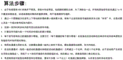
图23A和图23B示出了用于加载传感器数据矢量的算法组件和矢量。23A and 23B show the algorithm components and vectors used to load the sensor data vectors.
图24A和图24B示出了用于设备的操作的算法的又一变体。24A and 24B illustrate yet another variation of the algorithm for operation of the device.
图25A和图25B示出了在四个磁力仪上使用所有八个通道的算法的又一变体。Figures 25A and 25B show yet another variation of the algorithm using all eight channels on four magnetometers.
图25C和图25D示出了从印刷电路板上的硬件到传感器数据矢量的通道映射。Figures 25C and 25D show channel mapping from hardware on a printed circuit board to sensor data vectors.
图26A和图26B示出了算法的又一变体,其中如果任何通道失去连接,磁力仪可以被切换。Figures 26A and 26B show yet another variation of the algorithm in which the magnetometer can be switched if any channel loses connection.
图27示出了算法的又一变体,该算法可以循环通过两个磁力仪的四个通道。Figure 27 shows yet another variation of the algorithm that can cycle through the four channels of the two magnetometers.
图28示出了可用于重置测试棒的灵敏度的算法。Figure 28 shows an algorithm that can be used to reset the sensitivity of the test stick.
图29示出了可用于为较慢的运动信号提供额外的时间来注册并帮助阻止较快的磁力仪信号拾取的运动的算法。Figure 29 shows an algorithm that can be used to give slower motion signals additional time to register and help prevent motion picked up by faster magnetometer signals.
图30A示出了可用于通过在使用测试棒期间使灵敏度轮静音(silent)来减少串扰(cross-talk)的算法。Figure 30A shows an algorithm that can be used to reduce cross-talk by silent the sensitivity wheel during use of the test stick.
图30B-30H示出了用于用灵敏度轮旋转电位计调整灵敏度以及指示灵敏度水平变化的算法。Figures 30B-30H illustrate the algorithm for adjusting sensitivity with the sensitivity wheel rotary potentiometer and indicating changes in sensitivity level.
图31示出了可用于根据从加速度计和陀螺仪接收的数据来计算信号的算法。Figure 31 shows an algorithm that may be used to compute signals from data received from accelerometers and gyroscopes.
图32示出了执行指令以计算运动阻断信号的算法。Figure 32 shows an algorithm for executing instructions to calculate a motion blocking signal.
图33示出了可用于计算灵敏度轮阶跃变化阈值的算法。Figure 33 shows an algorithm that can be used to calculate the sensitivity wheel step change threshold.
图34A示出了用于感应磁性材料的替代方法的流程图。Figure 34A shows a flowchart of an alternative method for sensing magnetic materials.
图34B示出了根据本设备使用的一个或多个磁力仪的通道的实例。Figure 34B shows an example of the channels of one or more magnetometers used in accordance with the present device.
图34C示出了显示卡尔曼滤波(Kalman filtering)过程的示例性软件指令。FIG. 34C illustrates exemplary software instructions showing the Kalman filtering process.
图34D和图34E示出了具有传感器体系类(sensor universe class)的算法,该算法包括用于处理传感器数据的各种变量、函数和属性,并且可以包括缩放范围(scalingrange)。Figures 34D and 34E illustrate algorithms with a sensor universe class that includes various variables, functions, and properties for processing sensor data, and may include scaling ranges.
图34F至图34K示出了用于卡尔曼滤波过程的函数的实例。34F-34K illustrate examples of functions for the Kalman filtering process.
图34L列出了上述算法的示例方法步骤。Figure 34L lists example method steps for the algorithm described above.
图35A至图35H示出了卡尔曼滤波过程的各个阶段的输出。Figures 35A-35H show the output of various stages of the Kalman filtering process.
图36A至图36C示出了磁力仪通道对随时间变化的各种比率。Figures 36A-36C show various ratios of magnetometer channel pairs over time.
图36D至图36F示出了通道配对功能的算法的相关部分。Figures 36D to 36F show relevant portions of the algorithm for the channel pairing function.
图36G示出了用于比率计算的相反通道对和紧密伙伴通道对(close partnerchannel pair)的分组。Figure 36G shows the grouping of opposite channel pairs and close partner channel pairs for ratio calculation.
图36H示出了不同类型的配对信号的实例。Figure 36H shows examples of different types of pairing signals.
图37至图39为用于使用设备的变体对含铁或磁性材料的检测进行感应和警报的算法的变体的过程图。37-39 are process diagrams of variations of algorithms for sensing and alerting on detection of ferrous or magnetic material using variations of devices.
图40为示出带通滤波器(band pass filter)信号的变体的图。FIG. 40 is a diagram showing a modification of a band pass filter signal.
图41和图42分别为示出有和没有增益滤波器的信号图。41 and 42 are diagrams showing signals with and without gain filters, respectively.
图43为示出与经阈值滤波器处理后的信号叠加的信号的变体的图。FIG. 43 is a graph showing a variation of a signal superimposed with a threshold-filtered signal.
图44为示出由设备的变体所获得的数据集的变体的图。FIG. 44 is a diagram showing variations of data sets obtained by variations of devices.
图45为检测含铁或磁性物体的变体的工艺流程图。Figure 45 is a process flow diagram for detecting variants of ferrous or magnetic objects.
具体实施方式Detailed ways
图1A-1B示出了一种金属检测设备100,其包括手柄102、从手柄102延伸出来的杆131以及位于杆131的远端的远端感应部分136。远端感应部分136可以由传感器外壳141覆盖。金属检测设备100可以称为尖锐物探测器、外科金属检测器、RSI检测器或它们的任何组合。FIGS. 1A-1B illustrate a
远端感应部分136可以用作设备100的远端尖端(distal tip)或远端末端(distalend)。如图1A-1B所示,柔性部分145可以将杆131连接到远端感应部分136或远端感应部分136的传感器外壳141。正如将在下面的部分中详细讨论的那样,柔性部分145可以被配置成弯曲或弯折,以便当柔性部分145弯曲时,远端感应部分136更靠近杆131。
图1A示出了杆131相对于杆131的纵向轴线104可旋转。柔性部分145的弯曲和杆131的旋转可以使设备100的操作者(例如外科医生或其他医疗专业人员)通过在患者的体内或器官周围导航(navigating)来进行RSI或其他铁磁性物体的体内检测。FIG. 1A shows that the
传感器外壳141、柔性部分145和杆131可以由生物相容性材料制成。在一些变体中,杆131可以部分地由金属材料、聚合物材料或它们的组合制成。杆131可以部分地由铁磁性金属制成。杆131可以部分地由不锈钢制成。The
传感器外壳141可以由不干扰由传感器外壳141内的传感器进行的磁场测量的材料制成。在一些变体中,传感器外壳141可以由非铁磁性金属材料、聚合物材料或它们的组合制成。例如,传感器外壳141可以部分地由钛制成。在其他变体中,传感器外壳141可以部分地由铝或铝合金制成。在其他变体中,传感器外壳141可以部分地由液晶聚合物制成。传感器外壳141可以部分地由外科或医疗级聚四氟乙烯(PTFE)、聚碳酸酯(PC)、聚醚醚酮(PEEK)或它们的组合制成。The
柔性部分145可以部分地由生物相容性弹性材料制成。在一些变体中,柔性部分145可以部分地由热塑性弹性体制成。例如,柔性部分145可以部分地由聚醚嵌段酰胺制成。更具体地说,柔性部分145可以部分地由
图1B示出了传感器外壳141可以具有壳体长度尺寸140。壳体长度尺寸可以在约40.0mm至约50.0mm之间。例如,壳体长度尺寸140可以为约45.0mm(更具体地说,约45.70mm)。FIG. 1B shows that
在其他变体中,壳体长度尺寸140可以小于40.0mm或大于50.0mm。正如将在以下部分中详细讨论的那样,传感器外壳141的尺寸可以设计为适合两个重力梯度仪或至少四个磁力仪、多个运算放大器、惯性测量单元、LED和其他电子部件。In other variations,
柔性部分145可以具有柔性部分长度尺寸146。柔性部分长度尺寸146可以在约40.0mm至约60.0mm之间。在一些变体中,柔性部分长度尺寸146可以为约50.0mm。例如,柔性部分长度尺寸146可以为约50.8mm。
杆131可以具有杆长度尺寸132。杆长度尺寸132可以为杆131的暴露部分的长度。杆长度尺寸132可以在约300.0mm至约400.0mm之间。在一些变体中,杆长度尺寸132可以在约325.0mm至约375.0mm之间。例如,杆长度尺寸132可以为约350.0mm。
杆131的一段可以延伸到手柄102中。当包括手柄102内的杆131的段时,杆131的整个长度可以为约400.0mm至约500.0mm(例如,约450.0mm)。A section of
杆131可以是空心的,或者包括至少一个适合电缆、杆(rods)、电线或通信线穿过杆131并允许手柄102和远端感应部分136、柔性部分145或它们的组合之间的机械和/或电通信的腔体。在其他变体中,杆131可以包括多个腔体。
杆131可以沿其长度方向是完全刚性的。在其他变体中,杆131可以沿其整个长度是柔性的,从而杆可以弯曲或符合体腔的形状。杆131除了沿其长度方向的一个或多个柔性区域之外可以是刚性的。
在一些变体中,杆131可以直接连接到远端感应部分136或覆盖远端感应部分136的传感器外壳141,而没有柔性部分145。在其他变体中,设备100可以包括柔性部分145的多个实例,从而设备100的超出杆131的远端段可以向多个方向弯曲。在一些变体中,柔性部分145的多个实例可以沿着杆131的长度散置(interspersed),使得杆131的刚性段由柔性部分145连接。In some variations,
手柄102可以包括左手柄外壳101和右手柄外壳103。左手柄外壳101和右手柄外壳103可以通过紧固件(例如螺钉)、粘合剂、过盈配合(interference fit)或它们的组合结合在一起以形成手柄102。手柄102可以包括手柄腔,用于容纳用于操作设备100的某些电子和/或机械部件。手柄102的尺寸可以设计为允许用一只手抓握手柄102。The
手柄102,包括左手柄外壳101和右手柄外壳103,可以部分地由聚合物材料、金属材料或它们的组合制成。例如,手柄102可以由如聚碳酸酯等刚性聚合材料制成。The
应当理解,对手柄102、杆131、柔性部分145、传感器外壳141或它们的组合的实际尺寸、形状或配置没有限制。例如,设备100可以被设计成或定制尺寸为由外科医生或其他医疗专业人员手持使用,使得手柄102可以被外科医生或医疗专业人员用一只手抓握。在其他变体中,设备100可以专门为通过机器人手术系统实施而修改,以便设备100的任何部分可以与机器人手臂集成或易于被机器人手臂抓取。It should be understood that there is no limitation on the actual size, shape or configuration of the
图2A-2B示出了手柄102可以包括触发器105、时钟环107、机头罩109、一个或多个灵敏度轮115、测试棒滑块117和透光窗147。触发器105可以设置在手柄102的底面。触发器105可以由触发器护罩(triggerguard)106保护。2A-2B illustrate that
正如将在以下部分中详细讨论的那样,用户可以挤压触发器105以控制柔性部分145的弯曲。响应于触发器105的挤压,柔性部分145可以弯曲到90°(例如,参见图3B)或超过90°。当柔性部分145被弯曲时,远端感应部分136可以被定位为更接近杆131的远端。As will be discussed in detail in the following sections, the user can squeeze the
金属检测设备100可以被配置为即使在柔性部分145被弯曲时也能承担铁磁性RSI或其他铁磁性物体的体内检测。例如,金属检测设备100可以被配置为即使柔性部分145弯曲约1°至约90°之间或超过90°时也能承担铁磁性RSI或其他物品的体内检测。传统的外科金属检测器的一个技术问题是,这种检测器通常是刚性的、不可弯曲的,并且这种检测器的操作者(例如,外科医生或其他医疗专业人员)只能通过用手轴向平移或沿其纵轴旋转检测器来操纵检测器。这限制了这种检测器的运动范围和它们的检测能力。例如,这种检测器往往不能检测器官周围或不能伸入某些血管。本文公开的金属检测设备100即使在设备100的部分细长段弯曲或弯折时也能承担检测。
时钟环107可以被配置为在被推(urged)入解锁位置时进行旋转。时钟环107可以与杆131结合。旋转时钟环107可以使杆131旋转。旋转和解锁时钟环107将在以下部分中详细讨论。
机头罩109可以用作手柄102的远端帽。当时钟环107旋转时,机头罩109可以用作时钟环107的接收和支承表面。The
一个或多个灵敏度轮115和测试棒滑块117可以定位在触发器105的上方,以允许操作者(例如外科医生或其他医疗专业人员)在握住手柄102并挤压触发器105的同时操纵测试棒滑块117、灵敏度轮115或它们的组合。One or
图2A示出了设备100可以包括定位在测试棒滑块117的相对侧边上的两个灵敏度轮115。这可以使设备100易于被右利手操作者和左利手操作者手持和操纵。FIG. 2A shows that
可以拨动(例如,向前或远端旋转和向后或近端旋转)灵敏度轮115以调整检测灵敏度。正如将在以下部分中详细讨论的那样,调整灵敏度轮115可以调整设备100的检测灵敏度。例如,调整灵敏度轮115可以提高或降低编程的检测阈值。例如,调整灵敏度轮115可以调整设备100的操作模式,从而以不同方式处理检测信号。在检测过程中,设备100的操作者或用户可以在不同的操作模式(例如,高速和高灵敏度模式或低速和低灵敏度模式)之间切换。
测试棒滑块117可以向前(向远端)或向后(向近端)滑动,以使测试棒133(例如,参见图4A-4B和图5B-5D)进入或离开传感器外壳141。测试棒滑块117可以安装在左手柄外壳101和右手柄外壳103之间。测试棒133和测试棒滑块117将在以下部分中更详细地讨论。The
透光窗147可以允许由手柄102内的照明组件(例如LED)产生的光对操作者可见。透光窗147可以被称为光管或光条。透光窗147可以由透光聚合物材料(例如,丙烯酸聚合物)、陶瓷材料或它们的组合制成。通过透光窗147可见的光线可以向操作者提供关于电池寿命、待机指示、错误警告、检测状态或它们的组合的有用信息。Light
图3A和图3B分别示出了设备100的柔性部分145处于拉直配置142和弯曲配置144。如图3B所示,当柔性部分145处于弯曲配置144时,远端感应部分136可以定位为更接近杆131(即,杆131的远端段)。3A and 3B illustrate the
柔性部分145可以被远端管接头139和近端管接头143支撑(bracketed)。远端管接头139可以将柔性部分145与远端感应部分136或覆盖远端感应部分136的传感器外壳141结合。近端管接头143可以将柔性部分145与杆131结合。远端管接头139和近端管接头143可以用作柔性部分145的末端。
正如将在以下部分中详细讨论的那样,杆131内的拉线135(例如,参见图4B和图5D)可以贯穿杆131和柔性部分145的长度,并且拉线135的远端可以接地或以其他方式结合到远端管接头139。例如,拉线135可以穿过远端管接头139中的孔,并打结,以将拉线135的远端固定在远端管接头139上。在其他变体中,可以使用套圈(ferrule)或其他类型的环、帽或夹子来将拉线的远端固定到远端管接头139上。As will be discussed in detail in the following sections, a
拉线135的近端可以与触发器105结合。例如,拉线135的近端可以缠绕在触发器105内的线轴(spool)上。The proximal end of
挤压触发器105可以拉动拉线135,并将柔性部分145弯曲成弯曲配置144。柔性部分145可以足够柔性,以允许在任何期望的方向上弯曲。Squeezing
当释放触发器105时,柔性部分145可以通过柔性部分145内的一个或多个结构被偏压(biased)回到拉直配置142。例如,柔性部分145可以被延伸通过柔性部分145的弹簧管137(例如,参见图4A-4B、图5A-5B和图5D)偏压或以其他方式推回拉直配置142。When
柔性部分145可以响应于对触发器105的挤压而弯曲至90°或超过90°。例如,当触发器105被挤压时,柔性部分145可以相对于其拉直配置142弯曲约30°、约45°、约60°或约90°。当触发器105被更用力地挤压时,柔性部分145可以弯曲约95°、约100°、约105°、约110°、约115°或约120°。The
在其他变体中,触发器105可以用如一个或多个杠杆、轮、旋钮、拉杆或它们的组合等的另一种类型的机械致动器代替。在其他变体中,触发器105可以用如一个或多个按钮、开关或它们的组合等电致动器代替。In other variations, trigger 105 may be replaced with another type of mechanical actuator, such as one or more levers, wheels, knobs, pull rods, or combinations thereof. In other variations, trigger 105 may be replaced with an electrical actuator such as one or more buttons, switches, or combinations thereof.
图3A和图3B示出了传感器外壳141可以具有外壳直径138。外壳直径138可以在约3.0mm至约10.0mm之间。例如,外壳直径138可以为约5.0mm。3A and 3B illustrate that the
柔性部分145可以具有柔性部分直径。柔性部分直径可以在约3.0mm至约10.0mm之间。例如,柔性部分直径可以为约5.0mm。The
杆131可以具有杆直径。杆直径可以在约3.0mm至约10.0mm之间。例如,杆直径可以为约5.0mm。
当外壳直径138、柔性部分直径和轴直径均为约5.0mm时,设备100的细长段(包括传感器外壳141、柔性部分145和杆131)可以安装在标准外科套管内。这可以使设备100用于腹腔镜手术、开放手术或机器人手术。The elongated section of device 100 (comprising
可以用金属抓手移动远端尖端,以便可以准确和精确地控制它。图3C和图3D公开了鸭嘴(duckbill)134和抓手148,其与远端尖端一起移动,以便不影响磁场。通常情况下,金属抓手会影响磁场,并因与远端尖端如此接近而导致不准确的读数。然而,如图3C和图3D所示,远端尖端可以用金属抓手148夹住并移动,以使设备在信号贡献被高通滤波器过滤掉后忽略抓手的相对磁场。这是通过滤除稳态信号,然后观察到来自针和/或其他不锈钢物体的磁场畸变(magnetic field distortion)而发生的。该算法使用的是导数(derivates)或高通滤波信号或两者的组合,所有这些都不会随着时间的推移保持稳定的信号,因为所有的稳定信号要么是因为物体和传感器之间没有相对运动,要么是因为高通滤波器而都会衰减为零。既然如此,那么磁性或不锈钢抓手148在远端尖端抓取并保持不动,并且相对于远端尖端不移动,应该只在连接和移除时产生信号,抓手和远端尖端之间没有运动的稳定信号应该逐渐消失。如果抓手148小心翼翼地握住远端尖端而不滑落,然后将远端尖端移过搜索区域,这应该可以使抓手148得到使用。搜索的对象如针会产生信号,但移动的抓手不能产生信号,因为由于移动的抓手和远端尖端在一起移动,抓手没有相对于远端尖端移动,并且抓手接近时产生的原始信号已经消逝。The distal tip can be moved with a metal gripper so that it can be controlled accurately and precisely. Figures 3C and 3D disclose a
图4A示出了手柄102的侧视图,其中移除了左手柄外壳101,以便查看手柄102内的某些部件和机构。图4A示出了手柄102可以包括手柄印刷电路板(PCB)123。手柄PCB 123可以从手柄102的手柄握把114延伸到手柄筒116。FIG. 4A shows a side view of the
手柄PCB 123可以是刚性的PCB。在其他变体中,手柄PCB 123可以是柔性PCB。The
手柄PCB 123可以用作安置在手柄102内的电子元件的主电路板。如图4A所示,微控制器185、扬声器181和某些电位计可以结合到手柄PCB123。The
微控制器185可以包括一个或多个处理器和存储单元。微控制器185的一个或多个处理器可以被编程为执行存储在存储单元中的指令,以便除其他事项外,确定设备100的某些组件的运动,测试设备100的功能,基于由磁力仪进行的磁场测量获得和处理检测信号,并基于如此处理的检测信号检测RSI或其他铁磁物体。
在一些变体中,微控制器185可以是基于低功率精简指令集计算机(基于RSIC)的微控制器。微控制器185可以是8位(bit)微控制器。在其他变体中,微控制器可以是16位或32位微控制器。例如,微控制器185可以是由微芯科技公司(Microchip Technology Inc.)分销的ATmega32U4微控制器。In some variations,
微控制器185可以包括闪存、静态随机存取存储器(SRAM)、电可擦除可编程只读存储器(EEPROM)或它们的组合。例如,微控制器185可以包括至少32KB的闪存、2.5KB的SRAM和1KB的EEPROM。
微控制器185可以具有在16MHz下的至少16MIPS的CPU速度。在其他变体中,微控制器185可以具有在33MHz下的28MIPS或在40MHz下的36MIPS的CPU速度。
微控制器185可以包括模数转换器(ADC)。例如,微控制器185可以包括12通道的10位ADC。在其他变体中,微控制器185可以包括12位ADC或16位ADC。ADC可以将从磁力仪获得的电压数据(0V至约5V)转换成数字数据。例如,从磁力仪和其他传感器获得的电压数据可以转换为任意的信号库单位(signal bin units)(参见,例如图13-17B)。
虽然在图4A和图4B中没有显示,但根据本申请内容,考虑到手柄102还可以包括惯性测量单元(IMU)。IMU可以提供最多六个自由度(DoF)。IMU可以是六轴IMU,包括三轴加速度计和三轴陀螺仪。IMU可以测量三个垂直轴上的倾斜和角速率以及加速度。在一些变体中,IMU可以是低功率和低噪音的16位IMU。例如,IMU可以是博世传感器有限公司(BoschSensortec GmbH)提供的BMI055、MBI088或BMI160 IMU。IMU可以是图6和图7A-7C中所示的IMU 159的另一个实例。IMU可以是手柄PCB123。Although not shown in FIGS. 4A and 4B , it is contemplated that the
从IMU获得的数据可以被用作与手柄102的运动相关的任何计算的一部分。例如,从IMU 159以及电位计获得的数据可用于确定操作者(例如外科医生或其他医疗专业人员)是否摇晃或晃动了手柄102或是否过快移动了手柄102。微控制器185的一个或多个处理器可以被编程为执行进一步的指令,以基于从3轴加速度计获得的加速度数据和从3轴陀螺仪获得的旋转数据,而不考虑手柄102的突然运动或超过一个或多个运动阈值的运动。Data obtained from the IMU may be used as part of any calculations related to the motion of the
设备100可以包括结合到手柄PCB 123的若干输出组件。输出组件可以包括一个或多个灯和/或音频组件。输出组件可以被配置为生成用户输出(例如,声音和/或光)以提醒用户检测到RSI或铁磁性物体。输出组件也可以被配置为生成用户输出,以指示设备100的功能或操作状态。例如,用户输出可以由输出组件生成以传达关于设备100的电池寿命、待机指示、错误警告、检测状态或它们的组合的信息。
输出组件可以包括扬声器181、近端发光二极管(LED)173、远端LED 183(参见图6A)或它们的组合。扬声器181和/或近端LED 173可以结合到手柄PCB 123上。在其他变体中,只有扬声器181可以结合到手柄PCB 123上。The output components may include a
如图4A所示,扬声器181可以定位在手柄握把114内。在其他变体中,扬声器181可以被定位在手柄筒116内。As shown in FIG. 4A ,
扬声器181可以被配置为传送声音或音频信息,以通知操作者检测到RSI或其他铁磁性物体,或传达关于设备100的功能或操作状态的信息。例如,扬声器181可以产生声音或音频消息以传达关于设备100的电池寿命、待机指示、错误警告、检测状态或它们的组合的信息。
该声音可以是嘟嘟声、铃声、钟声、音调声或它们的组合。该音频消息可以是预先录制的信息或短语。The sound may be a beep, ring, chime, tone, or a combination thereof. The audio message may be a pre-recorded message or phrase.
近端LED 173可以定位在手柄筒116内。在其他变体中,近端LED 173可以定位在靠近机头罩109或沿着手柄握把114的地方。
手柄102可以进一步包括透光窗147。透光窗147可以直接定位在近端LED 173上方或靠近近端LED 173。透光窗147可以使近端LED 173产生的光对操作者可见。透光窗147也可以被称为光管或光条。透光窗147可以由透光聚合物材料(如丙烯酸聚合物)、陶瓷材料或它们的组合制成。The
设备100还可以包括远端LED 183。远端LED 183可以结合到远端感应部分136中的柔性电路或电路板上(参见图6A)。传感器外壳141可以包括透光窗或透光部分,以允许由远端LED 183产生的光通过内窥镜对操作者可见。
远端LED 183的功能可以与近端LED 173的功能类似。由近端LED 173产生的相同的光或光模式也可以由远端LED 183产生(反之亦然)。由近端LED 173和/或远端LED 183产生的光或光模式可以传达有关设备100的电池寿命、待机指示、错误警告、检测状态或它们的组合的信息。例如,近端LED 173、远端LED 183或它们的组合还可以通过强度和/或占空比(duty cycle)的变化来提供关于剩余电池寿命和或其他各种状态和信息的指示,(例如,当电池即将电量耗尽时闪烁红色,当电池已经电量耗尽时保持红色,当设备正在开机时发出明亮的白光,不同颜色表示不同的灵敏度水平等)。作为一个更具体的实例,为了指示剩余的电池寿命,当电池达到其寿命的一半时,快速的单光(例如红色的光)可以闪烁(近端LED 173和远端LED 183中的至少一个)。然后,当电池达到其寿命的3/4时,该灯(近端LED173和远端LED183中的至少一个)可以快速闪烁两次(例如,双闪)。然后,当电池达到其寿命的85%时,该灯(近端LED 173和远端LED 183中的至少一个)可以快速闪烁三次,并且一旦电池经过了其寿命的95%并且设备100正准备关闭时,该灯可以最终缓慢地闪烁(例如,红色的光可以缓慢地闪烁)。The function of the far-
在又一个实例中,该设备可以使远端尖端和手柄的LED灯均为浅蓝色,并且在警报信号高于阈值时保持点亮。在另一个实例中,当警报信号的大小增加超过警报阈值时,蓝色LED可以快速循环开启和关闭以显得更亮,并且在每个周期中的更多时间保持开启。在另一个实例中,在测量时间(例如,每5秒或10秒)之后的心跳LED指示可以指示设备仍然处于活动状态,并且可以是短暂的绿色闪烁或其他颜色和/或闪烁或持续时间的开和关模式。此外,当一次性设备中的电池接近其寿命终点时,设备100可以被配置成这样的算法,使得当功率(power)开始下降到某个阈值以下时,或当功率以设备复位或以某种方式记录功率下降或电源循环这样的方式闪烁时,这一事件可以被写入EEPROM和或其他板载存储器和或辅助存储器,例如SD卡,以使像这样的功率骤降或功率循环事件或多个这样的事件可以被记录下来,在通电或功率激增超过最初下降的功率水平时,一定数量的记录功率骤降或功率循环事件可以阻止设备再次运行,而不是仅仅闪烁LED 173来指示低电池电量或接近电池寿命终点。这样的算法可以帮助补救这样的情况,即电池没电发出电池寿命结束的信号,设备停止工作,然后当它停止工作时,电池的功率消耗减少,然后电池能够达到足够高的水平来重新启动设备,并可能重复这个循环不止一次。通过监测这一点并结束设备操作,用户更清楚地知道一次性设备已经没电,他们应该得到新的设备进行额外的调查,而不是看着它没电,然后在电量最终耗尽时重新启动一次或多次。In yet another example, the device can cause both the distal tip and handle LED lights to be light blue and remain on when the alarm signal is above a threshold. In another example, when the magnitude of the alarm signal increases beyond the alarm threshold, the blue LED can be cycled on and off rapidly to appear brighter, and remain on for more of the time in each cycle. In another example, a heartbeat LED indication after a measured time (e.g., every 5 or 10 seconds) may indicate that the device is still active, and may be a brief green blink or other color and/or blink or duration On and off mode. Additionally, when a battery in a disposable device approaches the end of its life, the
例如,近端LED 173和远端LED 183都可以产生绿色的闪烁光模式(心跳光模式),以指示设备100处于工作状态。近端LED 173可以产生红色的闪烁光模式,以通知操作者,传感器外壳141内的一个或多个电子部件或传感器断开连接,或者整个传感器外壳141已经断裂或断开连接。当传感器外壳141内的一个或多个电子部件或传感器断开连接或整个传感器外壳141断裂或断开连接时,扬声器181也可以产生警告声。For example, both the near-
当检测信号高于灵敏度阈值或检测阈值时,扬声器181也可以产生嘟嘟声或嘟嘟声模式,以通知操作者设备100可能已经检测到RSI或其他铁磁性物体。由扬声器181产生的声音(例如,嘟嘟声或嘟嘟声模式)可以对应于高于灵敏度阈值或检测阈值的检测信号的大小。例如,当灵敏度阈值或检测阈值以上的检测信号的大小超过预定的大小阈值时,扬声器181可以产生更大的嘟嘟声或嘟嘟声模式的实例。当检测信号高于灵敏度阈值或检测阈值时,近端LED 173、远端LED 183或它们的组合也可以产生光或光模式(例如,持续的蓝光或闪烁的蓝光)。在一些变体中,由近端LED 173、远端LED 183或它们的组合产生的光或光模式的亮度可以对应于高于灵敏度阈值或检测阈值的检测信号的大小。例如,当灵敏度阈值或检测阈值以上的检测信号的大小超过预定的大小阈值时,近端LED 173、远端LED 183或它们的组合可以产生更亮的光或光模式的实例。在一些变体中,由近端LED 173和/或远端LED 183产生的光的颜色(例如,红光、蓝光和/或绿光)和产生的光模式可以被映射到不同的信号。任何一系列不同的颜色可被视为不同信号大小和频率的指示器。
图4A还示出了设备100可以包括被配置为向设备100及其各种电子部件供电的电源。在一些变体中,该电源可以是便携式电源,例如一个或多个电池149。如图4A所示,一个或多个电池149可以被安置在手柄102内。例如,手柄握把114可以包括电池座或电池容纳室,该电池座或电池容纳室包括正极电池端子125和负极电池端子127。FIG. 4A also shows that
在一些变体中,电池149可以是可充电电池。在这些变体中,设备100可以包括用于从外部电源接收电以对电池149充电的输入。在另外的变体中,设备100可以包括用于从外部电源接收电的输入,并且设备100可以完全由外部电源供电而不使用电池149。In some variations,
如图4A和图4B所示,手柄102可以进一步包括触发器105、与触发器105的至少一部分结合的触发器电位计171以及触发器弹簧121。拉线135的近端段可以结合到触发器105的至少一部分。As shown in FIGS. 4A and 4B , the
触发器105可以被驱动以控制柔性部分145的弯曲。如前所述,触发器105可以通过延伸穿过杆131和柔性部分145的拉线135连接到柔性部分145。挤压触发器105会拉动拉线135,并使柔性部分145弯曲。弯曲柔性部分145使远端感应部分136更接近杆131。The
如图4B所示,触发器105可以包括拉线孔165。拉线135可以延伸通过拉线孔165,并在拉线孔165处被捆绑或以其他方式固定到触发器105上。在其他变体中,拉线135的近端段或末端可以延伸到触发器105内的空腔中,并缠绕在触发器105内的线轴上。拉线135也可以通过粘合剂、夹子、扎带(tie)、套圈或它们的组合连接到触发器105。As shown in FIG. 4B , the
如前所述,拉线135可以贯穿杆131和柔性部分145的长度,并且拉线135的远端可以被绑住或以其他方式结合到设备100的远端的远端管接头139。Pull
例如,拉线135可以穿过限定在远端管接头139中的孔,并且可以打结以将拉线135的远端固定到远端管接头139。在其他变体中,可以使用套圈或其他类型的环、帽或夹子将拉线的远端固定到远端管接头139上。For example, pull
在一些变体中,拉线135可以是编织的电缆或电线,例如编织的不锈钢电缆。在其他变体中,拉线135可以是聚合物电缆或导线,如尼龙电缆或导线。In some variations, pull
触发器弹簧121可以对触发器105进行弹簧加载,从而使触发器105在被挤压后返回到其起始位置。触发器弹簧121可以是扭力弹簧。触发器弹簧121可以与手柄102内部的特征相配合以提供阻力。
挤压触发器105可以拉动拉线135,并将柔性部分145弯曲成弯曲配置144。柔性部分145可以足够柔性,以允许在任何所期望的方向弯曲。Squeezing
当触发器105被释放时,柔性部分145可以通过柔性部分145内的一个或多个结构被偏压回拉直配置142。例如,柔性部分145可以被延伸通过柔性部分145的弹簧管137(例如,参见图4A-4B、图5A-5B和图5D)偏压或以其他方式推回拉直配置142。When
在其他变体中,触发器105可以用另一种类型的机械致动器,例如一个或多个杠杆、轮、旋钮、拉杆或它们的组合代替。在另外的变体中,触发器105可以用如一个或多个按钮、开关或它们的组合等电致动器代替。In other variations, trigger 105 may be replaced with another type of mechanical actuator, such as one or more levers, wheels, knobs, pull rods, or combinations thereof. In further variations, trigger 105 may be replaced with an electrical actuator, such as one or more buttons, switches, or combinations thereof.
图4B示出了手柄102的特写侧视图,为了便于观察,将左手柄外壳101、触发器弹簧121和灵敏度轮115移除。图4B示出了触发器电位计171可以与触发器105的可旋转部分结合。例如,触发器电位计171可以与延伸通过触发器电位计171的触发器轴(在图4B中不明显)结合。Figure 4B shows a close-up side view of
触发器电位计171可以是旋转电位计。在一些变体中,触发器电位计171可以安装到手柄PCB 123的一部分上。在其他变体中,触发器电位计171可以安装在手柄102内的另一个PCB上。
触发器电位计171可以提供有关触发速度(例如,触发器被拉动的速度)的数据。由于弯曲柔性部分145使远端感应部分136经受突然的运动并使远端感应部分136更接近铁磁杆131,所以触发器电位计171提供可用于调整灵敏度阈值或检测阈值的数据。
例如,微控制器185的一个或多个处理器可以被编程为提高灵敏度阈值或检测阈值(即,降低检测灵敏度),以解决当远端感应部分136向杆131弯曲时由杆131引起的任何磁场畸变和/或远端感应部分136的任何突然运动。例如,从触发器电位计171获得的数据也可用于确定操作者是否通过过于用力或快速地挤压触发器105而抽动(jerk)或拉动(yank)了远端感应部分136。For example, one or more processors of
可以提高灵敏度阈值或检测阈值(也被称为降低(lowering)或减少(decreasing)检测水平或灵敏度水平)以避免假阳性信号。当触发器被挤压或以其他方式移动得太快时,这会在检测到的磁场中产生尖锐的尖峰(spike)。在这些情况下,微控制器185的一个或多个处理器可以被编程为执行指令,以确定触发器运动超过触发器运动阈值或触发器运动阈值范围,然后一个或多个处理器可以被编程为响应于触发器105的突然或不受控制的运动而执行进一步的指令,以提高编程的灵敏度阈值或检测阈值(即,降低设备100的灵敏度水平)以。这样做的目的是为了防止或干预(tamper)任何假阳性信号。以这种方式,从触发器电位计171获得的数据可以被计入由微控制器185运行的检测算法中。The sensitivity threshold or detection threshold (also referred to as lowering or decreasing the detection level or sensitivity level) can be increased to avoid false positive signals. When the trigger is squeezed or otherwise moved too quickly, this produces a sharp spike in the detected magnetic field. In these cases, one or more processors of
手柄102可以进一步包括一个或多个灵敏度轮115,其被配置为响应灵敏度轮115的旋转而调整编程的灵敏度阈值或检测阈值。灵敏度轮115的至少一部分可以从沿手柄外壳限定的切口中突出,以允许操作者拨动或旋转灵敏度轮115。The
操作者可以拨动或旋转灵敏度轮115,以便提高或降低编程的灵敏度阈值或检测阈值。例如,操作者可以向前(或向远端方向)拨动或以其他方式旋转至少一个灵敏度轮115以提高设备100的灵敏度水平。提高设备100的灵敏度水平,可以使设备100更准确地检测到受试者身体内存在的小的或弱磁化的RSI或其他铁磁物体的存在。提高设备100的灵敏度水平可以降低编程的灵敏度阈值或检测阈值。The operator can dial or rotate the
操作者可以向后(或向近端方向)拨动或以其他方式旋转至少一个灵敏度轮115以降低设备100的灵敏度水平。降低设备100的灵敏度水平可以增加编程的灵敏度阈值或检测阈值。当来自患者附近的铁磁性医疗设备(例如,金属外科设备或推车)的假阳性信号使操作者难以察觉实际检测信号时,操作者可以降低设备100的灵敏度水平。An operator may dial or otherwise rotate at least one
设备100可以包括若干离散的灵敏度水平。例如,设备100可以包括11个离散的灵敏度水平,默认级别为7级。当灵敏度水平达到上限(例如11级)或下限(例如1级)时,设备100可以生成用户输出(例如两个连续的嘟嘟声或嘟嘟声)。
灵敏度轮115可以旋转地结合到灵敏度旋转电位计169(参见图4B,为了便于查看,在图4B中灵敏度轮115被移除)。灵敏度旋转电位计169可以结合到手柄PCB 123上。
灵敏度旋转电位计169可以提供关于轮旋转的数据,从而提供操作者所期望的灵敏度水平。A
微控制器185的一个或多个处理器可以被编程为执行指令,以使从灵敏度旋转电位计169获得的电位计信号平滑,以减少信号噪音,并观察由于操作者向前或向后拨动灵敏度轮115中的至少一个而产生的连续向上或向下的信号尖峰。微控制器185的一个或多个处理器可以被编程为在检测到两个连续的灵敏度向上的信号尖峰或两个连续的向下的信号尖峰时执行指令,以便调整灵敏度阈值或检测阈值。例如,微控制器185的一个或多个处理器可以被编程为在观察到来自灵敏度旋转电位计169的两个连续的向上信号尖峰时执行指令,以便降低灵敏度阈值或检测阈值(即,提高灵敏度水平)。One or more processors of
设备100的灵敏度水平也可以由设备100自动调整(即,没有操作者的输入)。例如,如果根据从触发器电位计171获得的数据计算出的触发运动超过触发运动阈值,则设备100的灵敏度水平可以降低,并且灵敏度阈值或检测阈值可以增加。另外,例如,当磁力仪被周期性地重置以过滤除任何沉降事件(settling events)或水平变化时,设备100的灵敏度水平可以降低,灵敏度阈值或检测阈值可以提高。例如,可以使用磁力重置功能来周期性地(例如,每5秒)重置磁力仪,以便用电流脉冲重新对齐磁力仪中的磁畴(domains)。这样做是为了防止磁力仪受到强磁场的严重影响。重置磁力仪可能会导致瞬时的信号尖峰或撞击。在重置磁力仪的同时提高灵敏度阈值或检测阈值可以减少出现假阳性信号的可能性。The sensitivity level of
尽管在本实例中提到了灵敏度轮115,但本申请设想且普通技术人员应该理解,灵敏度轮115只是灵敏度致动器的一个实例。在其他变体中,灵敏度致动器可以实施为一个或多个滑块、旋钮、按钮、开关或它们的组合。在其他变体中,灵敏度致动器可以实现为通过电子显示屏或触摸板呈现的用户界面控制。Although reference is made to the
图4A和图4B还示出了手柄102可以包括测试棒滑块117。在一些变体中,测试棒滑块117可以沿着手柄筒116的背侧滑动。测试棒滑块117可以向前(向远端)或向后(向近端)滑动或以其他方式平移,以使测试棒133在杆131内沿轴向平移。向前滑动测试棒滑块117可以将测试棒133向远端延伸或驱动到传感器外壳141中,并接近远端感应部分136的磁力仪。或者,测试棒133的远端至少有一段可以最初定位在传感器外壳141内或略微定位在传感器外壳141内,并且滑动测试棒滑块117可以使测试棒133进一步平移到传感器外壳141内。由于设备100寻找磁场的变化,所以测试棒133的远端可以定位在靠近、远离传感器外壳141中最近端磁力仪或离传感器外壳141中最近端磁力仪的任何距离。4A and 4B also show that the
测试棒133可以部分地由铁磁材料制成。例如,测试棒133可以部分地由铁磁性金属制成。测试棒133可以部分地由磁性不锈钢制成,如铁素体不锈钢、马氏体不锈钢或双相不锈钢。The
测试棒133可以是柔性的和可弯曲的。例如,测试棒133可以实现为柔性的铁磁性电缆或杆。The
测试棒133可以具有已知的磁性特征,这样当测试棒133延伸到传感器外壳141中时,可以考虑由测试棒133引起的磁场畸变。测试棒133可用于验证设备100的功能和/或原位重置磁环境。The
测试棒滑块117可以由拉伸弹簧119弹簧加载,以在未向测试棒滑块117施加远端力时将测试棒滑块117拉回到其默认的起始位置(例如,参见图4B)。拉伸弹簧119的一端可以接地到右手柄102,拉伸弹簧119的另一端可以附接或结合到测试棒滑块117的至少一部分。
测试棒133的近端可以被固定或以其他方式结合到测试棒滑块117。例如,测试棒133的近端可以通过粘合剂、紧固件、扎带、夹子或它们的组合固定到测试棒滑块117的近端部分。The proximal end of the
测试棒133可以部分地容纳在弹簧管137内。测试棒133的远端可以延伸出弹簧管137。弹簧管137的近端可以被固定或以其他方式连接到右手柄外壳103。例如,弹簧管137的近端可以通过粘合剂、紧固件、扎带、夹子或它们的组合固定在右手柄外壳103的特征上。弹簧管137可以从手柄102延伸通过杆131和柔性部分145。The
除了用作测试棒133的外壳外,弹簧管137还可用于在释放触发器105时将柔性部分145偏压回其未弯曲配置144。弹簧管137可以部分由聚对苯二甲酸乙二醇酯(PET)制成。在其他变体中,弹簧管137可以由表现出形状记忆特性的聚合材料或共聚物制成。弹簧管137也可以为柔性部分145提供一定程度的刚度或结构。In addition to serving as a housing for the
容纳测试棒133并将柔性部分145偏压回其未弯曲配置144的弹簧管137可以具有服务于多种功能的相同组件,减少贯穿小直径轴的部件的总数,并降低设备100的复杂性。The
手柄102进一步包括安装或以其他方式结合到手柄PCB 123的滑块电位计167。滑块电位计167可以通过齿轮结合到测试棒滑块117的至少一部分。The
例如,图4A和图4B示出了测试棒滑块117可以结合到配置为与正齿轮129相互作用的齿条齿轮(rack gear)128。正齿轮129可以旋转地结合到滑块电位计167。例如,从正齿轮129延伸出来的齿轮轴可以与滑块电位计167结合。For example, FIGS. 4A and 4B illustrate that
从滑块电位计167获得的数据可用于确定测试棒滑块117的滑块位置。滑块位置可以指示测试棒133相对于远端感应部分136的磁力仪的相对定位。例如,滑块位置可以指示测试棒133相对于第一近端磁力仪202、第二近端磁力仪204、第一远端磁力仪208和第二远端磁力仪210中至少一个的相对定位。Data obtained from
当测试棒133由测试棒滑块117驱动进入传感器外壳141并接近磁力仪时,微控制器185的一个或多个处理器可以被编程为执行指令以进行某些检测诊断。例如,微控制器185的一个或多个处理器可以被编程为执行指令,以将从磁力仪获得的磁场测量值与与铁磁测试棒133相关的已知磁场值进行比较。When
微控制器185的一个或多个处理器可以被编程为执行进一步的指令,以指示输出组件(例如,扬声器181或LED)生成用户输出(例如,声音或光模式),以通知操作者诊断的结果。One or more processors of
测试棒133可以与灵敏度轮115结合使用,以衡量设备100的功能或可操作性。例如,当操作者不确定设备100是否正常运行时,操作者可以通过向前或向远端方向拨动灵敏度轮115并向前推动测试棒滑块117以使铁磁测试棒133进入传感器外壳141并接近磁力仪来提高设备100的灵敏度水平。操作者可以根据设备100在这种情况下产生的用户输出来深入了解设备100的功能。
从滑块电位计167获得的数据也可被用作关于测试棒133的运动(例如,速度和/或加速度)的任何计算或确定的一部分。例如,从滑块电位计167获得的数据可用于确定操作者是否过快地伸出或缩回测试棒133。Data obtained from
当从滑块电位计167获得的数据表明测试棒滑块117正被向前推动以测试设备100的功能时,设备100也可以自动提高灵敏度水平。设备100可以自动提高灵敏度水平(从而降低灵敏度阈值或检测阈值),以提高测试棒133被磁力仪检测到的机会。例如,微控制器185的一个或多个处理器可以被编程为执行指令,以根据从滑块电位计167获得的数据或信号确定测试棒133正在向前推进。微控制器185的一个或多个处理器可以被编程为响应于测试棒133被向前推进或进入传感器外壳141中来执行进一步的指令,以降低灵敏度阈值或检测阈值。The
在其他情况下,测试棒133可用于消除归因于传感环境中的铁磁物体的假阳性信号或噪音。例如,测试棒133可用于消除归因于患者附近的铁磁性医疗设备(例如,金属外科设备或推车)的假阳性信号或噪音。这种噪音会使操作者难以察觉实际的检测信号。例如,希望将磁环境重新归零的操作者可以对测试棒滑块117施加远端力,以使测试棒133延伸到传感器外壳141中,并将测试棒133保持在这个延伸配置中超过预定的时间阈值的一段时间。响应于测试棒133被保持在此延伸配置中,微控制器185的一个或多个处理器可以被编程为执行指令,以通过提高灵敏度阈值或检测阈值来降低设备100的灵敏度水平,直到除了归因于测试棒133的信号之外,大多数(或大量的)假阳性信号低于新的灵敏度阈值或检测阈值。然后,这个新的较高的灵敏度阈值或检测阈值甚至可以在操作者放开测试棒滑块117和测试棒133不再伸入传感器外壳141并处于缩回配置时保持。然后,操作者可以在这个新的较低的灵敏度水平(即用较高的灵敏度阈值或检测阈值)上进行检测。In other cases,
图5A示出了设备100的远端段的等距视图,为了便于观察,移除了传感器外壳141和柔性部分145,测试棒133处于缩回配置130。缩回配置130可以是测试棒133的默认配置。当处于缩回配置130时,测试棒133的远端可以在弹簧管137内。当处于缩回配置130时,测试棒133可以与磁力仪保持足够远的距离,这样测试棒133的磁性就不会对RSI或其他铁磁性金属物体的检测产生显著的影响。FIG. 5A shows an isometric view of the distal section of
图5B示出了图5A所示设备100的同一远端段的等距视图,但测试棒133处于延伸配置134中。当操作者在手柄102上推进测试棒滑块117并对测试棒滑块117施加远端力以将测试棒滑块117保持在推进位置时(例如,通过将操作者的手指保持在测试棒滑块117上),测试棒133可以处于延伸配置134中。当测试棒133处于延伸配置134中时,测试棒133的远端可以从弹簧管137延伸或推进到传感器外壳141中(为便于观察,图5B中未显示)。当处于延伸配置134中时,测试棒133可以足够接近远端感应部分136的磁力仪,以便铁磁测试棒133被至少一个磁力仪检测到(由测试棒133引起的磁场畸变被第一近端磁力仪202、第二近端磁力仪204、第一远端磁力仪208和第二远端磁力仪210中的至少一个检测到)。FIG. 5B shows an isometric view of the same distal section of
当测试棒133处于延伸配置134中时,测试棒133的远端可以与第二近端磁力仪204相隔几毫米。例如,当测试棒133处于延伸配置134中时,测试棒133的远端可以与第二近端磁力仪相隔约1.0mm至约5.0mm。在其他变体中,当测试棒133处于延伸配置134中时,测试棒133的远端可以与第二近端磁力仪204相隔约5.0mm至约10.0mm。在其他变体中,当测试棒133处于延伸配置134中时,测试棒133的远端可以与第二近端磁力仪相隔超过10.0mm或小于1.0mm。在另外的变体中,当测试棒133处于延伸配置134中时,测试棒133的远端可以定位在一个或多个磁力仪之上,但不与磁力仪接触。When
例如,在一些变体中,当测试棒133处于延伸配置134中时,测试棒133的远端可以定位在超过第二近端磁力仪204的约1.0mm处。For example, in some variations, the distal end of
在其他变体中,当测试棒133处于延伸配置134中时,测试棒133的远端尖端可以定位在超过第一近端磁力仪202的约1.0mm处。In other variations, the distal tip of the
在另外的变体中,当测试棒133处于延伸配置134中时,测试棒133的远端尖端可以定位在超过第一远端磁力仪208或第二远端磁力仪210的约1.0mm处。在这些变体中,整个测试棒133可以被定位在磁力仪上方。In a further variation, the distal tip of
图5C示出了设备100的远端段的俯视图,为了便于观察,移除了传感器外壳141和柔性部分145,测试棒133处于延伸配置134中。图5D示出了沿图5C所示的A-A截面的同一远端段的剖视图。5C shows a top view of the distal section of
图5C和图5D示出了细长的柔性电路157可以将远端感应部分136中的一个或多个PCB结合到手柄PCB 123。例如,细长的柔性电路157可以将近端刚性PCB 161结合到手柄PCB123上。细长的柔性电路157允许远端感应部分136内的磁力仪、放大器和其他电子部件与安装在手柄PCB 123上的微控制器185进行电通信。当柔性部分145响应于对触发器105的挤压被拉到弯曲配置144时,通过柔性部分145延伸的细长柔性电路157的段可以弯曲或挠曲(flex)。FIGS. 5C and 5D illustrate that an
细长的柔性电路157或柔性印刷电路可以包括印刷、粘附、层压、沉积和/或以其他方式粘合到柔性聚合物薄膜(例如PET薄膜或聚酰亚胺薄膜)的导电金属箔。在其他变体中,细长的柔性电路157可以是刚性-柔性PCB或具有一些刚性的柔性印刷电路。The elongate
细长的柔性电路157可以定位在弹簧管137和杆131之间,弹簧管137将测试棒133和拉线135部分地容纳在柔性部分145之内。拉线135可以定位在靠近柔性部分145和杆131的底部或腹侧。An elongated
如前所述,拉线135的远端可以接地或以其他方式与远端管接头139结合。如图5D所示,拉线135的远端可以接地或以其他方式结合到在细长的柔性电路157的下方或以下(inferior to)的远端管接头139。As previously mentioned, the distal end of the
例如,拉线135可以穿过限定在远端管接头139上的孔,并且可以打结以将拉线135的远端固定到远端管接头139上。在一些变体中,远端管接头139上的孔可以定位在细长的柔性电路157的下方或以下。在其他变体中,可以使用套圈或其他类型的环、帽或夹子将拉线的远端固定到远端管接头139上。For example, pull
弹簧管137可以定位在更靠近柔性部分145和杆131的顶部或背侧。如图5D所示,弹簧管137的远端可以在细长的柔性电路157的上方或以上(superior to)与远端管接头139结合。
柔性部分145内的管子、电路和电缆的排列可以快速有效地使柔性部分145弯曲,并且可以恢复其未弯曲或拉直配置。例如,柔性部分145内的弹簧管137可以使柔性部分145弹回到其默认的拉直配置。此外,柔性部分145可以弯曲而不对弹簧管137内的测试棒133产生不利影响。The arrangement of tubes, circuits, and cables within the
金属检测设备100可以被配置为即使在柔性部分145弯曲时也能进行测试(例如,功能测试)或重新归零。例如,金属检测设备100可以被配置为即使在柔性部分145弯曲约1°至约90°之间或超过90°时也进行检测或重新归零。到目前为止,据申请人所知,还没有设计出具有可弯曲的测试棒133的外科金属检测器,以便在设备100的细长传感段的一部分被弯曲或弯折时也进行测试或重新归零。
图5A-5D还示出了远端感应部分136可以包括包括第一近端磁力仪202和第二近端磁力仪204的近端重力梯度仪200和包括第一远端磁力仪208和第二远端磁力仪210的远端重力梯度仪206。为本申请的目的,术语磁力仪是指用于测量磁场分量的设备或传感器,术语重力梯度仪是指用于测量磁场分量梯度的此类设备或传感器的组合。5A-5D also show that the
第一近端磁力仪202和第二近端磁力仪204可以被安装或以其他方式结合到近端PCB或电路,并且第一远端磁力仪208和第二远端磁力仪210可以被安装或以其他方式结合到远端PCB或电路。在图5A-5D和图6A-6B所示的变体中,第一近端磁力仪202和第二近端磁力仪204可以被安装或以其他方式结合到近端刚性PCB 161。在这种变体中,第一远端磁力仪208和第二远端磁力仪210可以被安装或以其他方式结合到远端刚性PCB 163。The first
近端刚性PCB 161可以通过远端柔性电路155连接或以其他方式结合到远端刚性PCB 163。在其他变体中,第一远端磁力仪208和第二远端磁力仪210可以被安装或以其他方式结合到柔性电路。Proximal
尽管图5A-5D示出了包括两个重力梯度仪和四个磁力仪的设备100的变体,但本申请设想到,设备100可以包括三个或更多的重力梯度仪或只有一个重力梯度仪。Although Figures 5A-5D illustrate variations of
第一近端磁力仪202可以定位在第二近端磁力仪204的远端。第一远端磁力仪208可以定位在第二远端磁力仪210的远端。The first
第一近端磁力仪202可以与第二近端磁力仪204串联定位在远端,使得第一近端磁力仪202沿纵轴(例如,图1A中所示的纵轴104)定位在第二近端磁力仪204的远端。第一远端磁力仪208可以与第二远端磁力仪210串联定位在远端,使得第一远端磁力仪208定位在第二远端磁力仪210的远端。The first
图5D示出了第一近端磁力仪202可以以近端磁力仪分离距离(proximalmagnetometer separation distance)205与第二近端磁力仪204相分离。在一些变体中,近端磁力仪分离距离205可以在约4.00mm和5.00mm之间。例如,近端磁力仪分离距离205可以在约4.50mm和4.75mm之间。FIG. 5D shows that the first
第一远端磁力仪208可以以远端磁力仪分离距离207与第二远端磁力仪210相分离。在一些变体中,远端磁力仪分离距离207可以在约4.00mm和5.00mm之间。例如,远端磁力仪分离距离207可以在约4.50mm和4.75mm之间。The first
第二远端磁力仪210可以以重力梯度仪分离距离209与第一近端磁力仪202相分离。在一些变体中,重力梯度仪分离距离209可以在约18.00mm和20.00mm之间。例如,重力梯度仪分离距离209可以在约18.50mm和18.85mm之间。The second
申请人面临的一个技术问题是如何设计外科磁性检测器来检测小的或微小的磁性物品,例如小的外科针或在手术中断裂的外科设备的碎片。申请人发现的技术方案是本文所披露的设备100,该设备100具有磁力仪和重力梯度仪,并按照之前提供的尺寸进行定位和间隔。申请人发现,本文公开的分离距离(例如,磁力仪分离距离和/或重力梯度仪分离距离)允许设备100更有效地检测小针或其他小铁磁性尖锐物或物品。A technical problem faced by the applicant is how to design a surgical magnetic detector to detect small or minute magnetic items, such as small surgical needles or fragments of surgical equipment that break during surgery. The solution found by applicants is the
此外,本文所公开的设备100具有根据先前提供的尺寸定位和间隔的磁力仪和重力梯度仪,设备100以及磁力仪的方向,和独特的信号组合,都可以帮助感应感兴趣的物体,并帮助减少因在手术室中移动通过固有磁场线(native magnetic field line)(例如归因于地球、医院建筑、医疗设备等的磁场线)而引起的错误信号的信号大小。In addition, the
远端感应部分136还可以包括惯性测量单元(IMU)159。IMU 159可以提供最多六个自由度(DoF)。IMU 159可以是6轴IMU,包括3轴加速度计和3轴陀螺仪。IMU 159可以测量三个垂直轴上的倾斜和角速率以及加速度。在一些变体中,IMU可以是低功率和低噪音的16位IMU。例如,IMU 159可以是博世传感器有限公司(Bosch Sensortec GmbH)提供的BMI055、MBI088或BMI160 IMU。
从IMU 159获得的数据可以被用作与远端感应部分136的速度和加速度相关的任何计算的一部分。例如,从IMU 159以及电位计获得的数据可用于确定操作者是否已经抽动或拉动了远端感应部分136。微控制器185的一个或多个处理器可以被编程为执行进一步的指令,以根据从3轴加速度计获得的加速度数据和从3轴陀螺仪获得的旋转数据来忽略远端感应部分136和杆131中的至少一个的突然运动。Data obtained from
在一些变体中,IMU 159可以被安装到近端刚性PCB 161。在其他变体中,IMU 159可以被安装到远端刚性PCB 163或远端感应部分136的另一部分。In some variations,
在一些变体中,从IMU 159接收的数据(例如,来自三轴加速度计的加速度数据和/或来自三轴陀螺仪的陀螺仪数据)可以影响设备100是否降低灵敏度水平或检测灵敏度。降低灵敏度水平或检测灵敏度可以涉及提高灵敏度阈值或检测阈值以避免假阳性信号。例如,当从IMU 159接收到的数据表明远端感应部分136正在经历增强或夸张的运动(例如,操作者过快地旋转杆131或过快地挤压/放开触发器)时,这可以在检测的磁场中产生尖锐的尖峰。在这些情况下,微控制器185的一个或多个处理器可以被编程为执行指令,以基于从IMU 159获得的数据(例如,当从IMU 159获得的运动数据超过预定的运动阈值或运动阈值范围时)确定远端感应部分136正在经历增强或夸张的运动,然后一个或多个处理器可以被编程为执行进一步的指令以提高编程的灵敏度阈值或检测阈值,以降低设备100的灵敏度,以响应远端感应部分136的突然或不受控制的运动。可以这样做以防止或干预任何假阳性信号。In some variations, data received from IMU 159 (eg, acceleration data from a three-axis accelerometer and/or gyroscope data from a three-axis gyroscope) may affect whether
在某些变体中,一个或多个处理器也可以被编程为执行进一步的指令,以将从各种磁力仪获得的信号或数据除以增强运动信号的幅度或增强运动信号的缩放(scaled)版本,以减少由增强运动产生的假阳性信号的可能性。这可以被认为是运动阻断或缩小检测信号的一个实例。In some variations, one or more processors may also be programmed to execute further instructions to divide signals or data obtained from various magnetometers by the magnitude of the enhanced motion signal or by scaling of the enhanced motion signal. ) version to reduce the possibility of false positive signals generated by augmented motion. This can be considered an example of motion blocking or narrowing the detection signal.
图6A示出了在移除传感器外壳141的情况下远端感应部分136的一个变体的侧面特写视图。远端感应部分136可以包括包括第一近端磁力仪202和第二近端磁力仪204的近端重力梯度仪200和包括第一远端磁力仪208和第二远端磁力仪210的远端重力梯度仪206。FIG. 6A shows a close-up side view of a variation of
尽管图5A-5D和图6A-6B示出了包括两个重力梯度仪和四个磁力仪的设备100,但根据本申请设想,设备100可以包括三个或更多重力梯度仪或六个或更多磁力仪。在其他变体中,设备100可以只包括一个包含两个磁力仪的重力梯度仪或一个包含两个磁力仪和配置在该重力梯度仪远端或近端的额外磁力仪的重力梯度仪。Although Figures 5A-5D and Figures 6A-6B show a
第一近端磁力仪202、第二近端磁力仪204、第一远端磁力仪208和第二远端磁力仪210可以是双轴磁力仪,每个都有x轴和y轴。例如,第一近端磁力仪202、第二近端磁力仪204、第一远端磁力仪208和第二远端磁力仪210中的每一个都可以有正x轴(+x轴)、负x轴(-x轴)、正y轴(+y轴)和负y轴(-y轴)。x轴和y轴中的每一个都可以被认为是磁力仪的一个敏感轴。First
第一近端磁力仪202的+x轴可以与第二近端磁力仪204的+x轴相对定向。第一近端磁力仪202的+y轴可以与第二近端磁力仪204的+y轴相对定向(参见图5C和图6A)。The +x axis of the first
第一近端磁力仪202的-x轴可以与第二近端磁力仪204的-x轴相对定向。第一近端磁力仪202的-y轴可以与第二近端磁力仪204的-y轴相对定向。The −x axis of the first
第一近端磁力仪202和第二近端磁力仪204的敏感轴(例如x轴和y轴)可以指向相反的方向,以抵消或减少共同磁场(common magnetic field)的影响(例如地球磁场、来自手术室内医疗设备的磁场影响或由于运动而产生的磁场影响),从而使局部磁场畸变或影响更加明显或可检测,并且占整体信号的更大部分。Sensitive axes of the first
在其他变体中,只有第一近端磁力仪202的+x轴与第二近端磁力仪204的+x轴相对定向,或者只有第一近端磁力仪202的+y轴与第二近端磁力仪204的+y轴相对定向。In other variations, only the +x axis of the first
第一远端磁力仪208的+x轴可以与第二远端磁力仪210的+x轴相对定向,并且第一远端磁力仪208的+y轴可以与第二远端磁力仪210的+y轴相对定向(参见图6A和图6B)。The +x axis of the first
在其他变体中,只有第一远端磁力仪208的+x轴与第二远端磁力仪210的+x轴相对定向,或者只有第一远端磁力仪208的+y轴与第二远端磁力仪210的+y轴相对定向。In other variations, only the +x axis of the first
第一远端磁力仪208和第二远端磁力仪210的敏感轴(例如x轴和y轴)可以指向相反的方向,以抵消共同磁场(例如地球磁场)的影响,从而使局部磁场畸变或影响更加明显或可检测。The axes of sensitivity (e.g., x-axis and y-axis) of the first
尽管参考了包括x轴(例如,+x轴)和y轴(例如,+y轴)的磁力仪或磁力传感器中的每一个,但本申请设想,任何对x轴(例如,+x轴)或y轴(例如,+y轴)的参考也可以指单轴磁力仪,其中磁力仪或磁传感器只有x轴或y轴。因此,对四个双轴磁力仪(例如,第一近端磁力仪202、第二近端磁力仪204、第一远端磁力仪208和第二远端磁力仪210)的任何参考也可以适用于八个单轴磁力仪(例如,第一近端磁力仪、第二近端磁力仪、第三近端磁力仪、第四近端磁力仪、第一远端磁力仪、第二远端磁力仪、第三远端磁力仪和第四远端磁力仪)。在一些实施方案中,远端感应部分136可以包括四个重力梯度仪,其中每个重力梯度仪具有两个单轴磁力仪。Although reference is made to each of the magnetometers or magnetic sensors including an x-axis (eg, +x-axis) and a y-axis (eg, +y-axis), the present application contemplates that any pair of x-axis (eg, +x-axis) Or a reference to a y-axis (eg, +y-axis) can also refer to a single-axis magnetometer, where a magnetometer or magnetic sensor has only an x-axis or a y-axis. Accordingly, any reference to four dual-axis magnetometers (e.g., first
在一些变体中,从近端重力梯度仪200(第一近端磁力仪202、第二近端磁力仪204或它们的组合)和远端重力梯度仪206(第一远端磁力仪208、第二远端磁力仪210或它们的组合)获得的某些共同磁场测量值可以被抵消或减少,以便放大或使RSI或其他铁磁物体造成的局部磁场畸变或影响更加明显。例如,通过抵消共同的信号或共同磁场的影响(例如,地球磁场或由周围的铁磁医院设备引起的磁场畸变),由离一个重力梯度仪较近的RSI或其他铁磁物体引起的局部磁场畸变可以在较近的重力梯度仪处引起比位置较远的其他重力梯度仪更大的信号。In some variations, from the proximal gravity gradiometer 200 (the first
正如将在以下部分中详细讨论的那样,微控制器185的一个或多个处理器可以被编程为执行存储在存储单元中的指令,以根据由第一近端磁力仪202、第二近端磁力仪204、第一远端磁力仪208和第二远端磁力仪210获得的磁场测量值来计算差分信号。As will be discussed in detail in the following sections, one or more processors of the
远端感应部分136还可以包括一个或多个运算放大器,以放大来自第一近端磁力仪202、第二近端磁力仪204、第一远端磁力仪208和第二远端磁力仪210中的至少一个的原始输出信号。运算放大器可以在来自磁力仪的原始输出信号被传送到手柄102内的微控制器185的ADC 186或ADC部件之前,放大这些信号。在一些变体中,一个或多个运算放大器可以安装在远端感应部分136内的PCB的底面。例如,第一近端运算放大器和第二近端运算放大器可以安装到近端刚性PCB 161的底面,以分别放大来自第一近端磁力仪202和第二近端磁力仪204的信号。另外,例如,第一远端运算放大器和第二远端运算放大器可以安装在远端刚性PCB 163的底面,以分别放大来自第一远端磁力仪208和第二远端磁力仪210的信号(例如,参见图7A-7C)。The
第一近端磁力仪202、第二近端磁力仪204、第一远端磁力仪208和第二远端磁力仪210中的至少一个可以是各向异性的磁阻(AMR)传感器。例如,第一近端磁力仪202、第二近端磁力仪204、第一远端磁力仪208和第二远端磁力仪210中的至少一个可以是双轴AMR传感器。第一近端磁力仪202、第二近端磁力仪204、第一远端磁力仪208和第二远端磁力仪210中的至少一个可以是设计用于低场磁感应的固态AMR传感器。At least one of the first
作为更具体的实例,第一近端磁力仪202、第二近端磁力仪204、第一远端磁力仪208和第二远端磁力仪210中的至少一个可以是由霍尼韦尔国际公司(HoneywellInternational Inc)分销的HMC 1052AMR传感器(零件号HMC1052L-TR)。As a more specific example, at least one of the first
在其他变体中,第一近端磁力仪202、第二近端磁力仪204、第一远端磁力仪208和第二远端磁力仪210中的至少一个可以是三轴AMR传感器。In other variations, at least one of first
AMR传感器可以利用磁阻材料(例如,坡莫合金(permalloy))来用作磁力仪。坡莫合金是一种含有约80%的镍和20%的铁的合金。该合金的电阻取决于金属化层(metallization)和电流方向之间的角度。在磁场中,磁化会向磁场方向旋转,旋转角度取决于外部磁场的大小。例如,AMR传感器可以包括坡莫合金(例如NiFe磁膜)的薄条,其电阻随磁场的变化而变化。AMR sensors may utilize a magnetoresistive material (eg, permalloy) for use as a magnetometer. Permalloy is an alloy containing approximately 80% nickel and 20% iron. The resistance of the alloy depends on the angle between the metallization and the direction of the current flow. In a magnetic field, the magnetization rotates toward the magnetic field, and the angle of rotation depends on the magnitude of the external magnetic field. For example, an AMR sensor may comprise a thin strip of permalloy (such as a NiFe magnetic film) whose electrical resistance changes with a change in a magnetic field.
在一些变体中,磁力仪可以是任何类型的磁阻传感器,其提供响应于沿给定轴的磁场变化的电阻变化。在其他变体中,磁力仪可以是用于测量磁场的矢量分量的任何类型的矢量磁力仪。In some variations, the magnetometer may be any type of magnetoresistive sensor that provides a change in electrical resistance in response to a change in the magnetic field along a given axis. In other variants, the magnetometer may be any type of vector magnetometer for measuring the vector component of a magnetic field.
磁力仪(第一近端磁力仪202、第二近端磁力仪204、第一远端磁力仪208和第二远端磁力仪210中的任何一个)可以包括通信接口,该通信接口可以使用通信协议传输磁场测量值。磁力仪可以用低电压电源操作,例如,提供电压低于约2.0V、2.5V、3.0V、3.5V、4.0V、4.5V、5.0V、5.5V或6.0V的电源。磁力仪可以被设计成表面安装在远端感应部分136的PCB上。例如,第一近端磁力仪202和第二近端磁力仪204可以被表面安装到近端刚性PCB 161上,而第一远端磁力仪208和第二远端磁力仪210可以被表面安装到远端刚性PCB 163上。The magnetometers (any one of the first
图6A还示出了设备100可以包括远端LED 183。远端LED 183可以被安装到靠近近端刚性PCB 161的细长柔性电路157的远端末端。在其他变体中,远端LED 183可以被安装到近端刚性PCB 161、远端柔性电路155或远端刚性PCB 163。FIG. 6A also shows that
传感器外壳141(例如参见图1A、图1B、图3A、图3B和图7C)可以包括透光窗或透光部分,以允许远端LED 183产生的光通过内窥镜对操作者可见。Sensor housing 141 (see, eg, FIGS. 1A, 1B, 3A, 3B, and 7C) may include a light-transmissive window or portion to allow light generated by
远端LED 183可以与近端LED 173的功能相似。由远端LED 183产生的相同的光或光模式也可以由近端LED 173产生(反之亦然)。由远端LED 183和/或近端LED 173产生的光或光模式可以传达有关设备100的电池寿命、待机指示、错误警告(例如,近端LED 173和远端LED 183都闪烁红色)、检测状态、开机指示、灵敏度水平(例如,近端LED 173和远端LED183的至少一个)的信息,从第一颜色(例如,绿色)快速变为第二颜色(例如,蓝色),然后到第二颜色的闪烁实例,以表示增加设备的灵敏度,并从第二颜色快速变为第一颜色,然后到第一颜色的闪烁实例,以表示降低设备的灵敏度),或它们的组合。The far-
图5A-5D和图6A-6B还示出了远端刚性PCB 163可以相对于近端刚性PCB 161成角度地旋转。远端刚性PCB 163可以相对于近端刚性PCB 161保持这种旋转或扭曲的配置。5A-5D and 6A-6B also show that the distal
例如,远端刚性PCB 163可以通过传感器外壳141(为了便于观察,在图6A中没有显示)保持在这种旋转或扭曲的配置中。另外,例如,远端刚性PCB 163可以通过一个或多个固定部件,例如一个或多个夹子、扣子(clasp)、空间填充物或它们的组合,保持在这种旋转或扭曲的配置中。For example, distal
远端刚性PCB 163可以旋转扭曲角220。在一些变体中,扭转角220可以为约45度。Distal
在其他变体中,扭转角220可以为约60度、在约45度和60度之间、或小于约45度。在某些变体中,扭转角220可以为约30度。In other variations,
在一些变体中,扭转角220可以指第二远端磁力仪210和第一远端磁力仪208中的至少一个相对于第一近端磁力仪202的旋转角度。In some variations,
远端刚性PCB 163可以围绕连接近端刚性PCB 161和远端刚性PCB 163的远端柔性电路155旋转。虽然图5A-5D和图6A-6B示出了远端刚性PCB 163在从远端感应部分136的近端向远端感应部分136的远端看时以逆时针旋转方向旋转,但根据本申请设想,远端刚性PCB 163也可以在从远端感应部分136的近端向远端感应部分136的远端看时以顺时针旋转方向旋转。The distal
在一些变体中,远端刚性PCB 163上的磁力仪的轴之一可以与近端刚性PCB 161上的磁力仪的轴之一对齐。例如,第一远端磁力仪208和第二远端磁力仪210的每个x轴可以与第一近端磁力仪202和第二近端磁力仪204的x轴轴向对齐或沿同一轴向平面定位。在这些变体中,远端刚性PCB 163上的磁力仪的其他轴线可以与近端刚性PCB 161上的磁力仪的其他轴不对齐。例如,第一远端磁力仪208和第二远端磁力仪210的每个y轴可以相对于第一近端磁力仪202和第二近端磁力仪204的y轴失准或旋转(例如,通过扭转角220)。In some variations, one of the axes of the magnetometer on the distal
尽管图6A和图6B示出了磁力仪的x轴是轴向对齐或平面对齐的,而y轴是不对齐的,但根据本申请设想,磁力仪的y轴可以是轴向对齐或平面对齐的,而x轴可以是不对齐的。Although Figures 6A and 6B illustrate that the x-axis of the magnetometer is aligned axially or planarly, while the y-axis is misaligned, it is contemplated by the present application that the y-axis of the magnetometer may be aligned axially or planarly , while the x-axis can be misaligned.
相对于近端刚性PCB 161扭曲、弯曲或以其他方式旋转远端刚性PCB 163可以使远端重力梯度仪206的磁力仪提供在至少一个额外轴上的磁场测量。例如,当远端磁力仪206的磁力仪是双轴磁力仪(例如,磁力仪有x轴和y轴)时,扭曲、变形、或以其他方式旋转远端刚性PCB 163可以使远端重力梯度仪206的磁力仪在远端刚性PCB 163上的磁力仪的一个轴与近端刚性PCB 161上的同一轴轴向对齐或平面对齐时(例如,当x轴基本轴向对齐或与其他板上的x轴沿同一轴平面定位),提供第三轴上的磁场测量。在这个实例中,远端刚性PCB163上的磁力仪的y轴将提供第三轴上的额外磁场测量。Twisting, bending or otherwise rotating the distal
此外,尽管图5A-5D和图6A-6B示出了远端刚性PCB 163被扭曲、弯曲或以其他方式旋转,但本申请设想近端刚性PCB 161可以被扭曲、弯曲或以其他方式旋转。Furthermore, while FIGS. 5A-5D and 6A-6B show distal
将重力梯度仪电路板中的一块相对于另一块重力梯度仪电路板(例如,远端刚性PCB 163相对于近端刚性PCB 161)进行扭曲、变形或以其他方式旋转,可以使用更小更便宜的两轴磁力仪进行感应。可以使用三轴磁力仪。扭曲、弯曲或以其他方式旋转重力梯度仪电路板之一,可以使扭曲或旋转的板上的磁力仪被用作伪“三轴磁力仪”,从而使磁力仪在另一个轴上提供磁场测量。以这种方式,扭曲或旋转可以使申请人用二维传感器实现三维检测灵敏度。Twisting, deforming, or otherwise rotating one of the gradiometer circuit boards relative to another (e.g., distal
例如,图6B示出了当远端刚性PCB 163被扭曲或旋转时,第一远端磁力仪208和第二远端磁力仪210的y轴(现在分别称为Y1'和Y2')可以被分解成与第一近端磁力仪202和第二近端磁力仪204的y轴基本对齐的y矢量分量(分别为Y1和Y2)和在近端梯度仪200上没有等效物的新的z矢量分量(分别为Z1和Z2)。新的z矢量分量可以用作伪第三轴,这样就可以沿着这个额外的轴获得额外的磁场测量值。For example, FIG. 6B shows that when the distal
使重力梯度仪电路板中的一块相对于另一块重力梯度仪电路板(例如,远端刚性PCB 163相对于近端刚性PCB 161)扭曲、弯曲或以其他方式旋转,可以对来自同一重力梯度仪电路板上的磁力仪对和来自不同重力梯度仪电路板上的磁力仪的磁场值进行取差值或比较。这些差值或比较可以用来抵消或减少共同磁场的影响,以便放大或使由RSI或其他铁磁性物体引起的局部磁场畸变或影响更加明显。Twisting, bending, or otherwise rotating one of the gradiometer circuit boards relative to the other (e.g., distal
图7A和图7B示出了金属检测设备的远端感应部分136的另一个变体的等距视图,其中传感器外壳141被移除。在这个变体中,远端刚性PCB 163、远端柔性电路155和近端刚性PCB 161可以被单一的刚性PCB 187取代。另外,在这种变体中,远端重力梯度仪206的磁力仪不相对于近端重力梯度仪200的磁力仪旋转。7A and 7B show isometric views of another variation of the
如图7A和图7B所示,第一近端磁力仪202和第二近端磁力仪204的轴与第一远端磁力仪208和第二远端磁力仪210的轴对齐或正交。例如,第一远端磁力仪208和第二远端磁力仪210的x轴可以与第一近端磁力仪202和第二近端磁力仪204的x轴轴向对齐或沿同一轴平面定位。另外,例如,第一远端磁力仪208和第二远端磁力仪210的y轴可以与第一近端磁力仪202、第二近端磁力仪204、第一远端磁力仪208和第二远端磁力仪210的x轴正交。As shown in FIGS. 7A and 7B , the axes of the first
尽管图7A和图7B将远端感应部分136的电路板示出为单一的刚性PCB 187,但根据本申请设想,单一的刚性PCB 187也可以实现为由柔性电路连接的两个刚性PCB。在这种变体中,其是一个固定组件。Although FIGS. 7A and 7B show the circuit board of the
第一近端磁力仪202的+x轴可以与第二近端磁力仪204的+x轴相对定向。第一近端磁力仪202的+y轴可以与第二近端磁力仪204的+y轴相对定向。The +x axis of the first
第一远端磁力仪208的+x轴可以与第二远端磁力仪210的+x轴相对定向,并且第一远端磁力仪208的+y轴可以与第二远端磁力仪210的+y轴相对定向。The +x axis of the first
在一些变体中,第二远端磁力仪210的+x轴可以与第一近端磁力仪202的+x轴相对定向。在这些和其他变体中,第二远端磁力仪210的+y轴可以与第一近端磁力仪202的+y轴相对定向。In some variations, the +x axis of the second
除了+x轴和+y轴现在被替换为标签,以表示由磁力仪沿这些轴获得的测量结果,图7B是与图7A相同的图。沿着第一远端磁力仪208的正x轴获得的磁场测量值现在被称为X1,第一远端磁力仪208的正y轴现在被称为Y1,第二远端磁力仪210的正x轴现在被称为X2,第二远端磁力仪210的正y轴现在被称为Y2。第一近端磁力仪202的正x轴现在被称为X3,第一近端磁力仪202的正y轴现在被称为Y3,第二近端磁力仪204的正x轴现在被称为X4,并且第二近端磁力仪204的正y轴现在被称为Y4。Figure 7B is the same graph as Figure 7A, except that the +x and +y axes are now replaced with labels to represent the measurements obtained by the magnetometer along these axes. Magnetic field measurements taken along the positive x-axis of the first
下面的方程1-17是申请人设计的方程,用于根据由第一近端磁力仪202、第二近端磁力仪204、第一远端磁力仪208和第二远端磁力仪210获得的磁场测量值来计算差分信号。微控制器185的一个或多个处理器可以被编程为执行指令,以使用以下任何方程来计算差分信号。Equations 1-17 below are equations devised by applicants to use The magnetic field measurements are used to calculate the differential signal. One or more processors of
方程1(也被称为轴上局部差分信号):(X1+X2)-(X3+X4)+((Y1+Y2)-(Y3+Y4))=X1+X2-X3-X4+Y1+Y2-Y3-Y4Equation 1 (also known as on-axis local differential signal): (X1+X2)-(X3+X4)+((Y1+Y2)-(Y3+Y4))=X1+X2-X3-X4+Y1+ Y2-Y3-Y4
方程2(也被称为轴上全局差分信号):(X1+X4)-(X3+X2)+((Y1+Y4)-(Y3+Y2))=X1-X2-X3+X4+Y1-Y2-Y3+Y4Equation 2 (also known as on-axis global differential signal): (X1+X4)-(X3+X2)+((Y1+Y4)-(Y3+Y2))=X1-X2-X3+X4+Y1- Y2-Y3+Y4
方程3(也被称为轴上Y局部差分信号):(X1+X2)-(X3+X4)+((Y1-Y2)-(Y3-Y4))=X1+X2-X3-X4+Y1-Y2-Y3+Y4Equation 3 (also known as on-axis Y local differential signal): (X1+X2)-(X3+X4)+((Y1-Y2)-(Y3-Y4))=X1+X2-X3-X4+Y1 -Y2-Y3+Y4
方程4(也被称为轴上Y全局差分信号):(X1+X4)-(X3+X2)+((Y1-Y4)-(Y3-Y2))=X1-X2-X3+X4+Y1+Y2-Y3-Y4Equation 4 (also called on-axis Y global differential signal): (X1+X4)-(X3+X2)+((Y1-Y4)-(Y3-Y2))=X1-X2-X3+X4+Y1 +Y2-Y3-Y4
方程5(也被称为轴上正交局部差分信号):(X1+X2)-(X3+X4)-((Y1+Y2)-(Y3+Y4))=X1+X2-X3-X4-Y1-Y2+Y3-Y4Equation 5 (also known as on-axis quadrature local differential signal): (X1+X2)-(X3+X4)-((Y1+Y2)-(Y3+Y4))=X1+X2-X3-X4- Y1-Y2+Y3-Y4
方程6(也被称为轴上正交全局差分信号):(X1+X4)-(X3+X2)-((Y1+Y4)-(Y3+Y2))=X1-X2-X3+X4-Y1+Y2+Y3-Y4Equation 6 (also known as on-axis quadrature global differential signal): (X1+X4)-(X3+X2)-((Y1+Y4)-(Y3+Y2))=X1-X2-X3+X4- Y1+Y2+Y3-Y4
方程7(也被称为离轴局部差分磁力仪信号):(X1+Y2)-(X3+Y4)+((Y1+X2)-(Y3+X4))=X1+X2-X3-X4+Y1+Y2-Y3-Y4Equation 7 (also known as off-axis local differential magnetometer signal): (X1+Y2)-(X3+Y4)+((Y1+X2)-(Y3+X4))=X1+X2-X3-X4+ Y1+Y2-Y3-Y4
方程8(也被称为离轴超局部差分信号):(X1+Y1)-(X2+Y2)+((Y3+X3)-(Y4+X4))=X1-X2+X3-X4+Y1-Y2+Y3-Y4Equation 8 (also known as off-axis super-local differential signaling): (X1+Y1)-(X2+Y2)+((Y3+X3)-(Y4+X4))=X1-X2+X3-X4+Y1 -Y2+Y3-Y4
方程9(也被称为离轴全局差分信号):(X1+Y4)-(X3+Y2)+((Y1+X4)-(Y3+X2))=X1-X2-X3+X4+Y1-Y2-Y3+Y4Equation 9 (also known as off-axis global differential signal): (X1+Y4)-(X3+Y2)+((Y1+X4)-(Y3+X2))=X1-X2-X3+X4+Y1- Y2-Y3+Y4
方程10(也被称为离轴超全局差分信号):(X1+Y3)-(X2+Y4)+((Y1+X3)-(Y2+X4))=X1-X2+X3-X4+Y1-Y2+Y3-Y4Equation 10 (also known as off-axis super-global differential signal): (X1+Y3)-(X2+Y4)+((Y1+X3)-(Y2+X4))=X1-X2+X3-X4+Y1 -Y2+Y3-Y4
方程11(也被称为离轴正交局部差分信号):(X1+Y2)-(X3+Y4)-((Y1+X2)-(Y3+X4))=X1-X2-X3+X4-Y1+Y2+Y3-Y4Equation 11 (also known as off-axis quadrature local differential signal): (X1+Y2)-(X3+Y4)-((Y1+X2)-(Y3+X4))=X1-X2-X3+X4- Y1+Y2+Y3-Y4
方程12(也被称为离轴正交全局差分磁力仪信号):(X1+Y4)-(X3+Y2)-((Y1+X4)-(Y3+X2))=X1+X2-X3-X4-Y1-Y2+Y3+Y4Equation 12 (also known as off-axis quadrature global differential magnetometer signal): (X1+Y4)-(X3+Y2)-((Y1+X4)-(Y3+X2))=X1+X2-X3- X4-Y1-Y2+Y3+Y4
方程13(也被称为离轴正交超局部差分信号):(X1+Y1)-(X2+Y2)-((Y3+X3)-(Y4+X4))=X1-X2-X3+X4+Y1-Y2-Y3+Y4Equation 13 (also known as off-axis quadrature super local differential signal): (X1+Y1)-(X2+Y2)-((Y3+X3)-(Y4+X4))=X1-X2-X3+X4 +Y1-Y2-Y3+Y4
方程14(也被称为离轴正交超全局差分信号):(X1+Y3)-(X2+Y4)-((Y1+X3)-(Y2+X4))=X1-X2-X3+X4-Y1+Y2+Y3-Y4Equation 14 (also known as off-axis quadrature super-global differential signal): (X1+Y3)-(X2+Y4)-((Y1+X3)-(Y2+X4))=X1-X2-X3+X4 -Y1+Y2+Y3-Y4
方程15(也被称为全局差分磁力仪信号):(X1-X2)-(X3-X4)+((Y1-Y2)-(Y3-Y4))=X1-X2-X3+X4+Y1-Y2-Y3+Y4Equation 15 (also known as the global differential magnetometer signal): (X1-X2)-(X3-X4)+((Y1-Y2)-(Y3-Y4))=X1-X2-X3+X4+Y1- Y2-Y3+Y4
方程16(也被称为全局正交差分信号):(X1-X2)-(X3-X4)-((Y1-Y2)-(Y3-Y4))=X1-X2-X3+X4-Y1+Y2+Y3-Y4Equation 16 (also called global quadrature differential signal): (X1-X2)-(X3-X4)-((Y1-Y2)-(Y3-Y4))=X1-X2-X3+X4-Y1+ Y2+Y3-Y4
方程17(也被称为反全局差分信号):(-X1+X2)-(-X3+X4)+((-Y1+Y2)-(-Y3+Y4))=-X1+X2+X3-X4-Y1+Y2+Y3-Y4Equation 17 (also known as inverse global differential signal): (-X1+X2)-(-X3+X4)+((-Y1+Y2)-(-Y3+Y4))=-X1+X2+X3- X4-Y1+Y2+Y3-Y4
方程18(也被称为零和信号(zeroed-sum signal)或“汤(soup)”信号):abs(X1-X1零)+abs(X2-X2零)+abs(X3-X3零)+abs(X4-X4零)+abs(Y1-Y1零)+abs(Y2 Y2零)+abs(Y3-Y3零)+abs(Y4-Y4零)Equation 18 (also known as zeroed-sum signal or "soup" signal): abs(X1-X1 zero) + abs(X2-X2 zero) + abs(X3-X3 zero) + abs(X4-X4 zero)+abs(Y1-Y1 zero)+abs(Y2 Y2 zero)+abs(Y3-Y3 zero)+abs(Y4-Y4 zero)
如上所示,尽管初始分组不同,方程2、9、13和15也产生了相同的最终结果。此外,方程1和7也产生了相同的净结果。As shown above,
方程18是所有作为潜在的高灵敏度候选信号被调查的磁力仪的绝对值的零和(指从向前的信号中减去第一个读数或参考读数)。从方程18得到的信号也被称为“汤”信号。由于它没有减去通过地球磁场线移动所产生的公共信号的优势,所以这种信号比方程2或6更容易受到通过房间里的磁场线移动所产生的信号的影响,而方程2或6可以有高达4-5倍的针检测与运动信号之比。
使用本文公开的方程计算差分信号的一个优点是,共同磁场的影响(例如,地球磁场、手术室内医疗设备的磁场影响,或由于运动而产生的磁场影响)被抵消或减少,而局部磁场畸变或影响更明显,并成为整个信号的较大部分。One advantage of using the equations disclosed herein to calculate the differential signal is that the effects of common magnetic fields (e.g., the Earth's magnetic field, the magnetic field effects of medical equipment in an operating room, or magnetic field effects due to motion) are canceled out or reduced, while local magnetic field distortions or The effect is more pronounced and becomes a larger part of the overall signal.
应当注意,上述方程中的正负符号考虑到设备100的磁力仪是以图7A和7B所示的方式配置的。例如,将X1和X2相加实际上是减去这两个信号,而将X1从X2中减去实际上是加上这两个信号。It should be noted that the sign in the above equations takes into account that the magnetometer of
在某些情况下,使用方程2、9、13和15计算得到的差分信号可能比使用其他方程计算得到的信号更加明显或引人注目。在其他情况下,使用方程6计算得到的差分信号可能比使用其他方程计算得到的信号更加明显或引人注目。此外,与归因于小型不锈钢RSI或其他铁磁性物体的更局部的磁场畸变相比,使用方程2、9、13和15计算得到的差分信号表现出对通过手术室中的磁场线移动引起的信号的良好抵消。In some cases, the differential signal calculated using
微控制器185的一个或多个处理器可以被编程为执行进一步的指令,以使用上述方程中的一个以上来计算差分信号,并在不同的方程之间切换或循环使用。例如,微控制器185的一个或多个处理器可以被编程为执行进一步的指令,以使用方程2(轴上全局差分信号)以及方程3(轴上Y局部差分信号)、方程5(轴上正交局部差分信号)和方程6(轴上正交全局差分信号)来计算差分信号。One or more processors of the
尽管上文参考了包括x轴(例如,+x轴)和y轴(例如,+y轴)的每个磁力仪或磁传感器,但本申请设想,任何对x轴(例如,+x轴)或y轴(例如,+y轴)的参考也可以指单轴磁力仪,其中磁力仪或磁传感器只有x轴或y轴。因此,对四个双轴磁力仪(例如,第一近端磁力仪202、第二近端磁力仪204、第一远端磁力仪208和第二远端磁力仪210)的任何参考也可以适用于八个单轴磁力仪(例如,第一近端磁力仪、第二近端磁力仪、第三近端磁力仪、第四近端磁力仪、第一远端磁力仪、第二远端磁力仪、第三远端磁力仪和第四远端磁力仪)。在一些实施方案中,远端感应部分136可以包括四个重力梯度仪,每个重力梯度仪有两个单轴磁力仪。例如,在上述方程中,对X1、X2、X3、X4、Y1、Y2、Y3和Y4的任何参考也可以分别指第一磁力仪、第二磁力仪、第三磁力仪、第四磁力仪、第五磁力仪、第六磁力仪、第七磁力仪和任一磁力仪中每一个的一个轴。Although reference is made above to every magnetometer or magnetic sensor that includes an x-axis (e.g., +x-axis) and a y-axis (e.g., +y-axis), the present application contemplates that any pair of x-axis (e.g., +x-axis) Or a reference to a y-axis (eg, +y-axis) can also refer to a single-axis magnetometer, where a magnetometer or magnetic sensor has only an x-axis or a y-axis. Accordingly, any reference to four dual-axis magnetometers (e.g., first
设备100的用户或操作者也可以应用用户输入(例如,向前或向后拨动灵敏度轮115)来指示微控制器185的一个或多个处理器在不同的方程之间切换或循环通过不同等式来计算差分信号。A user or operator of
再次参考图6B,下面是申请人设计的另外一个方程(方程19),用于计算当远端刚性PCB 163被扭曲或旋转一个扭曲角(例如45度)时,根据从第一近端磁力仪202、第二近端磁力仪204、第一远端磁力仪208和第二远端磁力仪210获得的磁场测量值的差分信号。Referring again to FIG. 6B , the following is another equation (Equation 19) devised by the applicant for calculating when the distal
方程19(也被称为轴上远端扭曲局部差分信号):(X1+X2)-(X3+X4)+(1/2*Y1+1/2*Y2)-(Y3+Y4)+(1/2*Z1+1/2*Z2)=X1+X2-X3-X4+(1/2*Y1)+(1/2*Y2)-Y3-Y4+(1/2*Z1)+(1/2*Z2)Equation 19 (also known as on-axis distal distorted local differential signal): (X1+X2)-(X3+X4)+(1/2*Y1+1/2*Y2)-(Y3+Y4)+( 1/2*Z1+1/2*Z2)=X1+X2-X3-X4+(1/2*Y1)+(1/2*Y2)-Y3-Y4+(1/2*Z1)+(1/ 2*Z2)
正如将在以下部分中更详细讨论的那样,微控制器185的一个或多个处理器可以被编程为执行指令,以使用上述任何方程计算差分信号。As will be discussed in more detail in the following sections, one or more processors of
微控制器185的一个或多个处理器可以被编程为执行指令,以在不同的时间点使用这些方程的任何组合或其他方程本身或以序列的方式,以从不同的角度评价随时间变化的局部磁场畸变,以计算差分信号。在高速情况下,这些不同的视角可以在使用过程中随着小的磁场畸变经过设备而被组合成一个集合信号。One or more processors of
微控制器185的一个或多个处理器可以被编程为执行进一步的指令,以将一个或多个滤波器(例如,高通滤波器和/或低通滤波器)应用于差分信号以获得检测信号。也可以将平滑函数应用于检测信号。One or more processors of
在其他变体中,微控制器185的一个或多个处理器可以被编程为执行指令,以对差分信号取导数或应用导数函数,或对差分信号取导数以获得检测信号。In other variations, one or more processors of the
微控制器185的一个或多个处理器可以被编程为执行进一步的指令,以将检测信号与灵敏度阈值或检测阈值进行比较。然后,在检测信号超过灵敏度阈值或检测阈值时,输出组件(例如,扬声器和/或LED)可以被指示生成用户输出(例如,嘟嘟声和/或亮光)。One or more processors of
在一些变体中,是否应用信号滤波器或是否进行求导是基于设备100的操作者(例如外科医生或另一个医疗专业人员)设定的灵敏度水平来确定的。例如,操作者可以向前或向远端方向拨动灵敏度轮115,直到设备100的灵敏度水平或检测灵敏度处于8级或以上。当灵敏度水平处于8级或更高时,微控制器185的一个或多个处理器可以被编程为执行指令,以将一个或多个滤波器应用于差分信号,以获得检测信号,但不取导数。In some variations, whether to apply a signal filter or whether to take a derivative is determined based on a sensitivity level set by an operator of device 100 (eg, a surgeon or another medical professional). For example, the operator may dial the
在另一种情况下,操作者可以向后或向近端方向拨动灵敏度轮115,直到设备100的灵敏度水平或检测灵敏度处于7级或以下。当灵敏度水平处于7级或更低时,微控制器185的一个或多个处理器可以被编程为执行指令,以获取导数并应用一个或多个运动阻断算法来获得检测信号。In another instance, the operator may dial the
在任何情况下,将检测信号与灵敏度阈值或检测阈值进行比较,当检测信号超过灵敏度阈值或检测阈值时,指示输出组件生成用户输出。In any event, the detection signal is compared to a sensitivity threshold or detection threshold, and when the detection signal exceeds the sensitivity threshold or detection threshold, the output component is directed to generate a user output.
如图7A和7B所示,远端感应部分136可以进一步包括一个或多个结合到刚性PCB187的运算放大器。一个或多个运算放大器可以被配置为在来自各种磁力仪的原始输出信号被传送到手柄102内的微控制器185的ADC 186或ADC组件之前放大这些信号。例如,运算放大器可以包括第一近端运算放大器212,第二近端运算放大器214,第一远端运算放大器216,以及第二远端运算放大器218。第一近端运算放大器212可以放大第一近端磁力仪202的原始输出信号。第二近端运算放大器214可以放大第二近端磁力仪204的原始输出信号。第一远端运算放大器216可以放大第一远端磁力仪208的原始输出信号。第二远端运算放大器218可以放大第二远端磁力仪210的原始输出信号。As shown in FIGS. 7A and 7B ,
第一近端运算放大器212可以安装在承载第一近端磁力仪202的电路板(例如,刚性PCB 187或近端刚性PCB 161)的底面上。第二近端运算放大器214可以安装在承载第二近端磁力仪204的电路板(例如,刚性PCB 187或近端刚性PCB 161)的底面上。第一远端运算放大器216可以安装在承载第一远端磁力仪208的电路板(例如,刚性PCB 187或远端刚性PCB163)的底面上。第二远端运算放大器218可以安装在承载第二远端磁力仪210的电路板(例如,刚性PCB 187或远端刚性PCB 163)的底面上。The first proximal
在其他变体中,运算放大器(例如,第一近端运算放大器212、第二近端运算放大器214、第一远端运算放大器216、第二远端运算放大器218或它们的组合)可以安装到手柄PCB123或安置在设备100的另一部分中的电路板上。In other variations, operational amplifiers (e.g., first near-end
图7C示出了覆盖远端感应部分136的传感器外壳141。如前所述,传感器外壳141可以具有外壳直径138(参见图3A和图3B)。外壳直径138可以在约3.0mm至约10.0mm之间(例如,约5.0mm)。FIG. 7C shows the
图7C还示出了传感器外壳141内的固定部件188可以将电子部件固定在传感器外壳141内,以便当远端感应部分136向轴弯曲或杆131旋转时,电子部件(例如,磁力仪或运算放大器)不会脱钩(uncoupled)或分离(detached)。Fig. 7C also shows that the fixing
在一些变体中,固定部件188可以是聚合物支架或夹子。在其他变体中,固定部件188可以是扣子或其他类型的空间填充物。In some variations,
如前所述,当远端刚性PCB 163相对于近端刚性PCB 161旋转、弯曲或以其他方式旋转时,固定部件188的另一实例也可用于将远端刚性PCB 163保持在其旋转、弯曲或以其他方式旋转的配置中。As previously mentioned, another example of a securing
图8A和图8B示出了时钟环107分别处于锁定位置108和解锁位置110的后部特写等距视图。在图8A-8B中,为了更好地说明手柄102内的部件,左手柄外壳101被移除。图8A-8B示出了杆可以与设置在手柄102内的管状凸台(tube boss)113结合。时钟环107可以旋转地固定在管状凸台113上,这样时钟环107的旋转可以使管状凸台113旋转,从而使杆131旋转。时钟环107可以由凹槽或沟槽来定义,以使操作者更容易平移和旋转时钟环107。Figures 8A and 8B show close-up rear isometric views of
锁定环111可以通过卡扣(snap clip)或其他紧固件平移和旋转地固定在左手柄外壳101和右手柄外壳103上。锁定环111可以包括围绕锁定环111的圆周限定的多个锁定花键175。时钟环107可以包括多个往复的锁定花键174,用于与锁定环111上的锁定花键175啮合(engaging with)。The
如图8A所示,当时钟环107处于锁定位置108时,时钟环107可以定位在锁定环111上。锁定环111上的锁定花键175可以与时钟环107的往复锁定花键174互锁以抑制时钟环107的旋转。When the
时钟环107可以被向前向远端推动或滑动到解锁位置110。如图8A中放大的箭头所示,时钟环107可以在杆131的方向上被向远端推动或滑动。例如,操作者(例如外科医生或其他医疗专业人员)可以用一只手握住手柄102,用另一只手向前推动或滑动时钟环107。The
图8B示出了当时钟环107处于解锁位置110时,时钟环107的往复锁定花键174可以与锁定环111的锁定花键175脱开(disengaged)。当处于解锁位置110时,时钟环107可以按顺时针方向或逆时针方向旋转。旋转时钟环107可以旋转管状凸台113和杆131(以及柔性部分145和远端感应部分136)。FIG. 8B shows that the
一旦操作者将时钟环107旋转到所期望的旋转位置,操作者可以将时钟环107拉回或滑回锁定环111上,以将时钟环107锁定到位(in place)。操作者可以沿着图8B中放大的箭头所示的手柄近端方向,将时钟环107拉回或滑回锁定环111上。操作者可以继续解锁和锁定时钟环107,以实现杆131的期望的旋转。Once the operator has rotated the
操作者可以在旋转时钟环107的同时挤压触发器105以使柔性部分145弯曲。在旋转杆131的同时也使柔性部分145弯曲的能力可以允许操作者探测各种体腔或管腔,并以使用者的手的最小运动在器官后面或周围扫过。该设备100的一个技术优势是由本文公开的控制机制所提供的多个自由度。The operator can squeeze the
图8C示出了处于锁定位置108的时钟环107的特写侧视图,图8D示出了处于锁定位置108的时钟环107沿图8C所示的C-C截面的剖视图。图8E示出了处于解锁位置110的时钟环107的特写侧视图,图8F示出了处于解锁位置110的时钟环107沿图8E所示D-D截面的剖面图。为了便于观察,图8C-8F中没有示出杆131内的弹簧管137、测试棒133和柔性电路。Figure 8C shows a close-up side view of the
图8C-8F示出了机头罩109可以通过卡扣或其他紧固件与手柄102内的管状凸台113相结合。当向远处推或向近处拉时钟环107时,机头罩109的外表面可以用作时钟环107的支承面或接收面。当操作者旋转时钟环107时,机头罩109也可以用作时钟环107的支承面。8C-8F show that the
图8D和图8F还示出了杆锁定凸台177可以从管状凸台113的径向内表面延伸到杆131上的配合孔中。这可以使管状凸台113旋转和平移地结合到杆131上。FIGS. 8D and 8F also show that the
图8G和图8H分别示出了时钟环107处于锁定位置108和解锁位置110的正面特写等距视图,其中机头罩109被移除以用于观察。图8G和图8H示出了管状凸台113的远端112可以包括多边形特征,例如基本为方形的块,其可以与时钟环107中的方形切口(或另一个多边形切口)配合,以便将时钟环107旋转地结合到管状凸台113。Figures 8G and 8H show frontal close-up isometric views of
管状凸台113可以包括若干时钟环支座(clocking ring detent)179,它们可以与时钟环107的内表面上的互换(reciprocal)特征相干涉。时钟环支座179可以防止时钟环107在操作者(例如,外科医生或其他医疗专业人员)没有施加足够的力的情况下向远端平移(即,解锁)。一旦对时钟环107施加足够的远端力,时钟环支座179可以变形或偏转,并允许时钟环107向远端平移(如图8G中放大的箭头所示)并变得可以自由旋转。
图8H示出了处于其解锁位置110的时钟环107,可以以顺时针或逆时针旋转方向旋转。当时钟环107处于解锁位置110时,时钟环支座179可以位于时钟环107上的干扰特征的后面或近端。当操作者期望将杆131锁定到位时,操作者可以施加足够的力以沿着放大的箭头方向将时钟环107向后或向近端(例如,在手柄近端方向)拉动,从而使时钟环支座179再次与时钟环107上的干扰特征啮合。Figure 8H shows the
图9A是用于检测受试者体腔内的手术针900的金属检测设备100的图像。图9B是用于在被金属检测设备100检测到后取回手术针900的镊子902的图像。图9A和图9B示出了在被设备100检测到后,镊子902或其他手术抓手可用于从受试者体内取出手术针900(或其他RSI)。FIG. 9A is an image of
在图中未示出的其他变体中,设备100可以包括一个或多个永久磁铁、电磁铁或它们的组合。该一个或多个永久磁铁、电磁铁或它们的组合可以被定位在远端感应部分136内。一个或多个永久磁铁、电磁铁或它们的组合可以沿着杆131的一段定位。在这些变体中,对RSI或铁磁性物体的检测可以在电磁铁断电或消磁的情况下进行。一旦RSI或其他铁磁性物体被设备100检测到,操作者可以打开或磁化电磁铁,并使用电磁铁和/或永久磁铁来磁吸RSI或铁磁性物体。In other variants not shown in the figures, the
电磁铁可以具有可变的场强。在一些变体中,操作者可以根据RSI 或铁磁性物体的大小或磁性在一个或多个强度级别之间调整电磁铁的场强。Electromagnets can have variable field strengths. In some variations, the operator can adjust the field strength of the electromagnet between one or more strength levels depending on the RSI or the size or magnetism of the ferromagnetic object.
图10A示出了本文公开的金属检测设备100也可用于进行外科海绵300,包括RFID标记的海绵302和用一个或多个金属标记物306标记的金属标记的海绵304的体内检测。外科海绵300通常在所有RSI中排名最高。在一项研究中,海绵产品占所有RSI的68%。参见Cima,Robert R.,et al.“Using a data-matrix–coded sponge counting system acrossa surgical practice:impact after 18months.”The Joint Commission Journal onQuality and Patient Safety 37.2(2011):51-AP3。FIG. 10A shows that the
金属标记的海绵304可以被标记或以其他方式嵌入一个或多个铁磁金属标记物306或铁磁金属标签。例如,金属标记的海绵304可以包括嵌入或交织在构成海绵的至少一部分的织物或其他材料上的铁磁珠、导线、线或它们的组合。Metal tagged
带有RFID标签的海绵302可以包括嵌入海绵的一个或多个层中的RFID标签308。该RFID标签308可以是无源RFID转发器(passive RFID transponder)。在其他变体中,RFID标签308可以是具有其自身电源的有源RFID转发器(active RFID transponder)。The RFID-tagged
如图10A所示,设备100可以包括远端感应部分136内的RFID读取器310。除了RFID读取器310以外,远端感应部分136可以包括本文公开的各种磁力仪和其他电子部件。RFID读取器310可以被配置为读取RFID标记的海绵302内的一个或多个RFID标签308。RFID读取器310可以与微控制器185电结合或电通信,从而微控制器185可以指示RFID读取器310向RFID标签308发送询问脉冲,以获得有关RFID标签海绵302的识别信息或数据。As shown in FIG. 10A ,
RFID读取器310可以允许设备100计算(account for)丢失或保留的RFID标记的海绵302,并在患者的体腔内定位这种RFID标记的海绵302。The
在这些和其他变体中,设备100也可用于使用本文公开的磁力仪和磁力检测算法来定位丢失或保留的金属标记的海绵304。例如,操作者或医疗专业人员可以使用灵敏度轮115调整设备100的灵敏度,直到设备100生成用户输出以指示在患者的体腔内存在金属标记的海绵304。In these and other variations, the
图10B示出了本文公开的金属检测设备100也可用于进行铁磁线312,例如手术线、导丝、血管内线或它们的组合的体内检测。在这些和其他变体中,该设备100也可用于定位或检测铁磁性导管、护套(sheath)、管、夹子、其他医疗器具或它们的碎片/片段。FIG. 10B shows that the
此外,本文公开的金属检测设备100也可用于对已贴有铁磁标签或铁磁片的非铁磁导线、导管、护套、管、夹子或其他医疗器具进行体内检测。In addition, the
图11A示出了金属检测设备100的另一种变体,包括从设备100(例如,设备100的近端末端或手柄102)延伸并与设置在患者身体外的闭路指示器318电结合的连接电缆314。导线312(如铁磁导丝或手术线)的近端可以延伸到患者身体外或以其他方式离开患者身体,并与闭路指示器318电结合。导线的远端或导线312的一段可以在患者体内。如图11A所示,设备100在设备100的远端处可以包括导电元件316,例如导电贴片。例如,导电元件316可以从远端感应部分136延伸出传感器外壳141,或沿杆131布置。导电元件316可以与连接电缆314电结合或与之电通信。11A shows another variation of a
当导电元件316与患者身体内的导线312接触时,闭路指示器318可以产生信号或输出(例如,声音或听觉指令、光或光模式或它们的组合)以指示通过导电元件316与患者身体内的导线312接触而实现了闭路。这一机制可用于检测导线312在患者体内的位置。当外科医生或其他医疗专业人员不能直接或通过内窥镜看到电线312时,这一点尤其重要。When the
图11B示出了本文公开的金属检测设备100也可用于进行铁磁性支架320或其他支撑支架的体内检测。该设备100可用于检测或验证支架320或支撑支架的植入部位。该设备100还可用于检测涂有金属涂层或标记有一个或多个金属标记物的非铁磁性支架320或支撑支架。FIG. 11B shows that the
在一些变体中,在铁磁导线或金属标记的导线、支架或支架(scaffolds)用于支撑患者的器官、管腔或空腔时,设备100不仅可以用于检测此类导线、支架或支架(例如,用于可能的移除或检查),而且可以用于检测或精确定位此类器官、管腔或空腔的位置以进行进一步的程序。In some variations, the
图12示出了当患者的体腔或身体部位至少部分被磁毯322或磁屏覆盖、屏蔽或包围时,可以使用金属检测设备100。在一些变体中,磁毯322可以包括嵌入或以其他方式配置在毯子层内的多个磁铁。FIG. 12 shows that the
例如,当设备100用于检测患者腹部内的RSI或保留的尖锐物时,磁毯322可用于覆盖患者的腹部。For example, the
磁毯322或磁屏可用于创造受控的磁性环境。一旦设备100的远端感应部分136在患者的体腔内,并且设备的检测灵敏度被调整为由磁毯322或磁屏产生的磁场畸变被考虑在内,那么磁毯322或磁屏也可用于增强由某些RSI(例如RFID标记的海绵302)产生的某些信号或磁场畸变。A
当设备100用于对体腔或身体部位内的RSI、植入物、手术工具或它们的组合进行体内检测时,磁毯322或磁屏可用于至少部分地覆盖、屏蔽或包围患者的体腔或身体部位。例如,当设备100被用于对针、海绵300、导线312、支架320或其他支架、铁磁性或金属标记的导管、护套或其他手术设备、或它们的零件或它们的组合进行体内检测时,磁毯322或磁屏可被用于至少部分地覆盖、屏蔽或包围患者的体腔或身体部位。When the
替代地或额外地,磁毯322可用于在手术前包裹某些针、导线或其他工具,以便磁化这些针、导线或工具,使这些针、导线或工具更容易被设备100检测到。Alternatively or additionally,
图13为示出了设备100的远端感应部分136经过手术针(例如,5-013mm的手术针)的信号图。在图13所示的情况下,设备100可以在高速和高灵敏度模式下运行。在这种模式下,灵敏度轮115可以向前或向远端拨动,使灵敏度水平高于起始默认水平(例如,8、9、10或11级)。在这种模式下,微控制器185的一个或多个处理器可以被编程为执行指令,将一个或多个信号滤波器(例如,高通滤波器、低通滤波器或它们的组合)应用于差分信号以获得检测信号。此外,图13中的每个时间步长(time step)可以代表大约1.5毫秒。13 is a signal diagram showing the
例如,微控制器185的一个或多个处理器可以被编程为执行指令,以首先根据由第一近端磁力仪202、第二近端磁力仪204、第一远端磁力仪208和第二远端磁力仪210获得的磁场测量值来计算差分信号。更具体地说,微控制器185的一个或多个处理器可以被编程为执行指令,以使用上述方程1-18中的任何一个来计算差分信号。在图13所示的场景中,使用方程2(也被称为轴上全局差分信号)来计算差分信号。For example, one or more processors of the
微控制器185的一个或多个处理器可以被编程为执行进一步的指令,以将高通滤波器应用于差分信号(例如,轴上全局差分信号)。高通滤波器可以去除(get rid of)差分信号中的低频噪音。例如,高通滤波器可以消除漂移和偏移,使平均信号恢复到零。One or more processors of the
微控制器185的一个或多个处理器可以被编程为执行额外的指令,以将一些低通滤波器应用到高通滤波信号。例如,微控制器185的一个或多个处理器可以被编程为执行附加指令,以应用二阶低通滤波器(也称为双极点滤波器)来去除高通滤波信号中的高频噪音。低通滤波器或二阶滤波器(或双极点滤波器)可以更有力地切断高频噪音。在一些变体中,高通滤波器可以有5.5Hz的截止频率,并且低通滤波器可以有10Hz的截止频率。One or more processors of
微控制器185的一个或多个处理器可以被编程为执行进一步的指令,以获取低通滤波信号的绝对值并将平滑函数(平滑点(smoothPoints)=10)应用于低通滤波信号以获得检测信号。One or more processors of
微控制器185的一个或多个处理器可以被编程为执行附加指令,以将检测信号与灵敏度阈值或检测阈值进行比较。此外,微控制器185的一个或多个处理器可以被编程为执行进一步指令,以在检测信号超过灵敏度阈值或检测阈值时,指示输出组件(例如,扬声器和/或LED灯)灵敏度阈值或检测阈值生成用户输出(例如,嘟嘟声、闪烁的光、强度增加的光或它们的组合)。One or more processors of
如图13所示,当远端感应部分136经过手术针时,检测信号超过了检测阈值。图13中的插图示出在检测前,信号噪音由滤波器步骤处理,该步骤产生了不会导致假阳性检测的更准确的检测信号。As shown in FIG. 13, when the
图13示出了当磁力仪被周期性地重置以滤除任何沉降事件或水平变化时,设备100的灵敏度水平可以降低,并且灵敏度阈值或检测阈值可以自动增加。Figure 13 shows that when the magnetometer is reset periodically to filter out any settling events or level changes, the sensitivity level of the
图14是示出了操作者(例如,外科医生或其他医疗专业人员)调整设备100的灵敏度水平的信号图,与此同时,操作者可以向前滑动测试棒滑块117以使用测试棒133测试设备的功能。在图14所示的场景中,设备100可以在低速和低灵敏度模式下运行(例如,灵敏度水平为7或以下)。在这种模式下,微控制器185的一个或多个处理器可以被编程为执行指令,以应用导数并将运动阻断算法应用于差分信号以获得检测信号。运动阻断算法或运动阻断信号将在下面的部分中详细讨论(例如,参见图17A和图17B)。此外,图14中的每个时间步长可以代表约28毫秒。14 is a signal diagram showing an operator (e.g., a surgeon or other medical professional) adjusting the sensitivity level of the
图14示出了操作者可以通过向前或向远端拨动灵敏度轮115来提高灵敏度水平(即,降低灵敏度阈值)。操作者可以提高灵敏度水平(例如,从0级到4级),以确保测试棒133被远端感应部分136感应到。FIG. 14 shows that the operator can increase the sensitivity level (ie, decrease the sensitivity threshold) by dialing the
检测信号中的每个尖峰可以代表测试棒133的远端段伸出弹簧管137并进入靠近磁力仪的传感器外壳141的情况。较大的尖峰可以是测试棒133进一步伸入传感器外壳141,靠近磁力仪的情况。较小的尖峰可以是测试棒133的远端段只稍微伸入传感器外壳141或被缩回弹簧管137的情况。Each spike in the detection signal may represent a condition in which the distal segment of the
图15是示出远端感应部分136经过金属导丝的一部分的信号图。例如,该导丝可以是部分由不锈钢制成的直的固定芯导丝。如图15所示,当远端感应部分136经过金属导丝的一部分时,检测信号可以超过灵敏度阈值或检测阈值。在这个实例中,当远端感应部分136经过金属导丝时,远端感应部分136在金属导丝的10mm以内。FIG. 15 is a signal diagram showing
输出组件(例如,扬声器181、近端LED 173、远端LED 183或它们的组合)可以生成用户输出(例如,嘟嘟声、闪烁的光或更亮的光或它们的组合)以提醒用户远端感应部分136已经通过金属导丝。An output component (e.g.,
在图15所示的场景中,设备100可以在低速和低灵敏度模式下运行。在该模式中,灵敏度轮115可以向后或向近端拨动,使得灵敏度水平低于起始默认水平(例如,7级或以下)。在这种模式下,微控制器185的一个或多个处理器可以被编程为执行指令,对差分信号应用导数,以获得检测信号。此外,图15中的每个时间步长可以代表约28毫秒。In the scenario shown in Figure 15, the
图16A是示出了随着触发器105的拉动对检测信号的影响的信号图。如图16A所示,触发器105被连续挤压两次,然后在触发器105未被驱动的短暂时期后又被连续挤压三次。每次挤压触发器105时,都会观察到触发器电位计信号中的尖峰。如图16A所示,在此期间,灵敏度轮115和测试棒滑块117没有被驱动,如分别由平坦的灵敏度轮电位计信号和测试棒电位计信号所证明的。FIG. 16A is a signal diagram showing the effect on the detection signal as the flip-
在图16A所示的场景中,设备100可以在低速和低灵敏度模式下运行。在该模式中,灵敏度轮115可以向后或向近端拨动,使得灵敏度水平低于起始默认水平(例如,7级或以下)。在这种模式下,微控制器185的一个或多个处理器可以被编程为执行指令,对差分信号应用导数,以获得检测信号。此外,图16A中的每个时间步长可以代表约28毫秒。In the scenario shown in FIG. 16A,
图16A示出,即使在没有检测到RSI或其他铁磁性尖锐物的情况下,每次挤压触发器105时,检测信号也会跳跃或出现尖峰。由于远端感应部分136响应柔性部分145因触发器拉动而弯曲或卷曲而移动,检测信号可以跳跃或形成尖峰。Figure 16A shows that the detection signal jumps or spikes every time the
图16B是示出了设备100响应图16A中所示的触发器拉动情况而自动提高灵敏度阈值或检测阈值的信号图。例如,微控制器185的一个或多个处理器可以被编程为执行指令以观察来自布置在远端感应部分136中的IMU 159的加速度计和陀螺仪的运动信号。当运动信号超过预设或预定的运动阈值时,微控制器185的一个或多个处理器可以被编程为执行进一步的指令以自动提高灵敏度阈值或检测阈值,从而降低设备100的灵敏度水平或检测灵敏度。如图16B所示,在连续拉动触发器105的两个实例(两次触发器拉动和三次触发器拉动)期间,灵敏度阈值或检测阈值被提高。FIG. 16B is a signal diagram illustrating the automatic raising of the sensitivity threshold or detection threshold by the
图16C是示出了设备100响应图16A所示的触发器拉动情况而自动提高灵敏度阈值或检测阈值的另一个信号图。微控制器185的一个或多个处理器可以被编程为执行指令以观察来自触发器电位计171的指示触发速度的触发速度信号。当触发器速度信号超过预设或预定的速度阈值时(例如,当触发器105被拉得太快时),微控制器185的一个或多个处理器可以被编程执行进一步指令,以自动提高灵敏度阈值或检测阈值,从而降低设备100的灵敏度水平或检测灵敏度。如图16C所示,在触发器105被连续拉动的两个实例中,灵敏度阈值或检测阈值被提高。FIG. 16C is another signal
图17A和图17B是示出了用于在远端感应部分136受到突然运动时缩小检测信号的运动阻断或阻断信号的信号图。在图17A和图17B所示的情况下,设备100可以在低速和低灵敏度模式下运行。在这种模式下,灵敏度轮115可以向后或向近端拨动,使灵敏度水平低于起始默认水平(例如,7级或以下)。在这种模式下,一个或多个处理器可以被编程为执行指令,对差分信号应用导数,以获得检测信号。此外,图17A和图17B中的每个时间步长可以代表约28毫秒。17A and 17B are signal diagrams illustrating motion blocking or blocking signals for reducing the detection signal when the
图17A示出了根据从IMU 159的加速度计和陀螺仪接收的数据计算的原始运动信号。设备100可以使用原始运动信号来计算运动阻断信号以缩减检测信号。例如,微控制器185的一个或多个处理器可以被编程为执行指令,以通过将原始运动信号与运动阈值进行比较来计算运动阻断信号。例如,当原始运动信号低于运动阈值时,运动阻断信号可以是1。然而,运动阻断信号可以根据原始运动信号的大小来提高。当原始运动信号超过运动阈值时,运动阻断信号的大小可以基本跟踪原始运动信号的大小。微控制器185的一个或多个处理器可以被编程为执行进一步的指令,将检测信号除以运动阻断信号,以获得更耐运动的检测信号。图17A示出了经过运动阻断后的检测信号。在图17A中还提供了检测阈值的实例,以说明检测信号(有运动阻断)如何保持在检测阈值以下,从而防止假阳性检测。FIG. 17A shows raw motion signals calculated from data received from the accelerometer and gyroscope of the
图17B示出了没有经过上述运动阻断步骤的检测信号。如图17B所示,检测信号(没有运动阻断)多次超过图17A所示的同一检测阈值,从而增加了众多假阳性检测的可能性。Figure 17B shows the detection signal without the motion blocking step described above. As shown in Figure 17B, the detection signal (without motion occlusion) exceeded the same detection threshold shown in Figure 17A multiple times, thereby increasing the likelihood of numerous false positive detections.
图18示出了检测患者体内的磁性物体的方法500。该方法500包括在步骤502中将金属检测设备100的一部分引入患者体内。金属检测设备100可以包括手柄102、从手柄102延伸出来的杆131、以及微控制器185,该微控制器185包括一个或多个处理器和存储单元、输出部件和位于杆131远端的远端感应部分136。远端感应部分136可以包括近端重力梯度仪200以及远端重力梯度仪206,该近端重力梯度仪200包括第一近端磁力仪202和第二近端磁力仪204,该远端重力梯度仪206包括第一远端磁力仪208和第二远端磁力仪210。FIG. 18 illustrates a
该方法500还可以包括在步骤504中使用一个或多个处理器根据由第一近端磁力仪202、第二近端磁力仪204、第一远端磁力仪208和第二远端磁力仪210获得的磁场测量值来计算差分信号。The
该方法500还可以包括在步骤506中使用一个或多个处理器将信号滤波器和导数中的至少一者应用于计算得到的差分信号以获得检测信号。该方法500可以进一步包括在步骤508中使用一个或多个处理器将检测信号与灵敏度阈值或检测阈值进行比较。该方法500还可以包括在步骤510中,当检测信号超过灵敏度阈值或检测阈值时,使用输出部件生成用户输出。当远端感应部分136经过或越过铁磁性RSI或另一个铁磁性物体时,检测信号可以超过灵敏度阈值或检测阈值。The
图19示出了检测患者体内的磁性物体的另一种方法600。该方法600可以包括在步骤602中将金属检测设备100的一部分(例如,金属检测设备100的远端段)引入患者的体内。金属检测设备100可以包括手柄102、从手柄102延伸的杆131、位于杆131远端的远端感应部分136、连接杆131和远端感应部分136的柔性部分145、以及包括一个或多个处理器和存储单元和输出部件的微控制器185。FIG. 19 illustrates another
远端感应部分136可以包括多个磁力仪。例如,远端感应部分136可以包括包含第一近端磁力仪202和第二近端磁力仪204的近端重力梯度仪200和包含第一远端磁力仪208和第二远端磁力仪210的远端重力梯度仪206。The
该方法600还可以包括在步骤604中当远端感应部分136和至少部分柔性部分145在患者体内时,挤压手柄102上的触发器105以使柔性部分145弯曲。该方法600可以进一步包括在步骤606中使用一个或多个处理器根据从多个磁力仪获得的磁场测量值来计算检测信号。计算检测信号可以进一步包括使用一个或多个处理器,根据由第一近端磁力仪、第二近端磁力仪、第一远端磁力仪和第二远端磁力仪获得的磁场测量值来计算差分信号。此外,该方法600还可以包括将信号滤波器和导数中的至少一者应用于计算得出的差分信号以获得检测信号。The
该方法600可以进一步包括在步骤608中使用一个或多个处理器将检测信号与灵敏度阈值或检测阈值进行比较。该方法600还可以包括在步骤610中,当检测信号超过灵敏度阈值或检测阈值时,使用输出部件生成用户输出。当远端感应部分136经过(pass by)或越过(pass over)铁磁性RSI或另一个铁磁性物体时,检测信号可以超过灵敏度阈值或检测阈值。The
该方法600还可以包括根据从手柄102内的触发器电位计171获得的数据来确定触发速度。触发器电位计171可以结合到触发器105。该方法600可以进一步包括使用一个或多个处理器,基于触发速度来调整灵敏度阈值或检测阈值。The
图20示出了测试金属检测设备100的功能的方法700。该方法700可以包括在步骤702中提供金属检测设备100。金属检测设备100可以包括手柄102、从手柄102延伸的杆131、位于杆131远端的远端感应部分136、连接杆131和远端感应部分136的柔性部分145、以及包括一个或多个处理器和存储单元和输出部件的微控制器185。FIG. 20 shows a
远端感应部分136可以包括多个磁力仪。例如,远端感应部分136可以包括包含第一近端磁力仪202和第二近端磁力仪204的近端重力梯度仪200和包含第一远端磁力仪208和第二远端磁力仪210的远端重力梯度仪206。The
该方法700还可以包括在手柄102上向远端方向朝杆131滑动测试棒滑块117。在步骤704中,滑动测试棒滑块117导致安置在延伸通过杆131的腔体中的测试棒133的远端段被移动到传感器外壳141中。The
该方法700还可以包括在步骤706中,当测试棒133的远端段被移动到传感器外壳141中时,使用一个或多个处理器根据由多个磁力仪获得的磁场测量值来计算检测信号。该方法700可以进一步包括在步骤708中使用一个或多个处理器将检测信号与灵敏度阈值或检测阈值进行比较。该方法700还可以包括在步骤710中,当检测信号超过灵敏度阈值时,使用输出部件生成用户输出。The
图21示出了一种用于高效地且有效地将6针(pin)编程电缆的编程电缆连接器引导到位的组件。6针编程电缆可用于用固件对设备进行闪存以供操作。它还可以用来读取数据,用于诊断和/或额外的信号分析。编程电缆的一端可以包括编程电缆连接,电缆的另一端可以连接到外部编程计算机或编程和/或数据收集接口。在某些情况下,6针编程电缆和6针编程电缆的编程电缆连接器可能很小,并且难以与印刷电路板(PCB)上的插座端口(例如,6针AVR ISP连接器)对齐。错位会导致缺乏信号,或更糟糕的,潜在损坏。编程电缆连接器可以在正面贴上标签,向用户指出电缆的方向,以便正确放置。编程电缆连接器可以通过一个漏斗状导管进入手柄102在插座端口(receptacle port)上的部分,或以其他方式嵌入手柄102在插座端口上的部分。尽管图21示出了进入手柄102的漏斗状导管,但根据本申请设想,漏斗状导管可以成形为、结合到或嵌入到固定在插座端口上的另一个表面内。编程电缆连接器可以通过漏斗状导管被引导到插座中,以确保与PCB正确对齐和更快、更有效地连接。Figure 21 shows an assembly for efficiently and effectively guiding the programming cable connector of a 6-pin programming cable into place. A 6-pin programming cable can be used to flash the device with firmware for operation. It can also be used to read data for diagnostic and/or additional signal analysis. One end of the programming cable may include a programming cable connection, and the other end of the cable may be connected to an external programming computer or programming and/or data collection interface. In some cases, the 6-pin programming cable and the 6-pin programming cable's programming cable connector can be small and difficult to align with a socket port on a printed circuit board (PCB), such as a 6-pin AVR ISP connector. Misalignment can result in a lack of signal, or worse, potential damage. The programming cable connector can be labeled on the front to point the user in the direction of the cable for proper placement. The programming cable connector may be funneled into the portion of the
图22示出了该设备的远端感应部分的又一变体。在这个变体中,可以只使用两个磁力仪作为主芯片,例如,第一远端磁力仪208和第二近端磁力仪204。在这种变体中,另外两个磁力仪—-第一近端磁力仪202和第二远端磁力仪210可以用作备用磁力仪。如果其中一个主要的磁力仪或其与手柄电子设备的连接器因任何原因发生故障,可以使用备用磁力仪。另外,备用磁力仪可以从设备中移除,以减少成本并提高电池寿命。应该理解的是,在这个变体中,两个磁力仪的任何组合都可以用作主磁力仪。例如,设备100可以从第一远端磁力仪208和第二近端磁力仪204的轴或通道x1、y1、x4和y4接收磁场数据(参见图22)。另外,例如,设备100可以从第一远端磁力仪208和第一近端磁力仪202的轴或通道x1、y1、x3和y3接收磁场数据(也参见图22)。此外,设备100可以从第二远端磁力仪210和第一近端磁力仪202的轴或通道x2、y2、x3和y3接收磁场数据(也参见图22)。此外,设备100可以从第二远端磁力仪210和第二近端磁力仪204的轴或通道x2、y2、x4和y4接收磁场数据(也参见图22)。使用的轴上全局差分磁力仪方程可以根据正在使用的通道来修改。例如,如果使用磁力仪芯片1(具有通道x1、y1)和2(具有通道x2、y2)中的至少一个以及磁力仪芯片3(有通道x3,y3)和4(有通道x4,y4)中的至少一个,则该方程可以保持不变。另外,如果只使用磁力仪芯片1和2或只使用磁力仪芯片3和4,则可以修改方程以产生一个差分信号。例如,如果芯片的方向是芯片1和2彼此相对,则符号可以从正数翻转为负数,或者反之亦然。对于不使用的芯片和其相应的通道,可以插入零。Figure 22 shows yet another variation of the remote sensing portion of the device. In this variant, only two magnetometers may be used as the main chip, for example, the first
图23A和图23B示出了用于加载传感器数据矢量的算法组件和矢量,可以实现使用图22中描述的四个磁力仪中的两个而不是所有四个磁力仪。该算法可以只使用四个通道和只有两个磁力仪芯片进行比较(第一远端磁力仪208(x1,y1)和第二近端磁力仪204(x4,y4))。算法中的输入矢量可以选择将数据存储在存储器中的位置。短通道(shortChannel)矢量可以选择匹配的硬件通道位置。例如,模拟输入ain0或模拟输入0可以分配给一个磁力仪(例如,磁力仪1b或y1),该磁力仪具有位于存储数据的第一个位置的通道。X1可以位于0的位置。Figures 23A and 23B illustrate the algorithmic components and vectors used to load the sensor data vectors, which can be achieved using two of the four magnetometers depicted in Figure 22 but not all four. The algorithm can be compared using only four channels and only two magnetometer chips (first distal magnetometer 208 (x1, y1) and second proximal magnetometer 204 (x4, y4)). The input vector in the algorithm can choose where to store the data in memory. The shortChannel vector selects the matching hardware channel location. For example, analog input ain0 or
图24A和图24B示出了这些算法组件的又一个变体,使用第二远端磁力仪210(x2和y2)代替第一远端磁力仪208(x1和y1)来与第二近端磁力仪204(x4和y4)进行比较。这可以允许在通道发生故障的情况下向后兼容测试设备。例如,如果y1通道有不适当的连接,这种变化可以使用第二远端磁力仪210来代替第一远端磁力仪208以继续运行,而不会损失很多灵敏度。这也可以使任何可能在这些通道上继续出现故障的设备继续运行。Figures 24A and 24B illustrate yet another variation of these algorithmic components, using a second distal magnetometer 210 (x2 and y2) instead of the first distal magnetometer 208 (x1 and y1) to communicate with a second proximal magnetometer 204 (x4 and y4) for comparison. This can allow backwards compatibility with test equipment in the event of a channel failure. For example, if the y1 channel has an improper connection, this variation can use the second
图25A和图25B示出了在四个磁力仪上使用所有八个通道的算法的又一变体。在这个变体中,设备100的灵敏度根据处理器和算法速度而得到了提高,并且用户获得了对任何场变化的更好视图(view)。图25C和图25D示出了从PCB上的硬件到传感器数据矢量的通道映射,可以按x1、y2、x2、y2、x3、y3、x4和y4的顺序组织。传感器数据矢量可以保存每个传感器的最新值,以便从各种算法中提取,这些算法可用于监测远端尖端周围的磁场和磁场的畸变情况。Figures 25A and 25B show yet another variation of the algorithm using all eight channels on four magnetometers. In this variant, the sensitivity of the
图26A和图26B示出了算法的另一种变体(也称为通道自动选择算法),其中如果任何通道失去连接,在设备100运行时可以切换磁力仪。作为默认情况,第一远端磁力仪208(x1,y1)和第二近端磁力仪204(x4,y4)可以用于最大化灵敏度。在另一个实例中,可以使用x2和y2。第一远端磁力仪208和第二近端磁力仪204也提供了相对于它们在PCB 187上的相对位置的最大距离。然而,应该理解的是,可以使用任何两个磁力仪。因此,这允许在单个磁力仪出现故障的情况下实现冗余(redundancy)。例如,如果第一远端磁力仪208发生故障,算法可以切换到使用第二远端磁力仪210(x2,y2)和第二近端磁力仪204(x4,y4)。而在另一个实例中,如果先使用x2和y2,并且其中一个出现故障,则算法可以切换到x1和y1。如果第二近端磁力仪204出现故障,算法可以切换到使用第二远端磁力仪210(x2,y2)和第一近端磁力仪202(x3,y3)。Figures 26A and 26B illustrate another variation of the algorithm (also referred to as an automatic channel selection algorithm) in which the magnetometer can be switched while the
图27示出了可以循环通过两个磁力仪的四个通道的算法,即使这些通道不按连续顺序排列。该算法可以为每个磁力仪数据矢量分配不同的通道。然后,该算法可以从相应的硬件通道中提取。该顺序在循环时也可以跳过通道。这种跳过可以发生在每个循环上,并增加循环的速度,因为使用的通道较少,可以使用任何顺序。这可以使设备100通过降低需要运行的通道数量和使用的芯片数量来节省电力。如上文所详述,在发生通道故障的情况下,这种顺序可能是至关重要的。通道可以事先在固件中设置为只使用两个芯片(例如,x1和y1以及x4和y4,或者,通道x2和y2以及x4和y4或其他组合)。该功能可以在自动选择模式下运行,它根据预先设定的偏好选择使用哪两个磁力仪芯片,并检查通道故障。例如,如果通道y1发生故障,该算法可以从使用第一远端磁力仪208上的x1和y1切换到使用第二远端磁力仪210上的x2和y2。这种操作方法可以建立一个冗余的系统,并可以同时通过配置芯片在不使用时关闭电源来节省电力。由于硬件布线顺序与阵列位置顺序(例如,x1、y1、x2、y2等)不同,软件可以将正确的硬件信号位置映射到正确的数据阵列位置,并且不一定按连续顺序移动,而是可以遵循从输入和短通道矢量提供的索引号。Figure 27 shows an algorithm that can cycle through the four channels of two magnetometers even though the channels are not in sequential order. The algorithm can assign different channels to each vector of magnetometer data. The algorithm can then be extracted from the corresponding hardware channel. The sequence can also skip lanes when looping. This skipping can happen on every loop and increases the speed of the loop because fewer lanes are used and any order can be used. This allows
图28示出了可用于重置测试棒133的灵敏度的算法。测试棒133可以在短时间内使用两次来重置设备100的灵敏度水平。如果测试棒滑块电位计167达到一定的阈值,灵敏度水平可以被重置。例如,如果测试棒滑块电位计超过200(或其量程(range)的一半),那么新的使用标志可以被设置为真。如果在该标志为真时,测试棒133返回到小于200(由测试棒电位计167测量),该标志可以被设置为假,并且计数器可以被归零。该计数器可以计算每个操作实例。计数器可以对每一次的操作循环进行计算,如果再次使用测试棒133时,计数器仍然小于指定的使用窗口,则可以视为这是在短时间内的两次使用,并且可以将灵敏度水平改回默认水平。这个特征可以让测试棒133不时地使用一次,但不是快速连续地使用,以各种灵敏度水平的测试设备100,同时保持在该水平上以供使用,但如果用户想重置灵敏度水平,他们可以相对快速地连续两次使用测试棒。例如,如果实例后的时间在预定的时间内,可以再次运行循环,并将灵敏度水平改回默认值。因此,为了将灵敏度水平重置为默认水平,用户可以相对快速地连续两次使用测试棒133。如果用户失去了对当前所处灵敏度水平的跟踪,这允许用户控制默认的灵敏度。该功能可以有一个计时器来计算特定的操作循环次数。或者,测试棒可以不时地使用一次,以在不同的灵敏度水平上测试设备。该功能也可以让用户确认该设备正在工作。FIG. 28 shows an algorithm that may be used to reset the sensitivity of the
图29示出了一种算法,该算法可用于为较慢的运动信号提供额外的时间来登记,并帮助阻断在较快的磁力仪信号上拾取的运动。这一系列的分配可以转移测量的信号,并且可以有九个循环重复,或一些其他数量的一个或多个重复或许多重复,以便磁力仪数据在九个或其他数量的循环重复后被测量、过滤、平均并应用于最终信号。然后,该数据可以与可能来自惯性测量单元(加速度计/陀螺仪)的运动信号相结合。这可以帮助设备100避免由运动引起的快速响应的磁力仪信号和同样由运动引起的较慢响应的IMU信号造成的假阳性。通过移位,运动信号可以有更好的机会被惯性测量单元首先拾取,从而可以用来阻断磁力仪信号。这可以防止磁力仪信号未被检查,并在信号是由运动引起的,而不是由RSI或其他磁性材料/物体引起的时候作出假阳性指示。这个功能还可以将最终的磁力仪综合输出信号向后移动9个或其他数量的循环步骤,因此它的报告时间比它显示的时间晚。这可以使报告时间更好地与惯性测量单元保持一致,因为惯性测量单元可以以较慢的速度更新。惯性测量单元的数据速率可以加快,以匹配磁力仪的数据速率。当测量单元的数据速率没有加快到与磁力仪的数据速率相匹配时,这可以减轻内部测量单元错过运动信号的开始而使磁力仪信号产生错误报告的风险。通过将磁力仪信号转移稍微延迟,惯性信号可以快速报告,以便足够更频繁地阻断磁力仪运动信号。Figure 29 shows an algorithm that can be used to provide additional time for slower motion signals to register and to help block motion picked up on faster magnetometer signals. This series of assignments can shift the measured signal, and there can be nine cyclic repetitions, or some other number of one or more repetitions or many repetitions, so that the magnetometer data is measured after nine or other number of cyclic repetitions, Filtered, averaged and applied to final signal. This data can then be combined with motion signals, possibly from an inertial measurement unit (accelerometer/gyroscope). This may help the
图30A示出了一种算法,该算法可用于在使用测试棒133期间通过使灵敏度轮115静音来减少串扰,图30B-30H示出了一种算法,用于用灵敏度轮旋转电位计调整灵敏度,以及在发生灵敏度水平变化时指示灵敏度水平变化,并在达到上限(最大和最小水平)时指示上限。图30A示出了如果测试棒在使用中,灵敏度电位计的运动可以被设置为零。在灵敏度轮的某些方向上,测试棒电位计会错误地产生串扰信号,该信号会在电位计信号上显示出来。图30A中的算法可以用来防止灵敏度轮的输出信号由于来自测试棒电位计的串扰信号而发生变化,而此时不应该有任何信号。在这些情况下,当灵敏度轮根本没有运动时,测试棒的运动会被错误地拾取到。为了防止这种情况,可以要求一个计数器在测试棒133使用后清零,然后才允许灵敏度轮运动变量为非零,只要测试棒位置超过一个阈值,例如14,灵敏度轮运动变量就可以设置为零。这样,当测试棒在使用时,以及在使用后的指定时间内,灵敏度轮的信号被静音。此外,如果在测试棒133略微向前移动而没有完全推回实际的零点位置的情况下,当在使用过程中或在启动例程中最初计算其零点位置时,测试棒位置的值为负的,则测试棒位置可以被设置为零。Figure 30A shows an algorithm that can be used to reduce crosstalk by muting the
图30B示出了灵敏度轮逻辑可以包括水平变化音调和运动方向重新归零。如果灵敏度水平发生了变化,水平变化音调可以包括两声或更多的嘟嘟声。在成功的水平改变后,可以向用户显示水平改变和/或该改变的方向,并且可以将指示方向的运动方向标志变量归零,以防止死区噪音尖峰被读取为再次改变水平的第二次投票(vote)。这样,可能需要一个方向的两次投票来改变灵敏度水平。因此,重设指示器可以允许需要在同一方向上进行的两次投票,以再次改变水平。当敏感度轮在最大和最小值之间的死区转一整圈回到其起始位置时,测试棒和灵敏度轮之间也可以有电连接。当使用测试棒时,灵敏度轮的运动可以被设置为零,以避免灵敏度轮处于死区时的潜在错误。当测试棒133在使用时,灵敏度轮可以被静音。Figure 30B shows that the sensitivity wheel logic can include level change pitch and motion direction re-zeroing. If the sensitivity level has changed, the level change tone may consist of two or more beeps. After a successful level change, the level change and/or the direction of that change can be displayed to the user, and the motion direction flag variable indicating the direction can be zeroed to prevent deadband noise spikes from being read as the second the level is changed again votes. As such, two votes in one direction may be required to change the sensitivity level. So resetting the indicator can allow for two votes that need to be in the same direction to change the level again. There may also be an electrical connection between the test rod and the sensitivity wheel when the sensitivity wheel returns to its original position after a full turn in the dead zone between the maximum and minimum values. When using a test stick, the movement of the sensitivity wheel can be set to zero to avoid potential errors when the sensitivity wheel is in a dead zone. The sensitivity wheel can be muted when the
另外,变化音调可以有响应于不同的信号的不同频率的三种“递升式(step-up)”或“递减式(step-down)”音调,三个递升式和递减式音调的逻辑在图30C中提供。此外,图30D、图30E和图30F各示出了在用户改变灵敏度水平时,可以产生“递升式”或增加噪音的变量和函数。变量和函数也可以在相反的方向使用,可以在用户改变灵敏度水平时产生“递减式”音调。例如,用户可以听到三种不同的音调,其频率的增加表明灵敏度水平已经上升。同样,音调可以使用stepDownNoise函数在频率上递减三次,这样用户就能理解灵敏度水平已经下降了。In addition, the changing tone can have three "step-up" or "step-down" tones that respond to different frequencies of different signals. Available in 30C. In addition, Figures 30D, 30E, and 30F each illustrate variables and functions that may create "stepping" or increased noise as the user changes sensitivity levels. Variables and functions can also be used in the opposite direction, to produce "decreasing" tones as the user changes sensitivity levels. For example, the user can hear three different tones, the frequency of which increases to indicate that the sensitivity level has increased. Likewise, the tone can be decremented three times in frequency using the stepDownNoise function so that the user understands that the sensitivity level has dropped.
图30G中示出的算法可以确保灵敏度轮信号在很长一段时间内一直平坦,有助于确保灵敏度轮不在死区内和来回振荡。这个功能还可以帮助确保最近没有快速运动或瞬态信号。然后,如果信号在一段时间内一直是平坦的,则在没有运动标志已经为正的情况下,超过一定的阈值的信号的变化可以将运动方向标志设置为正。如果运动标志已经是正的或负的,这可能是这些方向之一的第二个运动信号。如果第二个运动信号超过了阈值,并且没有因为例如穿过死区而过大,而且信号在一段时间内是平坦的,那么可以增加或减少灵敏度轮的值。此外,对信号的最大要求可以添加到初始方向指示标志的判定中,这样,如果运动信号处于预定的最大值,则不能设置第一个标志或投票。如果在同一方向测量了两次运动(但不至于大到有助于排除从刻度的一边到另一边的死区跳跃(dead zone jump)),而且信号已经平坦了一段时间,那么灵敏度轮的值可以在该同一方向上递增。如果期望更快的水平变化,这个投票次数可以减少到一次,或者如果期望更好的死区或一般的噪音信号抑制,则可以减少到两次或更多次。电位计可以具有机械止动器,以便它不能进入死区,或者可以用一个按钮或滑块来指示灵敏度水平的变化。The algorithm shown in Figure 30G can ensure that the sensitivity wheel signal remains flat over a long period of time, helping to ensure that the sensitivity wheel does not stay in a dead zone and oscillate back and forth. This feature can also help ensure that there have been no recent fast movements or transients. Then, if the signal has been flat for a period of time, a change in the signal above a certain threshold can set the motion direction flag to positive when no motion flag is already positive. If the movement flag is already positive or negative, this could be a second signal of movement in one of these directions. If the second motion signal crosses the threshold and is not excessive by, for example, crossing a dead zone, and the signal is flat for a while, then the value of the sensitivity wheel can be increased or decreased. Additionally, a maximum requirement on the signal could be added to the determination of the initial direction indicator flag, such that if the motion signal is at a predetermined maximum value, then the first flag or vote cannot be set. If two movements are measured in the same direction (but not large enough to help rule out a dead zone jump from one side of the scale to the other) and the signal has been flat for a while, then the value of the sensitivity wheel can be incremented in that same direction. This number of votes can be reduced to one if faster level changes are desired, or to two or more if better deadband or general noise signal rejection is desired. A potentiometer can have a mechanical stop so that it cannot go into a dead band, or it can have a button or slider to indicate a change in sensitivity level.
图30H示出了该设备可以发出三声嘟嘟声,用于使用户识别已经达到了灵敏度水平的上限或下限。Figure 30H shows that the device may emit three beeps for the user to identify that the upper or lower limit of the sensitivity level has been reached.
在用户不想用测试棒将灵敏度水平改变为默认值的其他情况下,从测试棒滑块脉冲中收集的信号不仅可以用来改变灵敏度阈值,而且,或作为替代,还可以用来改变其他设备设置,如音调、算法选择、算法设置等。在一个实例中,因为测试棒会移动一小块磁性材料靠近至少一个磁力仪,因此测试棒133可以用来确认设备是否工作。在这样的事件中,可以有一个带有音调和/或光和/或其他指标的检测事件。这种测试棒模式可以在测试棒完全和/或部分压下时产生一个检测事件。当测试棒被完全压下并被推到尽可能接近至少一个磁力仪时,检测事件可以更大。在另一个实例中,测试棒可以改变灵敏度水平,并将阈值移动到设备在开机时设置的原始阈值。该算法也可以被修改,以计算特定时间窗口内测试棒的使用次数。如果测试棒被使用了两次或其他一些预先确定的次数,以映射到这个功能,那么设备可以重置灵敏度水平。这可以让用户通过使用测试棒来确认设备正在工作,并在选定的灵敏度水平上继续使用设备,而灵敏度水平不会改变。这可以让用户在任何灵敏度阈值水平上测试设备的功能。这个概念可以进一步进行,以使用不同数量和/或模式的测试棒来实时改变设备的各种操作和/或特征。例如,连续快速按压一次和缓慢按压一次可以提高设备扬声器或蜂鸣器的音量或改变音调模式。在另一个实例中,以任何速度但在某个预先设定的时间窗口内连续按压测试棒三次,可以将操作算法改为适合于特定类型物品检测的另一种算法。在另一个实例中,测试棒滑块输入的三次或其他数量的脉冲可以触发固件程序,该程序使用声音和/或光来指示电池的剩余寿命。应该理解的是,代码和未来算法的许多其他特征可以通过各种模式和测试棒的使用数量来改变。在另一个实例中,测试棒的滑块和/或灵敏度轮和/或触发器电位计都可以作为输入,以记录各种数字、持续时间和运动的程度或距离,以传达给设备。在另一个实例中,这些信号可以由用户通过这些手段中的一个或多个发送,并由处理器以摩尔斯码(Morse)或其他代码接收,以对设备状态和/或操作进行改变或调整。In other cases where the user does not want to use the test stick to change the sensitivity level from the default, the signal collected from the test stick slider pulses can be used not only to change the sensitivity threshold but, or instead, to change other device settings , such as pitch, algorithm selection, algorithm settings, etc. In one example, the
图31示出了可用于根据从加速度计和陀螺仪接收的数据计算的信号的算法。设备100可以使用原始运动信号来计算运动阻断信号,以按比例缩减检测信号和/或以称为运动阈值的贡献来移动警报阈值。该函数可以从观察到的第一个最大的计算中捕捉运动。运动信号可以减去一个小的偏移量,以使信号更接近于零,并且可以取信号的绝对值,以确保在几乎没有运动的情况下数值为正。Figure 31 shows an algorithm that may be used for signals computed from data received from accelerometers and gyroscopes. The
如图32中所示,微控制器185的一个或多个处理器可以被编程为执行指令,以通过比较原始运动信号与计算出的运动阈值来计算运动阻断信号。每次发现新的最大值时,motionMax信号可以被重置。可以重置一个计数器,使其在预定的时间内保持该水平,然后可以在信号减少时返回到平均运动信号。可以有三个决策点或不同数量的决策点来设置运动阻断增益或乘数。例如,如果运动很小,增益可以设置得相对较低。相反,如果运动很大,增益可以设置得相对较高,以确保通过提高警报阈值来防止来自大型磁力仪信号的不稳定运动产生假阳性。motionMax窗口算法可以在运动达到给定阈值后的一段时间内将警报阈值保持在高位,因为在该窗口内再次发生运动的可能性较大。例如,窗口可以是五秒、一秒,甚至是几分之一秒,如500毫秒或1毫秒。最后,运动阈值对最终警报阈值的贡献或警报阈值本身可以设置为等于motionMaxGain乘以motionMax,以使运动阈值跟随最新的运动信号,并在运动相对较大时提供额外的安全性以防止来自不稳定运动的假阳性。如果运动阈值低于某个数字阈值(例如,3),该值可以在阈值处封顶,以允许一些运动阻断。As shown in FIG. 32, one or more processors of
图33示出了可用于计算灵敏度轮阶跃变化阈值的算法。如果灵敏度水平已经改变,阈值可以被提高以适应任何变化。当灵敏度水平改变时,可以在一段时间内向警报阈值添加额外的阻断成分,以阻断可能由灵敏度水平改变导致的瞬时噪音或运动。Figure 33 shows an algorithm that can be used to calculate the sensitivity wheel step change threshold. If the sensitivity level has changed, the threshold can be raised to accommodate any changes. When the sensitivity level changes, an additional blocking component can be added to the alarm threshold for a period of time to block transient noise or motion that might be caused by the sensitivity level change.
图34A-36F示出了使用设备100感应磁性材料的另一种方法和算法。图34A示出了使用卡尔曼滤波器(Kalman filter)的该过程的流程图。磁力仪的八个不同通道可以由一个模拟数字转换器(ADC)或一组ADC重复读取。图34B中示出了这八个通道。由于ADC信号经常包含来自环境的噪音和/或来自它们转换信号的传感器的噪音或突然输入的噪音,而且由于与ADC的通信时间可能不时出现中断并产生错误的信号,因此这些信号可以通过卡尔曼滤波器来消除信号中的突然和/或虚假的变化。卡尔曼滤波器可以在一段时间内进行一系列的测量,而不是只进行一次测量。芯片通道的索引位置可以为如下:1A=0、1B=1、2A=2、2B=3、3A=4、3B=5、4A=6和4B=7。卡尔曼滤波器可以根据以前和以后的测量结果,确定对所取的特定值应用多少权重。因此,在计算ADC信号的大小时,任何基于噪音造成的异常值的不准确都可以得到缓解。结果,卡尔曼滤波器可以输出多达八个滤波值,四个磁力仪的每个通道都有一个滤波值。虽然公开了设备100的一个变体,包括四个磁力仪,但本申请设想且本领域的普通技术人员应该理解,设备100可以包括少于四个磁力仪或多于四个磁力仪。图34C示出了示例软件指令的注释实例,示出了卡尔曼滤波过程的运行,首先是为卡尔曼滤波器定义一个实例,然后初始化卡尔曼滤波器值。随着该过程的迭代,传感器算法中的估计值可以根据未过滤的传感器值的输入来计算。通过这种方式,该算法可以使用增加平滑度的滤波值,并且可以不那么容易受到虚假的噪音尖峰和/或其他信号尖峰的影响。34A-36F illustrate another method and algorithm for sensing magnetic
由于系统的模拟性质,数值可以处于不同的量级,并且可以证明难以相互比较。为了补救这一点,该算法可以有一个传感器体系类,该传感器体系类包括各种变量、函数和属性,用于处理传感器数据,该传感器数据可以包括如图34D中部分定义和图34E中部分示出的缩放范围,以处理每个传感器值在其自身相对和变化的最小值和最大值内的缩放和范围,并且在每个时间步长内改变最小值和最大值。作为理解图34D和图34E中所示内容的基础,有一个最小值和最大值,这两个值不断向信号值衰减,但也保持与该信号值的最小距离,即最小值为“信号-40”或一些其他德尔塔(delta),最大值为“信号+40”或一些其他德尔塔。这个与当前信号值的缓冲距离是通过传感器体系类的“MINAMPLITUDE”值定义的。该算法的工作方式如下:对于每个卡尔曼滤波的信号,将其传递给“takeinput()”函数,检查当前值是否大于最近的最大值,如果是,则将该最大值调整为“信号+40”,然后检查当前信号值是否小于最小值,如果是,则将该最小值调整为“信号-40”。如果信号落在当前的最小值/最大值之间,那么最小值和或最大值就会向信号方向微小地衰减,最小值向上调整,最大值向下调整到信号与最小值和最大值之间的最小分离距离内,如图35D所示。利用更新的最小值/最大值,可以通过从信号和最大值中减去最小值,然后用这个更新或缩放的信号值除以更新或缩放的最大信号来缩放(scaled)信号。这就建立了一个缩放的信号。然后,可以通过从以前的缩放值中减去当前的缩放值,再乘以一个向上缩放值,将数字移到小数点的左边,来计算信号的德尔塔或变化。Due to the analog nature of the system, the values can be of different orders of magnitude and can prove difficult to compare with each other. To remedy this, the algorithm may have a sensorsystem class that includes various variables, functions, and properties for processing sensor data, which may include a sensor as defined in part in FIG. 34D and shown in part in FIG. 34E. The scaled range is shown to handle the scaling and range of each sensor value within its own relative and varying minimum and maximum values, and varying minimum and maximum values at each time step. As a basis for understanding what is shown in Figures 34D and 34E, there is a minimum and a maximum value that decay continuously toward the signal value, but also maintain a minimum distance from that signal value, i.e. the minimum value is "signal- 40" or some other delta, with a maximum of "signal+40" or some other delta. This buffer distance from the current signal value is defined by the "MINAMPLITUDE" value of the sensor system class. The algorithm works as follows: for each Kalman-filtered signal, pass it to the "takeinput()" function, check if the current value is greater than the nearest maximum value, and if so, adjust that maximum value to "signal + 40", then check if the current signal value is less than the minimum value, if so, adjust the minimum value to "signal-40". If the signal falls between the current min/max values, then the min and/or max values are attenuated slightly towards the signal, with the min adjusted up and the max adjusted down to fit between the signal and the min and max within the minimum separation distance, as shown in Figure 35D. With the updated min/max, the signal can be scaled by subtracting the min from the signal and the max, then dividing this updated or scaled signal value by the updated or scaled max signal. This creates a scaled signal. The delta, or change, of the signal can then be calculated by subtracting the current scaling value from the previous scaling value and multiplying by an up scaling value to move the numbers to the left of the decimal point.
对于每个信号,如果当前值低于先前记录的该信号的最小值,则可更新最小值。随后,如果当前值高于先前记录的该信号的最大值,则可更新最大值。因此,最小值和最大值都可以使用如图34E中所示的算法不断地朝着信号值微小地递减。这种实时更新的功能可以不断调整,并根据当前信号和先前记录的信号之间的德尔塔,提供对信号值的估计。然后设备的信号可以除以量程(最大值-最小值)。然后可以计算出当前时间步长的标准平均值和标准偏差。For each signal, the minimum value may be updated if the current value is lower than the previously recorded minimum value for that signal. Subsequently, the maximum value may be updated if the current value is higher than the previously recorded maximum value for the signal. Thus, both the minimum and maximum values can be continuously decremented slightly towards the signal value using an algorithm as shown in Figure 34E. This real-time update function continuously adjusts and provides an estimate of the signal value based on the delta between the current signal and the previously recorded signal. The device's signal can then be divided by the range (maximum - minimum). The standard mean and standard deviation for the current time step can then be calculated.
图34F示出了卡尔曼滤波器变量的一部分,该变量可以包括估计的误差和测量的误差。图34G示出了可以帮助执行卡尔曼滤波的功能,包括初始化值、更新估计值、设置测量误差、设置估计误差和设置过程噪音。图34H示出了过程的getKalmanGain函数和getEstimatedError函数。Figure 34F shows a portion of the Kalman filter variables, which may include estimated errors and measured errors. Figure 34G shows functions that can help perform Kalman filtering, including Initialize Values, Update Estimated Values, Set Measured Error, Set Estimated Error, and Set Process Noise. Figure 34H shows the getKalmanGain function and getEstimatedError function of the procedure.
如图34I所示,每个滤波的信号可以通过对应于磁力仪信号的最小值和最大值进行折叠而被缩放。缩放范围可以通过从最大值中减去最小值来建立。为了将帧(frame)应用于当前的信号值,可以从信号中减去最小值,然后除以缩放距离(scaling_distance),缩放距离即产生缩放的信号(scaled_signal)的最大值减去最小值,。可以通过从先前的缩放值中减去当前的缩放值来找到德尔塔。As shown in Figure 34I, each filtered signal can be scaled by folding corresponding to the minimum and maximum values of the magnetometer signal. The scaling range can be established by subtracting the minimum value from the maximum value. To apply a frame to the current signal value, the minimum value can be subtracted from the signal and then divided by the scaling distance (scaling_distance), which is the maximum value minus the minimum value of the resulting scaled signal (scaled_signal). Delta can be found by subtracting the current zoom value from the previous zoom value.
如图34J和图34K所示,变化或德尔塔的滚动标准平均值可以在一系列时间步长中被找到,并可以具有一个累加器,以通过常规地计算平均值来平滑信号。当前时间步长的平均值的纯德尔塔值可以与前一个时间步长进行比较,后者可以被馈送入函数以创建一个滚动平均值。该函数还可以包括用于在设备100启动时控制噪音的安全处理。As shown in Figures 34J and 34K, a rolling standard average of the variation or delta can be found over a series of time steps, and an accumulator can be used to smooth the signal by routinely computing the average. The pure delta value of the mean at the current time step can be compared to the previous time step, which can be fed into a function to create a rolling mean. This function may also include a safety process for controlling noise when the
一旦计算出所有通道的标准平均值,该算法可以观察两个不同通道之间随时间变化的关系,以确定设备是否处于磁性材料附近。例如,如果两个通道以同一方向移动,并且一个通道检测到磁性材料信号,而另一个通道没有,它们的信号就会发散(diverge),并且可以计算出它们的关系。两个通道之间的德尔塔和幅度可以确定每个通道所检测到的信号之间的分歧(diverge)。相反,如果两个通道在同一方向上移动,并且都没有遇到磁性材料信号,那么在观察通道之间的关系时,就会有很少或没有分歧。Once a standard average of all channels is calculated, the algorithm can observe the time-varying relationship between two different channels to determine if a device is in the vicinity of magnetic material. For example, if two channels are moving in the same direction, and one channel detects a magnetic material signal but the other channel does not, their signals diverge and their relationship can be calculated. The delta and amplitude between the two channels can determine the diverge between the signals detected by each channel. Conversely, if both channels are moving in the same direction and neither encounters a magnetic material signal, there will be little or no divergence when looking at the relationship between the channels.
信号的一些标准平均值可以一起移动,信号的一些标准并均值可以相等但沿相反的方向移动。可以对每个通道信号进行积分,并可以相互比较。积分计算可以有自己的累加器(accumulator),在一段时间内,累加通道离零的距离。可以在一段时间内观察两个通道之间的关系,通过将一个通道的累加信号除以另一个通道的累加信号,可以计算出一个比值。如果通道的运动方向和幅度相似,则产生的比值可以接近1。随着通道的发散,比值可以下降到0。应该注意的是,除了积分外,还可以根据信号进行其他计算,如求和或减法,除了通过除法计算比率外,还可以用减法或加法对积分值进行比较。此外,可以创建两组或几组变量来代表相同的两个通道对,这样一个小组正在积累和报告信号,而另一个小组重置其累加器并开始积累测量值,然后在另一个小组重置时开始报告,这个周期可以重复。这样做是为了防止设备内的值溢出,以及重置累加的信号存储器,否则可能会使设备的哔声延长到检测事件之外。这可以帮助用户更准确地了解设备何时通过了磁性材料物体,而不是允许一个较长的衰减信号,该衰减信号在其平均值或累加值中包括一个较大的最近的检测事件信号,该检测事件信号在平均值或累加值中正在缓慢衰减,当用户将设备移过磁性材料物体时,这可能从听觉上“模糊(blur)”了磁性物体的实际位置。Some standard means of a signal can move together, and some standard means of a signal can move equal but in opposite directions. Each channel signal can be integrated and compared with each other. The integral calculation can have its own accumulator (accumulator), which accumulates the distance from zero to the channel within a period of time. The relationship between the two channels can be observed over time, and a ratio can be calculated by dividing the summed signal of one channel by the summed signal of the other channel. If the channels have similar motion directions and magnitudes, the resulting ratio can be close to 1. As the channel diverges, the ratio can drop to 0. It should be noted that in addition to integration, other calculations can be performed from the signal, such as summation or subtraction, and in addition to calculating ratios by division, integral values can also be compared by subtraction or addition. Additionally, two or several groups of variables can be created to represent the same two channel pairs, such that one group is accumulating and reporting signals while the other group resets its accumulators and starts accumulating measurements, then resets in the other group When reporting starts, this cycle can repeat. This is done to prevent overflow of values within the device, and to reset the accumulated signal memory, which might otherwise prolong the beeping of the device beyond the detection event. This can help the user more accurately understand when the device has passed an object of magnetic material, rather than allowing a longer decay signal that includes a larger signal of the most recent detection event in its average or accumulated value. The detection event signal is slowly decaying in the average or accumulated value, which may audibly "blur" the actual location of the magnetic material object when the user moves the device over the magnetic material object.
在每个时间步长处,可以执行投票机制。如果大多数的(例如,总共8个中的4个以上)通道对关系确定信号达到预定的阈值(例如,低于0.9),则设备可以向用户产生输出,表示有足够强的磁性材料或磁场畸变信号被检测到。如前所述,该输出可以是嘟嘟声、闪光、灯光或等。如果没有输出(即大多数通道关系确定信号没有达到预定的阈值),则不产生输出,而算法可以继续运行以检测信号。当来自环境噪音运动或其他来源的随机尖峰发生时,这种投票机制可以防止或减轻任何不准确的情况。At each time step, a voting mechanism can be implemented. If a majority (e.g., more than 4 out of a total of 8) of the channel-pair relationship determination signals reach a predetermined threshold (e.g., below 0.9), the device may generate an output to the user indicating the presence of a sufficiently strong magnetic material or magnetic field Distorted signal is detected. As mentioned earlier, this output could be a beep, a flash, a light, or the like. If there is no output (ie, the majority of channel relationship determination signals do not reach the predetermined threshold), no output is produced and the algorithm can continue to run to detect signals. This voting mechanism prevents or mitigates any inaccuracy when random spikes from ambient noise motion or other sources occur.
图34L列出了前述算法的示例方法步骤。Figure 34L lists example method steps for the aforementioned algorithm.
图35A示出了可由磁力仪检测到的原始信号。如图所示,原始信号产生了颠簸和尖峰的输出,这样就很难在不同的信号之间进行比较。在其他实例中,尖峰可以比本图中所示的更大。如图35B中的红线所示的卡尔曼滤波器输出,示出了可与滤波输出相比较的输入值(原始信号)。因此,滤波可以减轻由输入中的巨大变化或尖峰引起的偏差。因此,这使得滤波器可以平滑噪音,而不考虑设备的运动,例如可以在图35C中看到,作为在各种情况或演示中设备的较大和/或快速运动的实例,设备100正在以戏剧性的方式摆动。Figure 35A shows the raw signal detectable by the magnetometer. As shown, the original signal produced a bumpy and spiked output, making it difficult to compare between different signals. In other instances, the spikes can be larger than shown in this figure. The Kalman filter output, shown as the red line in Figure 35B, shows the input value (raw signal) that can be compared with the filtered output. Filtering thus mitigates biases caused by large changes or spikes in the input. Thus, this allows the filter to smooth out noise regardless of device motion, as can be seen, for example, in FIG. way swing.
图35D示出了最小值(绿线)和最大值(蓝线)可以随着时间的推移不断试图收敛到卡尔曼滤波器的平均输出(红线)。如图35D所示,随着信号的增加,并且最大值试图保持在信号之上,最小值可以试图增加以保持在一定的范围内,例如,更接近卡尔曼滤波器的平均输出。相反,随着平均输出的减少并且最小值试图保持在信号以下,最大值可以试图减少以保持在更接近卡尔曼滤波器的平均输出的一定范围内。这可以使算法根据先前记录的信号,随着时间的推移在最小值和最大值之间自动缩放输入信号,然后记录当前信号和先前信号之间的德尔塔。Figure 35D shows that the minimum (green line) and maximum value (blue line) can continually try to converge to the average output of the Kalman filter (red line) over time. As shown in Figure 35D, as the signal increases, and the maximum tries to stay above the signal, the minimum may try to increase to stay within a certain range, eg, closer to the average output of the Kalman filter. Conversely, as the average output decreases and the minimum tries to stay below the signal, the maximum can try to decrease to stay within a certain range closer to the average output of the Kalman filter. This allows the algorithm to automatically scale the input signal over time between minimum and maximum values based on previously recorded signals, and then record the delta between the current signal and the previous signal.
如图35E所示,可以通过从最大值(蓝线)和信号(红线)中减去最小值(绿线)来计算缩放值(scaled values)。然后,缩放后的信号可以除以缩放后的最大值,然后可以与以前的时间步长进行比较,以确定当前的幅度和以前的幅度之间的德尔塔。然后,如前所述,这些值可以输入到滚动标准平均值和标准偏差中。图35F示出了八个不同通道之间的各种关系。一些信号可以一起传输,一些信号可以向相反的方向传输,但幅度大致相等。可以通过用较小的幅度除以较大的幅度(较小的幅度/较大的幅度)来比较通道信号,从而提供一个比值。图35G示出了信号通道对的关系,在没有经过针的时候是一起传输的,其中的峰值可以排成一行(lined up)。图35H示出了一个正在经过针的信号通道对关系。例如,与图35G中看到的任何分歧相比,通道之间可以看到明显的分歧(如由断线/虚线框框住的信号部分所示)。对于较大的针和/或磁场,分歧可能更加明显。对于较小的针和/或磁场,分歧的幅度可以较小。As shown in Figure 35E, scaled values can be calculated by subtracting the minimum value (green line) from the maximum value (blue line) and the signal (red line). The scaled signal can then be divided by the scaled maximum value, which can then be compared to previous time steps to determine the delta between the current magnitude and the previous magnitude. These values can then be fed into the rolling standard mean and standard deviation, as described earlier. Figure 35F shows various relationships between eight different channels. Some signals can travel together and some in opposite directions, but with roughly equal magnitudes. Channel signals can be compared by dividing the smaller magnitude by the larger magnitude (smaller magnitude/larger magnitude), thereby providing a ratio. Figure 35G shows the relationship of signal channel pairs, which are transmitted together when not passing through the needle, and the peaks can be lined up. Figure 35H shows a signal channel pair relationship going through a needle. For example, a clear divergence can be seen between the channels (as shown by the portion of the signal framed by the dashed line/dotted box) compared to any divergence seen in Figure 35G. The divergence may be more pronounced for larger needles and/or magnetic fields. For smaller needles and/or magnetic fields, the magnitude of the divergence can be smaller.
图36A示出了两个通道信号曲线下的区域可以被累加,然后相除(divided)以找到一个比率。如前所述,两个通道信号曲线下的面积可以相除以形成比值。该比值可以乘以100,使输出移到小数点后两位。图36B示出了通道对的两个信号随时间的变化。图36C示出了磁力仪的通道之间多种关系的信号波面积比。因此,输出可以是报告其比值的额外的对。在任何时间步长处,都可以执行上文讨论的投票机制,并且可以计算任何数量的比率对。如果大多数比率或其他一些预定的分数超过预定的阈值,则设备100可以提供一个输出,向用户表明附近有一个磁性物体/材料。因此,即使在一个通道或一些通道发生故障的情况下,其他一些通道对也可以继续参与投票机制,使设备仍能发挥作用。如图36C所示,投票对也可以清空它们的累加器和收集样本,以减少过去的信号对当前读数的影响,并防止缓冲器溢出错误。当一对清空其累加器时,另一对可作为冗余对发挥作用,并可设置为重叠,以确保计算不断向前推进并报告以供投票。如果固件不断地收集样本,变量中可能存在值溢出的可能性。另外,这种方法不是处理来自磁性材料的信号通过后的衰减值(其效果是信号值带有对之前所见的记忆),而是可以在一个固定的时期后清空(clean the slate)。一种替代方法是为每个通道对实现信号上升/下降检测,并将其用作截止频率,而不是将信号上升/下降用于所有信号的单一复合值,以关闭目前的嘟嘟噪音,但在计算和RAM方面,一个实例芯片上有2Kb的SRAM,这将是昂贵的。当两个团队交替重置累加器和重新启动其样本收集时,由两个团队提供重叠和交接,可能会更容易和更干净。Figure 36A shows that the areas under the curves of the two channel signals can be summed and then divided to find a ratio. As before, the areas under the curves of the two channel signals can be divided to form the ratio. This ratio can be multiplied by 100 to move the output to two decimal places. Figure 36B shows the variation of the two signals of the channel pair over time. Figure 36C shows the signal area ratios for various relationships between the channels of the magnetometer. Thus, the output may be an additional pair reporting its ratio. At any time step, the voting mechanism discussed above can be implemented and any number of ratio pairs can be computed. If the majority ratio or some other predetermined score exceeds a predetermined threshold, the
该函数的算法的相关部分在图36D-36F中示出。图36D中示出了团队和对。箭头示出了被配对在一起的通道,但是应该理解,任何具有比例上相似的运动关系的通道都可以被配对在一起。图36E(通过箭头)示出了一个函数,该函数可以检查有多少通道越过来自任何一个团队的比例阈值限制,或投票机制来统计票数,还可以积累登记在阈值以下的信号。当团队正在重置和建立的时候,因为它的值是100或接近100,因此不参与投票,这个函数不会报告信号或跨越阈值的投票。每个团队中的对可以有内部计数器来跟踪它们何时主动报告比值,或处于重置-建立状态。Relevant portions of the algorithm for this function are shown in Figures 36D-36F. Teams and pairs are shown in Figure 36D. The arrows show channels being paired together, but it should be understood that any channels with a proportionally similar kinematic relationship can be paired together. Figure 36E (via arrows) shows a function that can check how many channels cross a proportional threshold limit from any one team, or a voting mechanism to count votes, and also accumulate signals registered below the threshold. While the team is being reset and built, because its value is 100 or close to 100, and therefore not participating in voting, this function will not report signals or votes crossing the threshold. Pairs in each team can have internal counters to track when they are actively reporting ratios, or are in a reset-build state.
图36F示出了累加和比率函数的逻辑。图36G示出了用于比率计算的相对通道对和亲密伙伴通道对的分组情况。例如,通道x2和通道x3被认为是相对的通道对,因为它们在远端板上彼此呈180度定向。通道y2和通道y4是亲密伙伴通道对,因为它们在PCB 187上朝向相同的方向。图36H示出了不同类型的成对信号的实例。在图36H中,一起移动的亲密伙伴被标记为:“T”,而两组相对移动的信号对被标记为“O”。Figure 36F shows the logic for the accumulation and ratio functions. Figure 36G shows the grouping of relative channel pairs and intimate partner channel pairs for ratio calculations. For example, channel x2 and channel x3 are considered an opposing channel pair because they are oriented 180 degrees from each other on the distal plate. Channel y2 and channel y4 are a close partner channel pair because they face the same direction on
进一步期望的是,从检测信号中去除基线漂移和变化,以避免任何任意的偏移,并获得适当的频率,这些频率更可能适用于更准确地识别运动范围内或由远端尖端通过的任何金属物体。可以取一个高通滤波版本的信号的绝对值,这可能是一个导数信号,以消除基线漂移和信号的变化。也可以通过取所有归零的磁力仪信号的高通滤波之和的绝对值来获得最大灵敏度信号。这个最大的灵敏度信号可能允许更精确的读数。衰减增益可以跟踪一个下降的信号,并在用户远离目标时使信号静音。上述运动补偿、衰减增益和传感器算法的各种组合可以被编程到设备中,这样用户就可以在寻找由磁场线弯曲材料(如不锈钢)引起的小的场畸变时调整设备灵敏度(例如用灵敏度轮或其他仪器)和对运动信号的磁化率。It is further desirable to remove baseline drift and variation from the detection signal to avoid any arbitrary excursions and to obtain appropriate frequencies that are more likely to be suitable for more accurately identifying any movement within the range of motion or passed by the distal tip. metal object. The absolute value of a high-pass filtered version of the signal can be taken, which may be a derivative of the signal, to remove baseline drift and signal variation. The maximum sensitivity signal can also be obtained by taking the absolute value of the high-pass filtered sum of all zeroed magnetometer signals. This maximum sensitivity signal may allow for more precise readings. Attenuation gain tracks a falling signal and mutes the signal when the user moves away from the target. Various combinations of the above motion compensation, attenuation gain, and sensor algorithms can be programmed into the device so that the user can adjust the device sensitivity (e.g. with the sensitivity wheel) when looking for small field distortions caused by field line bending materials such as stainless steel. or other instruments) and magnetic susceptibility to motion signals.
一个磁力仪不一定是指多轴。一些磁力仪芯片有两个或三个功能轴。这可以通过使用三个单独的芯片或两个单独的芯片来实现这些相同的轴。One magnetometer does not necessarily mean multiple axes. Some magnetometer chips have two or three functional axes. This can be achieved by using three separate chips or two separate chips for these same axes.
该设备可以有八个磁力仪。其中四个磁力仪可以指向x方向,四个磁力仪可以指向y方向。磁力仪可以是两个到一个芯片,每个芯片上有一个x磁力仪和一个y磁力仪,而且每个轴可以是一个磁力仪。每个芯片可以是一个具有多个轴的磁力仪。The device can have eight magnetometers. Four of the magnetometers can be pointed in the x direction and four can be pointed in the y direction. The magnetometers can be two to one chip, with one x magnetometer and one y magnetometer on each chip, and one magnetometer per axis. Each chip can be a magnetometer with multiple axes.
取导数信号的绝对值可使该信号用作高运动阻力信号,因为在搜索应用中最有可能出现的缓慢变化的运动与快速抽动的运动相比会有较小的导数,小针信号在搜索中通过时可有改进的导数信号。运动参考信号可以由高通滤波的陀螺仪和加速度计幅度的组合组成。Taking the absolute value of the derivative signal allows the signal to be used as a high motion resistance signal, since the slowly changing motions most likely to occur in search applications will have smaller derivatives compared to fast twitching motions, small needle signals in search An improved derivative signal is available during medium passes. The motion reference signal may consist of a combination of high-pass filtered gyroscope and accelerometer magnitudes.
图37示出了用于检测患者体内金属物体并提醒用户的方法3700。首先,在步骤3701开始后,在步骤3702中,将两个相对的x磁力仪的磁力仪信号相加,取消一部分共同信号。在步骤3704中,计算来自远端和近端部分的x磁力仪之和的差值。在步骤3706中,计算来自步骤3704的差值的导数,然后在步骤3708中计算导数信号的绝对值。然后在步骤3710中,将该数字与警报阈值进行比较,如果该数字大于阈值,将在步骤3712中发出警报,这可能包括声音(例如嘟嘟声)和光,如来自LED的光。最后,该算法在步骤3714停止。FIG. 37 illustrates a method 3700 for detecting metallic objects in a patient and alerting the user. First, after the start of step 3701, in step 3702, the magnetometer signals of two opposite x-magnetometers are summed to cancel a part of the common signal. In step 3704, the difference of the x-magnetometer sums from the distal and proximal portions is calculated. In step 3706, the derivative of the difference from step 3704 is calculated, and then in step 3708 the absolute value of the derivative signal is calculated. This number is then compared to an alarm threshold in step 3710, and if the number is greater than the threshold, an alarm will be sounded in step 3712, which may include sound (eg beep) and light, such as from an LED. Finally, the algorithm stops at step 3714.
图38和图39公开了检测患者体内金属物体并提醒用户的方法。该算法通过计算进行循环,开始时对磁力仪信号对进行求和,计算求和之差,将该结果分成两个路径,在一个路径中取该信号的导数,在另一个路径中将该信号归零到参考水平,以允许比导数信号更大的信号和更长持续时间的信号。然后,导数路径通过绝对值计算,并对X和Y信号的同一路径进行求和。归零后的总和路径经过高通滤波器绝对值可选的衰减增益,然后以某种比例与导数路径信号相结合。除了磁力仪信号外,运动信号是由陀螺仪和加速度计幅度信号的组合以及单个加速度计和陀螺仪绝对值的导数信号的总和计算出来的,以便希望有更好的机会看到任何一个可能因快速急动或扭曲而出现尖峰的通道。运动信号按比例参数被转换为阻断信号,并且可用于设置运动阻断阈值的大小,也可用于减小磁力仪信号的大小,它还被发送到一个运动最大计数器,该计数器在一段时间内保持一定的水平,以帮助阻断任何该大小密切相关的后续运动。触发器电位计的导数也可以用来增加对触发器的任何急动的阻断,磁力重置计数器可以在磁力仪被重置时保持较高的阻断水平,这样,磁力仪基线的任何变化都来自于重置事件,重置事件可能不时发生,显然取决于磁畴的方向以及有多少已经漂移或改变位置,有多少被重置到不同方向。灵敏度电位计可以用来改变灵敏度水平,在图39的方法中,可以改变使用的算法。可以用声音和或光来指示高于各种阈值组合的检测。38 and 39 disclose a method of detecting a metal object in a patient and alerting the user. The algorithm loops through the calculations, starting by summing pairs of magnetometer signals, computing the difference of the sums, splitting the result into two paths, taking the derivative of the signal in one path and taking the signal in the other path Zeroed to a reference level to allow for larger signals and longer duration signals than the derivative signal. The derivative path is then computed by absolute value and summed over the same path for the X and Y signals. The zeroed sum path goes through a high pass filter with a selectable attenuation gain in absolute value, and is then proportionally combined with the derivative path signal. In addition to the magnetometer signal, the motion signal is computed from a combination of the gyroscope and accelerometer magnitude signals and the sum of the individual accelerometer and gyroscope absolute value derivative signals in order to hopefully have a better chance of seeing any possible causes of A passage with sharp jerks or twists. The motion signal is converted to a blocking signal proportional to the parameter, and can be used to set the magnitude of the motion blocking threshold, and can also be used to reduce the magnitude of the magnetometer signal, it is also sent to a motion max counter, which over a period of time Maintain a level to help block any subsequent movement that is closely related to that size. The derivative of the trigger potentiometer can also be used to increase the blocking of any jerk of the trigger, the magnet reset counter can maintain a high blocking level while the magnetometer is being reset, this way, any change in the magnetometer baseline Both from reset events, which can happen from time to time, obviously depending on the orientation of the magnetic domains and how many have drifted or changed positions, how many have been reset to different orientations. The sensitivity potentiometer can be used to change the sensitivity level, and in the method of Figure 39, the algorithm used can be changed. Sounds and or lights may be used to indicate detection above various combinations of thresholds.
图40示出了本文所利用的带通滤波器的示例频率范围。例如,一阶滤波器可以有5.5赫兹的下角频率(lower corner frequency),而二阶滤波器可以有10赫兹的上角频率(upper corner frequency)。二阶(或双极点)滤波器可以由两个RC滤波器部分连接在一起,以提供40dB/十倍频程下降速率(decade roll-off rate)。高通滤波器的斜率可以是每八度18dB。Figure 40 shows example frequency ranges for the bandpass filters utilized herein. For example, a first order filter may have a lower corner frequency of 5.5 Hz, while a second order filter may have an upper corner frequency of 10 Hz. A second-order (or two-pole) filter can be connected together by two RC filter sections to provide a decade roll-off rate of 40dB/decade. The slope of the high pass filter may be 18dB per octave.
运动感应芯片可以被放置在手柄和/或远端尖端,这允许更快的运动测量和更好的运动信号抑制。从近端手柄中的处理器到远端尖端的长导线限制了运动信号的读取速度,因此通过将运动感应芯片放在手柄中和/或远端芯片处而具有更短的导线可以消除一些这种限制,并允许更快的读取时间。每28毫秒就可以进行一次测量。A motion-sensing chip can be placed on the handle and/or the distal tip, which allows for faster motion measurement and better motion signal rejection. The long wires from the processor in the proximal handle to the distal tip limit the speed at which motion signals can be read, so having shorter wires by placing the motion sensing chip in the handle and/or at the distal chip eliminates some This limit and allows for faster read times. A measurement can be taken every 28 milliseconds.
图41和图42分别示出了没有衰减增益(decayGain)和有衰减增益的信号。这种衰减增益去除了没有新信号的只是衰减的长音调。在图41中,在拾取一个信号后,有一个长的坡度在拾取该信号后持续存在,这只是没有新的信号或信息的噪音。在截止频率4102,这些额外的斜率被移除,将音调切短,以使信噪比更优。在图42中公开了由该衰减增益改变的改进信号。Figure 41 and Figure 42 show the signals without decay gain (decayGain) and with decay gain, respectively. This decaying gain removes long tones that are just decaying with no new signal. In Figure 41, there is a long slope that persists after picking up a signal, it's just noise with no new signal or information. At cutoff frequency 4102, these extra slopes are removed, chopping the tone short for a better signal-to-noise ratio. The improved signal altered by this attenuation gain is disclosed in FIG. 42 .
在图42中,在拾取信号后,这些长音调随着音调的关闭而被移除,直到有新的信号。这允许更好的用户体验,因为如果衰减增益没有将音调关闭,音调将从已经发生的检测事件中继续下去,使得更难听到下一个音调,因此更难听到下一个检测事件。一个对检测和静音都有较快响应的算法不需要这个特征。对于一个确实需要它的算法来说,“如果”语句被用来确定最新的信号是否大于先前的信号,再加上一个额外的阈值以考虑到噪音。如果信号被确定为已经下降了超过一定数量的计数,其中该计数被设置为递减计数阈值(downCountThreshold),并且信号已经有一段时间没有变低或变平(低于阈值),那么就可以确定大信号已经下降了一定数量的计数,而不是由新信号引起的。在作出这一判断后,信号被切断,并重新设定衰减,以再次观察这种情况。In Figure 42, after the signal is picked up, these long tones are removed as the tone is turned off until a new signal is available. This allows for a better user experience, because if the attenuation gain does not turn the tone off, the tone will continue from the detection event that has already occurred, making it harder to hear the next tone and therefore the next detection event. An algorithm that responds quickly to both detection and silence does not need this feature. For an algorithm that does need it, the "if" statement is used to determine if the latest signal is greater than the previous signal, plus an additional threshold to account for noise. A large The signal has dropped a certain number of counts, not caused by a new signal. After this judgment was made, the signal was cut off and the attenuation was reset to observe the situation again.
图43示出了用于高于阈值的信号的运动块。该运动块可用于高于运动警报水平的运动,并结合最近的平均运动(例如,任何窗口中的平均数的2倍加上最近的信号可用作最近的平均运动)。如果该信号低于1,就可以设置为1,以匹配无运动块的条件,确保在期望减少信号的时候,信号不会被提升。然后,该信号可以用作分频器(divider),以减少作为运动函数的磁力仪输出信号。这与阻断阈值不同,阻断阈值可以设置为一个或多个阈值的组合,如运动最大值或磁复位阈值。这是信号必须穿过的线,以确定一个检测事件。运动块根据检测到的运动量减少信号的大小,使信号不那么重要。Figure 43 shows motion blocks for signals above the threshold. This motion block can be used for motion above the motion alert level and combined with the most recent average motion (e.g. 2 times the average in any window plus the most recent signal can be used as the most recent average motion). If this signal is lower than 1, it can be set to 1 to match the condition of no moving blocks, ensuring that the signal is not boosted when it is desired to reduce the signal. This signal can then be used as a divider to reduce the magnetometer output signal as a function of motion. This differs from blocking thresholds, which can be set as a combination of one or more thresholds, such as a motion maximum or a magnetic reset threshold. This is the line that the signal must cross to determine a detection event. The motion block reduces the magnitude of the signal based on the amount of detected motion, making the signal less important.
图44公开了使用压制运动引起的场畸变(squashing motion-induced fielddistortions)的方法时的示例数据。当在患者体内四处移动远端尖端时,这种运动会导致影响磁力仪信号的场畸变。可以使用三种减少这些场畸变的方法,其结果是图44中所示的信号变化。在4400中,当针正在被移动时,可以有被这些场畸变所改变的各种磁力仪的读数。然后,这些信号可以在4402中组合成单一的信号,在4404中可以减少信号的大小。这种组合可以是将信号除以某一倍数或与远端尖端的运动成比例。然后,在4406中,可以提高检测阈值。这种提高可以使设备不产生任何声音,例如音调,除非信号高于检测阈值。然后在4408中可以保持局部最大值。这种保持局部最大值或“锁存(latching)”由窗口大小和计数器定义的周期数可以创造一个窗台(ledge),它可以在一定大小的运动事件发生后的一段时间内将阈值保持在高于正常水平,以防另一个运动事件很快跟随,这可以帮助隔离和消除一个接一个发生的场畸变。Figure 44 discloses example data when using the method of suppressing motion-induced field distortions (squashing motion-induced field distortions). When the distal tip is moved around in the patient, this motion causes field distortions that affect the magnetometer signal. Three methods of reducing these field distortions can be used, the result of which is the signal variation shown in Figure 44. In 4400, as the needle is being moved, there can be various magnetometer readings altered by these field distortions. These signals can then be combined into a single signal at 4402, and the size of the signal can be reduced at 4404. This combination may be to divide the signal by some factor or to be proportional to the motion of the distal tip. Then, at 4406, the detection threshold can be increased. This boost prevents the device from producing any sound, such as a tone, unless the signal is above the detection threshold. Local maxima can then be maintained in 4408. This holding a local maximum or "latching" for a number of cycles defined by the window size and counter creates a ledge that holds the threshold high for a period of time after a motion event of a certain size At normal levels, in case another motion event soon follows, this can help isolate and eliminate field distortions occurring one after the other.
运动最大值窗口化可以根据窗口中的最高运动信号,将阈值锁定在许多级别中的一个,例如四个级别。触发器运动最大值可以具有根据窗口中的最高拉动触发器速度而不是窗口中的最高运动信号的多个阈值级别之一的阈值。自动感应阈值(autoSensethreshold)可以通过OR比较将这两个阈值结合起来,如果其中任何一个通过了某一水平,那么阈值就可以被设置为该水平。这种阈值的提高可以提供第三级防御,防止由运动引起的假阳性。第一级防御可以是差分测量。第二级可以是上述的运动阻断,它可以减少高运动区域的信号大小。第三级可以提高阈值,因此针或其他磁畸变源必须有更大的信号才能达到运动阻断以上,并超过自动感应阈值。Motion maximum windowing can lock the threshold at one of many levels, for example four, based on the highest motion signal in the window. The trigger motion maximum may have a threshold based on one of a plurality of threshold levels based on the highest pull trigger velocity in the window rather than the highest motion signal in the window. AutoSenseThreshold (autoSensethreshold) can combine these two thresholds with an OR comparison, and if either of them passes a certain level, then the threshold can be set to that level. This increased threshold could provide a third level of defense against motion-induced false positives. The first level of defense can be differential measurement. The second level can be the aforementioned motion blockade, which reduces the signal magnitude in areas of high motion. The third level can raise the threshold so that a needle or other source of magnetic distortion must have a larger signal to reach above the motion block and exceed the auto-sensing threshold.
用于减少由远端尖端的运动引起的畸变并实现对小的磁场畸变的更高灵敏度的方法可以是通过高通滤波器(例如图40的5.5Hz滤波器)过滤信号,该高通滤波器可以从当前的信号值中减去移动窗口的平均信号,以便随着时间的推移,信号之间没有偏移。这可以产生“大”信号,然后可以与导数信号结合使用,以实现更高的信噪比。A method for reducing distortions caused by motion of the distal tip and achieving greater sensitivity to small magnetic field distortions may be to filter the signal through a high pass filter (such as the 5.5 Hz filter of FIG. 40 ), which may be obtained from The moving window average signal is subtracted from the current signal value so that there is no drift between the signals over time. This results in a "big" signal that can then be combined with a derivative signal to achieve a higher signal-to-noise ratio.
减少运动引起的信号可以获得高的真实信噪比。通过将一部分导数信号与上文公开的一部分高通滤波“大”信号的相结合,可以形成一个组合信号,一个或多个部分可以按运动块划分,以减少运动诱导信号。该信号可以是直接导数,当设备缓慢移动时,该信号可以很小。该信号可以是静态信号,它可以从方向的变化或从接近磁场的畸变中保持较大。该信号可以介于上述信号之间,并允许报告大的信号大小,并衰减掉从地球磁场中的特定方向和/或磁性或含铁(如不锈钢)物体附近的任何信号。Reducing motion-induced signals results in a high true signal-to-noise ratio. By combining a portion of the derivative signal with a portion of the high-pass filtered "large" signal disclosed above to form a combined signal, one or more portions can be divided into motion blocks to reduce the motion-induced signal. This signal can be a direct derivative, which can be small when the device is moving slowly. The signal can be a static signal, it can remain large from changes in direction or from distortions of the approaching magnetic field. This signal can be intermediate to the above and allows reporting of large signal magnitudes and attenuates any signal from a particular direction in the Earth's magnetic field and/or near magnetic or ferrous (eg stainless steel) objects.
图44是可通过激活该设备获得的数据集。测试套管可以放在设备锁和从设备上取下,在应用和移除过程中产生运动,也允许测试套管上的针通过传感器。针的信号与运动信号和阈值一起被显示出来。在400点左右之后,设备被置于大量的运动中,包括拉动触发器以试图产生一个通过地球磁场的运动而引起的假阳性信号。阈值可以提高,运动阻断信号可以增加。Figure 44 is the data set available by activating the device. The test sleeve can be placed in and removed from the device lock, creating motion during application and removal that also allows the needle on the test sleeve to pass through the sensor. The needle signal is displayed along with the motion signal and threshold. After around 400, the device was put through a lot of motion, including pulling the trigger in an attempt to generate a false positive signal caused by motion through the Earth's magnetic field. Threshold can be raised and motion blocking signal can be increased.
图45公开了用于检测患者体内金属物体并提醒用户的操作流程图。包括一个睡眠模式的完整系统的初始概念布局,该睡眠模式等待一些运动来唤醒,并在一段时间内没有运动的情况下超时返回睡眠。然后,磁力仪信号通过多个传感器算法引擎,包括差分算法、开放的大信号算法、基于频率空间的算法和基于时域寻找变化的算法进行处理。然后,这些传感器引擎输出的一些加权组合被发送到检测模块,该检测模块也考虑了许多从运动和/或触发或其他输入设置和创建的各种阈值。可以包括校准或自检程序在内,以及各种指标输出。图45可以包括首先提高阈值,然后锁存并保持更高的运动或电位计输入信号的额外细微差别。Figure 45 discloses a flowchart of operations for detecting a metallic object in a patient and alerting the user. Initial concept layout of a full system including a sleep mode that waits for some motion to wake up and times out to go back to sleep if there is no motion for a while. The magnetometer signal is then processed through multiple sensor algorithm engines, including differential algorithms, open large-signal algorithms, frequency-space-based algorithms, and time-domain-based algorithms for finding changes. Some weighted combination of these sensor engine outputs is then sent to a detection module which also takes into account a number of various thresholds set and created from motion and/or triggers or other inputs. Can include calibration or self-test routines, as well as various indicator outputs. Figure 45 can include the additional nuance of first raising the threshold, then latching and holding higher motion or potentiometer input signals.
在寻找金属物体时,当检测到可能的金属物体时,用户可以得到提醒。在设备运行时,30毫秒的提示音(如嘟嘟声)可以作为主循环重复运行。该设备可以在被要求时播放一定次数的音调,以使音调不至于使系统的速度过慢,同时仍能听到音调的差异。When looking for metal objects, the user can be alerted when a possible metal object is detected. While the device is running, a 30 millisecond beep (such as a beep) can be run repeatedly as a main loop. The device can play the tone a certain number of times when asked to, so that the tone doesn't slow down the system too much, while still being able to hear the difference in tone.
当创建运动幅度信号时,可以只从加速度计信号中获取信息,只从一个或多个陀螺仪中获取信息,或从两者中获取信息。此外,这些选项中的每一个都可以进行标准化或不进行标准化,来自陀螺仪和加速度计信号的单独幅度按种类分组,可以在计算幅度之后加入,在创建幅度之前进行缩放或合并。使用从三个陀螺仪信号创建的陀螺仪幅度和从三个加速度计信号创建的单独的加速度计幅度似乎是最好的,因为这些信号是在不同的尺度上。When creating the magnitude-of-motion signal, information can be derived from the accelerometer signal only, the gyroscope or gyroscopes only, or both. In addition, each of these options can be normalized or not, and the individual magnitudes from the gyroscope and accelerometer signals are grouped by kind and can be joined after the magnitudes are calculated, scaled or combined before the magnitudes are created. Using the gyroscope magnitude created from the three gyroscope signals and the separate accelerometer magnitude created from the three accelerometer signals seems best since the signals are on different scales.
该设备可以具有一个用于最大灵敏度的模式。在这种模式下,灵敏度可以一直调高,而不是有一个音调的阈值水平,音调可以始终以映射到信号大小的频率响起,用户可以听音调的变化来检测金属乐器或场畸变。这可以通过将阈值设置为零来实现,并且可以在有或没有decayGain的情况下实现。虽然这可能导致由运动引起的更多假阳性,但这种高灵敏度模式可能对更难检测金属的设备有用,而且用户可以/能够在移动设备和听到音调时了解到,该音调或多个音调是由他们使设备以不同速度在地球磁场中移动引起的,该音调或多个音调是由通过磁场畸变(例如由小针或磁性物体产生的磁场畸变)产生的。The device may have a mode for maximum sensitivity. In this mode, sensitivity can be turned all the way up, and instead of having a threshold level for a tone, the tone can always sound at a frequency mapped to the signal magnitude, and the user can listen for changes in tone to detect metallic instruments or field distortion. This can be achieved by setting the threshold to zero, and can be achieved with or without decayGain. While this may result in more false positives due to motion, this high sensitivity mode may be useful for devices that are more difficult to detect metal, and the user may/be able to tell when moving the device and hearing the tone, that the tone or multiple The tone is caused by them moving the device through the Earth's magnetic field at different speeds, the tone or tones being produced through magnetic field distortions such as those produced by small needles or magnetic objects.
磁力仪信号可以在硬件中使用电路进行加减和/或除乘组合,以获得更多运动冗余的原始信号,并简化软件和/或设备设计,以获得更低成本的产品。这也可能对信噪比有一些好处。Magnetometer signals can be combined in hardware using circuits for addition, subtraction and/or division and multiplication to obtain more motion-redundant raw signals and simplify software and/or device design for lower-cost products. This might also have some benefit to the signal-to-noise ratio.
可以在远端使用三个磁力仪芯片,其中一个磁力仪指向向下的方向,两个指向向上的方向(从第一个磁力仪旋转180度)。通过在两个指向上的方向之间的切换,可以形成一个虚拟的双重力梯度仪,与类似的重力梯度仪相比,通孔更小,痕迹密度(trace density)更小,信号痕迹更少,产品的成本更低。Three magnetometer chips can be used at the far end, with one magnetometer pointing in a downward direction and two pointing in an upward direction (rotated 180 degrees from the first magnetometer). By switching between the two upward-pointing directions, a virtual dual force gradiometer can be formed, with smaller vias, lower trace density, and fewer signal traces than a similar gravity gradiometer , the cost of the product is lower.
尖锐物探测器设备可以用作螺柱探测器(stud finder)来寻找墙壁中的钉子、螺柱、电线和管道。尖锐物探测器设备可以进入缝隙或空间,在各种环境中寻找金属,其中该设备的功能与本文公开的的方式相同的方式发挥作用。此外,虽然金属(像铝或钛这样不影响磁场线的金属)可以用作屏蔽物,但像铁或不锈钢确实会让磁场线通过,而不是把它们集中到金属壁上并引导磁场线。远端尖端囊可由钛制成。钛可以屏蔽EM辐射。钛合金囊(titanium capsule)可以接地到系统电接地,例如,以增加EM辐射屏蔽。The sharps detector device can be used as a stud finder to find nails, studs, wires and pipes in walls. The sharps detector device can enter crevices or spaces to find metals in various environments, where the device functions in the same manner as disclosed herein. Also, while metals (metals like aluminum or titanium that don't affect magnetic field lines) can be used as shields, things like iron or stainless steel do let magnetic field lines pass through instead of funneling them into metal walls and guiding them. The distal tip capsule can be made of titanium. Titanium shields against EM radiation. A titanium capsule may be grounded to system electrical ground, for example, to increase EM radiation shielding.
寻找针或其他金属物体的组合方法可以包括使用RFID技术从很远的距离提醒用户体内或其他位置的金属物体,然后使用尖锐物探测器来定位它。A combined approach to finding needles or other metal objects could include using RFID technology to alert the user of a metal object in the body or elsewhere from a great distance, and then using a sharps detector to locate it.
本文描述和说明的每个单独的变体都具有离散的组件和特征,这些组件和特征可以很容易地从任何其他变体的特征中分离出来或与之组合。可以进行修改以使特定情况、材料、物质组成、工艺、工艺行为或步骤适应本申请的目标、精神或范围。Each individual variant described and illustrated herein has discrete components and features that can be readily separated from or combined with features of any other variant. Modifications may be made to adapt a particular situation, material, composition of matter, process, process act or step to the objective, spirit or scope of the application.
本文所叙述的方法可以按照逻辑上可能的所叙述的事件的任何顺序以及所叙述的事件的顺序进行。此外,可以提供额外的步骤或操作,或者可以消除步骤或操作以实现期望的结果。The methods recited herein can be performed in any order of the recited events that is logically possible, as well as in the order of the recited events. Additionally, additional steps or operations may be provided, or steps or operations may be eliminated, to achieve the desired results.
此外,在提供数值范围的情况下,该范围的上限和下限之间的每个中间值以及该陈述范围内的任何其他陈述或中间值都包含在本申请中。所公开的变体的任何可选的特征可以独立地提出和要求保护,或与本文描述的任何一个或多个特征结合起来。例如,对从1至5的范围的描述应被视为已公开了子范围,如1至3、1至4、2至4、2至5、3至5等,以及该范围内的单个数字,例如1.5、2.5等,以及其间的任何整数或部分增量。Further, where a range of values is provided, each intervening value between the upper and lower limit of that range and any other statement or intervening value in that stated range is encompassed herein. Any optional feature of the disclosed variants may be proposed and claimed independently, or in combination with any one or more of the features described herein. For example, a description of a range from 1 to 5 should be read as disclosing subranges, such as 1 to 3, 1 to 4, 2 to 4, 2 to 5, 3 to 5, etc., as well as individual numbers within that range , such as 1.5, 2.5, etc., and any integer or partial increments in between.
2019年10月30日提交的美国临时申请第62/927,702号;U.S. Provisional Application No. 62/927,702, filed October 30, 2019;
2019年9月13日提交的美国临时申请第62/900,385号;2020年11月17日提交的美国专利申请第16/950,119号;2020年8月3日提交的美国专利申请第16/983,793号;以及2021年1月26日授权的美国专利第10,898,105号,均通过引用整体并入本文。U.S. Provisional Application No. 62/900,385, filed September 13, 2019; U.S. Patent Application No. 16/950,119, filed November 17, 2020; U.S. Patent Application No. 16/983,793, filed August 3, 2020 and U.S. Patent No. 10,898,105, issued January 26, 2021, each of which is incorporated herein by reference in its entirety.
本文提到的所有现有主题(例如出版物、专利、专利申请)均通过引用全部并入本文,除非该主题可能与本申请相冲突(在这种情况下,应以本文的内容为准)。所引用的项目仅仅是为了在本申请提交日期之前的公开而提供的。本文的任何内容都不应被解释为承认本申请的内容无权享有在这些材料之前的公开内容。All prior subject matter (e.g., publications, patents, patent applications) mentioned herein is hereby incorporated by reference in its entirety, unless such subject matter might conflict with this application, in which case the content of this document shall control. . The referenced items are provided solely for their disclosure prior to the filing date of this application. Nothing herein should be construed as an admission that the content of this application is not entitled to the prior disclosure of these materials.
对单数术语的提及,包括存在相同术语的复数的可能性。更具体地说,正如本文和所附权利要求书中所使用的,单数形式的“一个”、“一种”、“所述”和“该”也包括复数指称,除非上下文明确规定了其他情况。我们还注意到,权利要求书可以被起草为排除任何可选的元素。因此,本声明旨在作为使用诸如“单独地”、“只(only)”等与权利要求要素的叙述有关的排他性术语或使用“否定”限制的前提依据。除非另有定义,本文使用的所有技术术语和科学术语与本申请所属领域的普通技术人员通常理解的含义相同。References to a singular term include the possibility that there may be a plural of the same term. More specifically, as used herein and in the appended claims, the singular forms "a," "an," "the" and "the" include plural referents unless the context clearly dictates otherwise . We also note that the claims can be drafted to exclude any optional elements. Accordingly, this statement is intended to serve as a precondition for the use of exclusive terms such as "singly" and "only" in relation to the recitation of claim elements or the use of "negative" limitations. Unless otherwise defined, all technical and scientific terms used herein have the same meaning as commonly understood by one of ordinary skill in the art to which this application belongs.
在理解本申请的范围时,本文使用的术语“包括”及其派生词旨在作为开放式的术语,它说明了所述特征、元素、组件、组、整数和/或步骤的存在,但不排除其他未说明的特征、元素、组件、组、整数和/或步骤的存在。上述内容可适用于具有类似含义的词语,如术语“包括”、“具有”及其派生词。另外,术语“部分地”、“部分”、“构件”、“元素”或“组件”在单数使用时可以有单一部分或多个部分的双重含义。正如本文所使用的,以下方向性术语“向前、向后、向上、向下、竖直、水平、下方、横向、侧面地和竖直地”以及任何其他类似的方向性术语是指设备或设备件的那些位置,或设备或设备件被转化或移动的那些方向。最后,本文所用的程度术语,如“基本上”、“大约”和“约”,是指与指定值的合理偏差量(例如,不超过±0.1%、±1%、±5%或±10%的偏差,因为这种变化是适当的),以便最终结果没有显著或实质性的改变。When understanding the scope of the present application, the term "comprising" and its derivatives used herein are intended to be open-ended terms, which describe the existence of the stated features, elements, components, groups, integers and/or steps, but not The presence of other unspecified characteristics, elements, components, groups, integers and/or steps is excluded. The above content may be applied to words with similar meanings, such as the terms "comprising", "having" and their derivatives. In addition, the terms "partially", "portion", "member", "element" or "component" when used in the singular may have the dual meaning of a single part or a plurality of parts. As used herein, the following directional terms "forward, rearward, upward, downward, vertical, horizontal, downward, lateral, sideways, and vertically" and any other similar directional terms refer to equipment or Those positions of an item of equipment, or those directions in which the equipment or an item of equipment is translated or moved. Finally, terms of degree, such as "substantially," "about," and "approximately," as used herein mean a reasonable amount of deviation from a stated value (e.g., not more than ±0.1%, ±1%, ±5%, or ±10% % deviation, as such variation is appropriate), so that the final result is not significantly or substantially altered.
本申请不旨在限于所阐述的特定形式的范围,而是旨在涵盖本文所描述的变体的替代物、修改和等价物。此外,本申请的范围完全包括本领域技术人员鉴于本申请而可能变得明显的其他变体。This application is not intended to be limited in scope to the particular forms described, but it is intended to cover alternatives, modifications, and equivalents of variations described herein. Furthermore, the scope of this application fully encompasses other variations that may become apparent to those skilled in the art in light of this application.
Claims (8)
Applications Claiming Priority (5)
| Application Number | Priority Date | Filing Date | Title |
|---|---|---|---|
| US202063060900P | 2020-08-04 | 2020-08-04 | |
| US63/060,900 | 2020-08-04 | ||
| US202063129438P | 2020-12-22 | 2020-12-22 | |
| US63/129,438 | 2020-12-22 | ||
| PCT/US2021/044569 WO2022031864A1 (en) | 2020-08-04 | 2021-08-04 | Metal detection device and methods of operation thereof |
Publications (1)
| Publication Number | Publication Date |
|---|---|
| CN116249479A true CN116249479A (en) | 2023-06-09 |
Family
ID=80118668
Family Applications (1)
| Application Number | Title | Priority Date | Filing Date |
|---|---|---|---|
| CN202180068062.4A Pending CN116249479A (en) | 2020-08-04 | 2021-08-04 | Metal detection apparatus and method of operating the same |
Country Status (8)
| Country | Link |
|---|---|
| US (1) | US20230301544A1 (en) |
| EP (1) | EP4185229A4 (en) |
| JP (1) | JP2023538830A (en) |
| KR (1) | KR20230061378A (en) |
| CN (1) | CN116249479A (en) |
| AU (1) | AU2021320224A1 (en) |
| CA (1) | CA3188385A1 (en) |
| WO (1) | WO2022031864A1 (en) |
Families Citing this family (2)
| Publication number | Priority date | Publication date | Assignee | Title |
|---|---|---|---|---|
| CN117414125A (en) * | 2023-12-18 | 2024-01-19 | 广州思德医疗科技有限公司 | Capsule endoscope detection method, system and intelligent terminal based on intelligent terminal |
| EP4575588A1 (en) * | 2023-12-22 | 2025-06-25 | Advanced Magnetic Interaction, AMI | Large scale magnetic tracking |
Family Cites Families (26)
| Publication number | Priority date | Publication date | Assignee | Title |
|---|---|---|---|---|
| US4913152A (en) * | 1988-04-28 | 1990-04-03 | The Johns Hopkins University | Magnetoencephalograph (MEG) using a multi-axis magnetic gradiometer for localization and tracking of neuromagnetic signals |
| US5408081A (en) * | 1989-06-16 | 1995-04-18 | Symbol Technologies, Inc. | Digital circuit for a laser scanner using a first derivative signal and a comparison signal |
| US6268725B1 (en) * | 1998-04-29 | 2001-07-31 | Medtronic, Inc. | Flux-gate magnetometer with drive signal for reducing effects of electromagnetic interference |
| US7239134B2 (en) * | 2003-01-17 | 2007-07-03 | Mednovus, Inc. | Screening method and apparatus |
| US7561051B1 (en) * | 2005-04-20 | 2009-07-14 | Creare Inc. | Magnet locating apparatus and method of locating a magnet using such apparatus |
| US7733224B2 (en) * | 2006-06-30 | 2010-06-08 | Bao Tran | Mesh network personal emergency response appliance |
| CA2728662C (en) * | 2008-10-14 | 2020-06-16 | Lightlab Imaging, Inc. | Methods for stent strut detection and related measurement and display using optical coherence tomography |
| US20100168270A1 (en) * | 2008-12-31 | 2010-07-01 | Xiaoping Guo | Biocompatible polycarbonate and radiopaque polymer compositions and methods of manufacturing medical devices with same |
| US8560259B2 (en) * | 2010-12-06 | 2013-10-15 | Broadband Discovery Systems, Inc. | Dynamically self-adjusting magnetometer |
| DE102011005066B4 (en) * | 2011-03-03 | 2024-08-08 | Robert Bosch Gmbh | Sensor arrangement |
| US8493172B2 (en) * | 2011-09-30 | 2013-07-23 | Snap-On Incorporated | Variable speed toggle trigger |
| US9510945B2 (en) * | 2011-12-20 | 2016-12-06 | Boston Scientific Scimed Inc. | Medical device handle |
| US20160166173A9 (en) * | 2012-11-16 | 2016-06-16 | Integrated Medical Technologies, Inc. | Device For The Detection Of Metallic Surgical Articles And Harmonic And RFID Tagging Markers |
| US9176203B2 (en) * | 2013-02-05 | 2015-11-03 | Texas Instruments Incorporated | Apparatus and method for in situ current measurement in a conductor |
| US10188310B2 (en) * | 2014-08-24 | 2019-01-29 | Health Beacons, Inc. | Probe for determining magnetic marker locations |
| WO2016145098A1 (en) * | 2015-03-09 | 2016-09-15 | Nexus Control Systems, Llc | Method and system for detecting and marking metallic materials on and inside the human body |
| WO2017109593A1 (en) * | 2015-12-26 | 2017-06-29 | Intel Corporation | Sensor signal reconstruction in a sensor hub |
| US10898105B2 (en) * | 2016-06-06 | 2021-01-26 | Temple University—Of the Commonwealth System of Higher Education | Magnetometer surgical device |
| US11291384B2 (en) * | 2016-09-09 | 2022-04-05 | Sunnybrook Research Institute | System and method for magnetic occult lesion localization and imaging |
| JP6744608B2 (en) * | 2016-10-14 | 2020-08-19 | ケイセイ医科工業株式会社 | Surgical needle detector |
| WO2018118814A1 (en) * | 2016-12-19 | 2018-06-28 | Boston Scientific Scimed Inc. | Dominant axis navigation sensor |
| US20200129811A1 (en) * | 2017-03-29 | 2020-04-30 | Benjamin Douglas Kruger | Method of Coaching an Athlete Using Wearable Body Monitors |
| US11026751B2 (en) * | 2017-12-28 | 2021-06-08 | Cilag Gmbh International | Display of alignment of staple cartridge to prior linear staple line |
| DE102018222487A1 (en) * | 2018-12-20 | 2020-06-25 | Atlas Elektronik Gmbh | Arrangement and method for locating an object in or under a body of water |
| CN114727758A (en) * | 2019-09-13 | 2022-07-08 | 梅尔齐有限公司 | Metal detection device and operation method thereof |
| WO2021050174A1 (en) * | 2019-09-13 | 2021-03-18 | Melzi Corporation | Metal detection device and methods of operation thereof |
-
2021
- 2021-08-04 CN CN202180068062.4A patent/CN116249479A/en active Pending
- 2021-08-04 JP JP2023507497A patent/JP2023538830A/en active Pending
- 2021-08-04 AU AU2021320224A patent/AU2021320224A1/en not_active Abandoned
- 2021-08-04 EP EP21853035.0A patent/EP4185229A4/en active Pending
- 2021-08-04 WO PCT/US2021/044569 patent/WO2022031864A1/en not_active Ceased
- 2021-08-04 CA CA3188385A patent/CA3188385A1/en active Pending
- 2021-08-04 KR KR1020237007196A patent/KR20230061378A/en active Pending
-
2023
- 2023-02-03 US US18/164,312 patent/US20230301544A1/en active Pending
Also Published As
| Publication number | Publication date |
|---|---|
| US20230301544A1 (en) | 2023-09-28 |
| EP4185229A4 (en) | 2024-11-13 |
| AU2021320224A1 (en) | 2023-03-23 |
| CA3188385A1 (en) | 2022-02-10 |
| WO2022031864A1 (en) | 2022-02-10 |
| JP2023538830A (en) | 2023-09-12 |
| EP4185229A1 (en) | 2023-05-31 |
| KR20230061378A (en) | 2023-05-08 |
Similar Documents
| Publication | Publication Date | Title |
|---|---|---|
| US11737681B2 (en) | Metal detection device and methods of operation thereof | |
| US12507883B2 (en) | Endolumenal object sizing | |
| US10863920B2 (en) | Systems and methods for guidance and placement of an intravascular device | |
| WO2021050174A1 (en) | Metal detection device and methods of operation thereof | |
| JP6952696B2 (en) | Medical guidance device | |
| US20230301544A1 (en) | Metal detection device and methods of operation thereof | |
| US12253355B2 (en) | System for tracking an object | |
| KR20190034688A (en) | Needle length determination and calibration for insertion guidance system | |
| Wang et al. | 3-D electromagnetic position estimation system using high-magnetic-permeability metal for continuum medical robots | |
| US20060184003A1 (en) | Intra-procedurally determining the position of an internal anatomical target location using an externally measurable parameter | |
| CN102655808A (en) | Optical respiration status sensor | |
| CN116456924A (en) | Automated procedure assessment |
Legal Events
| Date | Code | Title | Description |
|---|---|---|---|
| PB01 | Publication | ||
| PB01 | Publication | ||
| SE01 | Entry into force of request for substantive examination | ||
| SE01 | Entry into force of request for substantive examination |