CN116188334A - A method and device for automatically repairing lane line point clouds - Google Patents
A method and device for automatically repairing lane line point clouds Download PDFInfo
- Publication number
- CN116188334A CN116188334A CN202310490354.8A CN202310490354A CN116188334A CN 116188334 A CN116188334 A CN 116188334A CN 202310490354 A CN202310490354 A CN 202310490354A CN 116188334 A CN116188334 A CN 116188334A
- Authority
- CN
- China
- Prior art keywords
- point cloud
- intensity
- point
- lane line
- value
- Prior art date
- Legal status (The legal status is an assumption and is not a legal conclusion. Google has not performed a legal analysis and makes no representation as to the accuracy of the status listed.)
- Granted
Links
Images


Classifications
-
- G—PHYSICS
- G06—COMPUTING OR CALCULATING; COUNTING
- G06T—IMAGE DATA PROCESSING OR GENERATION, IN GENERAL
- G06T5/00—Image enhancement or restoration
- G06T5/77—Retouching; Inpainting; Scratch removal
-
- G—PHYSICS
- G06—COMPUTING OR CALCULATING; COUNTING
- G06T—IMAGE DATA PROCESSING OR GENERATION, IN GENERAL
- G06T2207/00—Indexing scheme for image analysis or image enhancement
- G06T2207/10—Image acquisition modality
- G06T2207/10028—Range image; Depth image; 3D point clouds
-
- Y—GENERAL TAGGING OF NEW TECHNOLOGICAL DEVELOPMENTS; GENERAL TAGGING OF CROSS-SECTIONAL TECHNOLOGIES SPANNING OVER SEVERAL SECTIONS OF THE IPC; TECHNICAL SUBJECTS COVERED BY FORMER USPC CROSS-REFERENCE ART COLLECTIONS [XRACs] AND DIGESTS
- Y02—TECHNOLOGIES OR APPLICATIONS FOR MITIGATION OR ADAPTATION AGAINST CLIMATE CHANGE
- Y02T—CLIMATE CHANGE MITIGATION TECHNOLOGIES RELATED TO TRANSPORTATION
- Y02T10/00—Road transport of goods or passengers
- Y02T10/10—Internal combustion engine [ICE] based vehicles
- Y02T10/40—Engine management systems
Landscapes
- Physics & Mathematics (AREA)
- General Physics & Mathematics (AREA)
- Engineering & Computer Science (AREA)
- Theoretical Computer Science (AREA)
- Length Measuring Devices By Optical Means (AREA)
Abstract
Description
技术领域Technical Field
本发明涉及道路三维场景获取技术领域,特别是涉及一种车道线点云自动修补方法及装置。The present invention relates to the technical field of road three-dimensional scene acquisition, and in particular to a method and device for automatically repairing lane line point cloud.
背景技术Background Art
随着信息化的广泛普及,智能建造、5G通信等一流软硬件技术逐步走向商业市场,为自动驾驶提供了技术支撑。因此,如何快速、实时、精准的车道级别定位,保障人员、车辆安全驾驶,高精地图概念应运而生。目前,以高德、百度、腾讯为例的软件服务商各自提供了自己的导航系统。进行车道级别导航需要提供准确实时的车道线信息,如何准确获取其三维的空间位置、形态特征成为了技术的关键。With the widespread popularization of informatization, first-class software and hardware technologies such as intelligent construction and 5G communication are gradually entering the commercial market, providing technical support for autonomous driving. Therefore, how to quickly, in real time, and accurately locate the lane level to ensure the safe driving of personnel and vehicles, the concept of high-precision maps came into being. At present, software service providers such as AutoNavi, Baidu, and Tencent each provide their own navigation systems. Lane-level navigation requires accurate and real-time lane line information, and how to accurately obtain its three-dimensional spatial position and morphological characteristics has become the key to the technology.
车载激光设备具备空间自动化采集的新型测绘设备,不受夜晚限制,相比摄像头等传感器,激光雷达探测距离可在200~300m+,分辨率更高,在夜晚、雨天等能见度较低的环境下性能更显优势,可显著提升自动驾驶系统的可靠性。从第一届DARPA无人驾驶挑战赛逐渐走入大众视野,以法雷奥为领头羊,速腾聚创、览沃(大疆)、图达通、华为、禾赛等众多自助厂商与下游主机厂的不断深度合作,让激光行业市场的激烈内卷,车载激光设备全面加速迭代升级。因此,利用高精度的车载激光扫描设备对道路路面进行扫描,能够长时间续航作业,采集精度优于10cm,对标线的精确提取提供了可靠的数据保证。Vehicle-mounted laser equipment is a new type of surveying and mapping equipment with automatic spatial collection. It is not restricted at night. Compared with sensors such as cameras, the detection distance of laser radar can be 200 to 300m+, with higher resolution. It has more advantages in low visibility environments such as night and rainy days, and can significantly improve the reliability of the autonomous driving system. It has gradually entered the public eye since the first DARPA driverless challenge. With Valeo as the leader, many self-service manufacturers such as RoboSense, Lanwo (DJI), Tudatong, Huawei, and Hesai have continued to cooperate deeply with downstream OEMs, making the laser industry market fiercely involuted, and vehicle-mounted laser equipment has been fully accelerated. Iteration upgrade. Therefore, using high-precision vehicle-mounted laser scanning equipment to scan the road surface can last for a long time, with a collection accuracy better than 10cm, providing reliable data guarantee for the accurate extraction of marking lines.
目前,道路标线的提取主要分为点云特征聚类提取标线,另一种是结合深度学习进行提取,利用深度学习算法不仅需要训练样本,同时需要不断试验迭代获取合适的经验值,导致自动化程度受限,实现流程繁琐;而针对点云特征聚类提取标线技术路线,利用点云强度信息进行聚类,这类方法自动化程度高,但这类方法依赖数据本身质量,如路面强度受到路面噪声的影响,让车载激光数据难以提取高精度的标线特征。At present, the extraction of road markings is mainly divided into point cloud feature clustering to extract road markings, and the other is combined with deep learning for extraction. The use of deep learning algorithms requires not only training samples, but also continuous experimentation and iteration to obtain appropriate experience values, which leads to limited automation and cumbersome implementation processes. For the technical route of point cloud feature clustering to extract road markings, point cloud intensity information is used for clustering. This type of method has a high degree of automation, but it relies on the quality of the data itself. For example, road surface strength is affected by road noise, making it difficult to extract high-precision road marking features from vehicle-mounted laser data.
发明内容Summary of the invention
本发明的目的在于,在点云强度信息进行聚类提取标线过程中,点云数据质量不高,影响提取出的车道线质量的问题,提出一种车道线点云自动修补方法及装置。The purpose of the present invention is to solve the problem that in the process of clustering point cloud intensity information to extract lane markings, the point cloud data quality is not high, which affects the quality of the extracted lane lines, and propose a lane line point cloud automatic repair method and device.
一种车道线点云自动修补方法,包括以下步骤:A lane line point cloud automatic patching method comprises the following steps:
获取车载激光点云数据,并根据所述车载激光点云数据生成车载轨迹线;Acquire vehicle-mounted laser point cloud data, and generate a vehicle-mounted trajectory line according to the vehicle-mounted laser point cloud data;
在所述车载轨迹线延伸方向的法平面获取若干截面;Acquire a plurality of cross sections in a normal plane in the extending direction of the vehicle-borne trajectory line;
若当前截面第一个点云强度峰值位置发生变化,并且后续截面第一个点云强度峰值位置恢复原状,则当前截面和后续截面之间车道线缺失,获取缺失的车道线的位置,If the position of the first point cloud intensity peak of the current section changes, and the position of the first point cloud intensity peak of the subsequent section returns to its original state, then the lane line between the current section and the subsequent section is missing, and the position of the missing lane line is obtained.
根据当前截面的前一个截面第一个峰值区间点云强度的均值和后续截面第一个峰值区间点云强度的均值计算出缺失的车道线对应的补充点云强度均值,并以所述补充点云强度均值在所述缺失的车道线的位置补充点云强度。The mean value of the supplementary point cloud intensity corresponding to the missing lane line is calculated based on the mean value of the point cloud intensity of the first peak interval of the previous section of the current section and the mean value of the point cloud intensity of the first peak interval of the subsequent section, and the point cloud intensity is supplemented at the position of the missing lane line with the supplementary point cloud intensity mean.
作为优选方案,所述缺失的车道线的位置的计算过程为:As a preferred solution, the calculation process of the position of the missing lane line is:
缺失的车道线视为与从轨迹点Sp到轨迹点Sq的轨迹线保持平行,轨迹点至缺失标线中心宽度为固定长度值,根据所述固定长度值和缺失的车道线的长度,得到缺失标线修补范围,所述缺失的车道线由缺失标线的中心位置Fm(xm,ym,zm)连接构成。The missing lane line is considered to be parallel to the trajectory line from trajectory point Sp to trajectory point Sq . The width from the trajectory point to the center of the missing lane line is a fixed length value. According to the fixed length value and the length of the missing lane line, the missing lane line repair range is obtained. The missing lane line is composed of the center position Fm ( xm , ym , zm ) of the missing lane line.
作为优选方案,所述补充点云强度均值的计算步骤为:As a preferred solution, the calculation steps of the supplementary point cloud intensity mean are:
步骤a,计算当前截面的前一个截面第一个峰值区间点云强度的均值I1,
式中,kp代表轨迹点Sp所在截面第一个点云峰值区间点云个数;Ii是轨迹点Sp所在截面第一个点云峰值区间点云对应的强度值,Where, kp represents the number of point clouds in the first point cloud peak interval of the section where the trajectory point S p is located; Ii is the intensity value corresponding to the point cloud in the first point cloud peak interval of the section where the trajectory point S p is located.
并且计算后续截面第一个峰值区间点云强度的均值I2,And calculate the mean value I 2 of the point cloud intensity of the first peak interval of the subsequent section,

式中,kq代表轨迹点Sq所在截面第一个点云峰值区间点云个数;Ij是轨迹点Sq所在截面第一个点云峰值区间点云对应的强度值;Where kq represents the number of point clouds in the first point cloud peak interval of the cross section where the trajectory point Sq is located; Ij is the intensity value corresponding to the point cloud in the first point cloud peak interval of the cross section where the trajectory point Sq is located;
步骤b,补充点云强度均值Im计算公式为:Step b, the calculation formula for the supplementary point cloud intensity mean Im is:

式中,Im是补充点云强度均值,I1是当前截面的前一个截面第一个峰值区间点云强度的均值,I2是后续截面第一个峰值区间点云强度的均值。Where Im is the mean value of the supplementary point cloud intensity, I1 is the mean value of the point cloud intensity of the first peak interval of the previous section of the current section, and I2 is the mean value of the point cloud intensity of the first peak interval of the subsequent section.
作为优选方案,还包括车道线提取的方法,包括以下步骤:As a preferred solution, a method for extracting lane lines is also included, including the following steps:
S1,获取道路路面的激光点云数据;S1, obtaining laser point cloud data of the road surface;
S2,采用梯度滤波方法对所述激光点云数据进行滤波,删除起伏变化大的非路面点云数据,得到点云粗提取数据;S2, filtering the laser point cloud data using a gradient filtering method, deleting non-road point cloud data with large fluctuations, and obtaining point cloud coarse extraction data;
S3,用布料滤波方法对所述点云粗提取数据进行滤波,得到点云精提取数据;S3, filtering the rough point cloud extraction data using a cloth filtering method to obtain fine point cloud extraction data;
S4,将所述点云精提取数据依次通过暗通道去噪和k-d树搜索的邻域去噪,得到优化后的车道线点云数据。S4, the point cloud extracted data is subjected to dark channel denoising and k-d tree search neighborhood denoising in turn to obtain optimized lane line point cloud data.
作为优选方案,步骤S2中,采用梯度滤波方法对所述激光点云数据进行滤波具体包括:对所有激光点云数据三维坐标中的Z坐标进行标量,计算所有激光点云数据的梯度值,设定最小梯度值为δ,删除梯度值大于δ的激光点云数据得到点云粗提取数据。As a preferred solution, in step S2, the laser point cloud data is filtered using a gradient filtering method, specifically including: scalaring the Z coordinates in the three-dimensional coordinates of all laser point cloud data, calculating the gradient values of all laser point cloud data, setting the minimum gradient value to δ, and deleting the laser point cloud data with a gradient value greater than δ to obtain rough point cloud extraction data.
作为优选方案,步骤S3中,用布料滤波方法对所述点云粗提取数据进行滤波具体包括以下步骤:As a preferred solution, in step S3, filtering the rough extracted point cloud data using a cloth filtering method specifically includes the following steps:
S301,设置滤波网格大小,将梯度滤波后的点进行CSF布料模拟;S301, setting the filter grid size, and performing CSF cloth simulation on the points after gradient filtering;
S302,对模拟点和激光点进行水平面投影,寻找每个模拟点最邻近的激光点的高程;S302, performing horizontal plane projection on the simulation points and the laser points to find the elevation of the laser point closest to each simulation point;
S303,在重力影响条件下判断布料模拟粒子的高度;S303, determining the height of the cloth simulation particles under the influence of gravity;
S304,计算布料模拟粒子之间的内力作用,根据设置的布料刚性参数,计算其受到内部驱动因素影响所产生的位移;S304, calculating the internal force between the cloth simulation particles, and calculating the displacement caused by the internal driving factors according to the set cloth rigidity parameters;
S305,重复步骤S303和步骤S304进行计算,直到迭代次数达到设置的最大迭代次数;S305, repeating step S303 and step S304 to perform calculations until the number of iterations reaches the set maximum number of iterations;
S306,比较激光点与模拟点之间的距离差值,当差值小于或等于阈值时,对应的激光点标记为地面点,当差值大于阈值时,激光点则标记为非地面点。S306, comparing the distance difference between the laser point and the simulation point, when the difference is less than or equal to the threshold, the corresponding laser point is marked as a ground point, and when the difference is greater than the threshold, the laser point is marked as a non-ground point.
作为优选方案,通过暗通道去噪具体包括以下步骤:将挤压受损路面视为有噪声,将点云精提取数据基于暗通道去雾处理,纠正路面强度部分失真的情况;所述基于暗通道去雾处理是将带有噪声反射的强度数据I(x)视作雾,采用暗通道去雾模型计算得到修正后的无雾点强度值,所述暗通道去雾模型为:As a preferred solution, the dark channel denoising specifically includes the following steps: treating the squeezed damaged road surface as noisy, and processing the point cloud fine extraction data based on the dark channel defogging to correct the partial distortion of the road surface intensity; the dark channel defogging processing is to regard the intensity data I(x) with noise reflection as fog, and use the dark channel defogging model to calculate the corrected fog-free point intensity value, and the dark channel defogging model is:

其中,I(x)为带有噪声反射的强度数据,t(x)为透射率,A为大气光强度, J(x)是修正后的无雾点强度值。Among them, I(x) is the intensity data with noisy reflection, t(x) is the transmittance, A is the atmospheric light intensity, and J(x) is the corrected fog-free intensity value.
作为优选方案,修正后的无雾点强度值J(x)公式如下:As a preferred solution, the modified fog-free point intensity value J(x) formula is as follows:

其中,I(x)为带有噪声反射的强度数据,t(x)为透射率,A为大气光强度, J(x)是修正后的无雾点强度值,t0是透射率最小临界值。Where I(x) is the intensity data with noisy reflection, t(x) is the transmittance, A is the atmospheric light intensity, J(x) is the corrected fog-free intensity value, and t0 is the minimum critical value of transmittance.
作为优选方案,k-d树搜索的邻域去噪具体包括以下步骤:As a preferred solution, the neighborhood denoising of k-d tree search specifically includes the following steps:
步骤1,进行预设范围内强度均值Iavg计算:Step 1: Calculate the intensity average I avg within the preset range:

其中,Ii是激光点云数据中某邻域内部的不同激光点强度值,i是激光点的序号,k是作为某邻域内部搜索范围内激光点的数量;Among them, I i is the intensity value of different laser points within a neighborhood in the laser point cloud data, i is the serial number of the laser point, and k is the number of laser points within the search range within a neighborhood;
步骤2,进行预设范围内方差

步骤3,进行预设范围内标准差Si计算:Step 3, calculate the standard deviation Si within the preset range:
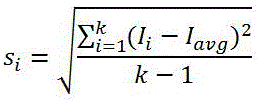
步骤4,若Si>Is,则对主点范围内的强度值进行排序,强度值最大的点即可认为是路面噪点,进行剔除,Is是标准差阈值。Step 4: If Si > I s , the intensity values within the main point range are sorted, and the point with the largest intensity value can be considered as a road noise point and removed. I s is the standard deviation threshold.
基于相同的构思还提出了一种车道线点云自动修补装置,包括至少一个处理器,以及与所述至少一个处理器通信连接的存储器;所述存储器存储有可被所述至少一个处理器执行的指令,所述指令被所述至少一个处理器执行,以使所述至少一个处理器能够执行上述任一项所述的一种车道线点云自动修补方法。Based on the same concept, a lane line point cloud automatic patching device is also proposed, including at least one processor and a memory communicatively connected to the at least one processor; the memory stores instructions executable by the at least one processor, and the instructions are executed by the at least one processor so that the at least one processor can execute any of the above-mentioned lane line point cloud automatic patching methods.
与现有技术相比,本发明的有益效果:Compared with the prior art, the present invention has the following beneficial effects:
本发明的方法根据当前截面的前一个截面第一个峰值区间点云强度的均值和后续截面第一个峰值区间点云强度的均值计算出缺失的车道线对应的补充点云强度均值,并以补充点云强度均值在缺失的车道线的位置补充点云强度,实现了缺失的车道线的修补。本发明针对高速路车道标线的缺失,给出了针对性的修补方案,该方案还可以推广到其他路段的车道标线修补,修补准确高效。The method of the present invention calculates the mean value of the supplementary point cloud intensity corresponding to the missing lane line based on the mean value of the point cloud intensity of the first peak interval of the previous section of the current section and the mean value of the point cloud intensity of the first peak interval of the subsequent section, and supplements the point cloud intensity at the position of the missing lane line with the supplementary point cloud intensity mean value, thereby repairing the missing lane line. The present invention provides a targeted repair scheme for the missing lane markings on highways, and the scheme can also be extended to the repair of lane markings on other sections, with accurate and efficient repair.
附图说明BRIEF DESCRIPTION OF THE DRAWINGS
图1为本发明实施例1中一种车道线点云自动提取方法的流程图;FIG1 is a flow chart of a method for automatically extracting lane point clouds in Embodiment 1 of the present invention;
图2为本发明实施例1中进行CSF布料滤波的流程图;FIG2 is a flow chart of performing CSF cloth filtering in Embodiment 1 of the present invention;
图3为本发明实施例1中利用k-d树进行邻域搜索的方法去噪的步骤流程图;FIG3 is a flowchart of the steps of denoising the method for performing neighborhood search using a k-d tree in Embodiment 1 of the present invention;
图4为本发明实施例3中截面的示意图;FIG4 is a schematic diagram of a cross section in Example 3 of the present invention;
图5为本发明实施例3中轨迹点至缺失标线中心宽度d的示意图;FIG5 is a schematic diagram of the width d from a track point to the center of a missing marking line in Example 3 of the present invention;
图6为本发明实施例3中一种完整的车道线点云自动修补方法的流程图。FIG6 is a flow chart of a complete lane line point cloud automatic repair method in Embodiment 3 of the present invention.
具体实施方式DETAILED DESCRIPTION
下面结合试验例及具体实施方式对本发明作进一步的详细描述。但不应将此理解为本发明上述主题的范围仅限于以下的实施例,凡基于本发明内容所实现的技术均属于本发明的范围。The present invention is further described in detail below in conjunction with test examples and specific implementation methods. However, this should not be understood as the scope of the above subject matter of the present invention being limited to the following embodiments, and all technologies realized based on the content of the present invention belong to the scope of the present invention.
实施例1Example 1
一种车道线点云自动提取方法,流程图如图1所示,包括以下步骤:A method for automatically extracting lane line point cloud, the flow chart of which is shown in FIG1, comprises the following steps:
S1,获取道路路面的激光点云数据。S1, obtaining laser point cloud data of the road surface.
利用车载激光设备对某条高速试点路段进行数据采集,包括左右幅主线路面都被采集。采集数据为涵盖点云强度值信息的激光点云数据,激光点云数据由若干激光点构成。对采集的高速路面激光点云数据进行属性选取,选取其中的基本属性值X、Y、Z、I,其中X、Y、Z代表点的三维坐标,I代表激光点的强度值(强度数据)。The vehicle-mounted laser equipment is used to collect data on a certain high-speed pilot road section, including the left and right main road surfaces. The collected data is laser point cloud data that contains point cloud intensity value information, and the laser point cloud data is composed of several laser points. The collected high-speed road surface laser point cloud data is attributed, and the basic attribute values X, Y, Z, and I are selected, where X, Y, and Z represent the three-dimensional coordinates of the point, and I represents the intensity value (intensity data) of the laser point.
其次,对激光点云数据进行预处理,包括梯度滤波、布料滤波和去噪。Secondly, the laser point cloud data is preprocessed, including gradient filtering, cloth filtering and denoising.
S2,采用梯度滤波方法对激光点云数据进行滤波,删除起伏变化大的非路面点云数据,得到点云粗提取数据。S2, using the gradient filtering method to filter the laser point cloud data, delete the non-road point cloud data with large fluctuations, and obtain the point cloud coarse extraction data.
利用梯度滤波进行点云粗提取,具体是指:对地面激光点的Z坐标进行标量,对激光点云数据进行k-d树三维空间索引,在主点范围内进行近邻搜索,获取主点M的高程梯度均值

其中,


通过梯度滤波删除了起伏变化大的非路面点云,得到点云粗提取数据。The non-road point cloud with large fluctuations is deleted through gradient filtering to obtain the rough extraction data of the point cloud.
S3,用布料滤波方法对点云粗提取数据进行滤波,得到点云精提取数据。S3, using the cloth filtering method to filter the rough extraction data of the point cloud to obtain the fine extraction data of the point cloud.
随后进行CSF布料滤波,进一步为准确提取道路路面点云数据进行数据上的筛选,进行CSF布料滤波的流程图如图2所述,具体步骤如下:Then, CSF cloth filtering is performed to further screen the data for accurate extraction of road surface point cloud data. The flowchart of CSF cloth filtering is shown in Figure 2. The specific steps are as follows:
步骤S301,设置滤波网格大小,格网越小模拟精度越高,计算时间越长,将梯度滤波后的点Pi进行CSF布料模拟,滤波网格大小可以自由拟定,格网设定的大小决定布料算法模拟地形的精度,优选的,格网大小设置为0.1,设定0.1计算时间不长且模拟精度好。设置高程最高点,高程最高点的高程值大于梯度滤波后的点云的高程值。Step S301, set the filter grid size. The smaller the grid, the higher the simulation accuracy and the longer the calculation time. Perform CSF cloth simulation on the point Pi after gradient filtering. The filter grid size can be freely set. The size of the grid setting determines the accuracy of the terrain simulation algorithm. Preferably, the grid size is set to 0.1. Setting 0.1 does not take long to calculate and has good simulation accuracy. Set the highest elevation point. The elevation value of the highest elevation point is greater than the elevation value of the point cloud after gradient filtering.
步骤S302,根据步骤S301中的网格大小设置布料模拟点(布料模拟粒子)和激光点,对模拟点和激光点进行水平面投影,寻找每个模拟点最邻近的激光点的高程hi。Step S302, setting cloth simulation points (cloth simulation particles) and laser points according to the grid size in step S301, performing horizontal plane projection on the simulation points and the laser points, and finding the elevation h i of the laser point closest to each simulation point.
步骤S303,将布料模拟粒子视为可移动对象,布料模拟粒子受到重力影响,在重力影响条件下判断布料模拟粒子的高度,当布料模拟粒子高度hv≤hi时,把布料模拟粒子的高度设置为hv并设置为不可移动点。Step S303, the cloth simulation particle is regarded as a movable object. The cloth simulation particle is affected by gravity. The height of the cloth simulation particle is determined under the influence of gravity. When the height of the cloth simulation particle h v ≤hi , the height of the cloth simulation particle is set to h v and set to an immovable point.
步骤S304,计算布料模拟粒子之间的内力作用,根据设置的布料刚性参数,计算其受到内部驱动因素影响所产生的位移

式中,当粒子处于移动状态,b值为1,反之为0,
步骤S305,重复步骤3和步骤4进行计算,直到迭代次数达到设置的最大迭代次数。粒子在模拟过程中需要受到外力和内力的同时影响,外力即重力,内力即粒子之间的相互作用力。在粒子模拟过程中,步骤3模拟外力,步骤4模拟内力,直到所有粒子的最大高度变化足够小或者迭代次数到达预先设置值,则停止模拟。作为优选方案,本发明采用迭代次数作为停止模拟的条件,这里最大迭代次数设置为500,得到最终模拟布料粒子的高度,粒子的模拟受到外力(重力)和内力影响,两种力都会影响模拟粒子的高度。迭代次数越多,模拟越准确。Step S305, repeat step 3 and step 4 to calculate until the number of iterations reaches the set maximum number of iterations. Particles need to be affected by both external and internal forces during the simulation process. The external force is gravity, and the internal force is the interaction force between particles. During the particle simulation process, step 3 simulates the external force, and step 4 simulates the internal force until the maximum height change of all particles is small enough or the number of iterations reaches a preset value, then the simulation is stopped. As a preferred solution, the present invention uses the number of iterations as a condition for stopping the simulation. Here, the maximum number of iterations is set to 500 to obtain the final simulated height of the cloth particles. The simulation of the particles is affected by external forces (gravity) and internal forces, and both forces will affect the height of the simulated particles. The more iterations, the more accurate the simulation.
步骤S306,比较激光点与模拟点之间的距离差值,当差值小于或等于阈值时,对应的激光点标记为地面点,当差值大于阈值时,激光点则标记为非地面点,这里阈值设定为0.5米。Step S306, compare the distance difference between the laser point and the simulation point. When the difference is less than or equal to the threshold, the corresponding laser point is marked as a ground point. When the difference is greater than the threshold, the laser point is marked as a non-ground point. Here, the threshold is set to 0.5 meters.
通过步骤S301- S306,得到所有处理完成的道路路面的点云精提取数据。Through steps S301 - S306 , the point cloud precise extraction data of all processed road surfaces are obtained.
S4,将点云精提取数据依次通过暗通道去噪和k-d树搜索的邻域去噪,得到优化后的车道线点云数据。S4, the point cloud extracted data is subjected to dark channel denoising and k-d tree search neighborhood denoising in turn to obtain the optimized lane line point cloud data.
高速公路路面经过长时间的高负荷运行后,路面的沥青材质受到较长时间的挤压磨损,表面沥青在车载激光扫描后得到的反射值与未磨损路面的反射值存在一定差异,将这种挤压受损路面视为有噪声,进行去噪处理。将路面强度数据基于暗通道去雾处理,纠正沥青路面强度部分失真的情况。将带有噪声反射的强度数据I(x)视作雾,暗通道去雾模型如下:After a long period of high-load operation, the asphalt material of the highway pavement is squeezed and worn for a long time. The reflection value of the surface asphalt obtained after the vehicle-mounted laser scanning is different from the reflection value of the unworn pavement. This squeezed and damaged pavement is regarded as noisy and denoised. The pavement intensity data is defogged based on the dark channel to correct the partial distortion of the asphalt pavement intensity. The intensity data I(x) with noise reflection is regarded as fog, and the dark channel defogging model is as follows:

式中,J(x)为无雾数据,将路面点云噪声视作雾,修正后的无雾点强度值J(x)即为去除噪声后的路面点云,t(x)为透射率,其中A为大气光强度,一般说来透射率值越大,图像有雾程度就越明显。这里透射率可根据点云强度分布频率p得到,即In the formula, J(x) is the fog-free data, and the road point cloud noise is regarded as fog. The corrected fog-free point intensity value J(x) is the road point cloud after noise removal, and t(x) is the transmittance, where A is the atmospheric light intensity. Generally speaking, the larger the transmittance value, the more obvious the image fog. Here, the transmittance can be obtained according to the point cloud intensity distribution frequency p, that is,

当透射率t(x)无限逼近于0时,认为图像为无雾图像。但当t(x)=0时,会出现图像色彩过饱和情况,因此设定t(x)一个最小临界值t0=0.1,让图像更加接近于自然光条件下效果。因此,修正后的无雾点强度J(x)值公式如下:When the transmittance t(x) approaches 0 infinitely, the image is considered to be a fog-free image. However, when t(x)=0, the image color will be oversaturated, so a minimum critical value t 0 =0.1 is set for t(x) to make the image closer to the effect under natural light conditions. Therefore, the formula for the corrected fog-free point intensity J(x) value is as follows:

式中,A为大气光强度,t(x)为透射率,t0是透射率最小临界值,I(x)是带有噪声反射的强度数据。将带有噪声反射的强度数据I(x)通过上式进行计算,得到修正后的无雾点强度值J(x)即完成了暗通道点云滤波。In the formula, A is the atmospheric light intensity, t(x) is the transmittance, t0 is the minimum critical value of transmittance, and I(x) is the intensity data with noise reflection. The intensity data with noise reflection I(x) is calculated by the above formula to obtain the corrected fog-free point intensity value J(x), thus completing the dark channel point cloud filtering.
基于暗通道点云滤波完成后,仍然存在个别不规则的白色亮点,其强度值明显高于周围点强度大小。因此,利用k-d树进行邻域搜索,同时计算激光点的强度标准差,若标准差大于标准差阈值Is,则认为该主点范围内存在白色强噪点,对噪点进行剔除。标准差阈值Is的范围根据点云数据本身确定,不是一个通用固定值,不同型号的车载激光设备对同一个地物进行扫描,点的强度值是不一样的。利用k-d树进行邻域搜索的方法去噪的步骤流程图如图3所示,此处是经过梯度滤波、CSF滤波、暗通道去噪之后对剩下的点云进行的个别独立点去噪,具体步骤如下:After the dark channel point cloud filtering is completed, there are still some irregular white bright spots, whose intensity values are significantly higher than the intensity of the surrounding points. Therefore, the kd tree is used to perform neighborhood search, and the intensity standard deviation of the laser point is calculated at the same time. If the standard deviation is greater than the standard deviation threshold Is , it is considered that there are strong white noise points within the main point range, and the noise points are removed. The range of the standard deviation threshold Is is determined according to the point cloud data itself, and it is not a universal fixed value. Different models of vehicle-mounted laser equipment scan the same object, and the intensity values of the points are different. The denoising steps of the method of neighborhood search using the kd tree are shown in Figure 3. Here, individual independent points of the remaining point cloud are denoised after gradient filtering, CSF filtering, and dark channel denoising. The specific steps are as follows:
步骤1,利用k-d树进行邻域搜索,对所有搜索到的邻域点集进行点强度均值Iavg进行计算,计算公式为:Step 1: Use the kd tree to perform neighborhood search and calculate the point intensity mean I avg of all searched neighborhood point sets. The calculation formula is:

其中,Ii是激光点云数据中某邻域内部的不同激光点强度值,i是激光点的序号,k是作为某邻域内部搜索范围内激光点的数量。Among them, I i is the intensity value of different laser points within a neighborhood in the laser point cloud data, i is the serial number of the laser point, and k is the number of laser points within the search range within a neighborhood.
步骤2,进行邻域范围内点集方差

步骤3,进行邻域范围内点集标准差Si计算:Step 3, calculate the standard deviation Si of the point set within the neighborhood:

步骤4,若Si>Is,则对邻域范围内点集的强度值进行排序,强度值最大的一个点即可认为是路面噪点,进行剔除。Step 4: If Si > Is , the intensity values of the point set within the neighborhood are sorted, and the point with the largest intensity value can be considered as a road noise point and removed.
孤立噪点的强度值是明显大于周围点的,如果只做排序,是无法找出孤立噪点的,因此,需要计算标准差找到主点与临近点的标差值,通过标准差阈值Is对标准差Si进行过滤筛选,然后再进行排序,就排除了孤立噪点。The intensity value of isolated noise points is obviously greater than that of surrounding points. If we only do sorting, we cannot find isolated noise points. Therefore, we need to calculate the standard deviation to find the standard deviation value between the main point and the adjacent points, filter the standard deviation Si by the standard deviation threshold Is , and then sort to exclude isolated noise points.
路面点云异常噪点剔除后,就完成了点云精提取数据的去噪等预处理步骤,得到优化后的车道点云数据。上述方法对获取的道路路面的激光点云数据依次进行梯度滤波、布料滤波、暗通道去噪和k-d树搜索的邻域去噪,使得提取的车道线点云数据更加准确,提取出的车道线能准确提供道路车道级位置信息,自动化程度高,提供信息准确稳定可靠。After the abnormal noise points of the road surface point cloud are removed, the preprocessing steps such as denoising of the point cloud extracted data are completed, and the optimized lane point cloud data is obtained. The above method sequentially performs gradient filtering, cloth filtering, dark channel denoising and k-d tree search neighborhood denoising on the acquired laser point cloud data of the road surface, making the extracted lane line point cloud data more accurate. The extracted lane line can accurately provide the road lane-level position information, with a high degree of automation, and the information provided is accurate, stable and reliable.
实施例3Example 3
按照实施例1或实施例2的方法就实现了对点云数据的滤波和去噪处理,得到优化后的车道点云数据,使得优化后的车道点云数据质量更高,有助于后续车道线的高精度提取。According to the method of Example 1 or Example 2, filtering and denoising of the point cloud data are implemented to obtain optimized lane point cloud data, so that the optimized lane point cloud data has higher quality, which is helpful for the subsequent high-precision extraction of lane lines.
除了点云数据本身的预处理以外,还需要克服车道线被遮挡的问题。由于车载激光在路面扫描时,路面点容易受到车辆遮挡影响,导致路面点云存在局部缺失,因此,将pos轨迹点结合道路形态进行局部线性标线点云弥补:In addition to the preprocessing of the point cloud data itself, it is also necessary to overcome the problem of lane line occlusion. When the vehicle-mounted laser scans the road surface, the road surface points are easily affected by the vehicle occlusion, resulting in partial missing of the road surface point cloud. Therefore, the POS trajectory points are combined with the road shape to make up for the local linear marking point cloud:
利用行车轨迹点从初始点开始往前跟踪,沿着扫描方向进行截面获取,由于高速公路存在整体式路面和分离式路面,这里都计算高速道路的半幅路面。The driving trajectory points are used to track forward from the initial point and obtain cross-sections along the scanning direction. Since there are integral pavements and separated pavements on highways, half of the highway pavement is calculated here.
在车载激光扫描过程中,车载轨迹点会自动生成。根据轨迹点生成轨迹线的方程为V(s)=[x(s),y(s),z(s)],其中x(s),y(s),z(s)为组成轨迹线的各坐标点信息,s为归一化弧长,V(s) 指车载激光所经过的轨迹线,它是由各个轨迹点集合组成的轨迹点的集合表达。During the vehicle-mounted laser scanning process, the vehicle-mounted trajectory points are automatically generated. The equation for generating the trajectory line based on the trajectory points is V(s)=[x(s),y(s),z(s)], where x(s),y(s),z(s) are the coordinate information of each point that composes the trajectory line, s is the normalized arc length, and V(s) refers to the trajectory line that the vehicle-mounted laser passes through, which is a set expression of the trajectory points composed of each set of trajectory points.
在车载激光扫描过程中发现,标线的反射强度明显高于沥青路面,因此定义轨迹点Sk截面位置Section(k),计算当前截面Section(k)的整个强度值区间的峰值区域,得到标线信息。During the on-board laser scanning process, it was found that the reflection intensity of the marking was significantly higher than that of the asphalt pavement. Therefore, the section position Section(k) of the trajectory point Sk was defined, and the peak area of the entire intensity value interval of the current section Section(k) was calculated to obtain the marking information.
首先,计算截面Section(k)。截面定义为轨迹线延伸方向的法平面所在位置,据所在的轨迹点Sk的轨迹向量

式中,


这里定义
受到路面行车影响,车道线被遮挡,激光扫描无法获取局部空间点云特征。一般情况中,认为在同等距离的扫描条件下,同类构造物的车载激光的反射强度基本保持不变。因此,通过计算截面点云强度分布位置判别空缺长实线标线可能出现变化的情况,这里以靠近中央隔离带的车道长标线局部缺失为例。Affected by the driving on the road, the lane line is blocked and the laser scanning cannot obtain the local spatial point cloud features. In general, it is believed that under the same scanning distance, the reflection intensity of the vehicle-mounted laser of the same structure remains basically unchanged. Therefore, by calculating the intensity distribution position of the cross-sectional point cloud, the situation where the vacant long solid line marking may change is judged. Here, the partial missing of the lane long marking near the central isolation belt is taken as an example.
需要说明的是,本专利修补车道线点云的方法适用于高速公路左右幅路面的长实形标线,后续公式同样适用于靠近主车道与应急车道之间的长实线标线点云修补。由于车载激光进行扫描作业时,车辆绝大部分按照车道行驶,因此基本不会出现车道1与车道2之间的短实形标线被车辆遮挡而扫描不到的情况,以下公式、方法仅用于道路左右幅路面两侧的长实形标线修补。It should be noted that the method of repairing lane line point cloud in this patent is applicable to the long solid line markings on the left and right sides of the highway, and the subsequent formula is also applicable to the point cloud repair of the long solid line markings between the main lane and the emergency lane. Since most vehicles drive according to the lanes when the vehicle-mounted laser performs scanning operations, it is basically impossible for the short solid line markings between lane 1 and lane 2 to be blocked by vehicles and cannot be scanned. The following formulas and methods are only used for the repair of long solid line markings on both sides of the left and right sides of the road.
步骤1,当截面获取点云出现明显点云空缺,开始计算。在该位置处,行车轨迹点对应截面的点云发生明显变化,即截面第一个点云强度峰值位置发生显著变化,对前一个轨迹点Sp截面第一个峰值区间点云强度进行读取并求取均值I1:Step 1: When there is an obvious point cloud gap in the cross-section point cloud, start the calculation. At this position, the point cloud of the cross-section corresponding to the driving trajectory point changes significantly, that is, the position of the first point cloud intensity peak of the cross-section changes significantly. The point cloud intensity of the first peak interval of the previous trajectory point Sp cross-section is read and the average value I 1 is calculated:

式中,kp代表轨迹点Sp所在截面第一个点云峰值区间点云个数。Where kp represents the number of point clouds in the first point cloud peak interval of the section where the trajectory point Sp is located.
步骤2,行车轨迹点Sq所在截面第一次峰值位置恢复正常时,即当前截面已经不存在点云缺失,记录当前截面第一个峰值区间点云强度并求取均值I2:Step 2: When the first peak position of the section where the driving trajectory point Sq is located returns to normal, that is, there is no point cloud missing in the current section, record the point cloud intensity of the first peak interval of the current section and calculate the average value I 2 :

式中,kq代表轨迹点Sq所在截面第一个点云峰值区间点云个数。Where kq represents the number of point clouds in the first point cloud peak interval of the section where the trajectory point Sq is located.
步骤3,第一个点云强度峰值位置发生变化的该区间为轨迹线上轨迹点Sp到轨迹点Sq的区间。缺失标线视为与轨迹线平行,通过轨迹点Sp和Sq所对应的截面位置就可以得到当前截面下缺失标线两端的截面中心位置,对两个缺失标线两端的截面中心位置进行连接即可得到缺失标线的中心线,由于标线宽度是固定值,就可根据缺失标线的中心线和标线宽度修补到缺失的标线点云。Step 3: The interval where the first point cloud intensity peak position changes is the interval from track point Sp to track point Sq on the track line. The missing marking line is considered to be parallel to the track line. The section positions corresponding to track points Sp and Sq can be used to obtain the section center positions at both ends of the missing marking line under the current section. The center line of the missing marking line can be obtained by connecting the section center positions at both ends of the two missing marking lines. Since the marking line width is a fixed value, the missing marking line point cloud can be repaired according to the center line and marking line width of the missing marking line.
轨迹点至缺失标线中心宽度d所表示的距离如图5所示,轨迹线上轨迹点Sp到轨迹点Sq的区间可以认为是直线行驶,缺失标线的中心位置Fm(xm,ym,zm)连接构成的缺失标线的中心线视为与轨迹点Sp到轨迹点Sq之间的轨迹线保持平行,缺失标线中心至轨迹点的宽度为固定长度值
其中d的长度值取激光正好扫描到左侧第一根车道线点云的峰值位置中心与车载激光轨迹点Sp的距离:The length of d is the distance between the peak position center of the point cloud of the first lane line on the left and the vehicle-mounted laser trajectory point Sp :

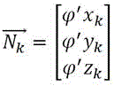
式中, (xp,yp)表示轨迹点Sp坐标,当前缺失标线的中心位置Fm与当前车载轨迹点Sq可以认为位于统一高程位置,因此可以认为zm=zp,因此该车载轨迹点的法平面方程可变成法线方程:Where ( xp , yp ) represents the coordinates of the track point Sp . The center position Fm of the current missing marking and the current vehicle track point Sq can be considered to be at the same elevation, so zm = zp . Therefore, the normal plane equation of the vehicle track point can be transformed into the normal line equation:

式中,
利用前述步骤1和2获取的均值I1与均值I2的求得缺失标线修补范围内的弥补点云强度Im,对缺失的标线进行点云修补,弥补点云强度Im的计算公式为:The mean values I1 and I2 obtained in the above steps 1 and 2 are used to obtain the compensation point cloud intensity I m within the missing marking repair range, and the missing marking is repaired by point cloud. The calculation formula of the compensation point cloud intensity I m is:

这里车道长实线标线部分区间丢失弥补不限于中央隔离带位置标线弥补,同样适用于行车道与应急停车道间的长实线车道线点云弥补。Here, the compensation for the missing section of the long solid lane marking is not limited to the compensation for the central isolation zone position marking, but is also applicable to the point cloud compensation for the long solid lane line between the driving lane and the emergency parking lane.
对截面强度峰值区间P、非峰值区间Q长度Lengthp、LengthQ进行计算(以双向4车道高速为例,本专利方法不仅限于高速公路车道数量,对其他路面仍然具备适用性),若长度Lengthp、LengthQ满足一下条件1或者条件2(条件1见附图截面1所示,条件2见截面2所示),则判定截面有长实形标线:Calculate the lengths Length p and Length Q of the peak strength interval P and the non-peak strength interval Q of the cross section (taking a two-way 4-lane highway as an example, this patent method is not limited to the number of lanes on the highway, and is still applicable to other road surfaces). If the lengths Length p and Length Q meet the following conditions 1 or 2 (condition 1 is shown in section 1 of the attached figure, and condition 2 is shown in section 2), it is determined that the cross section has a long solid marking line:


式中,(xk1,yk1)、(xk2,yk2)分别表示截面第一个峰值区间起止点坐标,(xk3,yk3)、(xk4,yk4)分别表示截面第二个峰值区间起止点坐标。具体来说:In the formula, (x k1 ,y k1 ) and (x k2 ,y k2 ) represent the coordinates of the starting and ending points of the first peak interval of the cross section, and (x k3 ,y k3 ) and (x k4 ,y k4 ) represent the coordinates of the starting and ending points of the second peak interval of the cross section. Specifically:
1)当截面Section(k)存在2个点云强度峰值区间P,且非峰值区间Q长度满足条件2,则该条截面上存在2条长实形标线,无其他类型标线,情况见附图4截面2所示;1) When there are two point cloud intensity peak intervals P in section Section(k), and the length of the non-peak interval Q meets condition 2, there are two long solid marking lines on the section, and no other types of marking lines, as shown in section 2 in Figure 4;
2)当截面Section(k)存在3个点云强度峰值区间P,且非峰值区间Q长度满足条件1,则该条截面上存在2条长实形标线及1条短实形标线,无其他类型标线,情况见附图4截面1所示;2) When there are three point cloud intensity peak intervals P in section Section(k), and the length of the non-peak interval Q meets condition 1, there are two long solid marking lines and one short solid marking line on the section, and no other types of marking lines, as shown in section 1 in Figure 4;
3)当截面Section(k)存在4个及以上点云强度峰值区间P,且第一个峰值区间长度与最后一个区间峰值长度中的间距满足LengthQ2,说明该条截面上存在不同种类标线特征,两端为实线标线,中间位置判定当前位置有车道导向箭头等其他类型标线,情况见附图4截面3所示;3) When there are 4 or more point cloud intensity peak intervals P in section Section(k), and the distance between the length of the first peak interval and the length of the last peak interval satisfies Length Q2 , it means that there are different types of marking features on the section, with solid markings at both ends and other types of markings such as lane guide arrows at the middle position. The situation is shown in Section 3 of Figure 4;
对所有截面峰值位置进行统计,保留情况1、情况2中的峰值区间截面上的点集,保留情况3中第一个和最后一个峰值区间截面上的点集,即可得到所有的车道线位置。图6是本发明一种完整的车道线点云自动修补方法的流程图。By counting the peak positions of all sections, retaining the point sets on the peak interval sections in cases 1 and 2, and retaining the point sets on the first and last peak interval sections in case 3, all lane line positions can be obtained. FIG6 is a flow chart of a complete lane line point cloud automatic repair method of the present invention.
以上显示和描述了本发明的基本原理和主要特征及本发明的优点,对于本领域技术人员而言,显然在不背离本发明的精神或基本特征的情况下,能够以其他的具体形式实现本发明。因此,无论从哪一点来看,均应将实施例看作是示范性的,而且是非限制性的,本发明的范围由所附权利要求而不是上述说明限定,因此旨在将落在权利要求的等同要件的含义和范围内的所有变化囊括在本发明内。不应将权利要求中的任何附图标记视为限制所涉及的权利要求。The above shows and describes the basic principles and main features of the present invention and the advantages of the present invention. It is obvious to those skilled in the art that the present invention can be implemented in other specific forms without departing from the spirit or basic features of the present invention. Therefore, no matter from which point of view, the embodiments should be regarded as exemplary and non-restrictive. The scope of the present invention is limited by the attached claims rather than the above description, and it is intended that all changes falling within the meaning and scope of the equivalent elements of the claims are included in the present invention. Any figure mark in the claims should not be regarded as limiting the claims involved.
此外,应当理解,虽然本说明书按照实施方式加以描述,但并非实施方式仅包含一个独立的技术方案,说明书的这种叙述方式仅仅是为清楚起见,本领域技术人员应当将说明书作为一个整体,实施例中的技术方案也可以经适当组合,形成本领域技术人员可以理解的其他实施方式。In addition, it should be understood that although the present specification is described according to the implementation mode, the implementation mode does not only include an independent technical solution. This narrative method of the specification is only for the sake of clarity. Those skilled in the art should regard the specification as a whole. The technical solutions in the embodiments can also be appropriately combined to form other implementation modes that can be understood by those skilled in the art.
Claims (10)


Priority Applications (1)
| Application Number | Priority Date | Filing Date | Title |
|---|---|---|---|
| CN202310490354.8A CN116188334B (en) | 2023-05-04 | 2023-05-04 | A method and device for automatically repairing lane line point clouds |
Applications Claiming Priority (1)
| Application Number | Priority Date | Filing Date | Title |
|---|---|---|---|
| CN202310490354.8A CN116188334B (en) | 2023-05-04 | 2023-05-04 | A method and device for automatically repairing lane line point clouds |
Publications (2)
| Publication Number | Publication Date |
|---|---|
| CN116188334A true CN116188334A (en) | 2023-05-30 |
| CN116188334B CN116188334B (en) | 2023-07-18 |
Family
ID=86440691
Family Applications (1)
| Application Number | Title | Priority Date | Filing Date |
|---|---|---|---|
| CN202310490354.8A Active CN116188334B (en) | 2023-05-04 | 2023-05-04 | A method and device for automatically repairing lane line point clouds |
Country Status (1)
| Country | Link |
|---|---|
| CN (1) | CN116188334B (en) |
Cited By (1)
| Publication number | Priority date | Publication date | Assignee | Title |
|---|---|---|---|---|
| CN116699644A (en) * | 2023-08-07 | 2023-09-05 | 四川华腾公路试验检测有限责任公司 | Marking reliability assessment method based on three-dimensional laser radar |
Citations (14)
| Publication number | Priority date | Publication date | Assignee | Title |
|---|---|---|---|---|
| CN107679458A (en) * | 2017-09-07 | 2018-02-09 | 中国地质大学(武汉) | The extracting method of roadmarking in a kind of road color laser point cloud based on K Means |
| CN109165549A (en) * | 2018-07-09 | 2019-01-08 | 厦门大学 | Road markings acquisition methods, terminal device and device based on three dimensional point cloud |
| WO2019170012A1 (en) * | 2018-03-09 | 2019-09-12 | 腾讯科技(深圳)有限公司 | Traffic lane line data processing method and apparatus, computer device, and storage medium |
| CN110532963A (en) * | 2019-08-30 | 2019-12-03 | 扆亮海 | A kind of accurate extracting method of roadmarking of mobile lidar point cloud driving |
| CN110647798A (en) * | 2019-08-05 | 2020-01-03 | 中国铁路设计集团有限公司 | Automatic track center line detection method based on vehicle-mounted mobile laser point cloud |
| US20200142067A1 (en) * | 2018-11-01 | 2020-05-07 | Automotive Research & Testing Center | Lane stripe detecting method based on three-dimensional lidar and system thereof |
| US20200363202A1 (en) * | 2019-05-17 | 2020-11-19 | Hexagon Technology Center Gmbh | Fully automatic position and alignment determination method for a terrestrial laser scanner and method for ascertaining the suitability of a position for a deployment for surveying |
| CN111968253A (en) * | 2020-07-09 | 2020-11-20 | 北京工业大学 | Point cloud data-based road surface extraction method and system |
| CN112561944A (en) * | 2020-11-27 | 2021-03-26 | 中央财经大学 | Lane line extraction method based on vehicle-mounted laser point cloud |
| CN113280798A (en) * | 2021-07-20 | 2021-08-20 | 四川省公路规划勘察设计研究院有限公司 | Geometric correction method for vehicle-mounted scanning point cloud under tunnel GNSS rejection environment |
| CN114092658A (en) * | 2021-11-19 | 2022-02-25 | 四川易利数字城市科技有限公司 | High-precision map construction method |
| CN114445565A (en) * | 2020-11-06 | 2022-05-06 | 北京嘀嘀无限科技发展有限公司 | Data processing method, apparatus, electronic device and computer readable medium |
| CN114581492A (en) * | 2022-05-07 | 2022-06-03 | 成都理工大学 | Vehicle-mounted laser radar point cloud non-rigid registration method fusing road multi-feature |
| CN115187944A (en) * | 2022-06-29 | 2022-10-14 | 合众新能源汽车有限公司 | Lane line detection method and device |
-
2023
- 2023-05-04 CN CN202310490354.8A patent/CN116188334B/en active Active
Patent Citations (14)
| Publication number | Priority date | Publication date | Assignee | Title |
|---|---|---|---|---|
| CN107679458A (en) * | 2017-09-07 | 2018-02-09 | 中国地质大学(武汉) | The extracting method of roadmarking in a kind of road color laser point cloud based on K Means |
| WO2019170012A1 (en) * | 2018-03-09 | 2019-09-12 | 腾讯科技(深圳)有限公司 | Traffic lane line data processing method and apparatus, computer device, and storage medium |
| CN109165549A (en) * | 2018-07-09 | 2019-01-08 | 厦门大学 | Road markings acquisition methods, terminal device and device based on three dimensional point cloud |
| US20200142067A1 (en) * | 2018-11-01 | 2020-05-07 | Automotive Research & Testing Center | Lane stripe detecting method based on three-dimensional lidar and system thereof |
| US20200363202A1 (en) * | 2019-05-17 | 2020-11-19 | Hexagon Technology Center Gmbh | Fully automatic position and alignment determination method for a terrestrial laser scanner and method for ascertaining the suitability of a position for a deployment for surveying |
| CN110647798A (en) * | 2019-08-05 | 2020-01-03 | 中国铁路设计集团有限公司 | Automatic track center line detection method based on vehicle-mounted mobile laser point cloud |
| CN110532963A (en) * | 2019-08-30 | 2019-12-03 | 扆亮海 | A kind of accurate extracting method of roadmarking of mobile lidar point cloud driving |
| CN111968253A (en) * | 2020-07-09 | 2020-11-20 | 北京工业大学 | Point cloud data-based road surface extraction method and system |
| CN114445565A (en) * | 2020-11-06 | 2022-05-06 | 北京嘀嘀无限科技发展有限公司 | Data processing method, apparatus, electronic device and computer readable medium |
| CN112561944A (en) * | 2020-11-27 | 2021-03-26 | 中央财经大学 | Lane line extraction method based on vehicle-mounted laser point cloud |
| CN113280798A (en) * | 2021-07-20 | 2021-08-20 | 四川省公路规划勘察设计研究院有限公司 | Geometric correction method for vehicle-mounted scanning point cloud under tunnel GNSS rejection environment |
| CN114092658A (en) * | 2021-11-19 | 2022-02-25 | 四川易利数字城市科技有限公司 | High-precision map construction method |
| CN114581492A (en) * | 2022-05-07 | 2022-06-03 | 成都理工大学 | Vehicle-mounted laser radar point cloud non-rigid registration method fusing road multi-feature |
| CN115187944A (en) * | 2022-06-29 | 2022-10-14 | 合众新能源汽车有限公司 | Lane line detection method and device |
Non-Patent Citations (6)
| Title |
|---|
| NOVEL CERTAD等: "Road Markings Segmentation from LIDAR Point Clouds using Reflectivity Information", 《ARXIV》, pages 1 - 6 * |
| 刘霜辰 等: "激光点云建模在公路资产管理中的应用", 《公路》, vol. 68, no. 1, pages 230 - 234 * |
| 吴愚: "多模态融合感知技术研究与设计", 《中国优秀硕士学位论文全文数据库 信息科技辑》, no. 1, pages 138 - 2624 * |
| 姚连璧 等: "车载激光点云的道路标线提取及语义关联", 《测绘学报》, no. 4, pages 480 - 488 * |
| 李会宾: "基于激光点云的道路边界检测和标线识别方法的研究与实现", 《中国优秀硕士学位论文全文数据库 工程科技Ⅱ辑》, no. 4, pages 035 - 198 * |
| 甘能: "基于道路整体信息的激光雷达路沿识别算法研究", 《中国优秀硕士学位论文全文数据库 工程科技Ⅱ辑》, no. 1, pages 035 - 379 * |
Cited By (2)
| Publication number | Priority date | Publication date | Assignee | Title |
|---|---|---|---|---|
| CN116699644A (en) * | 2023-08-07 | 2023-09-05 | 四川华腾公路试验检测有限责任公司 | Marking reliability assessment method based on three-dimensional laser radar |
| CN116699644B (en) * | 2023-08-07 | 2023-10-27 | 四川华腾公路试验检测有限责任公司 | Marking reliability assessment method based on three-dimensional laser radar |
Also Published As
| Publication number | Publication date |
|---|---|
| CN116188334B (en) | 2023-07-18 |
Similar Documents
| Publication | Publication Date | Title |
|---|---|---|
| CN112200171B (en) | An extraction method of road point cloud based on scan line | |
| CN111192284B (en) | A vehicle laser point cloud segmentation method and system | |
| CN109165549B (en) | Road sign acquisition method, terminal equipment and device based on 3D point cloud data | |
| CN111079611B (en) | Automatic extraction method for road surface and marking line thereof | |
| CN114488073A (en) | Method for processing point cloud data acquired by laser radar | |
| CN105701449A (en) | Method and device for detecting lane lines on road surface | |
| CN114299247B (en) | Road traffic signs and markings rapid detection and troubleshooting methods | |
| CN112561944A (en) | Lane line extraction method based on vehicle-mounted laser point cloud | |
| CN110390256B (en) | Asphalt pavement crack extraction method | |
| CN115690773A (en) | DEM partitioning and rebuilding method, computing device and storage medium | |
| CN113920483A (en) | Method and device for classifying objects in road point cloud, electronic equipment and storage medium | |
| CN109870458B (en) | Pavement crack detection and classification method based on three-dimensional laser sensor and bounding box | |
| CN116188334A (en) | A method and device for automatically repairing lane line point clouds | |
| CN103679121A (en) | Method and system for detecting roadside using visual difference image | |
| CN112435336B (en) | Curve type identification method and device, electronic equipment and storage medium | |
| CN114170579B (en) | Road edge detection method and device and automobile | |
| CN117073664A (en) | A method for constructing road topography in open-pit mines | |
| JP2021018604A (en) | Image processing apparatus | |
| Chang et al. | The implementation of semi-automated road surface markings extraction schemes utilizing mobile laser scanned point clouds for HD maps production | |
| CN114740494A (en) | A multi-line lidar road boundary line extraction method | |
| CN118015132B (en) | Method and device for processing vehicle driving data and storage medium | |
| US12449274B2 (en) | Method and apparatus for generating map data, and non-transitory computer-readable storage medium | |
| CN116704446B (en) | Real-time detection method and system for foreign matters on airport runway pavement | |
| CN115390064B (en) | Method and related equipment for determining travelable area based on millimeter wave radar | |
| CN116071726A (en) | A road inspection system and method based on edge computing |
Legal Events
| Date | Code | Title | Description |
|---|---|---|---|
| PB01 | Publication | ||
| PB01 | Publication | ||
| SE01 | Entry into force of request for substantive examination | ||
| SE01 | Entry into force of request for substantive examination | ||
| GR01 | Patent grant | ||
| GR01 | Patent grant |