CN116139957A - A self-driven microfluidic biochip with stable detection and its application - Google Patents
A self-driven microfluidic biochip with stable detection and its application Download PDFInfo
- Publication number
- CN116139957A CN116139957A CN202310374318.5A CN202310374318A CN116139957A CN 116139957 A CN116139957 A CN 116139957A CN 202310374318 A CN202310374318 A CN 202310374318A CN 116139957 A CN116139957 A CN 116139957A
- Authority
- CN
- China
- Prior art keywords
- hydrophobic
- self
- microfluidic channel
- microfluidic
- hydrophobic microfluidic
- Prior art date
- Legal status (The legal status is an assumption and is not a legal conclusion. Google has not performed a legal analysis and makes no representation as to the accuracy of the status listed.)
- Pending
Links
Images


Classifications
-
- G—PHYSICS
- G01—MEASURING; TESTING
- G01N—INVESTIGATING OR ANALYSING MATERIALS BY DETERMINING THEIR CHEMICAL OR PHYSICAL PROPERTIES
- G01N21/00—Investigating or analysing materials by the use of optical means, i.e. using sub-millimetre waves, infrared, visible or ultraviolet light
- G01N21/75—Systems in which material is subjected to a chemical reaction, the progress or the result of the reaction being investigated
-
- B—PERFORMING OPERATIONS; TRANSPORTING
- B01—PHYSICAL OR CHEMICAL PROCESSES OR APPARATUS IN GENERAL
- B01L—CHEMICAL OR PHYSICAL LABORATORY APPARATUS FOR GENERAL USE
- B01L3/00—Containers or dishes for laboratory use, e.g. laboratory glassware; Droppers
- B01L3/50—Containers for the purpose of retaining a material to be analysed, e.g. test tubes
- B01L3/502—Containers for the purpose of retaining a material to be analysed, e.g. test tubes with fluid transport, e.g. in multi-compartment structures
- B01L3/5027—Containers for the purpose of retaining a material to be analysed, e.g. test tubes with fluid transport, e.g. in multi-compartment structures by integrated microfluidic structures, i.e. dimensions of channels and chambers are such that surface tension forces are important, e.g. lab-on-a-chip
- B01L3/50273—Containers for the purpose of retaining a material to be analysed, e.g. test tubes with fluid transport, e.g. in multi-compartment structures by integrated microfluidic structures, i.e. dimensions of channels and chambers are such that surface tension forces are important, e.g. lab-on-a-chip characterised by the means or forces applied to move the fluids
-
- B—PERFORMING OPERATIONS; TRANSPORTING
- B01—PHYSICAL OR CHEMICAL PROCESSES OR APPARATUS IN GENERAL
- B01L—CHEMICAL OR PHYSICAL LABORATORY APPARATUS FOR GENERAL USE
- B01L2300/00—Additional constructional details
- B01L2300/08—Geometry, shape and general structure
- B01L2300/0896—Nanoscaled
-
- B—PERFORMING OPERATIONS; TRANSPORTING
- B01—PHYSICAL OR CHEMICAL PROCESSES OR APPARATUS IN GENERAL
- B01L—CHEMICAL OR PHYSICAL LABORATORY APPARATUS FOR GENERAL USE
- B01L2300/00—Additional constructional details
- B01L2300/16—Surface properties and coatings
- B01L2300/161—Control and use of surface tension forces, e.g. hydrophobic, hydrophilic
-
- B—PERFORMING OPERATIONS; TRANSPORTING
- B01—PHYSICAL OR CHEMICAL PROCESSES OR APPARATUS IN GENERAL
- B01L—CHEMICAL OR PHYSICAL LABORATORY APPARATUS FOR GENERAL USE
- B01L2400/00—Moving or stopping fluids
- B01L2400/04—Moving fluids with specific forces or mechanical means
- B01L2400/0403—Moving fluids with specific forces or mechanical means specific forces
-
- B—PERFORMING OPERATIONS; TRANSPORTING
- B01—PHYSICAL OR CHEMICAL PROCESSES OR APPARATUS IN GENERAL
- B01L—CHEMICAL OR PHYSICAL LABORATORY APPARATUS FOR GENERAL USE
- B01L2400/00—Moving or stopping fluids
- B01L2400/08—Regulating or influencing the flow resistance
- B01L2400/084—Passive control of flow resistance
- B01L2400/088—Passive control of flow resistance by specific surface properties
-
- Y—GENERAL TAGGING OF NEW TECHNOLOGICAL DEVELOPMENTS; GENERAL TAGGING OF CROSS-SECTIONAL TECHNOLOGIES SPANNING OVER SEVERAL SECTIONS OF THE IPC; TECHNICAL SUBJECTS COVERED BY FORMER USPC CROSS-REFERENCE ART COLLECTIONS [XRACs] AND DIGESTS
- Y02—TECHNOLOGIES OR APPLICATIONS FOR MITIGATION OR ADAPTATION AGAINST CLIMATE CHANGE
- Y02A—TECHNOLOGIES FOR ADAPTATION TO CLIMATE CHANGE
- Y02A50/00—TECHNOLOGIES FOR ADAPTATION TO CLIMATE CHANGE in human health protection, e.g. against extreme weather
- Y02A50/30—Against vector-borne diseases, e.g. mosquito-borne, fly-borne, tick-borne or waterborne diseases whose impact is exacerbated by climate change
Landscapes
- Chemical & Material Sciences (AREA)
- Health & Medical Sciences (AREA)
- Analytical Chemistry (AREA)
- General Health & Medical Sciences (AREA)
- Chemical Kinetics & Catalysis (AREA)
- Physics & Mathematics (AREA)
- Biochemistry (AREA)
- Life Sciences & Earth Sciences (AREA)
- Plasma & Fusion (AREA)
- Engineering & Computer Science (AREA)
- General Physics & Mathematics (AREA)
- Immunology (AREA)
- Pathology (AREA)
- Dispersion Chemistry (AREA)
- Hematology (AREA)
- Clinical Laboratory Science (AREA)
- Automatic Analysis And Handling Materials Therefor (AREA)
Abstract
本发明涉及微流体芯片技术领域,具体为一种自驱动的稳定检测的微流控生物芯片及其应用。包括:亲水性基底、疏水性微流体通道和封装片。通过疏水性微通道或结构设计产生能量梯度实现液滴自输运,无需设置微阀微泵等结构。能量梯度的构建方式为:疏水性微流体通道的宽度和/或相邻两个疏水性微流体通道之间的间距逐渐减小的设计,构筑出浸润性梯度表面;或通过亲水基底上位于较大区域的二氧化硅纳米颗粒,在液滴的撞击下,形成的电荷梯度,以此控制液滴产生方向性运动。通过疏水性微流体通道的两个侧壁特有的内凹结构,提高液滴输运稳定性的同时,减少了输运过程中受到的干扰,提高液滴输运效率。
The invention relates to the technical field of microfluidic chips, in particular to a self-driven microfluidic biochip for stable detection and its application. Including: hydrophilic substrate, hydrophobic microfluidic channel and encapsulation sheet. Energy gradients are generated through hydrophobic microchannels or structural design to realize droplet self-transport, without the need for structures such as microvalve and micropumps. The construction method of the energy gradient is: the width of the hydrophobic microfluidic channel and/or the design of the spacing between two adjacent hydrophobic microfluidic channels gradually decrease to construct a wettability gradient surface; or by positioning on the hydrophilic substrate The silica nanoparticles in a larger area, under the impact of the droplets, form a charge gradient to control the directional movement of the droplets. Through the unique concave structure of the two side walls of the hydrophobic microfluidic channel, the stability of droplet transportation is improved, and the interference in the transportation process is reduced, so that the efficiency of droplet transportation is improved.
Description
技术领域technical field
本发明涉及微流体芯片技术领域,具体涉及到一种自驱动的稳定检测的微流控生物芯片及其应用。The invention relates to the technical field of microfluidic chips, in particular to a self-driven microfluidic biological chip for stable detection and an application thereof.
背景技术Background technique
蛋白质检测技术在临床医学诊断、食品安全及检验检疫等领域有着重要应用。近年来,微流控生物芯片系统等微型反应器快速发展,并应用到了蛋白质定性定量检测中,使得生物分析检测更加灵敏便捷。相对于传统的双缩脲比色法、凯氏定氮法、Folin一酚法和考马斯亮蓝法等检测方法,微流控生物芯片检测消除了人工操作产生的误差,其检测手段更加智能化;且相对于上述检测方法使用的试管、比色皿和孔板等,待测试剂用量(传统手段用量至少为几百微升)有了较为明显的减少,反应量降至微升乃至纳升量级。然而,微流控生物芯片在蛋白质定性定量检测中的应用还不完全成熟,主要体现在:Protein detection technology has important applications in clinical medical diagnosis, food safety, inspection and quarantine and other fields. In recent years, microreactors such as microfluidic biochip systems have developed rapidly, and have been applied to qualitative and quantitative detection of proteins, making bioanalysis detection more sensitive and convenient. Compared with the traditional biuret colorimetric method, Kjeldahl method, Folin-phenol method and Coomassie brilliant blue method and other detection methods, microfluidic biochip detection eliminates errors caused by manual operations, and its detection methods are more intelligent ; and compared with the test tubes, cuvettes and orifice plates used in the above-mentioned detection methods, the amount of reagents to be tested (the amount of traditional means is at least several hundred microliters) has been significantly reduced, and the reaction volume is reduced to microliters or even nanoliters. order of magnitude. However, the application of microfluidic biochips in the qualitative and quantitative detection of proteins is not yet fully mature, mainly reflected in:
1、封闭的微流控生物芯片的分析检测环境是苛刻的,我们要求分析环境时长保持干燥状态避免影响分析结果,而液体下落撞击表面和运动的状态不可避免的会产生微小液滴的飞溅。1. The analysis and detection environment of the closed microfluidic biochip is harsh. We require the analysis environment to be kept in a dry state for a long time to avoid affecting the analysis results, and the state of liquid falling and hitting the surface and moving will inevitably produce splashes of tiny droplets.
2、超疏水通道的引用虽然减少了试剂的用量,但理论上也减少了表面的稳定性,当液滴在表面上发生润湿态的转变时,这个过程是不可逆的,有时甚至会损坏微流控生物芯片。2. Although the introduction of super-hydrophobic channels reduces the amount of reagents used, it also theoretically reduces the stability of the surface. When the droplet changes its wetting state on the surface, this process is irreversible, and sometimes even damages the microstructure. Fluidic biochip.
可见,目前对蛋白质进行定性和定量检测的方法有微量样本的准确操控并非易事。近年来,研究者利用了光、电、磁、振动等外场刺激来引导和控制液滴产生方向性的运动,然而,这些额外的驱动设备增加了微流控芯片的复杂程度,外场产生的液滴运动往往需要额外设备与其配合,增加了制造成本。成为当前微流控生物芯片亟待解决的关键问题。It can be seen that the current methods for qualitative and quantitative detection of proteins are not easy to accurately control micro-sample. In recent years, researchers have used external field stimuli such as light, electricity, magnetism, and vibration to guide and control the directional movement of droplets. However, these additional driving devices increase the complexity of microfluidic chips, and the liquid generated by external fields The drop movement often requires additional equipment to cooperate with it, which increases the manufacturing cost. It has become a key problem to be solved urgently in the current microfluidic biochip.
发明内容Contents of the invention
本发明的目的在于:针对上述现有技术存在的不足,提出一种自驱动的稳定检测的微流控生物芯片及其应用,是利用微液滴的自输运可以依靠材料表面能量梯度,以操控表面这一特点,通过设置的疏水性微通道及结构设计产生能量梯度实现液滴自输运,无需设置微阀微泵等结构,节约实验成本,通过亲水基底设置,使分析环境长时间保持干燥,避免污染与残留,增加检测结果的准确性。The object of the present invention is: aiming at the deficiencies in the above-mentioned prior art, a self-driven microfluidic biochip and its application for stable detection are proposed. By manipulating the characteristics of the surface, the energy gradient is generated through the set hydrophobic microchannel and structural design to realize the self-transport of the droplet. There is no need to set up structures such as micro valves and micro pumps, which saves the cost of the experiment. Keep it dry to avoid contamination and residue, and increase the accuracy of test results.
为实现上述目的,本发明采用如下技术方案:To achieve the above object, the present invention adopts the following technical solutions:
一种自驱动的稳定检测的微流控生物芯片,包括:亲水性基底、疏水性微流体通道和封装片;A self-driven microfluidic biochip for stable detection, including: a hydrophilic substrate, a hydrophobic microfluidic channel and an encapsulation sheet;
所述亲水性基底包括由自下而上依次层叠的基片、亲水储层和纳米级薄疏水盖层,将亲水性基底上表面划分为大小不同的两个区域,并将较小区域作为测样区;The hydrophilic substrate includes a bottom-up layered substrate, a hydrophilic reservoir and a nanoscale thin hydrophobic capping layer, which divides the upper surface of the hydrophilic substrate into two regions of different sizes, and divides the smaller area as the sample area;
所述疏水性微流体通道设置在亲水性基底上较大区域上,并与亲水性基底贴合固定,其长度与该区域等长;疏水性微流体通道的截面为“T”型,共有多条;沿液滴输运方向:疏水性微流体通道的宽度和/或相邻两个疏水性微流体通道之间的间距逐渐减小,或疏水性微流体通道宽度及相邻两个疏水性微流体通道之间的间距均相等;The hydrophobic microfluidic channel is arranged on a larger area on the hydrophilic substrate, and is attached and fixed to the hydrophilic substrate, and its length is equal to the area; the cross section of the hydrophobic microfluidic channel is "T" shape, There are many; along the droplet transport direction: the width of the hydrophobic microfluidic channel and/or the distance between two adjacent hydrophobic microfluidic channels gradually decreases, or the width of the hydrophobic microfluidic channel and the distance between two adjacent hydrophobic microfluidic channels The spacing between the hydrophobic microfluidic channels is equal;
所述封装片设于疏水性微流体通道的上方,并延伸至测样区域上方,其底面至疏水性微流体通道顶面的垂直距离为5~11mm;封装片上设两个贯穿封装片的通孔,其中一个通孔作为进样口,开设在疏水性微流体通道的上方,另一个通孔作为测样口,开设在测样区域的上方。The packaging sheet is arranged above the hydrophobic microfluidic channel and extends to the top of the sample area, and the vertical distance from the bottom surface to the top surface of the hydrophobic microfluidic channel is 5 to 11 mm; the packaging sheet is provided with two through the packaging sheet. One of the through holes is used as a sample inlet and is set above the hydrophobic microfluidic channel, and the other through hole is used as a sample test port and is set above the sample area.
进一步的,当疏水性微流体通道宽度及间距均相等时,需先采用液滴多次撞击纳米级薄疏水盖层表面,以使其形成电荷梯度。Furthermore, when the width and spacing of the hydrophobic microfluidic channels are equal, it is necessary to use droplets to hit the surface of the nanoscale thin hydrophobic capping layer multiple times to form a charge gradient.
进一步的,所述亲水性基底的基片为玻璃基片,亲水储层为壳聚糖D-葡萄糖胺(CHI)和羧甲基纤维素(CMC)交替的聚合物薄膜;其制备采用静电自组装法,逐层交替沉积CHI和CMC。Further, the substrate of the hydrophilic substrate is a glass substrate, and the hydrophilic reservoir layer is an alternating polymer film of chitosan D-glucosamine (CHI) and carboxymethyl cellulose (CMC); its preparation adopts The electrostatic self-assembly method alternately deposits CHI and CMC layer by layer.
更进一步的,所述聚合物薄膜厚度根据CHI/CMC双分子层数进行微调,所述CHI/CMC双分子层数为20~40层,聚合物薄膜厚度为1200~2400nm。Furthermore, the thickness of the polymer film is fine-tuned according to the number of CHI/CMC bimolecular layers, the number of CHI/CMC bimolecular layers is 20-40 layers, and the thickness of the polymer film is 1200-2400 nm.
进一步的,所述纳米级薄疏水盖层为采用分层组装法沉积在亲水储层的二氧化硅纳米颗粒。Further, the nanoscale thin hydrophobic capping layer is silica nanoparticles deposited on the hydrophilic reservoir layer by layered assembly method.
进一步的,为提升输运过程的稳定性;所述疏水性微流体通道由一个支撑结构和设于支撑结构顶面的台面组成,且台面的宽度大于支撑结构的宽度,以使台面与支撑结构的连接处形成液滴悬挂点的内凹结构。Further, in order to improve the stability of the transport process; the hydrophobic microfluidic channel is composed of a support structure and a table on the top surface of the support structure, and the width of the table is greater than the width of the support structure, so that the table and the support structure The junction of the formed concave structure of the droplet suspension point.
更进一步的,所述内凹结构为台面顶部与台面侧壁形成的转角,转角角度为0~180度。Furthermore, the concave structure is a corner formed by the top of the mesa and the side wall of the mesa, and the angle of the corner is 0-180 degrees.
更进一步的,所述疏水性微流体通道按照如下步骤制作在亲水性性基底上:Furthermore, the hydrophobic microfluidic channel is fabricated on a hydrophilic substrate according to the following steps:
a1、采用光刻工艺在光刻胶上制备多条疏水性微流体通道模板;a1, using a photolithography process to prepare a plurality of hydrophobic microfluidic channel templates on the photoresist;
a2、向疏水性微流体通道模板中注入聚二甲基硅氧烷(PDMS),并依次通过固化、翻转、分离,得到反向的疏水性微流体通道PDMS微井;a2. Inject polydimethylsiloxane (PDMS) into the hydrophobic microfluidic channel template, and sequentially solidify, flip, and separate to obtain reversed hydrophobic microfluidic channel PDMS microwells;
a3、将聚氨酯甲基丙烯酸酯(PFPE)的预聚物填充到PDMS微井中,将其与注入了硅油的亲水性基底充分接触贴合,去除多余的PFPE,随后经紫外线光固化、分离冲洗、干燥后,成功将疏水性微流体通道转移到亲水性性基底上。a3. Fill the prepolymer of polyurethane methacrylate (PFPE) into the PDMS microwell, fully contact and bond it with the hydrophilic substrate injected with silicone oil, remove excess PFPE, and then cure with ultraviolet light, separate and rinse , after drying, the hydrophobic microfluidic channels were successfully transferred to the hydrophilic substrate.
利用上述一种自驱动的稳定检测的微流控生物芯片对牛血清白蛋白分子进行快检测,包括如下步骤:Using the self-driven stable detection microfluidic biochip to perform rapid detection of bovine serum albumin molecules, including the following steps:
步骤b1、将0.01g/mL硫酸铜的酒石酸钾钠溶液加入到0.1g/mL氢氧化钠溶液中,摇匀后获得双缩脲试剂;Step b1, adding 0.01g/mL copper sulfate potassium sodium tartrate solution into 0.1g/mL sodium hydroxide solution, shaking well to obtain biuret reagent;
步骤b2、分别取10μL双缩脲试剂和10μL待测蛋白质溶液分别置于自驱动的稳定检测的微流控生物芯片的进样口以及测样口处,通过自驱动的方式使双缩脲试剂自发地向待测蛋白质溶液移动并混合;Step b2, respectively take 10 μL of biuret reagent and 10 μL of the protein solution to be tested and place them at the sample inlet and sample port of the self-driven stable detection microfluidic biochip, and make the biuret reagent Spontaneously move and mix towards the protein solution to be tested;
步骤b3、观测或测量液滴在分析前后的变化,进行定性及定量/半定量分析。Step b3, observing or measuring the changes of the droplets before and after analysis, and performing qualitative and quantitative/semi-quantitative analysis.
进一步的,所述步骤b3使用紫外-可见分光光度计测量液滴在分析前后的变化。Further, the step b3 uses a UV-Vis spectrophotometer to measure the changes of the droplets before and after analysis.
本发明提供的一种自驱动的稳定检测的微流控生物芯片,是利用微液滴的自输运可以依靠材料表面能量梯度,以操控表面这一特点,通过疏水性微通道或结构设计产生能量梯度实现液滴自输运。能量梯度的构建方式为:疏水性微流体通道的宽度和/或相邻两个疏水性微流体通道之间的间距逐渐减小的设计,构筑出浸润性梯度表面;或通过亲水基底上位于较大区域的二氧化硅纳米颗粒,在液滴的撞击下,形成的电荷梯度,以此控制液滴产生方向性运动。通过疏水性微流体通道的两个侧壁特有的内凹结构,提高液滴输运稳定性的同时,减少了输运过程中受到的干扰,提高液滴输运效率。The self-driven microfluidic biochip for stable detection provided by the present invention uses the self-transport of micro-droplets to rely on the surface energy gradient of the material to manipulate the surface, and is produced by hydrophobic microchannel or structural design The energy gradient enables droplet self-transport. The construction method of the energy gradient is: the width of the hydrophobic microfluidic channel and/or the design of the spacing between two adjacent hydrophobic microfluidic channels gradually decrease to construct a wettability gradient surface; The silica nanoparticles in a larger area, under the impact of the droplets, form a charge gradient to control the directional movement of the droplets. Through the unique concave structure of the two side walls of the hydrophobic microfluidic channel, the stability of droplet transportation is improved, and the interference in the transportation process is reduced, so that the efficiency of droplet transportation is improved.
此外,将基底设计为透明的亲水基底,能使分析环境长时间保持干燥,避免污染与残留,增加检测结果的准确性,为在更恶劣的环境挑战中要求的高光学透明度的传感器和显示器制备光学涂层提供新的途径。In addition, the substrate is designed as a transparent hydrophilic substrate, which can keep the analysis environment dry for a long time, avoid contamination and residue, increase the accuracy of detection results, and provide sensors and displays with high optical transparency required in harsher environmental challenges Preparation of optical coatings offers new avenues.
与现有技术相比,本发明仅通过能量梯度的构建,即可实现液滴自输运,无需设置微阀微泵等结构,节约了实验成本,同时其反应腔四周为密封状态,也具有防蒸发、防融合效果好等优点。Compared with the prior art, the present invention can realize droplet self-transport only through the construction of energy gradient, without the need to set up structures such as microvalve and micropump, which saves the experimental cost. At the same time, the surrounding of the reaction chamber is sealed and has It has the advantages of anti-evaporation and anti-fusion effect.
附图说明Description of drawings
图1为本发明的结构示意图;Fig. 1 is a structural representation of the present invention;
图2为本发明的亲水性基底及疏水性微流体通道的制备流程图;Fig. 2 is the preparation flowchart of hydrophilic substrate and hydrophobic microfluidic channel of the present invention;
图3为实施例1的通过浸润性梯度实现自驱动的俯视示意图;Fig. 3 is a schematic top view of realizing self-driving through wettability gradient in embodiment 1;
图4为实施例2的通过电荷梯度实现自驱动的侧视示意图。FIG. 4 is a schematic side view of implementing self-driving through charge gradients in Embodiment 2. FIG.
具体实施方式Detailed ways
以下结合实施例对本发明的原理和特征进行描述,所举实例只用于解释本发明,并非用于限定本发明的范围。The principles and features of the present invention are described below in conjunction with the examples, which are only used to explain the present invention, and are not intended to limit the scope of the present invention.
除非另有其它明确表示,否则在整个说明书和权利要求书中,术语“包括”或其变换如“包含”或“包括有”等等将被理解为包括所陈述的元件或组成部分,而并未排除其它元件或其它组成部分。Unless expressly stated otherwise, throughout the specification and claims, the term "comprise" or variations thereof such as "includes" or "includes" and the like will be understood to include the stated elements or constituents, and not Other elements or other components are not excluded.
实施例1Example 1
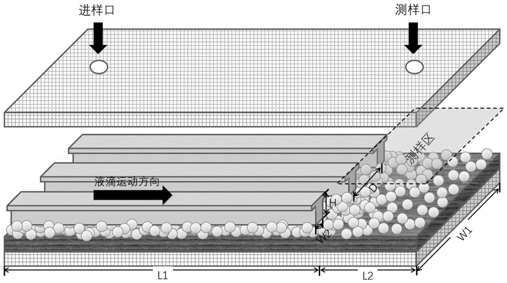
如图1、所示,本实施例提供的一种自驱动的稳定检测的微流控生物芯片,包括:亲水性基底、疏水性微流体通道、封装片、进样口以及测样口。As shown in Figure 1, a self-driven microfluidic biochip for stable detection provided in this embodiment includes: a hydrophilic substrate, a hydrophobic microfluidic channel, a packaging chip, a sample inlet, and a sample port.
所述亲水性基底包括由自下而上依次层叠的基片、亲水储层和纳米级薄疏水盖层,将亲水性基底上表面划分为大小不同的两个区域,并将较小区域作为测样区。本实施例亲水基底为玻璃基片,整体长度为100mm,宽度W1为30mm。其中较大的区域长度L1为75mm,较小的区域长度L2为25mm。The hydrophilic substrate includes a bottom-up layered substrate, a hydrophilic reservoir and a nanoscale thin hydrophobic capping layer, which divides the upper surface of the hydrophilic substrate into two regions of different sizes, and divides the smaller area as the sampling area. In this embodiment, the hydrophilic substrate is a glass substrate, the overall length is 100 mm, and the width W1 is 30 mm. The length L1 of the larger region is 75 mm, and the length L2 of the smaller region is 25 mm.
所述疏水性微流体通道设置在亲水性基底上较大区域上,并与亲水性基底贴合固定,其长度与该区域等长;疏水性微流体通道的截面为“T”型,个数为20~100个,宽度W2为5~50μm,相邻两个结构之间的间距D为20~200μm,高度H为20~30μm。沿液滴输运方向:疏水性微流体通道的宽度和/或相邻两个疏水性微流体通道之间的间距逐渐减小。The hydrophobic microfluidic channel is arranged on a larger area on the hydrophilic substrate, and is attached and fixed to the hydrophilic substrate, and its length is equal to the area; the cross section of the hydrophobic microfluidic channel is "T" shape, The number is 20-100, the width W2 is 5-50 μm, the distance D between two adjacent structures is 20-200 μm, and the height H is 20-30 μm. Along the droplet transport direction: the width of the hydrophobic microfluidic channel and/or the distance between two adjacent hydrophobic microfluidic channels gradually decreases.
所述封装片设于疏水性微流体通道的上方,其底面至疏水性微流体通道顶面的垂直距离为5~11mm。封装片为无色透明材料,其上设有设两个贯穿封装片的通孔,其中一个通孔作为进样口,开设在疏水性微流体通道的上方,另一个通孔作为测样口,开设在测样区域的上方。进样口和测样口均位于封装片宽边中心连线上,且进样口距离封装片远离测样区的一侧宽边10mm,测样口距封装片靠近测样区的一侧宽边为10mm。进样口及测样口可与外界连通。The packaging sheet is arranged above the hydrophobic microfluidic channel, and the vertical distance from its bottom surface to the top surface of the hydrophobic microfluidic channel is 5-11 mm. The encapsulation sheet is a colorless and transparent material, and there are two through holes through the encapsulation sheet, one of which is used as a sample inlet, and is set above the hydrophobic microfluidic channel, and the other through hole is used as a sampling port. Set above the sample area. Both the sampling port and the sampling port are located on the center line of the wide side of the packaging sheet, and the sampling port is 10 mm away from the wide side of the packaging sheet away from the sample area, and the sampling port is 10 mm away from the side of the packaging sheet close to the sample area. The sides are 10mm. The sampling port and the sampling port can be communicated with the outside world.
本实施例所述疏水性微流体通道为一个支撑结构和设于支撑结构顶面的台面组成,且台面的宽度大于支撑结构的宽度,同时,台面被设计为提供液滴悬挂点的内凹结构。所述内凹结构为台面顶部与台面侧壁形成的转角,转角角度为0~180度。The hydrophobic microfluidic channel described in this embodiment is composed of a support structure and a table on the top surface of the support structure, and the width of the table is larger than the width of the support structure. At the same time, the table is designed as a concave structure that provides a suspension point for droplets . The concave structure is a corner formed by the top of the mesa and the side wall of the mesa, and the angle of the corner is 0-180 degrees.
为使分析环境长时间保持干燥,避免污染与残留,增加检测结果的准确性。本实施例亲水性基底由自下而上依次层叠的玻璃基片、亲水储层和纳米级薄疏水盖层构成。所述亲水性基底的基片为玻璃基片,亲水储层为壳聚糖D-葡萄糖胺(CHI)和羧甲基纤维素(CMC)交替的聚合物薄膜;其制备采用静电自组装法,逐层交替沉积CHI和CMC。所述CHI/CMC双分子层数为20~40层,聚合物薄膜厚度为1200~2400nm,其厚度根据CHI/CMC双分子层数进行微调,所述纳米级薄疏水盖层为二氧化硅纳米颗粒,通过分层组装的方式沉积在亲水储层上。In order to keep the analysis environment dry for a long time, avoid pollution and residue, and increase the accuracy of the test results. In this embodiment, the hydrophilic substrate is composed of a glass substrate, a hydrophilic reservoir layer and a nanoscale thin hydrophobic capping layer sequentially stacked from bottom to top. The substrate of the hydrophilic substrate is a glass substrate, and the hydrophilic reservoir layer is an alternating polymer film of chitosan D-glucosamine (CHI) and carboxymethylcellulose (CMC); its preparation adopts electrostatic self-assembly method, alternately depositing CHI and CMC layer by layer. The number of CHI/CMC bimolecular layers is 20-40 layers, and the thickness of the polymer film is 1200-2400nm. The thickness is fine-tuned according to the number of CHI/CMC bimolecular layers. Particles are deposited on a hydrophilic reservoir by layered assembly.
疏水性微流体通道作为本实施例生物芯片的核心部件,其在亲水性基底上的制备过程如图2所示,包括以下步骤:As the core component of the biochip in this embodiment, the hydrophobic microfluidic channel is prepared on a hydrophilic substrate as shown in Figure 2, including the following steps:
a1、采用光刻工艺在光刻胶上制备至少2条疏水性微流体通道模板;a1. Prepare at least 2 hydrophobic microfluidic channel templates on the photoresist by photolithography process;
a2、向疏水性微流体通道模板中注入聚二甲基硅氧烷(PDMS),并依次通过固化、翻转、分离得到反向的疏水性微流体通道PDMS微井;a2. Inject polydimethylsiloxane (PDMS) into the hydrophobic microfluidic channel template, and obtain reversed hydrophobic microfluidic channel PDMS microwells through solidification, flipping, and separation in sequence;
a3、将聚氨酯甲基丙烯酸酯(PFPE)的预聚物填充到PDMS微井中,并将其与注入了硅油的亲水性基底充分接触贴合,去除多余的PFPE,随后经紫外线光固化、分离冲洗、干燥后,成功将疏水性微流体通道转移到亲水性性基底上。a3. Fill the prepolymer of polyurethane methacrylate (PFPE) into the PDMS microwell, and fully contact and bond it with the hydrophilic substrate injected with silicone oil, remove excess PFPE, and then cure and separate by ultraviolet light After rinsing and drying, the hydrophobic microfluidic channels were successfully transferred to the hydrophilic substrate.
本实施例自驱动液滴定向运动是通过浸润性梯度实现的,其浸润性梯度的形成为:沿液滴运动方向,疏水性微流体通道的宽度逐渐变窄。如图3所示,疏水性微流体通道的进样口宽,测样口窄,呈放射状自进样口向测样口收紧,根据工艺难度及运输速度,进样口处结构宽度与测样口处结构宽度比优选为2:1~4:1。In this embodiment, the directional movement of the self-driven droplet is realized through the wettability gradient, and the wettability gradient is formed as follows: along the moving direction of the droplet, the width of the hydrophobic microfluidic channel gradually narrows. As shown in Figure 3, the injection port of the hydrophobic microfluidic channel is wide and the sampling port is narrow, radially tightening from the sampling port to the sampling port. The structure width ratio at the sample port is preferably 2:1-4:1.
利用上述一种自驱动的稳定检测的微流控生物芯片对牛血清白蛋白分子进行快检测,检测方法仍然利用典型的双缩脲法对蛋白质进行定性和定量检测;包括以下步骤:Using the above self-driven stable detection microfluidic biochip to quickly detect bovine serum albumin molecules, the detection method still uses the typical biuret method for qualitative and quantitative detection of proteins; including the following steps:
步骤b1、将0.01g/mL硫酸铜的酒石酸钾钠溶液加入到0.1g/mL氢氧化钠溶液中,摇匀后获得双缩脲试剂;Step b1, adding 0.01g/mL copper sulfate potassium sodium tartrate solution into 0.1g/mL sodium hydroxide solution, shaking well to obtain biuret reagent;
步骤b2、分别取10μL双缩脲试剂和10μL待测蛋白质溶液分别置于进样口及测样口,通过自驱动的方式使双缩脲试剂自发地向待测蛋白质溶液移动并混合;In step b2, take 10 μL of biuret reagent and 10 μL of the protein solution to be tested and place them in the sample inlet and the sample test port respectively, and make the biuret reagent move to the protein solution to be tested spontaneously and mix by self-driving;
步骤b3、通过肉眼观测液滴在分析浓缩前后的变化,或利用紫外-可见分光光度计测量液滴在分析浓缩前后的变化,完成蛋白质的定性及定量/半定量分析。In step b3, the qualitative and quantitative/semi-quantitative analysis of the protein is completed by visually observing the changes of the droplets before and after analysis and concentration, or by using a UV-visible spectrophotometer to measure the changes of the droplets before and after analysis and concentration.
实施例2Example 2
本实施例提供的一种自驱动的稳定检测的微流控生物芯片,结构与实施例1基本相同,其与实施例1的区别在于:The self-driven stable detection microfluidic biochip provided in this embodiment has basically the same structure as that of Embodiment 1, and its difference from Embodiment 1 lies in:
疏水性微流体通道宽度及相邻两个疏水性微流体通道之间的间距均相等,且需先采用液滴多次撞击纳米级薄疏水盖层表面,以使其形成电荷梯度,控制滴液产生方向性运动。电荷梯度的实现方式为:The width of the hydrophobic microfluidic channel and the distance between two adjacent hydrophobic microfluidic channels are equal, and it is necessary to use the droplet to hit the surface of the nanoscale thin hydrophobic cover layer many times to form a charge gradient and control the droplet flow. Produce directional movement. The charge gradient is realized by:
如图4所示,当液滴以较低速度撞击二氧化硅纳米颗粒表面时,会发生相对较弱的电荷分离,但若多次在相同位置撞击,表面电荷的强度则会逐渐累积增强,通过法拉第杯控制撞击位置和次数,可以产生带有电荷梯度的亲水储层表面;其中液滴撞击表面的高度为10mm,液滴大小为10μL,撞击次数为1~20次。As shown in Figure 4, when a droplet hits the surface of a silica nanoparticle at a low velocity, relatively weak charge separation occurs, but if it hits the same location multiple times, the strength of the surface charge gradually increases, Controlling the position and number of impacts through the Faraday cup can produce a hydrophilic reservoir surface with a charge gradient; the height of the droplet impacting the surface is 10 mm, the droplet size is 10 μL, and the number of impacts is 1 to 20 times.
本实施例用于撞击表面产生电荷梯度的液滴为水或氯化钠溶液。In this embodiment, the droplets used to strike the surface to generate the charge gradient are water or sodium chloride solution.
利用本实施例的一种自驱动的稳定检测的微流控生物芯片对牛血清白蛋白分子进行快检测,检测方法仍然利用典型的双缩脲法对蛋白质进行定性和定量检测;包括以下步骤:Utilize a self-driven stable detection microfluidic biochip of this embodiment to quickly detect bovine serum albumin molecules, and the detection method still uses the typical biuret method to perform qualitative and quantitative detection of proteins; including the following steps:
步骤b1、将0.01g/mL硫酸铜的酒石酸钾钠溶液加入到0.1g/mL氢氧化钠溶液中,摇匀后获得双缩脲试剂;Step b1, adding 0.01g/mL copper sulfate potassium sodium tartrate solution into 0.1g/mL sodium hydroxide solution, shaking well to obtain biuret reagent;
步骤b2、分别取10μL双缩脲试剂和10μL待测蛋白质溶液分别置于进样口及测样口,通过自驱动的方式使双缩脲试剂自发地向待测蛋白质溶液移动并混合;In step b2, take 10 μL of biuret reagent and 10 μL of the protein solution to be tested and place them in the sample inlet and the sample test port respectively, and make the biuret reagent move to the protein solution to be tested spontaneously and mix by self-driving;
步骤b3、通过肉眼观测液滴在分析浓缩前后的变化,或利用紫外-可见分光光度计测量液滴在分析浓缩前后的变化,完成蛋白质的定性及定量/半定量分析。In step b3, the qualitative and quantitative/semi-quantitative analysis of the protein is completed by visually observing the changes of the droplets before and after analysis and concentration, or by using a UV-visible spectrophotometer to measure the changes of the droplets before and after analysis and concentration.
综上可知,本发明提出了一种自驱动的稳定检测的微流控生物芯片及其制备方式,微液滴的自输运可以依靠材料表面能量梯度的引入来实现,若将能量梯度引入微液滴的操控表面,本发明中梯度表面的构筑主要是通过电荷梯度表面和浸润性梯度表面;通过单凹结构的引入来提高液滴自运输时的稳定性,同时将基底设计为亲水基底,能使分析环境长时间保持干燥,避免污染与残留,增加检测结果的准确性。In summary, the present invention proposes a self-driven stable detection microfluidic biochip and its preparation method. The self-transport of microdroplets can be achieved by introducing the energy gradient on the surface of the material. If the energy gradient is introduced into the microfluidic biochip The control surface of the droplet, the construction of the gradient surface in the present invention is mainly through the charge gradient surface and the wettability gradient surface; the stability of the droplet self-transport is improved through the introduction of a single concave structure, and the substrate is designed as a hydrophilic substrate , can keep the analysis environment dry for a long time, avoid pollution and residue, and increase the accuracy of test results.
前述对本发明的具体示例性实施方案的描述是为了说明和例证的目的。这些描述并非想将本发明限定为所公开的精确形式,并且很显然,根据上述教导,可以进行很多改变和变化。对示例性实施例进行选择和描述的目的在于解释本发明的特定原理及其实际应用,从而使得本领域的技术人员能够实现并利用本发明的各种不同的示例性实施方案以及各种不同的选择和改变。本发明的范围意在由权利要求书及其等同形式所限定。The foregoing descriptions of specific exemplary embodiments of the present invention have been presented for purposes of illustration and description. These descriptions are not intended to limit the invention to the precise form disclosed, and obviously many modifications and variations are possible in light of the above teaching. The exemplary embodiments were chosen and described in order to explain the specific principles of the invention and its practical application, thereby enabling others skilled in the art to make and use various exemplary embodiments of the invention, as well as various Choose and change. It is intended that the scope of the invention be defined by the claims and their equivalents.
Claims (9)
Priority Applications (1)
| Application Number | Priority Date | Filing Date | Title |
|---|---|---|---|
| CN202310374318.5A CN116139957A (en) | 2023-04-10 | 2023-04-10 | A self-driven microfluidic biochip with stable detection and its application |
Applications Claiming Priority (1)
| Application Number | Priority Date | Filing Date | Title |
|---|---|---|---|
| CN202310374318.5A CN116139957A (en) | 2023-04-10 | 2023-04-10 | A self-driven microfluidic biochip with stable detection and its application |
Publications (1)
| Publication Number | Publication Date |
|---|---|
| CN116139957A true CN116139957A (en) | 2023-05-23 |
Family
ID=86358437
Family Applications (1)
| Application Number | Title | Priority Date | Filing Date |
|---|---|---|---|
| CN202310374318.5A Pending CN116139957A (en) | 2023-04-10 | 2023-04-10 | A self-driven microfluidic biochip with stable detection and its application |
Country Status (1)
| Country | Link |
|---|---|
| CN (1) | CN116139957A (en) |
Cited By (1)
| Publication number | Priority date | Publication date | Assignee | Title |
|---|---|---|---|---|
| CN118904408A (en) * | 2023-06-20 | 2024-11-08 | 西湖大学 | Dynamically reconfigurable, programmable microfluidic system and applications thereof |
Citations (7)
| Publication number | Priority date | Publication date | Assignee | Title |
|---|---|---|---|---|
| US20070034270A1 (en) * | 2005-08-09 | 2007-02-15 | Jing-Tang Yang | Microfluidic separating and transporting device |
| JP2007196090A (en) * | 2006-01-24 | 2007-08-09 | Seiko Instruments Inc | Micro channel device and sending process of liquid |
| KR100758274B1 (en) * | 2006-09-27 | 2007-09-12 | 한국전자통신연구원 | A microfluidic device for equalizing the flow of multiple microfluids in the chamber, and a microfluidic network using the same |
| WO2009121037A2 (en) * | 2008-03-27 | 2009-10-01 | President And Fellows Of Harvard College | Three-dimensional microfluidic devices |
| WO2013044222A2 (en) * | 2011-09-23 | 2013-03-28 | Board Of Governors For Higher Education, State Of Rhode Island And Providence Plantations | Systems and methods for providing microfluidic devices |
| CN108472647A (en) * | 2015-10-16 | 2018-08-31 | 牛津大学科技创新有限公司 | Microfluid is arranged |
| CN111359683A (en) * | 2019-12-03 | 2020-07-03 | 北京信息科技大学 | Gradient microfluidic channel for unpowered droplet transport and preparation method thereof |
-
2023
- 2023-04-10 CN CN202310374318.5A patent/CN116139957A/en active Pending
Patent Citations (7)
| Publication number | Priority date | Publication date | Assignee | Title |
|---|---|---|---|---|
| US20070034270A1 (en) * | 2005-08-09 | 2007-02-15 | Jing-Tang Yang | Microfluidic separating and transporting device |
| JP2007196090A (en) * | 2006-01-24 | 2007-08-09 | Seiko Instruments Inc | Micro channel device and sending process of liquid |
| KR100758274B1 (en) * | 2006-09-27 | 2007-09-12 | 한국전자통신연구원 | A microfluidic device for equalizing the flow of multiple microfluids in the chamber, and a microfluidic network using the same |
| WO2009121037A2 (en) * | 2008-03-27 | 2009-10-01 | President And Fellows Of Harvard College | Three-dimensional microfluidic devices |
| WO2013044222A2 (en) * | 2011-09-23 | 2013-03-28 | Board Of Governors For Higher Education, State Of Rhode Island And Providence Plantations | Systems and methods for providing microfluidic devices |
| CN108472647A (en) * | 2015-10-16 | 2018-08-31 | 牛津大学科技创新有限公司 | Microfluid is arranged |
| CN111359683A (en) * | 2019-12-03 | 2020-07-03 | 北京信息科技大学 | Gradient microfluidic channel for unpowered droplet transport and preparation method thereof |
Non-Patent Citations (1)
| Title |
|---|
| 邓永波;张平;杜新;吴一辉;刘震宇;刘永顺;: "亲/疏水性不同壁面组成微通道的深宽比与通道内液体的自发毛细流动", 光学精密工程, no. 07, 15 July 2010 (2010-07-15), pages 1562 - 1565 * |
Cited By (1)
| Publication number | Priority date | Publication date | Assignee | Title |
|---|---|---|---|---|
| CN118904408A (en) * | 2023-06-20 | 2024-11-08 | 西湖大学 | Dynamically reconfigurable, programmable microfluidic system and applications thereof |
Similar Documents
| Publication | Publication Date | Title |
|---|---|---|
| Song et al. | Microfluidics: fundamentals, devices, and applications | |
| Wilding et al. | Manipulation and flow of biological fluids in straight channels micromachined in silicon | |
| Sin et al. | System integration-A major step toward lab on a chip | |
| US6919058B2 (en) | Retaining microfluidic microcavity and other microfluidic structures | |
| US20040009614A1 (en) | Magnetic bead-based arrays | |
| Shikida et al. | Development of an enzymatic reaction device using magnetic bead-cluster handling | |
| CN101587123A (en) | Special micro-fluidic chip for cholera diagnosis with one-dimensional self-assembly magnetic bead chain electrodes | |
| US20080213853A1 (en) | Magnetofluidics | |
| WO2007101174A2 (en) | Digital magnetofluidic devices and methods | |
| EP1483052B1 (en) | Retaining microfluidic microcavity and other microfluidic structures | |
| JP2018538124A (en) | Microfluidic device | |
| CN103934049B (en) | A kind of quantitative care diagnostic micro-fluidic chip of scale-type and preparation method thereof | |
| Hu et al. | Versatile microfluidic droplets array for bioanalysis | |
| CN112041072B (en) | Magnetic digital microfluidic device and magnetic digital microfluidic manipulation method | |
| WO2009086624A1 (en) | Microfluidic microarray system and method for the multiplexed analysis of biomolecules | |
| CN105015200A (en) | Optical microfluidics chip for fixing monoclonal antibody modified layer based on nanometer seal | |
| CN107737615A (en) | A microfluidic device for biochemical detection | |
| Phurimsak et al. | Phaseguide assisted liquid lamination for magnetic particle-based assays | |
| CN106179545B (en) | Microfluidic chip device for biological analysis and preparation method thereof | |
| CN116139957A (en) | A self-driven microfluidic biochip with stable detection and its application | |
| Sista | Development of a digital microfluidic lab-on-a-chip for automated immunoassay with magnetically responsive beads | |
| Chartier et al. | Fabrication of hybrid plastic-silicon microfluidic devices for individual cell manipulation by dielectrophoresis | |
| CN107661784A (en) | After a kind of quantitative shunting be pre-stored in liquid hybrid detection micro-fluidic chip | |
| Paul et al. | A “dry and wet hybrid” lithography technique for multilevel replication templates: Applications to microfluidic neuron culture and two-phase global mixing | |
| Jin et al. | Nanoliter-scale liquid metering and droplet generation based on a capillary array for high throughput screening |
Legal Events
| Date | Code | Title | Description |
|---|---|---|---|
| PB01 | Publication | ||
| PB01 | Publication | ||
| SE01 | Entry into force of request for substantive examination | ||
| SE01 | Entry into force of request for substantive examination |