[go: up one dir, main page]

CN116116597A - Mixing chamber for a multipart applicator - Google Patents

Mixing chamber for a multipart applicator Download PDF

Info

Publication number
CN116116597A
CN116116597A CN202310286750.9A CN202310286750A CN116116597A CN 116116597 A CN116116597 A CN 116116597A CN 202310286750 A CN202310286750 A CN 202310286750A CN 116116597 A CN116116597 A CN 116116597A
Authority
CN
China
Prior art keywords
mixing chamber
mixing
chamber
extending
planar
Prior art date
Legal status (The legal status is an assumption and is not a legal conclusion. Google has not performed a legal analysis and makes no representation as to the accuracy of the status listed.)
Pending
Application number
CN202310286750.9A
Other languages
Chinese (zh)
Inventor
丹尼尔·P·罗斯
约瑟夫·E·提克斯
塞缪尔·R·斯图尔特
马克·T·温伯格
克里斯多夫·J·佩林
杰弗里·N·韦尔戈斯迪克
杰克·A·博萨克
雅各布·R·怀特奥亚克
Current Assignee (The listed assignees may be inaccurate. Google has not performed a legal analysis and makes no representation or warranty as to the accuracy of the list.)
Graco Minnesota Inc
Original Assignee
Graco Minnesota Inc
Priority date (The priority date is an assumption and is not a legal conclusion. Google has not performed a legal analysis and makes no representation as to the accuracy of the date listed.)
Filing date
Publication date
Application filed by Graco Minnesota Inc filed Critical Graco Minnesota Inc
Publication of CN116116597A publication Critical patent/CN116116597A/en
Pending legal-status Critical Current

Links

Images

Classifications

    • BPERFORMING OPERATIONS; TRANSPORTING
    • B05SPRAYING OR ATOMISING IN GENERAL; APPLYING FLUENT MATERIALS TO SURFACES, IN GENERAL
    • B05BSPRAYING APPARATUS; ATOMISING APPARATUS; NOZZLES
    • B05B7/00Spraying apparatus for discharge of liquids or other fluent materials from two or more sources, e.g. of liquid and air, of powder and gas
    • B05B7/02Spray pistols; Apparatus for discharge
    • B05B7/04Spray pistols; Apparatus for discharge with arrangements for mixing liquids or other fluent materials before discharge
    • B05B7/0408Spray pistols; Apparatus for discharge with arrangements for mixing liquids or other fluent materials before discharge with arrangements for mixing two or more liquids
    • BPERFORMING OPERATIONS; TRANSPORTING
    • B05SPRAYING OR ATOMISING IN GENERAL; APPLYING FLUENT MATERIALS TO SURFACES, IN GENERAL
    • B05BSPRAYING APPARATUS; ATOMISING APPARATUS; NOZZLES
    • B05B7/00Spraying apparatus for discharge of liquids or other fluent materials from two or more sources, e.g. of liquid and air, of powder and gas
    • B05B7/24Spraying apparatus for discharge of liquids or other fluent materials from two or more sources, e.g. of liquid and air, of powder and gas with means, e.g. a container, for supplying liquid or other fluent material to a discharge device
    • B05B7/2489Spraying apparatus for discharge of liquids or other fluent materials from two or more sources, e.g. of liquid and air, of powder and gas with means, e.g. a container, for supplying liquid or other fluent material to a discharge device an atomising fluid, e.g. a gas, being supplied to the discharge device
    • B05B7/2497Spraying apparatus for discharge of liquids or other fluent materials from two or more sources, e.g. of liquid and air, of powder and gas with means, e.g. a container, for supplying liquid or other fluent material to a discharge device an atomising fluid, e.g. a gas, being supplied to the discharge device several liquids from different sources being supplied to the discharge device
    • BPERFORMING OPERATIONS; TRANSPORTING
    • B01PHYSICAL OR CHEMICAL PROCESSES OR APPARATUS IN GENERAL
    • B01FMIXING, e.g. DISSOLVING, EMULSIFYING OR DISPERSING
    • B01F35/00Accessories for mixers; Auxiliary operations or auxiliary devices; Parts or details of general application
    • B01F35/50Mixing receptacles
    • B01F35/52Receptacles with two or more compartments
    • B01F35/522Receptacles with two or more compartments comprising compartments keeping the materials to be mixed separated until the mixing is initiated
    • BPERFORMING OPERATIONS; TRANSPORTING
    • B05SPRAYING OR ATOMISING IN GENERAL; APPLYING FLUENT MATERIALS TO SURFACES, IN GENERAL
    • B05BSPRAYING APPARATUS; ATOMISING APPARATUS; NOZZLES
    • B05B15/00Details of spraying plant or spraying apparatus not otherwise provided for; Accessories
    • B05B15/50Arrangements for cleaning; Arrangements for preventing deposits, drying-out or blockage; Arrangements for detecting improper discharge caused by the presence of foreign matter
    • B05B15/55Arrangements for cleaning; Arrangements for preventing deposits, drying-out or blockage; Arrangements for detecting improper discharge caused by the presence of foreign matter using cleaning fluids
    • BPERFORMING OPERATIONS; TRANSPORTING
    • B05SPRAYING OR ATOMISING IN GENERAL; APPLYING FLUENT MATERIALS TO SURFACES, IN GENERAL
    • B05BSPRAYING APPARATUS; ATOMISING APPARATUS; NOZZLES
    • B05B7/00Spraying apparatus for discharge of liquids or other fluent materials from two or more sources, e.g. of liquid and air, of powder and gas
    • B05B7/02Spray pistols; Apparatus for discharge
    • B05B7/04Spray pistols; Apparatus for discharge with arrangements for mixing liquids or other fluent materials before discharge
    • BPERFORMING OPERATIONS; TRANSPORTING
    • B05SPRAYING OR ATOMISING IN GENERAL; APPLYING FLUENT MATERIALS TO SURFACES, IN GENERAL
    • B05BSPRAYING APPARATUS; ATOMISING APPARATUS; NOZZLES
    • B05B7/00Spraying apparatus for discharge of liquids or other fluent materials from two or more sources, e.g. of liquid and air, of powder and gas
    • B05B7/02Spray pistols; Apparatus for discharge
    • B05B7/08Spray pistols; Apparatus for discharge with separate outlet orifices, e.g. to form parallel jets, i.e. the axis of the jets being parallel, to form intersecting jets, i.e. the axis of the jets converging but not necessarily intersecting at a point
    • BPERFORMING OPERATIONS; TRANSPORTING
    • B05SPRAYING OR ATOMISING IN GENERAL; APPLYING FLUENT MATERIALS TO SURFACES, IN GENERAL
    • B05BSPRAYING APPARATUS; ATOMISING APPARATUS; NOZZLES
    • B05B7/00Spraying apparatus for discharge of liquids or other fluent materials from two or more sources, e.g. of liquid and air, of powder and gas
    • B05B7/02Spray pistols; Apparatus for discharge
    • B05B7/12Spray pistols; Apparatus for discharge designed to control volume of flow, e.g. with adjustable passages
    • B05B7/1254Spray pistols; Apparatus for discharge designed to control volume of flow, e.g. with adjustable passages the controlling means being fluid actuated
    • B05B7/1263Spray pistols; Apparatus for discharge designed to control volume of flow, e.g. with adjustable passages the controlling means being fluid actuated pneumatically actuated
    • B05B7/1272Spray pistols; Apparatus for discharge designed to control volume of flow, e.g. with adjustable passages the controlling means being fluid actuated pneumatically actuated actuated by gas involved in spraying, i.e. exiting the nozzle, e.g. as a spraying or jet shaping gas
    • BPERFORMING OPERATIONS; TRANSPORTING
    • B05SPRAYING OR ATOMISING IN GENERAL; APPLYING FLUENT MATERIALS TO SURFACES, IN GENERAL
    • B05BSPRAYING APPARATUS; ATOMISING APPARATUS; NOZZLES
    • B05B1/00Nozzles, spray heads or other outlets, with or without auxiliary devices such as valves, heating means
    • B05B1/30Nozzles, spray heads or other outlets, with or without auxiliary devices such as valves, heating means designed to control volume of flow, e.g. with adjustable passages
    • B05B1/3026Gate valves; Sliding valves; Cocks

Landscapes

  • Chemical & Material Sciences (AREA)
  • Chemical Kinetics & Catalysis (AREA)
  • Nozzles (AREA)

Abstract

用于多部件式喷涂器的混合腔被配置成接收第一成分物料和第二成分物料并发射产生的多成分物料的喷剂。所述混合腔包括在第一端与第二端之间延伸并且包括平坦的横向侧面的腔主体。斜面特征部被配置在所述第一端附近并且被配置成当所述混合腔沿第一方向移动通过盒孔时分别接触第一侧部密封件和第二侧部密封件并推动所述第一侧部密封件和第二侧部密封件远离主体轴线,以增大所述第一侧部密封件与所述第二侧部密封件之间的间隙,使得所述第一侧部密封件接合平坦的第一横向侧面并且所述第二侧部密封件接合平坦的第二横向侧面。

Figure 202310286750

A mixing chamber for a multi-component sprayer is configured to receive a first component material and a second component material and emit a resulting spray of the multi-component material. The mixing chamber includes a chamber body extending between a first end and a second end and including planar lateral sides. A ramp feature is disposed adjacent the first end and is configured to contact the first side seal and the second side seal, respectively, and push the first side seal when the mixing chamber moves through the cartridge bore in a first direction. One side seal and the second side seal are moved away from the body axis to increase the gap between the first side seal and the second side seal such that the first side seal The second side seal engages the flat first lateral side and the second side seal engages the flat second lateral side.

Figure 202310286750

Description

用于多部件式喷涂器的混合腔Mixing chambers for multi-component applicators

本申请是申请人为“固瑞克明尼苏达有限公司”的进入中国国家阶段日期为2021年04月23日的申请号为201980070293.1的发明名称为“用于多部件式喷涂器的混合腔”的专利申请(国际申请日为2019年10月25日,国际申请号为PCT/US2019/058101)的分案申请。This application is a patent application of the applicant "Graco Minnesota Co., Ltd." with the date of entry into the Chinese national phase on April 23, 2021, the application number is 201980070293.1, and the invention name is "Mixing chamber for multi-component sprayer" (The international filing date is October 25, 2019, and the international application number is PCT/US2019/058101).

相关申请的交叉引用Cross References to Related Applications

本申请要求2018年10月26日递交的标题为“REPLACEABLE HEAD FOR PLURALCOMPONENT SPRAYER(GUN)(用于多部件式喷涂器(枪)的可更换头部)”的美国临时申请号62/751,148的权益和2019年2月4日递交的标题为“MIXING CARTRIDGE AND MIXINGCARTRIDGE ASSEMBLY FOR PLURAL COMPONENT SPRAYER(用于多部件式喷涂器的混合盒和混合盒组件)”的美国临时申请号62/800,659的权益,这些美国临时申请的公开内容由此通过引用其全部内容而被并入本文中。This application claims U.S. Provisional Application No. 62/751,148, filed October 26, 2018, entitled "REPLACEABLE HEAD FOR PLURALCOMPONENT SPRAYER (GUN)" and U.S. Provisional Application No. 62/800,659, entitled "MIXING CARTRIDGE AND MIXING CARTRIDGE ASSEMBLY FOR PLURAL COMPONENT SPRAYER," filed February 4, 2019 , the disclosures of these U.S. provisional applications are hereby incorporated by reference in their entirety.

技术领域technical field

本公开涉及喷涂器。更特别地,本公开涉及多部件式喷涂枪。This disclosure relates to sprayers. More particularly, the present disclosure relates to multi-component spray guns.

背景技术Background technique

多部件式喷涂器接收多种成分物料并将所述多种成分物料结合以形成多成分物料。例如,一些多部件式喷涂器接收催化剂(诸如异氰酸盐)和树脂,所述催化剂和树脂结合以形成喷涂泡沫。喷涂泡沫隔热物可以被施加至基材以提供隔热。所述喷涂枪被触发以打开从所述枪出去的通路并喷射所述多成分物料。所述成分物料可能窜流(cross-over)到其它成分物料的通路中,这可能导致所述枪内的固化。多部件式喷涂器的修理要求折卸整个流体头部以供维护、维修,并要求解决可能引发喷涂故障的任何问题。A multi-component sprayer receives multiple component materials and combines the multiple component materials to form a multicomponent material. For example, some multi-component sprayers receive a catalyst, such as isocyanate, and a resin that combine to form a spray foam. Spray foam insulation can be applied to substrates to provide insulation. The spray gun is triggered to open a passage out of the gun and spray the multi-component material. The constituent materials may cross-over into the pathways of other constituent materials, which may lead to solidification within the gun. Repair of multi-component applicators requires disassembly of the entire fluid head for maintenance, repair, and resolution of any problems that may cause spraying failures.

发明内容Contents of the invention

根据本公开的一个方面,混合腔被配置成设置在喷涂枪中的盒孔中,以从所述喷涂枪中的第一流体通道接收第一成分流体并从所述喷涂枪中的第二流体通道接收第二成分流体,第一侧部密封件被设置在所述第一流体通道中以密封所述混合腔,并且第二侧部密封件被设置在所述第二流体通道中以密封所述混合腔。所述混合腔包括在第一端与第二端之间延伸且沿主体轴线伸长的腔主体,所述腔主体包括平坦的第一横向侧面和平坦的第二横向侧面。所述混合腔还包括:延伸到所述平坦的第一横向侧面中且延伸至混合孔的第一入口孔,所述混合孔延伸至喷涂孔口,所述第一入口孔被配置成从所述第一流体通道接收所述第一成分流体;延伸到所述平坦的第二横向侧面中且延伸至所述混合孔的第二入口孔,所述第二入口孔被配置成从所述第二流体通道接收所述第二成分流体;以及设置在所述第一端附近的斜面特征部。所述斜面特征部被配置成当所述混合腔沿第一方向移动通过所述盒孔时分别接触所述第一侧部密封件和第二侧部密封件并推动所述第一侧部密封件和第二侧部密封件远离所述主体轴线,以增大所述第一侧部密封件与所述第二侧部密封件之间的间隙,使得所述第一侧部密封件接合所述第一横向侧面并且所述第二侧部密封件接合所述第二横向侧面。According to one aspect of the present disclosure, the mixing chamber is configured to be disposed in a cartridge bore in a spray gun to receive a first component fluid from a first fluid passage in the spray gun and a second fluid from the spray gun. A channel receives a second component fluid, a first side seal is disposed in the first fluid channel to seal the mixing chamber, and a second side seal is disposed in the second fluid channel to seal the mixing chamber. the mixing chamber. The mixing chamber includes a chamber body extending between a first end and a second end and elongated along a body axis, the chamber body including a first planar lateral side and a second planar lateral side. The mixing chamber further includes a first inlet hole extending into the planar first lateral side and to a mixing hole extending to a spraying orifice, the first inlet hole being configured to pass from the the first fluid passage receives the first component fluid; a second inlet hole extending into the flat second lateral side and to the mixing hole, the second inlet hole configured to flow from the first A second fluid channel receives the second component fluid; and a ramp feature disposed near the first end. The ramp feature is configured to contact the first side seal and the second side seal respectively and push the first side seal when the mixing chamber is moved in a first direction through the cartridge aperture. and the second side seal away from the body axis to increase the gap between the first side seal and the second side seal such that the first side seal engages the The first lateral side and the second side seal engages the second lateral side.

根据本公开的另一方面,在多部件式喷涂枪中进行组装的方法包括:将混合腔附接至所述多部件式喷涂枪的致动器;使流体盒在所述混合腔上沿第一方向行进,使得所述混合腔通过所述流体盒进入盒孔的后部开口中;将设置在所述流体盒中的第一密封构件和第二密封构件与所述混合腔的斜面特征部接合,所述斜面特征部是所述混合腔的用于接触所述第一密封构件和第二密封构件的第一部分,其中所述第一密封构件和第二密封构件被预加载,使得弹簧力将所述第一密封构件和第二密封构件至少部分地偏压到所述盒孔中;通过所述斜面特征部来推动所述第一密封构件和第二密封构件远离腔轴线,以加宽所述第一密封构件和第二密封构件之间的间隙;以及使所述第一密封构件从所述斜面特征部行进到所述混合腔的平坦的第一横向侧面上,并且使所述第二密封构件行进到所述混合腔的平坦的第二横向侧面上。According to another aspect of the present disclosure, a method of assembling in a multi-part spray gun includes: attaching a mixing chamber to an actuator of the multi-part spray gun; travel in one direction so that the mixing chamber passes through the fluid box into the rear opening of the box bore; align a first sealing member and a second sealing member disposed in the fluid box with the ramp feature of the mixing chamber engagement, the ramp feature is the first portion of the mixing chamber for contacting the first and second sealing members, wherein the first and second sealing members are preloaded such that the spring force biasing the first and second sealing members at least partially into the cartridge bore; urging the first and second sealing members away from the cavity axis by the ramp feature to widen a gap between the first sealing member and a second sealing member; and causing the first sealing member to travel from the ramp feature onto the flat first lateral side of the mixing chamber and causing the second Two sealing members run onto the flat second lateral side of the mixing chamber.

根据本公开的又一方面,用于多部件式喷涂器的流体盒包括:盒主体,所述盒主体具有第一端和第二端;盒孔,所述盒孔在所述第一端与所述第二端之间轴向地延伸穿过所述主体;从所述第二端延伸至所述盒孔的第一物料流路和从所述第二端延伸至所述盒孔的第二物料流路;在所述第一物料路径中设置在所述第一物料路径的第一入口附近的第一流体止回件和在所述第二物料路径中设置在所述第二物料路径的第二入口附近的第二流体止回件,所述第一流体止回件和第二流体止回件被设置成防止物料通过所述第一入口和第二入口的回流;在所述盒孔附近设置在所述第一物料路径中的第一侧部密封件,所述第一侧部密封件包括第一密封构件和第一侧部弹簧,所述第一侧部弹簧将所述第一密封构件至少部分地偏压到所述盒孔中,使得所述第一侧部密封件被预加载;以及在所述盒孔附近设置在所述第二物料路径中的第二侧部密封件,所述第二侧部密封件包括第二密封构件和第二侧部弹簧,所述第二侧部弹簧将所述第二密封构件至少部分地偏压到所述盒孔中,使得所述第二侧部密封件被预加载。According to yet another aspect of the present disclosure, a fluid cartridge for a multi-part applicator includes a cartridge body having a first end and a second end, and a cartridge aperture between the first end and the second end. The second ends extend axially through the main body; the first material flow path extending from the second end to the box hole and the first material flow path extending from the second end to the box hole Two material flow paths; a first fluid check member disposed in the first material path near the first inlet of the first material path and a fluid check member disposed in the second material path in the second material path a second fluid check near the second inlet of the box, the first fluid check and the second fluid check being arranged to prevent backflow of material through the first inlet and the second inlet; a first side seal disposed in the first material path near the hole, the first side seal comprising a first sealing member and a first side spring, the first side spring connecting the first a sealing member at least partially biased into the cassette bore such that the first side seal is preloaded; and a second side seal disposed in the second material path adjacent the cassette bore part, the second side seal includes a second seal member and a second side spring, the second side spring biases the second seal member at least partially into the cartridge bore such that the The second side seal is preloaded.

根据本公开的又一方面,用于在所述多部件式喷涂器中使用的流体盒被配置成从所述多部件式喷涂器接收第一成分物料和第二成分物料、并从所述多部件式喷涂器接收吹扫空气。所述流体盒包括:限定盒孔的盒主体;安装至所述盒主体的第一密封壳体,所述第一密封壳体包括第一柱,所述第一柱从所述第一密封壳体向后延伸且被配置成被接收在第一物料端口中,以从所述第一物料端口接收所述第一成分物料;安装至所述盒主体的第二密封壳体,所述第二密封壳体包括第二柱,所述第二柱从所述第二密封壳体向后延伸且被配置成被接收在第二物料端口中,以从所述第二物料端口接收所述第二成分物料;第三柱,所述第三柱从所述盒主体向后延伸且配置成被接收在吹扫端口中,以从所述吹扫端口接收吹扫空气;设置在第一物料路径中的第一流体止回件,所述第一物料路径从所述第一柱穿过所述第一密封壳体延伸到所述盒孔;设置在第二物料路径中的第二流体止回件,所述第二物料路径从所述第二柱穿过所述第二密封壳体延伸到所述盒孔;设置在吹扫路径中的第三流体止回件,所述吹扫路径从从第三柱穿过所述盒主体延伸到所述盒孔中的吹扫腔;在所述盒孔附近设置在所述第一物料路径中的第一侧部密封件,所述第一侧部密封件包括第一密封构件和第一侧部弹簧,所述第一侧部弹簧将所述第一密封构件至少部分地偏压到所述盒孔中,使得所述第一侧部密封件被预加载;以及在所述盒孔附近设置在所述第二物料路径中的第二侧部密封件,所述第二侧部密封件包括第二密封构件和第二侧部弹簧,所述第二侧部弹簧将所述第二密封构件至少部分地偏压到所述盒孔中,使得所述第二侧部密封件被预加载。According to yet another aspect of the present disclosure, a fluid cartridge for use in the multi-component sprayer is configured to receive a first component material and a second component material from the multi-component sprayer, and to receive a second component material from the multi-component sprayer. Component applicators receive purge air. The fluid cartridge includes: a cartridge body defining a cartridge aperture; a first seal housing mounted to the cartridge body, the first seal housing including a first post extending from the first seal housing body extending rearwardly and configured to be received in a first material port to receive the first component material from the first material port; a second seal housing mounted to the cartridge body, the second The seal housing includes a second post extending rearwardly from the second seal housing and configured to be received in the second material port to receive the second material port from the second material port. component material; a third post extending rearwardly from the cartridge body and configured to be received in a purge port to receive purge air therefrom; disposed in the first material path a first fluid check member, the first material path extending from the first column through the first seal housing to the cartridge bore; a second fluid check member disposed in the second material path , the second material path extends from the second column through the second sealed housing to the box hole; a third fluid check member is provided in the purge path from the A third post extends through the box body to a purge chamber in the box hole; a first side seal disposed in the first material path adjacent the box hole, the first side The seal includes a first seal member and a first side spring that biases the first seal member at least partially into the cartridge bore such that the first side seal is preload; and a second side seal disposed in the second material path adjacent to the box aperture, the second side seal comprising a second seal member and a second side spring, the first Two side springs bias the second seal member at least partially into the cartridge bore such that the second side seal is preloaded.

附图说明Description of drawings

图1A是多部件式喷涂器的等轴侧视图。Figure 1A is an isometric view of a multi-component sprayer.

图1B是多部件式喷涂器的爆炸图。Figure 1B is an exploded view of a multi-component sprayer.

图2A是沿图1A中的线2-2截取的截面图。FIG. 2A is a cross-sectional view taken along line 2-2 in FIG. 1A.

图2B是图2A中的细节Z的放大图。Figure 2B is an enlarged view of detail Z in Figure 2A.

图3A是沿图1A中的线3-3截取的截面图。3A is a cross-sectional view taken along line 3-3 in FIG. 1A.

图3B是图3A中的细节Y的放大图。Figure 3B is an enlarged view of detail Y in Figure 3A.

图4A是安装头部的主视等轴侧视图。Figure 4A is a front isometric view of a mounting head.

图4B是图4A中示出的所述安装头部的主视立视图。Figure 4B is a front elevational view of the mounting head shown in Figure 4A.

图4C是图4A中示出的所述安装头部的仰视平面图。Figure 4C is a bottom plan view of the mounting head shown in Figure 4A.

图5A是流体盒的第一等轴侧视图。Figure 5A is a first isometric view of a fluid cartridge.

图5B是图5A中示出的所述流体盒的第二等轴侧视图。Figure 5B is a second isometric view of the fluid cartridge shown in Figure 5A.

图6A是混合腔的等轴侧视图。Figure 6A is an isometric view of a mixing chamber.

图6B是图6A中示出的所述混合腔的第一平面图。Figure 6B is a first plan view of the mixing chamber shown in Figure 6A.

图6C是图6A中示出的所述混合腔的第一侧视立视图。Figure 6C is a first side elevational view of the mixing chamber shown in Figure 6A.

图6D是图6A中示出的所述混合腔的第二侧视立视图。Figure 6D is a second side elevational view of the mixing chamber shown in Figure 6A.

图6E是图6A中示出的所述混合腔的第二平面图。Figure 6E is a second plan view of the mixing chamber shown in Figure 6A.

图7A是混合腔的等轴侧视图。Figure 7A is an isometric view of a mixing chamber.

图7B是图7A中示出的所述混合腔的平面图。Figure 7B is a plan view of the mixing chamber shown in Figure 7A.

图8A是混合腔的等轴侧视图。Figure 8A is an isometric view of a mixing chamber.

图8B是图8A中示出的所述混合腔的主视立视图。Figure 8B is a front elevational view of the mixing chamber shown in Figure 8A.

图9A是混合腔的第一等轴侧视图。Figure 9A is a first isometric view of a mixing chamber.

图9B是图9A中示出的所述混合腔的第二等轴侧视图。Figure 9B is a second isometric view of the mixing chamber shown in Figure 9A.

图10A是混合腔组件的等轴侧视图。Figure 10A is an isometric view of a mixing chamber assembly.

图10B是沿图10A中的线B-B截取的截面图。FIG. 10B is a cross-sectional view taken along line B-B in FIG. 10A .

图11是多部件式喷涂器的部分爆炸等轴侧视图。Figure 11 is a partial exploded isometric view of a multi-component sprayer.

具体实施方式Detailed ways

图1A是多部件式喷涂器10的等轴侧视图。图1B是多部件式喷涂器10的爆炸图。图1A和图1B将被一起论述。多部件式喷涂器10包括手柄12、扳机14、致动器16(图1B)、安装头部18、流体盒20(图1B)、混合腔组件22、保持帽24、帽密封件26(图1B)、空气帽28、以及歧管30。致动器16包括突片锁定部32(图1B)。安装头部18包括中心孔34(图1B);物料端口36a、36b(图1B);腔壁38(图1B);头部连接器40;接收部分42;以及销44(图1B)。接收部分42限定头部腔46(图1B)并且包括狭槽48a、48b(图1B)。流体盒20包括第一端50(图1B)、第二端52(图1B)、盒孔54(图1B)、突出部56a、56b(图1B)、流体柱58a、58b(图1B)(仅示出所述流体柱58a、58b(图1B)中的一个)、吹扫柱60(图1B)、以及中心延伸部62(图1B)。混合腔组件22包括混合腔64(图1B)和腔连接器66(图1B)。示出了混合腔64的主体68(图1B)、头部70(图1B)、和喷涂孔口72。腔连接器66包括锁定突片74(图1B)。保持帽24包括帽孔76。空气帽28包括开口78。FIG. 1A is an isometric view of a multi-component sprayer 10 . FIG. 1B is an exploded view of the multi-component applicator 10 . Figures 1A and 1B will be discussed together. The multi-part sprayer 10 includes a handle 12, a trigger 14, an actuator 16 (FIG. 1B), a mounting head 18, a fluid cartridge 20 (FIG. 1B), a mixing chamber assembly 22, a retaining cap 24, a cap seal 26 (FIG. 1B), air cap 28, and manifold 30. The actuator 16 includes a tab lock 32 (FIG. 1B). Mounting head 18 includes central bore 34 (FIG. IB); material ports 36a, 36b (FIG. IB); cavity wall 38 (FIG. IB); head connector 40; receiving portion 42; The receiving portion 42 defines a head cavity 46 (FIG. IB) and includes slots 48a, 48b (FIG. IB). Fluid cartridge 20 includes first end 50 (FIG. 1B), second end 52 (FIG. 1B), cartridge aperture 54 (FIG. 1B), protrusions 56a, 56b (FIG. 1B), fluid posts 58a, 58b (FIG. 1B) ( Only one of the fluid columns 58a, 58b (FIG. IB), purge column 60 (FIG. IB), and central extension 62 (FIG. IB) are shown. Mixing chamber assembly 22 includes mixing chamber 64 ( FIG. 1B ) and chamber connector 66 ( FIG. 1B ). Body 68 ( FIG. 1B ), head 70 ( FIG. 1B ), and spray orifice 72 of mixing chamber 64 are shown. Cavity connector 66 includes locking tabs 74 (FIG. 1B). The retaining cap 24 includes a cap hole 76 . The air cap 28 includes an opening 78 .

多部件式喷涂器10被配置成接收并混合多成分物料以形成向表面施加的多成分物料。所述成分物料由上游压力源(诸如泵)驱动到多部件式喷涂器10。所述上游压力驱动所述成分物料和所产生的多成分物料通过多部件式喷涂器10,从而引起喷涂。例如,多部件式喷涂器10可以接收第一成分物料(诸如树脂)和第二成分物料(诸如催化剂(例如,异氰酸酯)),所述第一成分物料与所述第二成分物料组合以形成喷涂泡沫。所述喷涂泡沫以喷涂方式从多部件式喷涂器10排出并被施加至所述表面。The multi-component applicator 10 is configured to receive and mix a multi-component material to form a multi-component material that is applied to a surface. The component feed is driven to multi-component sprayer 10 by an upstream pressure source, such as a pump. The upstream pressure drives the component material and resulting multi-component material through the multi-component sprayer 10, causing spraying. For example, multi-part sprayer 10 may receive a first component material, such as a resin, and a second component material, such as a catalyst (e.g., isocyanate), which is combined with the second component material to form a spray coating Foam. The spray foam is expelled from the multi-part applicator 10 in spray mode and applied to the surface.

手柄12被配置成由使用者的手抓握。扳机14被可枢转地安装在多部件式喷涂器10的所述主体上。扳机14可以由抓握手柄12的手来致动。扳机14通过多部件式喷涂器10来控制喷涂。致动器16被设置在多部件式喷涂器10内的腔中。突片锁定部32被形成在致动器16上并将混合腔组件22固定至致动器16。扳机14被配置成引起致动器16的位移,所述致动器16的位移进而使混合腔组件22移位以通过多部件式喷涂器10控制喷涂。例如,致动器16可以包括设置在多部件式喷涂器10内的气动活塞。在这样的示例中,扳机14控制到达所述气动活塞的压缩空气的流量以控制位移所述气动活塞的位移.The handle 12 is configured to be grasped by a user's hand. A trigger 14 is pivotally mounted on the body of the multi-part applicator 10 . Trigger 14 can be actuated by a hand grasping handle 12 . A trigger 14 controls spraying through the multi-part applicator 10 . The actuator 16 is disposed in a cavity within the multi-component sprayer 10 . A tab lock 32 is formed on the actuator 16 and secures the mixing chamber assembly 22 to the actuator 16 . Trigger 14 is configured to cause displacement of actuator 16 which in turn displaces mixing chamber assembly 22 to control spraying by multi-component sprayer 10 . For example, actuator 16 may include a pneumatic piston disposed within multi-component sprayer 10 . In such an example, trigger 14 controls the flow of compressed air to the pneumatic piston to control the displacement of the pneumatic piston.

歧管30被附接至安装头部18。歧管30被配置成接收向多部件式喷涂器10提供第一成分物料和第二成分物料的流体管线(未示出)。歧管30向安装头部18提供第一成分物料和第二成分物料。歧管30可以包括允许使用者在多部件式喷涂器10的组装和拆卸期间关断通过歧管30的流的内阀。A manifold 30 is attached to the mounting head 18 . Manifold 30 is configured to receive fluid lines (not shown) that provide the first component material and the second component material to multi-component sprayer 10 . Manifold 30 provides the first component material and the second component material to mounting head 18 . Manifold 30 may include an internal valve that allows a user to shut off flow through manifold 30 during assembly and disassembly of multi-component sprayer 10 .

安装头部18安装至多部件式喷涂器10。更具体地,安装头部18的头部连接器40将安装头部18固定至多部件式喷涂器10。在示出的示例中,头部连接器40和多部件式喷涂器10包括接口螺纹。头部连接器40能够相对于安装头部18转动以螺纹连接到多部件式喷涂器10上。然而,应该理解,安装头部18可以以任何期望的方式被附接至多部件式喷涂器10。中心孔34在轴线A-A上轴向地延伸穿过安装头部18。物料端口36a、36b被形成在安装头部18中并延伸到腔壁38中。物料端口36a、36b提供出口端口,第一成分物料和第二成分物料可以通过所述出口端口离开安装头部18。Mounting head 18 mounts to multi-component sprayer 10 . More specifically, the head connector 40 of the mounting head 18 secures the mounting head 18 to the multi-component sprayer 10 . In the example shown, head connector 40 and multi-part applicator 10 include interface threads. Head connector 40 is rotatable relative to mounting head 18 for threaded connection to multi-component sprayer 10 . It should be understood, however, that the mounting head 18 may be attached to the multi-component sprayer 10 in any desired manner. Central bore 34 extends axially through mounting head 18 on axis A-A. Material ports 36 a , 36 b are formed in the mounting head 18 and extend into the cavity wall 38 . The feed ports 36a, 36b provide outlet ports through which the first and second constituent feeds can exit the mounting head 18 .

接收部分42在安装头部18的主体的与头部连接器40相反的一侧从所述主体延伸。腔壁38限定头部腔46的基部。狭槽48a、48b朝向安装头部18的主体轴向地延伸到接收部分42中。如示出的,狭槽48a、48b被设置在接收部分42的相反的横向侧面上。狭槽48a、48b可以被偏移约180度。然而,应该理解,狭槽48a、48b可以被设置在接收部分42上的任何期望的部位处。此外、狭槽48a、48b可以被偏移任何期望的程度或度数。在一些示例中,安装头部18仅包括单个狭槽48a、48b。在其它示例中,安装头部18包括多于两个的狭槽48a、48b,诸如三个、四个或更多个狭槽48a、48b。狭槽48a、48b可以通过防止安装不能与狭槽48a、48b配合以安装在头部腔46中的任何流体盒20来提供防错措施。The receiving portion 42 extends from the body of the mounting header 18 on the opposite side of the body from the header connector 40 . Cavity wall 38 defines the base of head cavity 46 . The slots 48a, 48b extend axially into the receiving portion 42 towards the body of the mounting head 18 . As shown, the slots 48 a , 48 b are provided on opposite lateral sides of the receiving portion 42 . The slots 48a, 48b may be offset by about 180 degrees. It should be understood, however, that the slots 48a, 48b may be provided at any desired location on the receiving portion 42 . Additionally, the slots 48a, 48b may be offset to any desired degree or degree. In some examples, mounting head 18 includes only a single slot 48a, 48b. In other examples, the mounting head 18 includes more than two slots 48a, 48b, such as three, four or more slots 48a, 48b. The slots 48a, 48b may provide error-proofing by preventing the installation of any fluid cartridge 20 that does not mate with the slots 48a, 48b for installation in the head cavity 46 .

销44被设置在狭槽48a、48b的靠近安装头部18的主体的封闭端处。销44由弹性材料(诸如硬化钢)形成,并且提供支架,使用者可以抵靠所述支架来支抵工具以促进从安装头部18移除流体盒20。例如,使用者可以使用支抵在销44中的一个销44上的杠杆臂(诸如螺丝刀)来将流体盒20从安装头部18撬出。销44防止所述杠杆损坏安装头部18,所述安装头部18可以由弹性较小的材料(诸如塑料)制成。Pins 44 are provided at the closed ends of the slots 48a, 48b near the body of the mounting head 18 . Pin 44 is formed from a resilient material, such as hardened steel, and provides a stand against which a user may support a tool to facilitate removal of fluid cartridge 20 from mounting head 18 . For example, a user may use a lever arm, such as a screwdriver, resting on one of the pins 44 to pry the fluid cartridge 20 out of the mounting head 18 . The pin 44 prevents the lever from damaging the mounting head 18, which may be made of a less resilient material such as plastic.

流体盒20被安装在安装头部18的头部腔46内。接收部分42围绕流体盒20延伸。突出部56a、56b分别延伸到狭槽48a、48b中。与狭槽48a、48b界面地连接的突出部56a、56b防止流体盒20相对于安装头部18的不期望的转动。盒孔54延伸穿过流体盒20且被设置在轴线A-A上。流体柱58a、58b从流体盒20的第二端52突出。流体柱58a、58b延伸到物料端口36a、36b中以形成安装头部18与流体盒20之间的流体连接。流体柱58a、58b从安装头部18接收第一成分物料和第二成分物料。吹扫柱60从第二端52突出。吹扫柱60延伸到形成在安装头部18的腔壁38中的吹扫空气端口(诸如吹扫端口136(如图3A和图3B中示出的))中。吹扫柱60从安装头部18接收吹扫空气。Fluid cartridge 20 is mounted within head cavity 46 of mounting head 18 . Receiving portion 42 extends around fluid cartridge 20 . Protrusions 56a, 56b extend into slots 48a, 48b, respectively. The protrusions 56 a , 56 b interfaced with the slots 48 a , 48 b prevent undesired rotation of the fluid cartridge 20 relative to the mounting head 18 . Cartridge aperture 54 extends through fluid cartridge 20 and is disposed on axis A-A. Fluid columns 58 a , 58 b project from the second end 52 of the fluid cartridge 20 . Fluid columns 58 a , 58 b extend into material ports 36 a , 36 b to form a fluid connection between mounting head 18 and fluid cartridge 20 . The fluid columns 58a, 58b receive the first and second constituent materials from the mounting head 18 . A purge column 60 protrudes from the second end 52 . Purge post 60 extends into a purge air port formed in cavity wall 38 of mounting head 18 , such as purge port 136 (shown in FIGS. 3A and 3B ). The purge column 60 receives purge air from the mounting head 18 .

流体盒20将现有的多部件式头部的大约15个零件合并到一个盒中,这导致与用于施加二元化合物(比如,环氧树脂)的现有的多部件式头部相比更快地更换头部,现有的多部件式头部要求在两个部件结合的点处被定期清洁或更换以进行操作。在许多实施例中,用于A(异丙肌苷)和B(树脂)的金属和/或塑料壳体包含以容易移除和更换的方式设计的侧部密封件、侧部密封O形圈、弹簧、止回阀,以最小化停机时间。流体盒20可以是一次性的以最小化维护时间且易于进行预防性维修。Fluid cartridge 20 incorporates about 15 parts of existing multi-part heads into one cartridge, which results in a greater number of parts compared to existing multi-part heads for applying binary compounds such as epoxies. Quicker Head Replacement Existing multi-part heads require periodic cleaning or replacement at the point where the two parts join in order to operate. In many embodiments, metal and/or plastic housings for A (iprinosine) and B (resin) contain side seals, side seal O-rings designed in a manner that is easily removed and replaced , spring, check valve to minimize downtime. Fluid cartridge 20 may be disposable to minimize maintenance time and facilitate preventive repairs.

混合腔组件22延伸穿过中心孔34和盒孔54,并且能沿轴线A-A移动。混合腔组件22能在喷涂状态与吹扫状态之间移动,在喷涂状态下,混合腔64接收第一成分物料和第二成分物料并且将产生的多成分物料通过喷涂孔口72喷涂,在吹扫状态下,混合腔64接收吹扫空气并将所述吹扫空气通过喷涂孔口72喷涂。腔连接器66被安装至混合腔64以形成混合腔组件22。Mixing chamber assembly 22 extends through central bore 34 and cartridge bore 54 and is movable along axis A-A. The mixing chamber assembly 22 can move between the spraying state and the blowing state. In the spraying state, the mixing chamber 64 receives the first component material and the second component material and sprays the resulting multi-component material through the spraying orifice 72. In the purge state, the mixing chamber 64 receives purge air and sprays the purge air through the spray orifice 72 . Chamber connector 66 is mounted to mixing chamber 64 to form mixing chamber assembly 22 .

混合腔组件22被连接至致动器16,使得致动器16在所述喷涂状态与所述吹扫状态之间驱动混合腔组件22。锁定突片74从腔连接器66的与混合腔64相反的端部突出。锁定突片74形成混合腔组件22的安装特征部。锁定突片74延伸到突片锁定部32中,并且通过突片锁定部32来锁定所述锁定突片74以防止相对于致动器16的轴向位移。这样,致动器16可以沿轴线A-A在所述喷涂状态与吹扫状态之间驱动混合腔组件22。突片锁定部32可以被形成在致动器16上、或被形成在附接至致动器16的另一部件上。混合腔组件22与致动器16之间的界面式连接促进多部件式喷涂器10的简单且快速的组装和拆卸。通过将锁定突片74与突片锁定部32的所述开口的定向对准,将混合腔组件22附接至致动器16。锁定突片74通过所述开口被插入到突片锁定部32中且被转动,使得突片锁定部32的锁定凸缘覆盖锁定突片74并将所述锁定突片74轴向地固定在突片锁定部32中。通过使扭转运动反向并轴向地远离突片锁定部32来拉动混合腔组件22,可以移除混合腔组件22。当混合腔组件22被描述为通过锁定突片74和突片锁定部32安装至致动器16时,应该理解,混合腔组件22可以通过任何适当的连接界面被安装至致动器16。The mixing chamber assembly 22 is connected to the actuator 16 such that the actuator 16 drives the mixing chamber assembly 22 between the spraying state and the purging state. A locking tab 74 protrudes from the end of the chamber connector 66 opposite the mixing chamber 64 . The locking tab 74 forms a mounting feature of the mixing chamber assembly 22 . The locking tab 74 extends into the tab lock 32 and is locked by the tab lock 32 against axial displacement relative to the actuator 16 . In this way, the actuator 16 can drive the mixing chamber assembly 22 along the axis A-A between the spraying state and the purging state. The tab lock 32 may be formed on the actuator 16 , or on another component attached to the actuator 16 . The interfaced connection between the mixing chamber assembly 22 and the actuator 16 facilitates simple and quick assembly and disassembly of the multi-component sprayer 10 . The mixing chamber assembly 22 is attached to the actuator 16 by aligning the locking tab 74 with the orientation of the opening of the tab lock portion 32 . The locking tab 74 is inserted into the tab lock 32 through the opening and turned so that the locking flange of the tab lock 32 covers the locking tab 74 and fixes the locking tab 74 axially on the tab. In the piece locking part 32. The mixing chamber assembly 22 may be removed by reversing the twisting motion and pulling the mixing chamber assembly 22 axially away from the tab lock 32 . While mixing chamber assembly 22 is described as being mounted to actuator 16 via locking tab 74 and tab lock 32 , it should be understood that mixing chamber assembly 22 may be mounted to actuator 16 via any suitable connection interface.

混合腔64接收第一成分物料和第二成分物料并从喷涂孔口72发射所述多成分物料。头部70从主体68的与腔连接器66相反的端部延伸。喷涂孔口72被形成在头部70的所述端部中。空气帽28被配置成安装至头部70。在示出的示例中,空气帽28和头部70可以包括接口螺纹以将空气帽28固定至混合腔64。然而,应该理解,空气帽28和混合腔64可以以任何期望的方式来连接。在空气帽28被固定至混合腔64的情况下,喷涂孔口72被设置在空气帽28的开口78处。空气流过空气帽中的开口(未示出)以帮助清洁混合腔64。The mixing chamber 64 receives the first and second component materials and emits the multi-component material from the spray orifice 72 . Head 70 extends from the end of body 68 opposite lumen connector 66 . A spraying orifice 72 is formed in said end of the head 70 . Air cap 28 is configured to mount to head 70 . In the example shown, the air cap 28 and head 70 may include interface threads to secure the air cap 28 to the mixing chamber 64 . It should be understood, however, that the air cap 28 and mixing chamber 64 may be connected in any desired manner. With the air cap 28 secured to the mixing chamber 64 , the spray orifice 72 is provided at an opening 78 of the air cap 28 . Air flows through openings (not shown) in the air cap to help clean the mixing chamber 64 .

保持帽24连接至接收部分42并且将流体盒20固定在头部腔46内。在示出的示例中,保持帽24包括被配置成与接收部分42上的外螺纹界面地连接的内螺纹。然而,应该理解,保持帽24可以以任何期望的方式被固定至接收部分42。保持帽24包括被设置在轴线A-A上的帽孔76。混合腔64的一部分延伸穿过帽孔76。帽密封件26绕帽孔76被设置在保持帽24中。当混合腔64处于所述喷涂状态以保证清洁空气流过空气帽28时,帽密封件26与空气帽28界面地连接。Retaining cap 24 is connected to receiving portion 42 and secures fluid cartridge 20 within head cavity 46 . In the example shown, the retaining cap 24 includes internal threads configured to interface with external threads on the receiving portion 42 . It should be understood, however, that the retaining cap 24 may be secured to the receiving portion 42 in any desired manner. The retaining cap 24 includes a cap hole 76 disposed on the axis A-A. A portion of mixing chamber 64 extends through cap hole 76 . The cap seal 26 is disposed in the retaining cap 24 about the cap bore 76 . Cap seal 26 interfacially connects with air cap 28 when mixing chamber 64 is in the spray state to ensure clean air flows through air cap 28 .

多部件式喷涂器10可以被容易地组装和拆卸。由此,多部件式喷涂器10减少停机时间并增加喷涂操作的效率。为了组装多部件式喷涂器10,锁定突片74与突片锁定部32中的所述开口对准并被插入到突片锁定部32中。混合腔组件22被转动,由此将锁定突片74固定在突片锁定部32中。安装头部18在混合腔组件22上行进,使得混合腔组件22延伸穿过中心孔34。安装头部18通过头部连接器40被安装至多部件式喷涂器10。歧管30被附接至安装头部18。流体盒20被插入到头部腔46中,使得突出部56a、56b被设置在狭槽48a、48b中。流体柱58a、58b延伸到物料端口36a、36b中。中心延伸部62延伸到中心孔34中,并且混合腔组件22穿过盒孔54。吹扫柱60延伸到所述吹扫端口中。保持帽24被安装在接收部分42上,以将流体盒20固定在头部腔46内。空气帽28被附接至混合腔64的头部70上。多部件式喷涂器10因而准备开始喷涂。The multi-part applicator 10 can be easily assembled and disassembled. Thus, the multi-component sprayer 10 reduces downtime and increases the efficiency of the spraying operation. To assemble the multi-part sprayer 10 , the locking tab 74 is aligned with the opening in the tab lock 32 and inserted into the tab lock 32 . The mixing chamber assembly 22 is rotated, thereby securing the locking tab 74 in the tab lock portion 32 . Mounting head 18 travels over mixing chamber assembly 22 such that mixing chamber assembly 22 extends through central bore 34 . Mounting head 18 is mounted to multi-component sprayer 10 via a head connector 40 . A manifold 30 is attached to the mounting head 18 . Fluid cartridge 20 is inserted into head cavity 46 such that protrusions 56a, 56b are disposed in slots 48a, 48b. Fluid columns 58a, 58b extend into material ports 36a, 36b. Central extension 62 extends into central bore 34 and mixing chamber assembly 22 passes through cartridge bore 54 . A purge column 60 extends into the purge port. Retaining cap 24 is mounted on receiving portion 42 to secure fluid cartridge 20 within head cavity 46 . Air cap 28 is attached to head 70 of mixing chamber 64 . The multi-component sprayer 10 is thus ready to start spraying.

多部件式喷涂器10可以要求折卸和更换零件。空气帽28从头部70分离,并且保持帽24从接收部分42移除。然后,流体盒20可以被轴向地拉动远离安装头部18并被拉出头部腔46。使用者可以在销44与流体盒20的一部分(诸如突出部56a、56b)之间放置杠杆臂(诸如螺丝刀),并且将所述杠杆臂抵靠销44支抵以帮助从头部腔移除流体盒20。如上文所论述的,流体盒20将多个更换零件合并成单个模块。新的流体盒20可以被安装至安装头部18。多部件式喷涂器10可以被重新组装并恢复操作。The multi-component sprayer 10 may require disassembly and replacement of parts. The air cap 28 is detached from the head 70 and the retaining cap 24 is removed from the receiving portion 42 . Fluid cartridge 20 may then be pulled axially away from mounting head 18 and out of head cavity 46 . A user can place a lever arm, such as a screwdriver, between pin 44 and a portion of fluid cartridge 20, such as protrusions 56a, 56b, and abut the lever arm against pin 44 to aid in removal from the head cavity. Fluid cartridge 20. As discussed above, fluid cartridge 20 consolidates multiple replacement parts into a single module. A new fluid cartridge 20 may be installed to the mounting head 18 . The multi-part applicator 10 can be reassembled and returned to operation.

在一些情况下,混合腔组件22还可以要求更换。使用者可以从多部件式喷涂器10移除安装头部18以暴露混合腔组件22。通过转动混合腔组件22并且然后拉动混合腔组件22轴向地远离致动器16使得锁定突片74离开突片锁定部32,混合腔组件22被拆卸。新的混合腔组件22可以被安装至致动器16,并且多部件式喷涂器10可以被快速重新组装并恢复操作。混合腔组件22促进混合腔64的无工具式更换。In some cases, mixing chamber assembly 22 may also require replacement. A user may remove the mounting head 18 from the multi-part sprayer 10 to expose the mixing chamber assembly 22 . Mixing chamber assembly 22 is disassembled by rotating mixing chamber assembly 22 and then pulling mixing chamber assembly 22 axially away from actuator 16 such that locking tab 74 clears tab lock 32 . A new mixing chamber assembly 22 can be installed to the actuator 16 and the multi-part sprayer 10 can be quickly reassembled and returned to operation. Mixing chamber assembly 22 facilitates tool-less replacement of mixing chamber 64 .

在操作期间,第一成分物料和第二成分物料进入歧管30并流入安装头部18中。所述第一成分物料在被设置在物料端口36a中的流体柱58a处进入流体盒20,并且第二成分物料在被设置在物料端口36b中的流体柱58b处进入流体盒20。混合腔64最初处于所述吹扫状态,使得阻止所述第一成分物料和第二成分物料流动至喷涂孔口72,如本文中进一步论述的。During operation, the first component material and the second component material enter the manifold 30 and flow into the mounting head 18 . The first component material enters fluid cartridge 20 at fluid column 58a disposed in material port 36a, and the second component material enters fluid cartridge 20 at fluid column 58b disposed in material port 36b. The mixing chamber 64 is initially in the purged state such that the first and second constituent materials are prevented from flowing to the spray orifice 72, as discussed further herein.

使用者触发扳机14,扳机14触发致动器16,使得混合腔64变换至所述喷涂状态。所述成分物料进入混合腔64并混合在一起以形成所述多成分物料。所述多成分物料流过混合腔64并被喷射为穿过喷涂孔口72的喷剂。将所述成分物料驱动至多部件式喷涂器10的上游压力驱动所述第一成分物料和第二成分物料以及产生的多成分物料通过歧管30、安装头部18、流体盒20、和混合腔64,并通过喷涂孔口72离开。The user activates the trigger 14, which activates the actuator 16, causing the mixing chamber 64 to transition to the spraying state. The component materials enter the mixing chamber 64 and mix together to form the multi-component material. The multi-component material flows through the mixing chamber 64 and is sprayed as a spray through the spray orifice 72 . The upstream pressure that drives the component material to the multi-component sprayer 10 drives the first and second component materials and the resulting multicomponent material through the manifold 30, the mounting head 18, the fluid box 20, and the mixing chamber 64 and exit through spray orifice 72.

使用者释放扳机14,这导致致动器16移动,使得混合腔64被致动器16驱动回到所述吹扫状态。混合腔64与流体盒20中的所述成分物料流路流体地断开连接,从而使所述第一成分物料和第二成分物料两者停止流动至混合腔64中。在所述吹扫状态中,吹扫空气流过混合腔64并流出喷涂孔口72以将任何剩余的物料吹出混合腔64。当混合腔64处于所述吹扫状态中时,所述吹扫空气可以不断地流过混合腔64。所述吹扫空气防止在混合腔64内的固化,所述固化可能破坏混合腔64的可操作性。The user releases trigger 14 which causes actuator 16 to move such that mixing chamber 64 is driven by actuator 16 back to the purged state. Mixing chamber 64 is fluidly disconnected from the component material flow path in fluid cartridge 20 , thereby stopping flow of both the first and second component materials into mixing chamber 64 . In the purge state, purge air flows through the mixing chamber 64 and out of the spray orifice 72 to blow any remaining material out of the mixing chamber 64 . The purge air can continuously flow through the mixing chamber 64 when the mixing chamber 64 is in the purging state. The purge air prevents solidification within the mixing chamber 64 that could impair the operability of the mixing chamber 64 .

多部件式喷涂器10提供显著的优点。多部件式喷涂器10可以简单且快速地组装和拆卸。快速组装减少了由于零件更换导致的停机时间,从而提高生产率。通过提供包含多个密封件和先前要求在原位上单独组装的其它部件的单个模块,流体盒20进一步促进快速组装。流体盒20可以是一次性的并且用新的流体盒20更换,以重新开始喷涂操作。流体盒20提供单个更换零件,所述单个更换零件还减少使用者需要追踪的零件的数量的单个更换零件,从而简化操作并向使用者提供较容易的追踪。混合腔组件22还易于移除和更换,从而进一步减少停机时间并提高生产率。The multi-component sprayer 10 offers significant advantages. The multi-part applicator 10 can be assembled and disassembled simply and quickly. Fast assembly increases productivity by reducing downtime due to parts replacement. Fluid cartridge 20 further facilitates rapid assembly by providing a single module containing multiple seals and other components that previously required separate assembly in situ. The fluid cartridge 20 may be disposable and replaced with a new fluid cartridge 20 to restart the spraying operation. Fluid cartridge 20 provides a single replacement part that also reduces the number of parts that the user needs to keep track of, thereby simplifying operation and providing easier tracking to the user. The mixing chamber assembly 22 is also easily removed and replaced, further reducing downtime and increasing productivity.

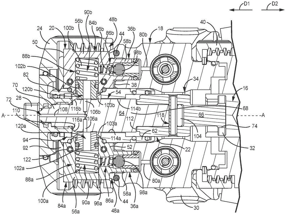
图2A是沿图1A中的线2-2截取的多部件式喷涂器10的截面图。图2B是图2A中的细节Z的放大图。图2A和图2B将被一起论述。致动器16、安装头部18、流体盒20、混合腔组件22、保持帽24、空气帽28、以及歧管30。致动器16包括突片锁定部32。示出了安装头部18的中心孔34、物料端口36a、36b;腔壁38;头部连接器40;销44;狭槽48a、48b;以及物料通道80a、80b。示出了流体盒20的第一端50,第二端52,盒孔54,突出部56a、56b;流体柱58a、58b;中心延伸部62;混合器主体82;密封壳体84a、84b;流体止回件86a、86b;侧部密封件88a、88b;物料通路90a、90b;盒盖92;吹扫腔94;以及保持构件103a、103b。流体止回件86a、86b分别包括弹簧96a、96b和滚珠98a、98b。侧部密封件88a、88b分别包括侧部弹簧100a、100b和密封构件102a、102b。密封构件102a、102b分别包括密封通道120a、120b。混合腔组件22包括混合腔64和腔连接器66。示出了混合腔64的主体68,头部70,喷涂孔口72,尾部104,入口孔106a、106b;以及混合孔108。主体68包括第一主体端110,第二主体端112,横向侧面114a、114b,以及斜面116a、116b。尾部104包括销孔118。腔连接器66包括锁定突片74。2A is a cross-sectional view of the multi-component sprayer 10 taken along line 2-2 in FIG. 1A. Figure 2B is an enlarged view of detail Z in Figure 2A. Figures 2A and 2B will be discussed together. Actuator 16 , mounting head 18 , fluid box 20 , mixing chamber assembly 22 , retaining cap 24 , air cap 28 , and manifold 30 . The actuator 16 includes a tab lock 32 . Shown are central bore 34 of mounting head 18, material ports 36a, 36b; cavity wall 38; head connector 40; pin 44; slots 48a, 48b; Shown are first end 50, second end 52, cartridge bore 54, protrusions 56a, 56b of fluid cartridge 20; fluid columns 58a, 58b; central extension 62; mixer body 82; seal housings 84a, 84b; Fluid checks 86a, 86b; side seals 88a, 88b; material passages 90a, 90b; lid 92; purge chamber 94; Fluid checks 86a, 86b include springs 96a, 96b and balls 98a, 98b, respectively. Side seals 88a, 88b include side springs 100a, 100b and seal members 102a, 102b, respectively. The sealing members 102a, 102b include sealing channels 120a, 120b, respectively. The mixing chamber assembly 22 includes a mixing chamber 64 and a chamber connector 66 . Main body 68 of mixing chamber 64 , head 70 , spray orifice 72 , tail 104 , inlet holes 106 a , 106 b ; and mixing hole 108 are shown. The body 68 includes a first body end 110, a second body end 112, lateral sides 114a, 114b, and beveled surfaces 116a, 116b. Tail 104 includes pin hole 118 . Cavity connector 66 includes locking tabs 74 .

安装头部18被安装至多部件式喷涂器10的主体。头部连接器40被能够转动地设置在安装头部18上。头部连接器40将安装头部18固定至多部件式喷涂器10。物料通道80a、80b延伸穿过安装头部18并分别将所述第一成分物料和第二成分物料从歧管30传输至物料端口36a、36b。物料端口36a、36b延伸到安装头部18的腔壁38中。中心孔34轴向地延伸穿过安装头部18。狭槽48a、48b被形成在安装头部18的接收部分42(图1B和图3A至图4B)中。狭槽48a、48b确保流体盒20在组装期间的适当的对准并防止流体盒20相对于安装头部18的转动,以帮助在组装和操作期间将流体盒20保持在适当的位置处。销44被设置在狭槽48a、48b的封闭端处。Mounting head 18 is mounted to the body of multi-component sprayer 10 . The head connector 40 is rotatably provided on the mounting head 18 . Head connector 40 secures mounting head 18 to multi-component sprayer 10 . Feed channels 80a, 80b extend through mounting head 18 and convey the first and second constituent materials from manifold 30 to feed ports 36a, 36b, respectively. The material ports 36a, 36b extend into a cavity wall 38 of the mounting head 18 . A central bore 34 extends axially through the mounting head 18 . Slots 48a, 48b are formed in the receiving portion 42 of the mounting head 18 ( FIGS. 1B and 3A-4B ). Slots 48a, 48b ensure proper alignment of fluid cartridge 20 during assembly and prevent rotation of fluid cartridge 20 relative to mounting head 18 to help hold fluid cartridge 20 in place during assembly and operation. Pins 44 are provided at the closed ends of the slots 48a, 48b.

流体盒20被流体地连接至安装头部18并被固定在所述接收部分42内。保持帽24被附接至安装头部18并且将流体盒20固定在所述头部腔46内。密封壳体84a、84b被设置在混合器主体82的相反侧上。突出部56a、56b由密封壳体84a、84b的多个部分来形成。突出部56a、56b被接收在狭槽48a、48b中。盒盖92在密封壳体84a、84b和混合器主体82的多个部分上延伸以将密封壳体84a、84b和混合器主体82固定在一起从而形成流体盒20。在一些示例中,盒盖92可以形成永久性连接,使得拆卸流体盒20将破坏形成流体盒20的一个或更多个零件的可操作性。在一些示例中,紧固件122(诸如销或螺旋)以及其它选择一起延伸穿过混合器主体82和密封壳体84a、84b以将混合器主体82和密封壳体84a、84b连结在一起。盒盖92可以覆盖紧固件122延伸穿过的开口。当流体盒20被描述为由分立的密封壳体84a、84b;混合器主体82;以及盒盖92形成时,应该理解,流体盒20可以形成为单一零件。例如,流体盒20可以通过模塑、铸造、增材制造、或任何其它适合的制造过程而形成。另外,在一些示例中,形成流体盒20的部件可以被永久地连结,使得拆卸所述部件会破坏流体盒20的可操作性。The fluid cartridge 20 is fluidly connected to the mounting head 18 and secured within the receiving portion 42 . Retaining cap 24 is attached to mounting head 18 and secures fluid cartridge 20 within said head cavity 46 . Sealed housings 84 a , 84 b are provided on opposite sides of the mixer body 82 . The protrusions 56a, 56b are formed by portions of the sealed housings 84a, 84b. The protrusions 56a, 56b are received in the slots 48a, 48b. A cartridge cover 92 extends over portions of the seal housings 84 a , 84 b and the mixer body 82 to secure the seal housings 84 a , 84 b and the mixer body 82 together to form the fluid cartridge 20 . In some examples, cartridge cover 92 may form a permanent connection such that removal of fluid cartridge 20 would disrupt operability of one or more parts forming fluid cartridge 20 . In some examples, fasteners 122 such as pins or screws extend together through the mixer body 82 and the seal housings 84a, 84b, among other options, to join the mixer body 82 and the seal housings 84a, 84b together. The lid 92 may cover the opening through which the fastener 122 extends. While fluid cartridge 20 is described as being formed from separate sealed housings 84a, 84b; mixer body 82; and cartridge cover 92, it should be understood that fluid cartridge 20 may be formed as a single piece. For example, fluid cartridge 20 may be formed by molding, casting, additive manufacturing, or any other suitable manufacturing process. Additionally, in some examples, the components forming fluid cartridge 20 may be permanently joined such that removal of the components disrupts the operability of fluid cartridge 20 .

物料通路90a、90b分别延伸穿过密封壳体84a、84b。物料通路90a、90b提供用于使所述第一成分物料和第二成分物料流过流体盒20到达中心孔34的流路。流体止回件86a、86b分别被设置在物料通路90a、90b的输入端处。流体柱58a、58b从流体盒20的第二端52突出并且被配置成分别延伸到物料端口36a、36b中。流体止回件86a、86b被设置在物料通路90a、90b的输入端处,并且在示出的示例中至少部分地设置在流体柱58a、58b中。滚珠98a、98b被设置在物料通路90a、90b中并且弹簧96a、96b与滚珠98a、98b界面地连接,以将滚珠98a、98b偏压到闭合位置处。每个流体止回件86a、86b的座位由附接至流体柱58a、58b的部件形成。所述座位部分可以以任何期望的方式,诸如压配合或螺纹连接、以及其它选择,被附接至流体柱58a、58b。流体止回件86a、86b防止流体回流离开流体盒20并进入安装头部18的物料通道80a、80b中。这样,流体止回件86a、86b保证任何窜流都不能流入到安装头部18中并污染所述安装头部18。Material passages 90a, 90b extend through seal housings 84a, 84b, respectively. The feed passages 90 a , 90 b provide a flow path for the first and second constituent feeds to flow through the fluid cartridge 20 to the central bore 34 . Fluid checks 86a, 86b are provided at the input ends of material passages 90a, 90b, respectively. Fluid columns 58a, 58b project from second end 52 of fluid cartridge 20 and are configured to extend into material ports 36a, 36b, respectively. A fluid check 86a, 86b is disposed at the input of the material passage 90a, 90b, and in the example shown at least partially within the fluid column 58a, 58b. Balls 98a, 98b are disposed in the material passages 90a, 90b and springs 96a, 96b interface with the balls 98a, 98b to bias the balls 98a, 98b into the closed position. The seat of each fluid check 86a, 86b is formed by a component attached to the fluid column 58a, 58b. The seat portion may be attached to the fluid columns 58a, 58b in any desired manner, such as a press fit or threaded connection, among other options. The fluid checks 86 a , 86 b prevent backflow of fluid out of the fluid cartridge 20 and into the material channels 80 a , 80 b of the mounting head 18 . In this way, the fluid checks 86a, 86b ensure that any channeling cannot flow into the mounting head 18 and contaminate said mounting head 18 .

侧部密封件88a、88b分别被至少部分地设置在物料通路90a、90b中。侧部弹簧100a、100b被设置在物料通路90a、90b中并朝向轴线A-A偏压密封构件102a、102b。密封构件102a、102b包括用于与混合腔64的平坦的横向侧面114a、114b接合和密封的平坦的面。密封构件102a、102b向入口孔106a、106b提供所述成分物料。密封构件102a、102b包括密封通道120a、120b,所述成分物料流过所述密封通道120a、120b。侧部密封件88a、88b被预加载,这意味着侧部弹簧100a、100b向密封构件102a、102b施加力,以在安装混合腔组件22之前将密封构件102a、102b偏压到盒孔54中。密封构件102a、102b部分地突出离开物料通路90a、90b并进入盒孔54中。保持构件103a、103b(诸如夹子)在物料通路90a、90b中被设置在盒孔54附近并与密封构件102a、102b界面地连接,以将密封构件102a、102b保持在物料通路90a、90b中并限制密封构件102a、102b可以突入到盒孔54中的程度。密封构件102a、102b在安装混合腔组件22之前突入到盒孔54中,以确保密封构件102a、102b与横向侧面114a、114b之间的适当的接合以及密封。Side seals 88a, 88b are at least partially disposed within material passages 90a, 90b, respectively. Side springs 100a, 100b are disposed in the material passages 90a, 90b and bias the sealing members 102a, 102b towards the axis A-A. The sealing members 102 a , 102 b include planar faces for engaging and sealing with the planar lateral sides 114 a , 114 b of the mixing chamber 64 . The sealing members 102a, 102b provide the constituent material to the inlet apertures 106a, 106b. The sealing member 102a, 102b includes a sealing channel 120a, 120b through which the constituent material flows. The side seals 88a, 88b are preloaded, which means that the side springs 100a, 100b apply a force to the seal members 102a, 102b to bias the seal members 102a, 102b into the cartridge bore 54 prior to installation of the mixing chamber assembly 22 . The sealing members 102 a , 102 b partially protrude out of the material passages 90 a , 90 b and into the cassette bore 54 . A retaining member 103a, 103b, such as a clip, is disposed in the mass passage 90a, 90b adjacent the cartridge aperture 54 and interfaces with the sealing member 102a, 102b to retain the sealing member 102a, 102b in the mass passage 90a, 90b and The extent to which the sealing members 102a, 102b can protrude into the cartridge hole 54 is limited. The sealing members 102a, 102b protrude into the box bore 54 prior to installation of the mixing chamber assembly 22 to ensure proper engagement and sealing between the sealing members 102a, 102b and the lateral sides 114a, 114b.

中心延伸部62由混合器主体82的延伸超过流体盒20的第二端52的一部分形成。中心延伸部62延伸到安装头部18的盒孔54中。盒孔54轴向地延伸穿过混合腔64。吹扫腔94被形成在盒孔54的一部分中。混合腔64被设置在盒孔54中且能沿轴线A-A移动。The central extension 62 is formed by a portion of the mixer body 82 that extends beyond the second end 52 of the fluid cartridge 20 . The central extension 62 extends into the box bore 54 of the mounting head 18 . The box bore 54 extends axially through the mixing chamber 64 . A purge chamber 94 is formed in a portion of the cartridge bore 54 . A mixing chamber 64 is disposed in the cassette bore 54 and is movable along axis A-A.

混合腔组件22被设置在轴线A-A上。混合腔组件22被附接至致动器16以沿轴线A-A移动。混合腔组件22接收所述第一成分物料和第二成分物料。所述多成分物料被形成在混合腔组件22中且从形成在混合腔64中的喷涂孔口72喷出。腔连接器66通过延伸穿过腔连接器66和销孔118的销而被安装至尾部104。然而,应该理解,所述腔连接器66可以以诸如通过接口螺纹以及其它选择的任何期望的方式被附接至混合腔64。锁定突片74被设置在腔连接器66的与混合腔64相反的端部处。锁定突片74被突片锁定部32接收以将混合腔组件22固定至致动器16。The mixing chamber assembly 22 is arranged on the axis A-A. Mixing chamber assembly 22 is attached to actuator 16 for movement along axis A-A. Mixing chamber assembly 22 receives the first and second component materials. The multi-component material is formed in the mixing chamber assembly 22 and is sprayed from a spraying orifice 72 formed in the mixing chamber 64 . The cavity connector 66 is mounted to the tail 104 by a pin extending through the cavity connector 66 and the pin hole 118 . It should be understood, however, that the chamber connector 66 may be attached to the mixing chamber 64 in any desired manner, such as by interface threads, among other options. A locking tab 74 is provided at the end of the cavity connector 66 opposite the mixing cavity 64 . The locking tab 74 is received by the tab lock 32 to secure the mixing chamber assembly 22 to the actuator 16 .

盒主体68在第一主体端110与第二主体端112之间延伸。头部70从第一主体端110突出。空气帽28被安装在头部70上且可以以任何期望的方式被附接至头部70。例如,头部70和空气帽28可以包括接口螺纹以及其它选择。尾部104从第二主体端112延伸。销孔118通过尾部104突出。The cartridge body 68 extends between a first body end 110 and a second body end 112 . Head 70 protrudes from first body end 110 . The air cap 28 is mounted on the head 70 and may be attached to the head 70 in any desired manner. For example, head 70 and air cap 28 may include interface threads, among other options. The tail portion 104 extends from the second body end 112 . A pin hole 118 protrudes through tail 104 .

横向侧面114a、114b在第一主体端110与第二主体端112之间延伸。横向侧面114a、114b形成平坦的轴向面,所述平坦的轴向面促进密封构件102a、102b与横向侧面114a、114b之间的滑动接合。斜面116a、116b形成第一端50与第二端52之间的过渡部。斜面116a、116b促进混合腔64的安装,所述混合腔64从第二端52且沿方向D1被插入到盒孔54中。斜面116a、116b接合密封构件102a、102b并推动密封构件102a、102b远离轴线A-A,以加宽密封构件102a、102b之间的间隙并允许混合腔64在密封构件102a、102b下方行进,使得密封构件102a、102b行进到横向侧面114a、114b上并与横向侧面114a、114b接合。斜面116a、116b形成混合腔64的过渡特征部,所述过渡特征部促进通过预加载侧部密封件88a、88b而进行的混合腔64的安装。The lateral sides 114a, 114b extend between the first body end 110 and the second body end 112 . The lateral sides 114a, 114b form planar axial faces that facilitate sliding engagement between the sealing members 102a, 102b and the lateral sides 114a, 114b. The ramps 116 a , 116 b form a transition between the first end 50 and the second end 52 . The ramps 116a, 116b facilitate the installation of the mixing chamber 64 which is inserted into the cartridge bore 54 from the second end 52 and in the direction D1. The ramps 116a, 116b engage the sealing members 102a, 102b and push the sealing members 102a, 102b away from the axis A-A to widen the gap between the sealing members 102a, 102b and allow the mixing chamber 64 to travel under the sealing members 102a, 102b such that the sealing members 102a, 102b travel onto and engage lateral sides 114a, 114b. The ramps 116a, 116b form transition features of the mixing chamber 64 that facilitate installation of the mixing chamber 64 by preloading the side seals 88a, 88b.

入口孔106a、106b分别延伸到横向侧面114a、114b中并穿过主体68到达混合孔108。在一些示例中,入口孔106a、106b径向地延伸穿过主体68。然而,应该理解,所述入口孔106a、106b可以被设置成处于提供至混合孔108的流体流路的、相对于轴线A-A的任何期望的定向。混合孔108在入口孔106a、106b与喷涂孔口72之间延伸穿过混合腔64。混合孔108从入口孔106a、106b接收流体并将所述流体提供至喷涂孔口72。混合腔64沿轴线A-A在与所述喷涂状态相关联的第一位置和与所述吹扫状态相关联的第二位置之间移动,在所述第一位置处混合腔64从入口孔106a、106b接收单独的成分物料并将所产生的多成分物料提供至喷涂孔口72,在所述第二位置处混合腔从入口孔106a、106b接收吹扫空气并将所述吹扫空气提供至喷涂孔口72。The inlet holes 106 a , 106 b extend into the lateral sides 114 a , 114 b respectively and through the main body 68 to the mixing hole 108 . In some examples, the inlet holes 106 a , 106 b extend radially through the body 68 . It should be understood, however, that the inlet holes 106a, 106b may be arranged in any desired orientation relative to the axis A-A of the fluid flow path provided to the mixing hole 108 . A mixing hole 108 extends through the mixing chamber 64 between the inlet holes 106 a , 106 b and the spraying orifice 72 . The mixing hole 108 receives fluid from the inlet holes 106 a , 106 b and provides the fluid to the spray orifice 72 . The mixing chamber 64 moves along the axis A-A between a first position associated with the spraying state and a second position associated with the purging state, in which the mixing chamber 64 passes from the inlet hole 106a, 106b receives the individual component feeds and provides the resulting multi-component feed to the spray orifice 72, at which the mixing chamber receives purge air from the inlet holes 106a, 106b and provides the purge air to the spray orifice 72. Orifice 72.

混合腔组件22、安装头部18和流体盒20能从多部件式喷涂器10移除。在组装期间,混合腔组件22被安装至致动器16。锁定突片74被插入突片锁定部32中并被转动以将锁定突片74固定至致动器16。安装头部18沿方向D2被轴向地移动使得混合腔64行进穿过中心孔34。头部连接器40被固定至枪主体68。Mixing chamber assembly 22 , mounting head 18 and fluid cartridge 20 are removable from multi-component sprayer 10 . During assembly, mixing chamber assembly 22 is mounted to actuator 16 . The locking tab 74 is inserted into the tab lock 32 and turned to secure the locking tab 74 to the actuator 16 . Mounting head 18 is moved axially in direction D2 such that mixing chamber 64 travels through central bore 34 . The head connector 40 is secured to the gun body 68 .

流体盒20沿方向D2被轴向地移动并被移动到安装头部18上。流体柱58a、58b延伸到物料端口36a、36b中并被所述物料端口36a、36b接收,由此形成安装头部18与流体盒20之间的流体和机械连接。中心延伸部62延伸到中心孔34中并被所述中心孔34接收。突出部56a、56b由狭槽48a、48b接收,从而在流体盒20被移动到安装头部18上的位置处时促进流体盒20与安装头部18的适当的对准。The fluid cartridge 20 is moved axially in direction D2 and onto the mounting head 18 . Fluid columns 58 a , 58 b extend into and are received by material ports 36 a , 36 b , thereby forming a fluid and mechanical connection between mounting head 18 and fluid cartridge 20 . The central extension 62 extends into and is received by the central bore 34 . The protrusions 56a, 56b are received by the slots 48a, 48b to facilitate proper alignment of the fluid cartridge 20 with the mounting head 18 as the fluid cartridge 20 is moved into position on the mounting head 18 .

当流体盒20沿方向D2移动时,混合腔64行进穿过盒孔54。斜面116a、116b是混合腔64的用于与密封构件102a、102b接触的第一部分。斜面116a、116b形成推动密封构件102a、102b远离轴线A-A的倾斜过渡特征部,从而在混合腔64行进穿过盒孔54时加宽密封构件102a、102b之间的间隙。横向侧面114a、114b在密封构件102a、102b下方行进并被密封构件102a、102b密封地接合。密封构件102a、102b形成在整个操作期间保持与横向侧面114a、114b接合的滑动密封件。As fluid cartridge 20 is moved in direction D2 , mixing chamber 64 travels through cartridge bore 54 . The ramps 116a, 116b are the first portion of the mixing chamber 64 for contacting the sealing members 102a, 102b. The ramps 116a, 116b form sloped transition features that push the sealing members 102a, 102b away from the axis A-A, thereby widening the gap between the sealing members 102a, 102b as the mixing chamber 64 travels through the cartridge bore 54. The lateral sides 114a, 114b run below and are sealingly engaged by the sealing members 102a, 102b. The sealing members 102a, 102b form sliding seals that remain engaged with the lateral sides 114a, 114b throughout operation.

盒盖92被附接至安装头部18以将流体盒20固定在安装头部18上的适当的位置处。空气帽28被附接至头部70。歧管30被附接至安装头部18。多部件式喷涂器10因而准备好操作。尽管安装头部18和流体盒20被描述为单独形成的部件,但是应该理解,安装头部18和流体盒20可以被永久地附接或被整体形成,使得安装头部18和流体盒20形成可移除的安装和混合组件。A cartridge cover 92 is attached to the mounting head 18 to secure the fluid cartridge 20 in place on the mounting head 18 . Air cap 28 is attached to head 70 . A manifold 30 is attached to the mounting head 18 . The multi-component sprayer 10 is thus ready for operation. Although mounting head 18 and fluid cartridge 20 are described as separately formed components, it should be understood that mounting head 18 and fluid cartridge 20 may be permanently attached or integrally formed such that mounting head 18 and fluid cartridge 20 form Removable mounting and mixing components.

流体盒20促进流体密封部件(诸如侧部密封件88a、88b)的快速且容易的更换,由此减少在操作期间的停机时间。另外,流体盒20将所述流体密封部件合并成单个组件,由此将更换零件的数目减小至一个,从而进一步减少停机时间并提高生产率。为了更换流体盒20,使用者移除空气帽28和盒盖92。流体盒20沿方向D1被轴向地拉动,从而从物料端口36a、36b移除流体柱58a、58b并从中心孔34移除中心延伸部62。流体盒20沿方向D2移动通过盒孔54并被从盒孔54移除。新的流体盒20可以随后如上文所论述的那样被安装。多部件式喷涂器10准备好用于喷涂。Fluid cartridge 20 facilitates quick and easy replacement of fluid-tight components, such as side seals 88a, 88b, thereby reducing downtime during operation. Additionally, the fluid cartridge 20 consolidates the fluid sealing components into a single assembly, thereby reducing the number of replacement parts to one, further reducing downtime and increasing productivity. To replace fluid cartridge 20 , the user removes air cap 28 and cartridge cover 92 . Fluid cartridge 20 is pulled axially in direction D1 , removing fluid columns 58 a , 58 b from material ports 36 a , 36 b and central extension 62 from central bore 34 . Fluid cartridge 20 is moved in direction D2 through and removed from cartridge aperture 54 . A new fluid cartridge 20 can then be installed as discussed above. The multi-part applicator 10 is ready for spraying.

如果需要新的混合腔64,则安装头部18可以与枪主体68断开连接并沿方向D1拉动离开混合腔64。歧管30可以在折卸期间保持连接至安装头部18。混合腔组件22被转动并沿方向D1被拉动以从突片锁定部32移除锁定突片74。新的混合腔64组件可以被附接在突片锁定部32处并且安装头部18和流体盒20可以如上文所论述的那样被安装。在一些示例中,所述销可以被从销孔118拉动,由此将腔连接器66与混合腔64断开连接。新的混合腔64可以被附接至腔连接器66以形成新的混合腔组件22。在一些示例中,使用者可以更换具有不同的喷涂孔口结构的不同的混合腔组件22以提供不同的喷涂模式。混合腔组件22促进多部件式喷涂器10的所述流体处理部件的容易的移除和更换。If a new mixing chamber 64 is required, the mounting head 18 can be disconnected from the gun body 68 and pulled away from the mixing chamber 64 in direction D1. Manifold 30 may remain connected to mounting head 18 during disassembly. Mixing chamber assembly 22 is rotated and pulled in direction D1 to remove locking tab 74 from tab locking portion 32 . A new mixing chamber 64 assembly can be attached at the tab lock 32 and the mounting head 18 and fluid cartridge 20 can be installed as discussed above. In some examples, the pin may be pulled from pin hole 118 , thereby disconnecting chamber connector 66 from mixing chamber 64 . A new mixing chamber 64 may be attached to chamber connector 66 to form new mixing chamber assembly 22 . In some examples, a user may swap out a different mixing chamber assembly 22 having a different spray orifice configuration to provide a different spray pattern. The mixing chamber assembly 22 facilitates easy removal and replacement of the fluid handling components of the multi-component sprayer 10 .

在操作期间,致动器16沿方向D1被驱动以停止所述多成分物料的喷涂并且沿方向D2被驱动以启动所述多成分物料的喷涂。然而,应该理解,所述多部件式喷涂器10可以被配置成使得致动器16沿方向D1被驱动以启动喷涂并且沿方向D2被驱动以停止喷涂。例如,混合腔64可以被配置成使得在混合腔64处于所述吹扫状态的情况下,入口孔106a、106b被设置在密封构件102a、102b的与喷涂孔口72相反的一侧上。During operation, the actuator 16 is driven in direction D1 to stop the spraying of the multi-component material and in direction D2 to start the spraying of the multi-component material. However, it should be understood that the multi-component sprayer 10 may be configured such that the actuator 16 is driven in direction D1 to start spraying and in direction D2 to stop spraying. For example, the mixing chamber 64 may be configured such that the inlet apertures 106a, 106b are disposed on the opposite side of the sealing member 102a, 102b from the spraying orifice 72 when the mixing chamber 64 is in the purged state.

致动器16和混合腔组件22在图2A和图2B中被示出为处于所述喷涂状态。最初,混合腔组件22处于第一位置,在所述第一位置处,入口孔106a、106b沿方向D1相对于密封构件102a、102b移动,使得入口孔106a、106b位于密封构件102a、102b前方并通过密封构件102a、102b与物料通路90a、90b流体地隔离。在所述第一位置处,入口孔106a、106b被定位在吹扫腔94中以接收吹扫空气,如下文关于图3A和图3B进一步论述的。所述吹扫空气流过入口孔106a、106b和混合孔108并流出喷涂孔口72。在一些示例中,所述吹扫空气不断地流动至吹扫腔94,并且因此当混合腔64处于所述吹扫状态时流过混合腔64。所述吹扫空气将残留在混合腔64中的任何成分物料通过喷涂孔口72吹出混合腔64,从而防止在混合腔64中固化并保持混合腔64的可操作性。The actuator 16 and mixing chamber assembly 22 are shown in the spraying state in FIGS. 2A and 2B . Initially, the mixing chamber assembly 22 is in a first position in which the inlet apertures 106a, 106b are moved in direction D1 relative to the sealing members 102a, 102b such that the inlet apertures 106a, 106b are in front of the sealing members 102a, 102b and The material passages 90a, 90b are fluidly isolated by sealing members 102a, 102b. In the first position, the inlet holes 106a, 106b are positioned in the purge cavity 94 to receive purge air, as discussed further below with respect to FIGS. 3A and 3B . The purge air flows through the inlet holes 106 a , 106 b and the mixing hole 108 and out of the spray orifice 72 . In some examples, the purge air is continuously flowing to purge chamber 94 and thus flows through mixing chamber 64 when mixing chamber 64 is in the purge state. The purge air blows any component material remaining in the mixing chamber 64 out of the mixing chamber 64 through the spray orifice 72 , thereby preventing solidification in the mixing chamber 64 and maintaining the operability of the mixing chamber 64 .

所述第一成分物料进入安装头部18中并且流过物料通道80a到达物料端口36a。所述第一成分物料的上游压力使流体止回件86a打开并驱动所述第一成分物料通过流体止回件86a。所述第一成分物料流过物料通路90a和密封构件102a并且紧紧地抵住横向侧面114a。所述上游压力推动密封构件102a与横向侧面114a接合,从而加强了形成在所述密封构件102a与所述横向侧面114a之间的密封。在示出的示例中,密封构件102a形成横向侧面114a上的环状密封。当混合腔64移动位置时,侧部密封件88a进一步擦拭横向侧面114a,以防止任何第一成分物料的残余物残留在横向侧面114a上,所述物料可能在横向侧面114a上固化并损坏密封构件102a。The first component material enters the mounting head 18 and flows through the material channel 80a to the material port 36a. Upstream pressure of the first component material opens fluid check 86a and drives the first component through fluid check 86a. The first component material flows through the material passage 90a and the sealing member 102a and tightly against the lateral side 114a. The upstream pressure urges the sealing member 102a into engagement with the lateral side 114a, thereby strengthening the seal formed between the sealing member 102a and the lateral side 114a. In the example shown, the sealing member 102a forms an annular seal on the lateral side 114a. As the mixing chamber 64 shifts position, the side seals 88a further wipe the lateral sides 114a to prevent residues of any first component material from remaining on the lateral sides 114a, which could solidify on the lateral sides 114a and damage the sealing member. 102a.

所述第二成分物料进入安装头部18中并且流过物料通道80b到达物料端口36b。所述第二成分物料的上游压力使流体止回件86b打开并驱动所述第二成分物料通过流体止回件86b。所述第二成分物料流过物料通路90b和密封构件102a并且紧紧抵住横向侧面114b。所述上游压力进一步推动密封构件102b与横向侧面114b接合,从而加强了形成在所述密封构件102b与所述横向侧面114b之间的密封。在示出的示例中,密封构件102b形成横向侧面114b上的环状密封。当混合腔64移动位置时,侧部密封件88b擦拭横向侧面114b,以防止任何第二成分物料的残余物残留在横向侧面114b上,所述物料可能在横向侧面114b上固化并损坏密封构件102b。The second component material enters the mounting head 18 and flows through the material channel 80b to the material port 36b. Upstream pressure of the second constituent material opens fluid check 86b and drives the second constituent through fluid check 86b. The second component material flows through the material passage 90b and the sealing member 102a and tightly against the lateral side 114b. The upstream pressure further urges the sealing member 102b into engagement with the lateral side 114b, thereby strengthening the seal formed between the sealing member 102b and the lateral side 114b. In the example shown, the sealing member 102b forms an annular seal on the lateral side 114b. As the mixing chamber 64 shifts position, the side seals 88b wipe the lateral sides 114b to prevent residues of any second component material from remaining on the lateral sides 114b, which could solidify on the lateral sides 114b and damage the sealing member 102b. .

为了启动喷涂,致动器16沿方向D2被驱动。致动器16沿方向D2拉动混合腔组件22并进入所述喷涂状态。入口孔106a、106b在密封构件102a、102b下方行进并与物料通路90a、90b流体连通。物料通路90a中的上游压力驱动所述第一成分物料通过入口孔106a到达混合孔108。物料通路90b中的上游压力驱动所述第二成分物料通过入口孔106b到达混合孔108。所述第一成分物料和第二成分物料在混合孔108中结合以形成所述多成分物料。所述多成分物料作为喷剂被喷射通过喷涂孔口72。To start spraying, the actuator 16 is driven in direction D2. Actuator 16 pulls mixing chamber assembly 22 in direction D2 and enters the spraying state. The inlet apertures 106a, 106b run below the sealing members 102a, 102b and are in fluid communication with the material passages 90a, 90b. Upstream pressure in feed passage 90a drives the first component feed through inlet orifice 106a to mixing orifice 108 . Upstream pressure in feed passage 90b drives the second component feed through inlet orifice 106b to mixing orifice 108 . The first component material and the second component material are combined in mixing holes 108 to form the multi-component material. The multi-component material is injected through the spray orifice 72 as a spray.

为了停止喷涂,致动器16沿方向D2被驱动。致动器16沿方向D1推动混合腔组件22进入所述吹扫状态。入口孔106a、106b在密封构件102a、102b下方行进并与物料通路90a、90b脱离流体连通。所述吹扫空气流过入口孔106a、106b和混合孔108并将在入口孔106a、106b和混合孔108中剩余的物料吹出喷涂孔口72。To stop spraying, the actuator 16 is driven in direction D2. Actuator 16 urges mixing chamber assembly 22 in direction D1 into the purged state. The inlet holes 106a, 106b run below the sealing members 102a, 102b and are out of fluid communication with the material passages 90a, 90b. The purge air flows through the inlet holes 106 a , 106 b and the mixing hole 108 and blows the material remaining in the inlet holes 106 a , 106 b and the mixing hole 108 out of the spraying orifice 72 .

在一些情况下,所述第一成分物料或第二成分物料可能窜流到相反的物料通道80a、80b中,从而导致在所述部位处的固化。例如,在所述第一成分物料和第二成分物料的上游压力不平衡时可能发生这样的窜流。流体止回件86a、86b防止这样的窜流离开流体盒20。这样,所述窜流和污染物被包含在流体盒20内。流体止回件86a、86b防止安装头部18在窜流的情况下被污染。如上文所论述的,流体盒20可以被容易地移除且新的流体盒20可以被容易地安装以使多部件式喷涂器10恢复操作。In some cases, the first or second component material may channel into the opposing material channels 80a, 80b, causing solidification at that location. Such channeling may occur, for example, when there is an imbalance in the upstream pressures of the first and second constituent materials. Fluid checks 86 a , 86 b prevent such channeling away from fluid cartridge 20 . In this way, the cross-flow and contaminants are contained within the fluid cartridge 20 . The fluid checks 86a, 86b prevent contamination of the mounting head 18 in the event of channeling. As discussed above, the fluid cartridge 20 can be easily removed and a new fluid cartridge 20 can be easily installed to return the multi-part applicator 10 to operation.

多部件式喷涂器10提供显著的优点。流体盒20促进可以被窜流污染的所述流体处理部件的快速且简单的更换。流体盒20提供单个更换零件,从而减少使用者的零件的数量和库存、减少停机时间并增加操作效率。混合腔64通过被预加载的侧部密封件88a、88b促进在流体盒20内的的安装。混合腔组件22可以被容易地附接至致动器16并从致动器16分离,从而促进快速更换、减少停机时间并增加操作效率。The multi-component sprayer 10 offers significant advantages. The fluid cassette 20 facilitates quick and simple replacement of said fluid treatment components that may be contaminated by channeling. Fluid cartridge 20 provides a single replacement part, thereby reducing the number and inventory of parts for the user, reducing downtime and increasing operational efficiency. The mixing chamber 64 facilitates installation within the fluid cartridge 20 by preloaded side seals 88a, 88b. The mixing chamber assembly 22 can be easily attached and detached from the actuator 16, facilitating quick replacement, reducing downtime, and increasing operational efficiency.

图3A是沿图1A中的线3-3截取的多部件式喷涂器10的截面图。图3B是图3A中的细节Y的放大图。图3A和图3B将被一起论述。多部件式喷涂器10包括手柄12;扳机14;致动器16;安装头部18;流体盒20;混合腔组件22;保持帽24;空气帽28;歧管30;控制阀124(图3A);空气入口126(图3A);空气排出口128(图3A);控制路径130a、130b(图3A);以及吹扫空气路径132。致动器16包括突片锁定部32。示出了安装头部18的中心孔34、头部连接器40、腔壁38、接收部分42、吹扫孔134、吹扫端口136、以及紧固件孔138。接收部分42限定头部腔46。示出了流体盒20的第一端50、第二端52、盒孔54、吹扫柱60、中心延伸部62、混合器主体82、流体止回件86c、盒盖92、吹扫腔94、吹扫路径140、以及定位销142。流体止回件86c包括弹簧96c和滚珠98c。混合腔组件22包括混合腔64和腔连接器66。示出了混合腔64的主体68、头部70、喷涂孔口72、尾部104、以及入口孔106。主体68包括第一主体端110、第二主体端112、以及狭槽144。尾部104包括销孔118。腔连接器66包括锁定突片74。3A is a cross-sectional view of the multi-component sprayer 10 taken along line 3-3 in FIG. 1A. Figure 3B is an enlarged view of detail Y in Figure 3A. Figures 3A and 3B will be discussed together. Multi-part sprayer 10 includes handle 12; trigger 14; actuator 16; mounting head 18; fluid cartridge 20; mixing chamber assembly 22; retaining cap 24; air cap 28; manifold 30; ); air inlet 126 ( FIG. 3A ); air outlet 128 ( FIG. 3A ); control paths 130a, 130b ( FIG. 3A ); and purge air path 132 . The actuator 16 includes a tab lock 32 . Central bore 34 of mounting head 18 , header connector 40 , cavity wall 38 , receiving portion 42 , purge hole 134 , purge port 136 , and fastener hole 138 are shown. The receiving portion 42 defines a head cavity 46 . Shown are first end 50, second end 52, cartridge bore 54, purge post 60, central extension 62, mixer body 82, fluid check 86c, cartridge cover 92, purge chamber 94 of fluid cartridge 20 , a purge path 140 , and a positioning pin 142 . Fluid check 86c includes a spring 96c and a ball 98c. The mixing chamber assembly 22 includes a mixing chamber 64 and a chamber connector 66 . Main body 68 , head 70 , spray orifice 72 , tail 104 , and inlet orifice 106 of mixing chamber 64 are shown. The body 68 includes a first body end 110 , a second body end 112 , and a slot 144 . Tail 104 includes pin hole 118 . Cavity connector 66 includes locking tabs 74 .

空气入口126延伸到多部件式喷涂器10中并且被配置成接收从压缩空气来源(未示出)(诸如空气压缩机或空气罐)延伸的供气管线(未示出)。空气入口126提供用于压缩空气进入多部件式喷涂器10中的通路。多个空气入口126提供所述供气管线的替代连接点。未使用的所述空气入口126可以被塞住。空气入口126延伸至控制阀124。空气排出口128从控制阀124延伸通过手柄12。空气排出口128提供用于使压缩空气从多部件式喷涂器10排出的通路。Air inlet 126 extends into multi-component sprayer 10 and is configured to receive an air supply line (not shown) extending from a compressed air source (not shown), such as an air compressor or an air tank. Air inlet 126 provides access for compressed air to enter multi-component sprayer 10 . A plurality of air inlets 126 provide alternative connection points for the air supply line. The air inlets 126 that are not used may be plugged. Air inlet 126 extends to control valve 124 . An air outlet 128 extends from the control valve 124 through the handle 12 . An air discharge port 128 provides a passage for compressed air to exit the multi-component sprayer 10 .

致动器16被设置在多部件式喷涂器10中并且被配置成在所述喷涂状态与所述吹扫状态之间致动混合腔64,在所述喷涂状态中,混合腔64被定位成接收所述第一成分物料和第二成分物料并从喷涂孔口72喷射所述多成分物料,在所述吹扫状态中,混合腔64与所述第一成分物料和第二成分物料流体地断开连接并被替代地定位成从吹扫腔94接收吹扫空气。在示出的示例中,致动器16是气动活塞。Actuator 16 is provided in multi-part sprayer 10 and is configured to actuate mixing chamber 64 between the spraying state and the purge state, in which mixing chamber 64 is positioned to receiving the first and second component materials and spraying the multi-component material from spray orifice 72, in the purging state, mixing chamber 64 is in fluid communication with the first and second component materials is disconnected and is instead positioned to receive purge air from purge chamber 94 . In the example shown, the actuator 16 is a pneumatic piston.

控制阀124被设置在多部件式喷涂器10中并且控制通过控制路径130a、130b流至致动器16和来自致动器16的空气的流量。扳机14被可枢转地连接至多部件式喷涂器10并且在第一位置与第二位置之间致动控制阀124,在所述第一位置处,控制阀124引导压缩空气从空气入口126经由控制路径130a流至致动器16并引导用过的压缩空气从致动器16经由控制路径130b流至空气排出口128,在所述第二位置处,控制阀124引导压缩空气从空气入口126经由控制路径130b流至致动器16并且引导用过的压缩空气从致动器16经由控制路径130a流至空气排出口128。经由控制路径130a引导所述压缩空气会沿方向D2驱动致动器16并且因此驱动混合腔组件22,以将混合腔组件22放置在所述喷涂状态,使得混合腔64接收第一成分流体和第二成分流体。经由控制路径130b引导所述压缩空气会沿方向D1驱动致动器16并且因此驱动混合腔组件22以使混合腔组件22与第一成分流体流和第二成分流体流流体地断开连接并将混合腔组件22放置在所述吹扫状态。A control valve 124 is provided in the multi-component sprayer 10 and controls the flow of air to and from the actuator 16 through the control paths 130a, 130b. Trigger 14 is pivotally connected to multi-component sprayer 10 and actuates control valve 124 between a first position and a second position in which control valve 124 directs compressed air from air inlet 126 via Control path 130a flows to actuator 16 and directs used compressed air from actuator 16 to air exhaust 128 via control path 130b, in the second position control valve 124 directs compressed air from air inlet 126 Flows to the actuator 16 via the control path 130b and directs spent compressed air from the actuator 16 to the air discharge port 128 via the control path 130a. Directing the compressed air via control path 130a drives actuator 16 and thus mixing chamber assembly 22 in direction D2 to place mixing chamber assembly 22 in the spray state such that mixing chamber 64 receives the first component fluid and the second component fluid. Two component fluid. Directing the compressed air via control path 130b drives actuator 16 and thus mixing chamber assembly 22 in direction D1 to fluidly disconnect mixing chamber assembly 22 from the first and second constituent fluid streams and The mixing chamber assembly 22 is placed in the purged state.

吹扫空气路径132从控制阀124延伸至安装头部18中的吹扫端口136。吹扫空气路径132被不断地连接至经由空气入口126进入多部件式喷涂器10中的压缩空气流。所述吹扫空气是所述压缩空气的经由空气入口126提供的并通过吹扫空气路径132流至安装头部18的一部分。A purge air path 132 extends from the control valve 124 to a purge port 136 in the mounting head 18 . The purge air path 132 is continuously connected to the flow of compressed air entering the multi-component sprayer 10 via the air inlet 126 . The purge air is the portion of the compressed air that is provided via the air inlet 126 and flows through the purge air path 132 to the mounting head 18 .

安装头部18被安装至多部件式喷涂器10。安装头部18将安装头部18固定至枪主体68。在示出的示例中,头部连接器40和多部件式喷涂器10包括接口螺纹。歧管30被安装至安装头部18以将所述第一成分物料和第二成分物料提供至安装头部18。在示出的示例中,歧管紧固件146延伸到形成在安装头部18中的紧固件孔138中。然而,应该理解,所述歧管30可以以任何期望的方式被安装至安装头部18上。Mounting head 18 is mounted to multi-component sprayer 10 . The mounting head 18 secures the mounting head 18 to the gun body 68 . In the example shown, head connector 40 and multi-part applicator 10 include interface threads. A manifold 30 is mounted to the mounting head 18 to provide the first and second constituent materials to the mounting head 18 . In the example shown, the manifold fasteners 146 extend into fastener holes 138 formed in the mounting head 18 . However, it should be understood that the manifold 30 may be mounted to the mounting head 18 in any desired manner.

接收部分42从安装头部18的与头部连接器40相反的端部延伸。头部腔46由接收部分42来限定并且被配置成接收流体盒20。吹扫孔134延伸穿过安装头部18到达吹扫端口136。吹扫端口136延伸到腔壁38中。吹扫孔134从吹扫空气路径132接收吹扫空气。吹扫孔134向位于吹扫孔134处的流体盒20提供所述吹扫空气。A receiving portion 42 extends from the end of the mounting header 18 opposite the header connector 40 . Head cavity 46 is defined by receiving portion 42 and is configured to receive fluid cartridge 20 . A purge hole 134 extends through the mounting head 18 to a purge port 136 . The purge port 136 extends into the cavity wall 38 . Purge holes 134 receive purge air from purge air path 132 . The purge hole 134 provides the purge air to the fluid cartridge 20 located at the purge hole 134 .

流体盒20被设置在头部腔46中。中心延伸部62沿轴线A-A延伸并且突出超过流体盒20的第二端52。中心延伸部62由混合器主体82的延伸超过第二端52的一部分形成。中心延伸部62延伸到安装头部18的中心孔34中。盒孔54从第一端50延伸穿过流体盒20,并延伸穿过中心延伸部62。盒孔54接收混合腔64。混合腔64可以沿轴线A-A在盒孔54内轴向地移动。狭槽144被形成在主体68的底部中。狭槽144沿轴线A-A在第一主体端110与第二主体端112之间延伸。定位销142被安装至混合器主体82并且延伸到盒孔54中。定位销142被设置在狭槽144内并且当混合腔64在所述喷涂状态与吹扫状态之间变换时沿狭槽144滑动。与狭槽144界面地连接的定位销142会确保混合腔64的适当的安装和对准。因为定位销142将防止不正确地配置的混合腔64行进穿过盒孔54,所以定位销142和狭槽144确保混合腔64被正确地安装。另外,定位销142和狭槽144通过防止混合腔64被反向安装来提供防错措施。在一些示例中,尽管定位销142被示出与主体68单独地形成,但是应该理解,定位销142和主体68可以被形成为单个零件。尽管流体盒20被示出为包括定位销142,但是应该理解,流体盒20可以包括适于与狭槽144界面地连接的任何期望类型的突出部。例如,定位销142可以被形成为导轨或其它细长形的突出部、或被形成为一系列分立的突出部。Fluid cartridge 20 is disposed in head cavity 46 . The central extension 62 extends along the axis A-A and protrudes beyond the second end 52 of the fluid cartridge 20 . The central extension 62 is formed by a portion of the mixer body 82 that extends beyond the second end 52 . The central extension 62 extends into the central bore 34 of the mounting head 18 . A cartridge bore 54 extends from the first end 50 through the fluid cartridge 20 and through the central extension 62 . The box bore 54 receives a mixing chamber 64 . The mixing chamber 64 is axially movable within the cartridge bore 54 along the axis A-A. A slot 144 is formed in the bottom of the body 68 . The slot 144 extends along the axis A-A between the first body end 110 and the second body end 112 . Locating pins 142 are mounted to mixer body 82 and extend into box bore 54 . Locating pins 142 are disposed within slots 144 and slide along slots 144 as mixing chamber 64 transitions between the spray state and the purge state. Dowel pins 142 interfaced with slots 144 will ensure proper installation and alignment of mixing chamber 64 . The dowel pins 142 and the slots 144 ensure that the mixing chamber 64 is properly installed because the dowel pin 142 will prevent an incorrectly configured mixing chamber 64 from traveling through the cartridge aperture 54 . In addition, the alignment pin 142 and the slot 144 provide a measure of error-proofing by preventing the mixing chamber 64 from being installed backwards. In some examples, although the alignment pin 142 is shown as being formed separately from the body 68, it should be understood that the alignment pin 142 and the body 68 may be formed as a single piece. Although fluid cartridge 20 is shown as including alignment pins 142 , it should be understood that fluid cartridge 20 may include any desired type of protrusion suitable for interfacing with slot 144 . For example, the alignment pins 142 may be formed as rails or other elongated protrusions, or as a series of discrete protrusions.

吹扫柱60从第二端52突出。吹扫柱60延伸到安装头部18的吹扫孔134中。流体止回件86c被设置在流体盒20中并且被吹扫柱60保持在流体盒20内。在示出的示例中,吹扫柱60的一部分形成用于流体止回件86c的滚珠98的座位。弹簧96将滚珠98偏压到闭合位置处,使得滚珠98通常地座接于闭合位置。A purge column 60 protrudes from the second end 52 . The purge column 60 extends into the purge hole 134 of the mounting head 18 . Fluid check 86c is disposed in fluid box 20 and is retained within fluid box 20 by purge column 60 . In the example shown, a portion of purge post 60 forms a seat for ball 98 of fluid check 86c. Spring 96 biases ball 98 into the closed position such that ball 98 is normally seated in the closed position.

吹扫路径140从吹扫柱60穿过流体盒20延伸至盒孔54。吹扫路径140被配置成将吹扫空气提供至盒孔54的吹扫腔94。流体止回件86c允许在吹扫空气进入吹扫路径140的同时防止空气或物料从吹扫路径140回流到安装头部18中。例如,如果发生所述成分物料的窜流或其它渗漏,则所述成分物料可能流入吹扫路径140中。流体止回件86c防止所述物料从流体盒20回流到吹扫孔134中。这样,流体止回件86c保持安装头部18和多部件式喷涂器10内的空气路径免受物料污染。如果这样的污染确实发生于流体盒20中,则污染被限于流体盒20,使得使用者仅需要更换流体盒20而不是安装头部18或其它上游部件,以使多部件式喷涂器10恢复操作。尽管流体止回件86c被示出为球形止回阀,但是应该理解,流体止回件86c可以属于适于确保通过吹扫柱60的单向流的任何期望的结构。A purge path 140 extends from purge column 60 through fluid cartridge 20 to cartridge bore 54 . The purge path 140 is configured to provide purge air to the purge cavity 94 of the cartridge bore 54 . Fluid check 86c allows for the prevention of backflow of air or material from purge path 140 into mounting head 18 while purge air enters purge path 140 . For example, the constituent material may flow into purge path 140 if channeling or other leakage of the constituent material occurs. Fluid check 86c prevents backflow of the material from fluid cartridge 20 into purge hole 134 . In this way, fluid check 86c keeps the air path within mounting head 18 and multi-component applicator 10 free from material contamination. If such contamination does occur in the fluid cartridge 20, the contamination is confined to the fluid cartridge 20 so that the user only needs to replace the fluid cartridge 20 rather than install the head 18 or other upstream components to restore the multi-part sprayer 10 to operation . Although fluid check 86c is shown as a ball check valve, it should be understood that fluid check 86c may be of any desired configuration suitable to ensure unidirectional flow through purge column 60 .

混合腔组件22被可操作地连接至致动器16。腔连接器66被设置在混合腔64的尾部104上并被连接至所述尾部104。锁定突片74从腔连接器66的与混合腔64相反的端部突出。锁定突片74被设置在致动器16的突片锁定件34中。Mixing chamber assembly 22 is operably connected to actuator 16 . A chamber connector 66 is provided on and connected to a tail 104 of the mixing chamber 64 . A locking tab 74 protrudes from the end of the chamber connector 66 opposite the mixing chamber 64 . A locking tab 74 is provided in the tab lock 34 of the actuator 16 .

在操作期间,控制阀124最初被定位成经由控制路径130b引导压缩空气。所述压缩空气流动至容纳致动器16的腔并沿方向D1推动致动器16。致动器16沿方向D1推动混合腔组件22进入所述吹扫状态。所述压缩空气的所述吹扫空气部分从控制阀124流过多部件式喷涂器10中的吹扫空气路径132并流过安装头部18中的吹扫孔134。所述吹扫空气具有足够的压力来打开流体止回件86c。所述吹扫空气流过吹扫路径140并且流至吹扫腔94。在混合腔组件22处于所述吹扫状态的情况下,入口孔106a、106b(在图2A和图2B中最佳示出)被流体地连接至吹扫腔94。所述吹扫空气通过入口孔106a、106b进入混合腔并通过混合孔108流至喷涂孔口72。所述吹扫空气将混合腔64中的任何成分物料或残余物携带离开并穿过喷涂孔口72,从而防止混合腔64内的不期望的固化。During operation, control valve 124 is initially positioned to direct compressed air via control path 130b. Said compressed air flows to the cavity housing the actuator 16 and pushes the actuator 16 in direction D1. Actuator 16 urges mixing chamber assembly 22 in direction D1 into the purged state. The purge air portion of the compressed air flows from control valve 124 to purge air path 132 in multi-component sprayer 10 and through purge holes 134 in mounting head 18 . The purge air has sufficient pressure to open fluid check 86c. The purge air flows through purge path 140 and to purge chamber 94 . With the mixing chamber assembly 22 in the purged state, the inlet ports 106a, 106b (best shown in FIGS. 2A and 2B ) are fluidly connected to the purge chamber 94 . The purge air enters the mixing chamber through inlet holes 106 a , 106 b and flows through mixing hole 108 to spray orifice 72 . The purge air carries any ingredient material or residue in the mixing chamber 64 out and through the spray orifice 72 , thereby preventing undesired solidification within the mixing chamber 64 .

为了启动喷涂,使用者致动扳机14,这将致动控制阀124,使得控制阀124将控制路径130a与空气入口126流体地连接,并且将空气排出口与控制路径130b流体地连接。压缩空气的沿方向D1偏压致动器16的部分被通过控制路径130b和空气排出口128排出。压缩空气的另一部分经由控制路径130a被提供至致动器16。压缩空气的所述部分沿方向D2驱动致动器16。致动器16将混合腔64拉动至所述喷涂状态。混合腔64接收第一成分物料和第二成分物料并从喷涂孔口72发射所述多成分物料的喷剂。所述吹扫空气继续以流动至吹扫腔但被密封构件102a、102b(图2A和图2B)防止进入混合腔中。To initiate spraying, the user actuates trigger 14, which actuates control valve 124 such that control valve 124 fluidly connects control path 130a with air inlet 126 and the air outlet with control path 130b. The portion of the compressed air that biases the actuator 16 in the direction D1 is exhausted through the control path 130 b and the air exhaust port 128 . Another portion of the compressed air is provided to the actuator 16 via the control path 130a. Said portion of the compressed air drives the actuator 16 in the direction D2. Actuator 16 pulls mixing chamber 64 to the spray state. The mixing chamber 64 receives the first component material and the second component material and emits a spray of the multi-component material from the spray orifice 72 . The purge air continues to flow to the purge chamber but is prevented from entering the mixing chamber by sealing members 102a, 102b (FIGS. 2A and 2B).

使用者释放扳机14并且控制阀124恢复所述初始位置。压缩空气沿方向D1驱动致动器16并且致动器16将混合腔64推动至所述吹扫状态。所述吹扫空气清洁来自混合孔108的任何剩余的物料。The user releases the trigger 14 and the control valve 124 returns to the initial position. The compressed air drives actuator 16 in direction D1 and actuator 16 pushes mixing chamber 64 to the purged state. The purge air cleans any remaining material from the mixing holes 108 .

流体盒20提供显著的优点。流体盒20促进可以被窜流污染的所述流体处理部件的快速且简单的更换。流体盒20提供单个更换零件,从而减少使用者的零件的数量和库存、减少停机时间并增加操作效率。流体止回件86c允许吹扫空气进入流体盒20但防止任何上游的流流出吹扫路径140到达安装头部18。这样,可能存在于流体盒20中的任何污染物都被限于流体盒20。流体止回件86c上游的空气路径被保护免受污染。Fluid cartridge 20 offers significant advantages. The fluid cassette 20 facilitates quick and simple replacement of said fluid treatment components that may be contaminated by channeling. Fluid cartridge 20 provides a single replacement part, thereby reducing the number and inventory of parts for the user, reducing downtime and increasing operational efficiency. Fluid check 86c allows purge air to enter fluid cartridge 20 but prevents any upstream flow from exiting purge path 140 to mounting head 18 . In this way, any contamination that may be present in fluid cartridge 20 is confined to fluid cartridge 20 . The air path upstream of fluid check 86c is protected from contamination.

图4A是安装头部18的主视等轴侧视图。图4B是安装头部18的主视立视图。图4C是安装头部18的仰视平面图。图4A至图4C将被一起论述。安装头部18包括中心孔34(图4A和图4B),物料端口36a、36b(图4A和图4B);腔壁38(图4A和图4B),接收部分42,销44(图4A和图4B),吹扫端口136(图4B),紧固件孔138(图4C),清洁空气端口148(图4B),清洁控制端口150(图4A),润滑油入口152(图4A),润滑油出口154(图4B),以及入口端口156(图4C)。接收部分42限定头部腔46(图4A和图4B)并且包括狭槽48a、48b(图4A和图4B)。FIG. 4A is a front isometric view of the mounting head 18 . FIG. 4B is a front elevational view of the mounting head 18 . FIG. 4C is a bottom plan view of the mounting head 18 . 4A to 4C will be discussed together. Mounting head 18 includes central bore 34 (Fig. 4A and Fig. 4B), material port 36a, 36b (Fig. 4A and Fig. 4B); chamber wall 38 (Fig. 4A and Fig. 4B), receiving portion 42, pin 44 (Fig. FIG. 4B), purge port 136 (FIG. 4B), fastener hole 138 (FIG. 4C), clean air port 148 (FIG. 4B), clean control port 150 (FIG. 4A), lubricant inlet 152 (FIG. 4A), Lubricant outlet 154 (FIG. 4B), and inlet port 156 (FIG. 4C). The receiving portion 42 defines a head cavity 46 (FIGS. 4A and 4B) and includes slots 48a, 48b (FIGS. 4A and 4B).

安装头部18连接至多部件式喷涂器(在图1A、图1B、图2A和图3A中最佳示出)并且从歧管30(在图1B中最佳示出)接收所述第一成分物料和第二成分物料。连接器(诸如头部连接器40(图1A至图3B))被连接至安装头部18的与接收部分42相反的端部。接收部分42从安装头部18突出并且被配置成接收流体盒20(在图2B、图3B、图5A和图5B中最佳示出)。腔壁38限定接收部分42的端部。接收部分42包括用于接收盖(诸如保持帽24(图1A至图3B))的外螺纹以将流体盒20固定在接收部分42内。中心孔34轴向地延伸穿过安装头部18。中心孔34提供通道,混合腔组件(诸如混合腔组件22(图1B至图3B))可以延伸通过所述通道。The mounting head 18 is connected to a multi-part sprayer (best shown in FIGS. 1A, 1B, 2A and 3A) and receives the first component from a manifold 30 (best shown in FIG. 1B ). material and the second component material. A connector, such as header connector 40 ( FIGS. 1A-3B ), is connected to the end of mounting header 18 opposite receiving portion 42 . Receiving portion 42 protrudes from mounting head 18 and is configured to receive fluid cartridge 20 (best shown in FIGS. 2B, 3B, 5A, and 5B). The cavity wall 38 defines the end of the receiving portion 42 . Receiving portion 42 includes external threads for receiving a cap, such as retaining cap 24 ( FIGS. 1A-3B ), to secure fluid cartridge 20 within receiving portion 42 . A central bore 34 extends axially through the mounting head 18 . Central bore 34 provides a passageway through which a mixing chamber assembly, such as mixing chamber assembly 22 (FIGS. IB-3B), may extend.

狭槽48a、48b朝向安装头部18的主体轴向地延伸到接收部分42中。然而,应该理解,所述狭槽48a、48b可以被设置在接收部分42上的任何期望的部位处。狭槽48a、48b被配置成接收流体盒20的突出部56a、56b(在图1B、图5A和图5B中最佳示出)以确保在组装期间流体盒20在接收部分42中的适当的对准,并防止流体盒20相对于安装头部18转动。销44被设置在狭槽48a、48b的靠近安装头部18的主体的封闭端处。销44由弹性材料(诸如硬化钢)形成,并且提供支架,使用者可以抵靠所述支架以支抵杠杆臂(诸如螺丝刀)以促进从安装头部18移除流体盒20。The slots 48a, 48b extend axially into the receiving portion 42 towards the body of the mounting head 18 . It should be understood, however, that the slots 48a, 48b may be provided at any desired location on the receiving portion 42 . Slots 48a, 48b are configured to receive protrusions 56a, 56b of fluid cartridge 20 (best shown in FIGS. 1B, 5A and 5B) to ensure proper seating of fluid cartridge 20 in receiving portion 42 during assembly. alignment, and prevent fluid cartridge 20 from rotating relative to mounting head 18. Pins 44 are provided at the closed ends of the slots 48a, 48b near the body of the mounting head 18 . Pin 44 is formed from a resilient material such as hardened steel and provides a stand against which a user may abut against a lever arm such as a screwdriver to facilitate removal of fluid cartridge 20 from mounting head 18 .

润滑油入口152延伸到安装头部18中。润滑油入口152提供端口,使用者可以通过所述端口将润滑油供应至多部件式喷涂器10的部件。所述润滑油从润滑油入口152流过安装头部18到达润滑油出口154。清洁空气端口148延伸到腔壁38中。清洁空气端口148被配置成将清洁空气提供至空气帽,诸如空气帽28(图1A至图3B)。所述清洁空气在清洁空气端口148处离开流体头部并流过流体盒20到达空气帽28。控制阀(诸如针阀)可以被在清洁控制端口150处安装至安装头部18以控制通过安装头部18的清洁空气的流量。空气帽28包括内部通道,所述内部通道被配置成在所述混合腔的喷涂孔口附近喷射所述清洁空气。A lubricant inlet 152 extends into the mounting head 18 . Lubricant inlet 152 provides a port through which a user may supply lubricant to components of multi-component sprayer 10 . The lubricating oil flows from the lubricating oil inlet 152 through the mounting head 18 to the lubricating oil outlet 154 . A clean air port 148 extends into cavity wall 38 . Clean air port 148 is configured to provide clean air to an air cap, such as air cap 28 ( FIGS. 1A-3B ). The clean air exits the fluid head at clean air port 148 and flows through fluid cartridge 20 to air cap 28 . A control valve, such as a needle valve, may be mounted to mounting head 18 at cleaning control port 150 to control the flow of cleaning air through mounting head 18 . Air cap 28 includes internal passages configured to inject the cleaning air near the spray orifice of the mixing chamber.

紧固件孔138延伸到安装头部18的底部中。紧固件孔138被配置成接收紧固件(诸如螺钉)以将歧管30固定至安装头部18。入口端口156延伸到安装头部18的底部中并且被配置成从歧管30接收单独的成分物料。物料端口36a、36b延伸到安装头部18的腔壁38中。每个物料端口36a、36b被流体地连接至入口端口156中的一个入口端口。物料端口36a、36b被配置成接收从流体盒20突出的流体柱。物料端口36a、36b将所述成分物料提供至流体盒20。吹扫端口136延伸到腔壁38中。吹扫端口136被配置成从流体盒20接收吹扫柱突出部以将吹扫空气提供至流体盒20。Fastener holes 138 extend into the bottom of mounting head 18 . The fastener holes 138 are configured to receive fasteners, such as screws, to secure the manifold 30 to the mounting head 18 . Inlet port 156 extends into the bottom of mounting head 18 and is configured to receive individual component materials from manifold 30 . The material ports 36a, 36b extend into a cavity wall 38 of the mounting head 18 . Each feed port 36a, 36b is fluidly connected to one of the inlet ports 156 . The material ports 36a, 36b are configured to receive a fluid column protruding from the fluid cartridge 20 . The feed ports 36a, 36b provide the component feed to the fluid cartridge 20 . The purge port 136 extends into the cavity wall 38 . Purge port 136 is configured to receive a purge post protrusion from fluid cassette 20 to provide purge air to fluid cassette 20 .

安装头部18促进多部件式喷涂器10的快速且简单的组装和拆卸。安装头部18可以经由所述连接器与多部件式喷涂器10连接和断开连接。在一些示例中,安装头部18促进现有的多部件式喷涂器的改造。例如,上述的部件可以被移除并且安装头部18可以被连接至现有的喷涂器的枪主体。安装头部18提供必需的流路以将成分物料、空气和润滑油提供至多部件式喷涂器10的所述流体处理部件(诸如流体盒20和混合腔64)。Mounting head 18 facilitates quick and easy assembly and disassembly of multi-part applicator 10 . The mounting head 18 can be connected and disconnected from the multi-part applicator 10 via the connector. In some examples, mounting head 18 facilitates retrofitting of existing multi-component sprayers. For example, the components described above can be removed and the mounting head 18 can be attached to the gun body of an existing sprayer. Mounting head 18 provides the flow paths necessary to provide component material, air, and lubricating oil to the fluid handling components of multi-component sprayer 10 , such as fluid box 20 and mixing chamber 64 .

图5A是流体盒20的第一等轴侧视图。图5B是流体盒20的第二等轴侧视图。图5A和图5B将被一起论述。流体盒20包括第一端50;第二端52;盒孔54;突出部56a、56b;流体柱58a、58b;吹扫柱60;中心延伸部62;混合器主体82;密封壳体84a、84b;盒盖92;润滑油端口158;清洁入口160;以及清洁出口162。盒盖92包括盖狭槽93a、93b。FIG. 5A is a first isometric view of fluid cartridge 20 . FIG. 5B is a second isometric view of fluid cartridge 20 . 5A and 5B will be discussed together. Fluid cartridge 20 includes first end 50; second end 52; cartridge aperture 54; protrusions 56a, 56b; fluid columns 58a, 58b; purge column 60; central extension 62; mixer body 82; 84b; lid 92; lube port 158; cleaning inlet 160; Cassette lid 92 includes lid slots 93a, 93b.

密封壳体84a、84b被设置在混合器主体82的相反侧上。中心延伸部62由混合器主体82的延伸超过第二端52的一部分形成。盒孔54从第一端50轴向地延伸穿过流体盒20并延伸穿过中心延伸部62。中心延伸部62延伸到安装头部18(在图4A至图4C中最佳示出)的中心孔34(图1B至图4B)中。中心孔34接收混合腔,诸如混合腔64(在图6A至图6D中最佳示出)、混合腔64′(图7A和图7B)、混合腔64″(图8A和图8B)、混合腔64″′(图9A和图9B)、以及混合腔64″″(图10A和图10B)。设置在密封壳体84a、84b内的侧部密封件88a、88b(图2A和图2B)被预加载,并且所述侧部密封件88a、88b的密封构件102a、102b(图2A和图2B)从密封壳体84a、84b突出到中心孔34中。Sealed housings 84 a , 84 b are provided on opposite sides of the mixer body 82 . The central extension 62 is formed by a portion of the mixer body 82 that extends beyond the second end 52 . The cartridge bore 54 extends axially from the first end 50 through the fluid cartridge 20 and through the central extension 62 . The central extension 62 extends into the central bore 34 ( FIGS. 1B-4B ) of the mounting head 18 (best shown in FIGS. 4A-4C ). Central bore 34 receives a mixing chamber, such as mixing chamber 64 (best shown in FIGS. 6A-6D ), mixing chamber 64' (Figs. chamber 64"' (FIGS. 9A and 9B), and mixing chamber 64"" (FIGS. 10A and 10B). The side seals 88a, 88b ( FIGS. 2A and 2B ) disposed within the seal housings 84a, 84b are preloaded and the sealing members 102a, 102b of the side seals 88a, 88b ( FIGS. 2A and 2B ) protrude from the seal housings 84a, 84b into the central bore 34.

流体柱58a、58b分别从密封壳体84a、84b延伸。流体柱58a、58b从流体盒20的第二端52突出。在示出的示例中,流体柱58a、58b从密封壳体84a、84b突出。流体柱58a、58b被配置成延伸到安装头部18的物料端口36a、36b(在图2B中最佳示出)中。流体柱58a接收第一成分物料并且流体柱58b从安装头部18接收第二成分物料。如上文所论述的,止回阀在流体柱58a、58b附近设置在流体盒20中以防止物料回流离开流体柱58a、58b。流路从流体柱58a、58b延伸穿过流体盒20到达盒孔54,以将第一成分物料和第二成分物料提供至设置在盒孔54中的所述混合腔。流体柱58a、58b被设置在中心延伸部62的相反侧上。然而,应该理解,所述流体柱58a、58b可以被设置在与物料端口36a、36b的部位相对应的任何期望的部位处。Fluid columns 58a, 58b extend from seal housings 84a, 84b, respectively. Fluid columns 58 a , 58 b project from the second end 52 of the fluid cartridge 20 . In the example shown, the fluid columns 58a, 58b protrude from the seal housings 84a, 84b. The fluid columns 58a, 58b are configured to extend into the material ports 36a, 36b (best shown in FIG. 2B ) of the mounting head 18 . Fluid column 58a receives a first component material and fluid column 58b receives a second component material from mounting head 18 . As discussed above, check valves are provided in the fluid cartridge 20 near the fluid columns 58a, 58b to prevent back flow of material out of the fluid columns 58a, 58b. A flow path extends from the fluid columns 58a, 58b through the fluid cartridge 20 to the cartridge bore 54 to provide the first and second constituent materials to the mixing chamber disposed in the cartridge bore 54 . The fluid columns 58a, 58b are disposed on opposite sides of the central extension 62 . However, it should be understood that the fluid columns 58a, 58b may be positioned at any desired location corresponding to the locations of the material ports 36a, 36b.

突出部56a、56b分别由密封壳体84a、84b形成。盒盖92包括围绕突出部56a、56b延伸的盖狭槽93a、93b。突出部56a、56b被配置成延伸到安装头部18的狭槽48a、48b(在图4A和图4B中最佳示出)中。突出部56a、56b为使用者提供抓握点以操作流体盒20,确保在安装期间流体盒20的适当的对准,并防止流体盒20相对于安装头部18的转动。Protrusions 56a, 56b are formed by seal housings 84a, 84b, respectively. Cassette lid 92 includes lid slots 93a, 93b extending around protrusions 56a, 56b. The protrusions 56a, 56b are configured to extend into the slots 48a, 48b of the mounting head 18 (best shown in FIGS. 4A and 4B ). The protrusions 56a, 56b provide a user with a gripping point to manipulate the fluid cartridge 20, ensure proper alignment of the fluid cartridge 20 during installation, and prevent rotation of the fluid cartridge 20 relative to the mounting head 18.

吹扫柱60从流体盒20的第二端52延伸。吹扫柱60被配置成延伸到安装头部18的吹扫端口136(图3B和图4B)中。吹扫柱60从安装头部18接收吹扫空气。穿过流体盒20的内部流路将所述吹扫空气提供至盒孔54。如上文所论述的,止回阀在吹扫柱60附近设置在流体盒20中。所述止回阀防止流体回流通过吹扫柱60。A purge column 60 extends from the second end 52 of the fluid cartridge 20 . The purge column 60 is configured to extend into the purge port 136 ( FIGS. 3B and 4B ) of the mounting head 18 . The purge column 60 receives purge air from the mounting head 18 . The purge air is provided to the cartridge bore 54 through an internal flow path of the fluid cartridge 20 . As discussed above, a check valve is provided in fluid box 20 near purge column 60 . The check valve prevents backflow of fluid through purge column 60 .

润滑油端口158延伸到流体盒20的第二端52中。流路从润滑油端口158延伸通过混合器到达盒孔54以将润滑油提供至盒孔54。清洁入口160延伸到流体盒20的第二端52中。清洁出口162延伸到流体盒20的第一端50中。在示出的示例中,清洁出口162延伸穿过盒盖92。流路延伸穿过混合器主体82以将清洁空气从清洁入口160提供至清洁出口162。A lube port 158 extends into the second end 52 of the fluid box 20 . A flow path extends from the lube oil port 158 through the mixer to the cartridge bore 54 to provide lube oil to the cartridge bore 54 . Cleaning inlet 160 extends into second end 52 of fluid cartridge 20 . Cleaning outlet 162 extends into first end 50 of fluid cartridge 20 . In the example shown, the cleaning outlet 162 extends through the lid 92 . A flow path extends through mixer body 82 to provide clean air from clean inlet 160 to clean outlet 162 .

盒盖92在混合器主体82和密封壳体84a、84b的多个部分上延伸。盒盖92提供均一的外表面以促进使用者操作流体盒20。在一些示例中,盒盖92将密封壳体84a、84b和混合器主体82保持在一起以形成流体盒20。盒盖92覆盖混合器主体82和密封壳体84a、84b并且保护所述混合器主体82和密封壳体84a、84b免受冲击损坏。盒盖92可以包括向后延伸的柱164,所述向后延伸的柱164被配置成装配在形成在混合器主体82中的凹槽166内。存在于凹槽166中的、用于将盒盖92锁定至混合器主体82的柱164确保在流体盒20的组装期间的适当的对准。A lid 92 extends over portions of the mixer body 82 and the seal housings 84a, 84b. Cartridge cover 92 provides a uniform exterior surface to facilitate manipulation of fluid cartridge 20 by a user. In some examples, a cartridge cover 92 holds the sealed housings 84 a , 84 b and the mixer body 82 together to form the fluid cartridge 20 . The lid 92 covers and protects the mixer body 82 and the seal housings 84a, 84b from impact damage. The lid 92 may include a rearwardly extending post 164 configured to fit within a recess 166 formed in the mixer body 82 . The presence of post 164 in groove 166 for locking cartridge cover 92 to mixer body 82 ensures proper alignment during assembly of fluid cartridge 20 .

在示出的示例中,盒盖92包括外部凹槽,所述外部凹槽被配置成促进使用者抓握流体盒20。尽管盒盖92被示出为包括凹槽,但是应该理解,盒盖92可以包括适于加强使用者抓握流体盒20的任何期望的结构的特征部。例如,盒盖92可以包括带凹槽的、带凸边的、带纹理的、或其它非光滑表面。In the example shown, the cartridge cover 92 includes external grooves configured to facilitate gripping of the fluid cartridge 20 by a user. Although the cartridge cover 92 is shown as including grooves, it should be understood that the cartridge cover 92 may include any desired structural features suitable for enhancing the user's grip on the fluid cartridge 20 . For example, lid 92 may include a grooved, knurled, textured, or other non-smooth surface.

流体盒20将现有的多部件式头部的大约十五个零件合并到一个盒中,这导致与用于施加二元化合物(比如,环氧树脂)的现有的多部件式头部相比更快的头部更换,现有的多部件式头部要求在两个部件结合的点处被定期清洁或更换以进行操作。由此,流体盒20提供并入所有更换零件的单个可更换的盒。在许多实施例中,金属和/或塑料密封壳体84a、84b包含以容易移除和更换的方式设计的侧部密封件、侧部密封O形圈、弹簧、止回阀,以最小化停机时间。流体盒20可以是一次性的以最小化维护时间且易于进行预防性维修。由此,流体盒20促进快速且容易地更换多部件式喷涂器中通常要求维护的零件。Fluid cartridge 20 incorporates about fifteen parts of existing multi-part heads into one cartridge, resulting in an Rather than quicker head replacement, existing multi-part heads require periodic cleaning or replacement at the point where the two parts join in order to operate. Thus, fluid cartridge 20 provides a single replaceable cartridge incorporating all replacement parts. In many embodiments, metal and/or plastic seal housings 84a, 84b contain side seals, side seal o-rings, springs, check valves designed in a manner that is easily removed and replaced to minimize downtime time. Fluid cartridge 20 may be disposable to minimize maintenance time and facilitate preventive repairs. As such, fluid cartridge 20 facilitates quick and easy replacement of parts in multi-component sprayers that typically require maintenance.

流体盒20提供显著的优点。如上文所论述的,第一成分物料和第二成分物料被混合以在设置在中心孔34中的所述混合腔中形成所述多成分物料。如果发生窜流,则所述多成分物料可能被形成在所述密封部件内和位于流体盒20中的通路内,从而导致那些部件发生故障或卡住。在这样的窜流的情况下,流体盒20可以从多部件式喷涂器10移除并且由新的流体盒20更换,由此更换所有那些发生故障的部件。另外,位于吹扫柱60和流体柱58a、58b处的所述止回阀防止任何窜流从流体盒20上游流动到安装头部18中。这样,流体盒20防止污染安装头部18。这样,流体盒20提供可以由新的流体盒20快速更换的单个更换零件。这减少了停机时间、增加了喷涂过程的效率、并且消除了使用者追踪多个较小的更换零件的需要。密封壳体84a、84b还包含预组装的流体盒20中的大部分或全部密封元件。这防止使用者不得不在修理和更换期间追踪多个较小的零件。流体盒20还促进安装具有不同配置或构造的不同混合腔,从而提供多部件式喷涂器10(在图1A和图1B中最佳示出)的模块化。Fluid cartridge 20 offers significant advantages. As discussed above, the first component material and the second component material are mixed to form the multi-component material in the mixing chamber disposed in the central bore 34 . If cross-flow occurs, the multi-component material may be formed within the sealing components and within the passageways within the fluid cartridge 20, causing those components to malfunction or seize. In the event of such cross-flow, fluid cartridge 20 may be removed from multi-part applicator 10 and replaced by a new fluid cartridge 20, thereby replacing all those failed components. Additionally, the check valves located at the purge column 60 and fluid columns 58a, 58b prevent any cross-flow from upstream of the fluid cartridge 20 into the mounting head 18 . In this way, fluid cartridge 20 prevents contamination of mounting head 18 . In this way, fluid cartridge 20 provides a single replacement part that can be quickly replaced by a new fluid cartridge 20 . This reduces downtime, increases the efficiency of the spraying process, and eliminates the need for the user to track down multiple smaller replacement parts. The seal housings 84a, 84b also contain most or all of the sealing elements in the pre-assembled fluid cartridge 20 . This prevents the user from having to track down multiple smaller parts during repair and replacement. Fluid cartridge 20 also facilitates mounting of different mixing chambers having different configurations or configurations, thereby providing modularity of multi-component sprayer 10 (best shown in FIGS. 1A and 1B ).

图6A是混合腔64的等轴侧视图。图6B是混合腔64的俯视平面图。图6C是混合腔64的左侧立面图。图6D是混合腔64的右侧立面图。图6E是混合腔64的仰视平面图。图6A至图6E将被一起论述。混合腔64包括主体68、头部70、喷涂孔口72、以及尾部104。主体68包括第一主体端110;第二主体端112;横向侧面114a、114b;斜面116a、116b;顶侧面168;以及底侧面170。横向侧面114a、114b分别包括入口端口172a、172b。尾部104包括销孔118。底侧面170包括狭槽144。混合腔64沿腔轴线AM-AM伸长。FIG. 6A is an isometric view of mixing chamber 64 . FIG. 6B is a top plan view of mixing chamber 64 . FIG. 6C is a left side elevational view of mixing chamber 64 . FIG. 6D is a right side elevational view of mixing chamber 64 . FIG. 6E is a bottom plan view of mixing chamber 64 . 6A to 6E will be discussed together. Mixing chamber 64 includes body 68 , head 70 , spray orifice 72 , and tail 104 . The body 68 includes a first body end 110 ; a second body end 112 ; lateral sides 114 a , 114 b ; ramps 116 a , 116 b ; a top side 168 ; The lateral sides 114a, 114b include inlet ports 172a, 172b, respectively. Tail 104 includes pin hole 118 . Bottom side 170 includes slot 144 . Mixing chamber 64 is elongated along chamber axis A M -A M.

头部70从主体68的第一主体端110延伸。头部70被配置成连接至空气帽,诸如空气帽28(图1A至图3B)。例如,头部70可以包括被配置成连接至所述空气帽上的外螺纹的外螺纹。尾部104从主体68的第二主体端112延伸。销孔118侧向地延伸穿过尾部104。尾部104被配置成接收连接器(诸如腔连接器66(图1B至图3B和图10A至图10B)),所述连接器促进将混合腔64连接至多部件式喷涂器的致动器(诸如多部件式喷涂器10(在图1A和图1B中最佳示出)的致动器16(在图2A和图3A中最佳示出))。销可以延伸穿过销孔118以将所述连接器固定至尾部104。The head 70 extends from a first body end 110 of the body 68 . Head 70 is configured to connect to an air cap, such as air cap 28 (FIGS. 1A-3B). For example, head 70 may include external threads configured to couple to external threads on the air cap. Tail 104 extends from second body end 112 of body 68 . A pin hole 118 extends laterally through tail 104 . Tail 104 is configured to receive a connector, such as chamber connector 66 ( FIGS. Actuator 16 (best shown in FIGS. 2A and 3A )) of multi-component sprayer 10 (best shown in FIGS. 1A and 1B ). A pin may extend through pin hole 118 to secure the connector to tail 104 .

狭槽144被形成在混合腔64的底侧面170上。狭槽144沿主体68从第一主体端110轴向地延伸至第二主体端112。狭槽144被配置成接收突出部,诸如定位销142(图3B)、翅片、导轨、或其它这样的突出部。所述突出部可以被形成在安装头部18(在图4A至图4C中最佳示出)的中心孔34(图1B至图4B)中和/或形成在流体盒20(在图5A和图5B中最佳示出)的盒孔54(图1B至图3B、图5A和图5B)中。接收所述突出部的狭槽144通过防止使用者将混合腔64无意地安装在反向位置处来提供防错措施。另外,狭槽144提供键锁特征部,所述键锁特征部防止在多部件式喷涂器10中安装不正确的混合腔。尽管狭槽144被描述为形成在底侧面170上,但是应该理解,狭槽144可以被形成在顶侧面168上。尽管狭槽144被示出为从第一主体端110延伸至第二主体端112,但是应该理解,狭槽144可以沿主体68的轴向长度部分地延伸,使得狭槽144包括一个敞开端和一个封闭端。The slot 144 is formed on the bottom side 170 of the mixing chamber 64 . The slot 144 extends axially along the body 68 from the first body end 110 to the second body end 112 . Slots 144 are configured to receive protrusions, such as alignment pins 142 ( FIG. 3B ), fins, rails, or other such protrusions. The protrusion may be formed in the central bore 34 (FIGS. 1B-4B) of the mounting head 18 (best shown in FIGS. 4A-4C) and/or in the fluid cartridge 20 (shown best in FIGS. 5B) in the box hole 54 (FIGS. 1B-3B, 5A and 5B). The slot 144 receiving the protrusion provides a measure of error-proofing by preventing a user from inadvertently installing the mixing chamber 64 in the reverse position. Additionally, the slot 144 provides a keying feature that prevents installation of an incorrect mixing chamber in the multi-component sprayer 10 . Although the slot 144 is described as being formed on the bottom side 170 , it should be understood that the slot 144 may be formed on the top side 168 . Although the slot 144 is shown extending from the first body end 110 to the second body end 112, it should be understood that the slot 144 may extend partially along the axial length of the body 68 such that the slot 144 includes an open end and a closed end.

入口端口172a、172b分别延伸到横向侧面114a、114b中。入口端口172a、172b接收成分物料和吹扫空气,并将所述成分物料和吹扫空气传输到入口孔106a、106b(图2B和图10B)和混合腔64中的物料通路(诸如混合孔108(图2B、图3B和图10B))。喷涂孔口72被设置在头部70的与第一主体端110相反的远端处。喷涂孔口72从所述物料通路发射所述物料和空气。Inlet ports 172a, 172b extend into lateral sides 114a, 114b, respectively. Inlet ports 172a, 172b receive component material and purge air and deliver the component material and purge air to inlet holes 106a, 106b ( FIGS. 2B and 10B ) and material passages in mixing chamber 64 , such as mixing hole 108 (Fig. 2B, Fig. 3B and Fig. 10B)). A spray orifice 72 is provided at a distal end of the head 70 opposite the first body end 110 . Spray orifice 72 emits the material and air from the material passage.

横向侧面114a、114b是设置在主体68的相反侧上的平坦的侧面。第一主体端110被设置成正交于横向侧面114a、114b。顶侧面168在横向侧面114a、114b之间延伸并且在所述被示出的示例中是弯曲的。底侧面170在横向侧面114a、114b之间延伸并且在所述被示出的示例中是弯曲的。The lateral sides 114 a , 114 b are planar sides disposed on opposite sides of the main body 68 . The first body end 110 is disposed normal to the lateral sides 114a, 114b. The top side 168 extends between the lateral sides 114a, 114b and is curved in the illustrated example. The bottom side 170 extends between the lateral sides 114a, 114b and is curved in the illustrated example.

斜面116a被设置在第一主体端110与横向侧面114a之间并且形成介于第一主体端110与横向侧面114a之间的过渡部。斜面116b被设置在第一主体端110与横向侧面114b之间并且形成介于第一主体端110与横向侧面114b之间的过渡部。斜面116a、116b一起形成混合腔64的斜面特征部。在示出的示例中,斜面116a、116b被一体地形成在混合腔64上。The ramp 116a is disposed between the first body end 110 and the lateral side 114a and forms a transition between the first body end 110 and the lateral side 114a. The ramp 116b is disposed between the first body end 110 and the lateral side 114b and forms a transition between the first body end 110 and the lateral side 114b. The ramps 116 a , 116 b together form the ramp feature of the mixing chamber 64 . In the example shown, the ramps 116 a , 116 b are integrally formed on the mixing chamber 64 .

如图6B所示,斜面116a被设置成角θ的定向并且斜面116b被设置成角β的定向。角θ介于约7度至30度之间。角β介于约7度至30度之间。在一些示例中,角θ和角β具有同一值,但是应该理解,角θ和角β可以不同。As shown in FIG. 6B , bevel 116a is provided at an orientation of angle Θ and bevel 116b is provided at an orientation of angle β. The angle θ is between about 7 degrees and 30 degrees. Angle β is between about 7 degrees and 30 degrees. In some examples, angle θ and angle β have the same value, but it should be understood that angle θ and angle β may be different.

如图6C中示出的,斜面116a具有高度H1,而形成横向侧面114a的平坦部分具有高度H2。高度H1小于高度H2。然而,应该理解,在一些示例中,高度H1与高度H2相同或大于高度H2。如图6D中示出的,斜面116b具有高度H3并且形成横向侧面114b的平坦部分具有高度H4。高度H3小于高度H4。然而,应该理解,在一些示例中,高度H3与高度H4相同或大于高度H4。As shown in FIG. 6C, the sloped surface 116a has a height H1, while the flat portion forming the lateral side 114a has a height H2. The height H1 is smaller than the height H2. However, it should be understood that in some examples, height H1 is the same as or greater than height H2. As shown in Figure 6D, the sloped surface 116b has a height H3 and the flat portion forming the lateral side 114b has a height H4. Height H3 is smaller than height H4. However, it should be understood that in some examples, height H3 is the same as or greater than height H4.

斜面116a、116b促进将混合腔64安装在流体盒20中。侧部密封件88a、88b(图2A和图2B)突出到所述中心孔34中并被预加载,使得弹簧力将所述密封构件102a、102b(图2A和图2B)偏压到中心孔中。在安装期间,混合腔64被推动通过侧部密封件88a、88b,并且侧部密封件88a、88b分别接合和密封横向侧面114a、114b。斜面116a、116b是混合腔64的用于在安装期间接合所述侧部密封件88a、88b的第一部分。斜面116a、116b推动密封构件102a、102b远离轴线A-A(在图2B中最佳示出),使得侧部密封件88a、88b之间的间隙加宽至使侧部密封件88a、88b行进到横向侧面114a、114b上并接合所述横向侧面114a、114b的足够的宽度。The ramps 116 a , 116 b facilitate mounting the mixing chamber 64 in the fluid cartridge 20 . Side seals 88a, 88b (FIGS. 2A and 2B) protrude into the central bore 34 and are preloaded such that spring force biases the sealing members 102a, 102b (FIGS. 2A and 2B) into the central bore. middle. During installation, the mixing chamber 64 is pushed through the side seals 88a, 88b, and the side seals 88a, 88b engage and seal the lateral sides 114a, 114b, respectively. The ramps 116a, 116b are the first portion of the mixing chamber 64 for engaging the side seals 88a, 88b during installation. The ramps 116a, 116b push the seal members 102a, 102b away from the axis A-A (best shown in FIG. 2B ) such that the gap between the side seals 88a, 88b widens to allow the side seals 88a, 88b to travel laterally. Sufficient width of the lateral sides 114a, 114b on and engaging said lateral sides 114a, 114b.

混合腔64提供显著的优点。混合腔64能容易地被插入到流体盒20中并从所述流体盒20移除,以允许使用者简单且容易地进行更换。通过接合预加载的侧部密封件88a、88b以及加宽所述预加载的侧部密封件88a、88b之间的间隙以允许所述侧部密封件88a、88b接合横向侧面114a、114b,斜面116a、116b促进在流体盒20内的安装。斜面116a、116b被倾斜成使得斜面116a、116b不损坏侧部密封件88a、88b的密封表面。The mixing chamber 64 offers significant advantages. The mixing chamber 64 can be easily inserted into and removed from the fluid cartridge 20 to allow simple and easy replacement by the user. By engaging the preloaded side seals 88a, 88b and widening the gap between the preloaded side seals 88a, 88b to allow the side seals 88a, 88b to engage the lateral sides 114a, 114b, the ramp 116a, 116b facilitate installation within fluid cartridge 20 . The ramps 116a, 116b are inclined such that the ramps 116a, 116b do not damage the sealing surfaces of the side seals 88a, 88b.

图7A是混合腔64′的等轴侧视图。图7B是混合腔64′的仰视平面图。图7A和图7B将被一起论述。混合腔64′包括主体68、头部70、喷涂孔口72、以及尾部104。主体68包括第一主体端110,第二主体端112,横向侧面114a、114b;斜面116a、116b;凹槽144′;顶侧面168;以及底侧面170。横向侧面114a、114b分别包括入口端口172a、172b(仅示出入口端口172b)。尾部104包括销孔118。混合腔64′沿腔轴线AM-AM是伸长的。Figure 7A is an isometric view of the mixing chamber 64'. Figure 7B is a bottom plan view of the mixing chamber 64'. Figures 7A and 7B will be discussed together. Mixing chamber 64 ′ includes body 68 , head 70 , spray orifice 72 , and tail 104 . Body 68 includes first body end 110 , second body end 112 , lateral sides 114 a , 114 b ; ramps 116 a , 116 b ; groove 144 ′; top side 168 ; and bottom side 170 . Lateral sides 114a, 114b include inlet ports 172a, 172b, respectively (only inlet port 172b is shown). Tail 104 includes pin hole 118 . The mixing chamber 64' is elongated along the chamber axis A M -A M.

混合腔64′大体上类似于混合腔64(在图6A至图6E中最佳示出)。凹槽144′沿混合腔64′轴向地延伸并且被形成在头部70、主体68和尾部104上。更具体地,相比于凹槽144(图3B、图6A和图6E),凹槽144′更远地延伸到混合腔64′的底侧面170中。这样,凹槽144′形成“深凹槽”。凹槽144′被配置成接收突出部(诸如销、翅片、导轨或其它这样的突出部),所述突出部可以被形成在安装头部18(在图4A至图4C中最佳示出)的中心孔34(在图2B和图3B中最佳示出)中和/或被形成在流体盒20(在图2B、图3B、图5A和图5B中最佳示出)的盒孔54(在图2B和图3B中最佳示出)中。接收所述突出部的凹槽144′通过防止使用者将混合腔64′无意地安装在反向位置处来提供防错措施。另外,凹槽144′提供键锁特征部,所述键锁特征部防止在多部件式喷涂器10(在图1A和图1B中最佳示出)中安装不正确的混合腔。尽管凹槽144′被描述为形成在底侧面170上,但是应该理解,凹槽144′可以被形成在顶侧面168上。Mixing chamber 64' is generally similar to mixing chamber 64 (best shown in FIGS. 6A-6E ). Grooves 144 ′ extend axially along mixing chamber 64 ′ and are formed on head 70 , body 68 and tail 104 . More specifically, groove 144' extends farther into bottom side 170 of mixing chamber 64' than groove 144 (FIGS. 3B, 6A, and 6E). In this way, grooves 144' form "deep grooves". Recesses 144' are configured to receive protrusions (such as pins, fins, rails, or other such protrusions) that may be formed in mounting head 18 (best shown in FIGS. 4A-4C ). ) in the center hole 34 (shown best in FIGS. 2B and 3B) and/or are formed in the box hole of the fluid cartridge 20 (shown best in FIGS. 2B, 3B, 5A and 5B) 54 (best shown in Figures 2B and 3B). The recess 144' that receives the protrusion provides a measure of error-proofing by preventing the user from inadvertently installing the mixing chamber 64' in the reverse position. Additionally, groove 144' provides a keying feature that prevents installation of an incorrect mixing chamber in multi-component sprayer 10 (best shown in FIGS. 1A and 1B ). Although the groove 144 ′ is described as being formed on the bottom side 170 , it should be understood that the groove 144 ′ could be formed on the top side 168 .

图8A是混合腔64"的等轴侧视图。图8B是混合腔64"的主视立视图。图8A和图8B将被一起论述。混合腔64"包括主体68、头部70、喷涂孔口72、以及尾部104。主体68包括第一主体端110,第二主体端112,横向侧面114a、114b;斜面116a、116b;顶侧面168;以及底侧面170′。横向侧面114a、114b分别包括入口端口172a、172b(仅示出入口端口172b)。尾部104包括销孔118。混合腔64"沿腔轴线AM-AM是伸长的。Figure 8A is an isometric view of the mixing chamber 64". Figure 8B is a front elevational view of the mixing chamber 64". 8A and 8B will be discussed together. The mixing chamber 64" includes a body 68, a head 70, a spray orifice 72, and a tail 104. The body 68 includes a first body end 110, a second body end 112, lateral sides 114a, 114b; beveled surfaces 116a, 116b; top side 168 and bottom side 170'. Transverse sides 114a, 114b include inlet ports 172a, 172b, respectively (only inlet port 172b is shown). Tail 104 includes pin hole 118. Mixing chamber 64" is elongated along chamber axis A M -A M .

混合腔64"大体上类似于混合腔64(在图6A至图6D中最佳示出)和混合腔64′(图7A和图7B)。混合腔64"的底侧面170′是平坦的并在横向侧面114a、114b之间延伸且在第一主体端110与第二主体端112之间延伸。如图8B中最佳示出的,底侧面170′被设置成横向于横向侧面114a、114b。在示出的示例中,底侧面170′被设置成正交于横向侧面114a、114b,但是应该理解,底侧面170′可以被设置为横向于横向侧面114a、114b的其它定向。Mixing chamber 64" is generally similar to mixing chamber 64 (best shown in FIGS. 6A-6D ) and mixing chamber 64' (FIGS. 7A and 7B). Bottom side 170' of mixing chamber 64" is flat and Extends between the lateral sides 114a, 114b and between the first body end 110 and the second body end 112 . As best shown in Figure 8B, the bottom side 170' is disposed transverse to the lateral sides 114a, 114b. In the example shown, the bottom side 170' is disposed normal to the lateral sides 114a, 114b, but it should be understood that the bottom side 170' may be disposed in other orientations transverse to the lateral sides 114a, 114b.

底侧面170′被形成为平坦的侧面,该平坦的侧面与安装头部18(在图4A至图4C中最佳示出)的中心孔34(在图2B和图3B中最佳示出)的相应的平坦部分配合,和/或被形成在流体盒20(在图2B、图3B、图5A和图5B中最佳示出)的盒孔54(在图2B和图3B中最佳示出)中。底侧面170′是平坦的而顶侧面168是圆形的,这通过防止使用者将混合腔64″无意地安装在反向位置处来提供防错措施。另外,包括三个平坦的侧面(横向侧面114a、114b和底侧面170′)的混合腔64"提供键锁特征部以防止在多部件式喷涂器10(在图1A和图1B中最佳示出)中安装不正确的混合腔。尽管底侧面170′被描述为平坦的,但是应该理解,顶侧面168可以是平坦的并且底侧面170′可以是圆形的。在另一示例中,底侧面170′和顶侧面168两者可以是平坦的,使得主体68具有正交于轴线AM-AM的大体上正方形的截面。所述大体上正方形的截面可以形成有或不形成有波状边缘/带形状的边缘。Bottom side 170' is formed as a flat side that mates with central aperture 34 (best shown in FIGS. 2B and 3B ) of mounting head 18 (best shown in FIGS. 4A-4C ). and/or are formed in the cartridge hole 54 (best shown in FIGS. 2B and 3B) of the fluid cartridge 20 (best shown in FIGS. 2B, 3B, 5A and 5B). from. The bottom side 170' is flat and the top side 168 is rounded, which provides a measure of error-proofing by preventing the user from inadvertently installing the mixing chamber 64" in an inverted position. In addition, three flat sides (transverse The mixing chambers 64" of the sides 114a, 114b and bottom side 170') provide keying features to prevent incorrect installation of the mixing chamber in the multi-component sprayer 10 (best shown in FIGS. 1A and 1B ). Although the bottom side 170' is described as being flat, it should be understood that the top side 168 could be flat and the bottom side 170' could be rounded. In another example, both the bottom side 170' and the top side 168 may be planar such that the body 68 has a generally square cross-section orthogonal to the axis A M -A M. The generally square cross-section may or may not be formed with corrugated edges/ribbon-shaped edges.

图9A是混合腔64″′的第一等轴侧视图。图9B是混合腔64″′的第二等轴侧视图。图9A和图9B将被一起论述。混合腔64′包括主体68、头部70、尾部104、以及喷涂孔口72。主体68包括第一主体端110,第二主体端112,横向侧面114a、114b;斜面116a、116b;顶侧面168;以及底侧面170。横向侧面114a、114b分别包括入口端口172a、172b。尾部104包括销孔118。混合腔64″′大体上类似于混合腔64(在图6A至图6D中最佳示出)、混合腔64′(图7)、以及混合腔64″(图8)。Figure 9A is a first isometric view of the mixing chamber 64'''. Figure 9B is a second isometric view of the mixing chamber 64'''. 9A and 9B will be discussed together. Mixing chamber 64 ′ includes body 68 , head 70 , tail 104 , and spray orifice 72 . The body 68 includes a first body end 110 , a second body end 112 , lateral sides 114 a , 114 b ; ramps 116 a , 116 b ; a top side 168 ; and a bottom side 170 . The lateral sides 114a, 114b include inlet ports 172a, 172b, respectively. Tail 104 includes pin hole 118 . Mixing chamber 64"' is generally similar to mixing chamber 64 (best shown in Figures 6A-6D), mixing chamber 64' (Figure 7), and mixing chamber 64" (Figure 8).

图10A是混合腔组件22′的等轴侧视图。图10B是沿图10A中的线B-B截取的混合腔组件22′的截面图。图10A和图10B将被一起论述。混合腔组件22′包括混合腔64″″和腔连接器66。混合腔64″″包括主体68′;头部70′;喷涂孔口72;尾部104;入口孔106a、106b;混合孔108;以及斜面116′。主体68′包括第一主体端110,第二主体端112,横向侧面114a、114b;顶侧面168;以及底侧面170。横向侧面114a、114b分别包括入口端口172a、172b。尾部104包括销孔118。斜面116′包括波状端174。腔连接器66包括锁定突片74、附接部分176、以及轴178。附接部分176包括开口180。Figure 10A is an isometric view of the mixing chamber assembly 22'. FIG. 10B is a cross-sectional view of mixing chamber assembly 22' taken along line B-B in FIG. 10A. 10A and 10B will be discussed together. Mixing chamber assembly 22 ′ includes mixing chamber 64 ″″ and chamber connector 66 . Mixing chamber 64"" includes body 68'; head 70'; spray orifice 72; tail 104; inlet holes 106a, 106b; mixing hole 108; The body 68' includes a first body end 110, a second body end 112, lateral sides 114a, 114b; a top side 168; and a bottom side 170. The lateral sides 114a, 114b include inlet ports 172a, 172b, respectively. Tail 104 includes pin hole 118 . The ramp 116 ′ includes a contoured end 174 . Cavity connector 66 includes locking tab 74 , attachment portion 176 , and shaft 178 . Attachment portion 176 includes opening 180 .

混合腔组件22′大体上类似于混合腔组件22(图1B至图3B)。混合腔64″″′大体上类似于混合腔64(在图6A至图6E中最佳示出)、混合腔64′(图7)、混合腔64″(图8)、以及混合腔64"′(图9)。斜面116′被设置在头部70′上。斜面116′形成混合腔64″″的斜面特征部,混合腔64″″的斜面特征部类似于由斜面116a、116b(在图6B至图6D中最佳示出)形成的斜面特征部。Mixing chamber assembly 22' is generally similar to mixing chamber assembly 22 (FIGS. IB-3B). Mixing chamber 64""' is generally similar to mixing chamber 64 (best shown in FIGS. 6A-6E ), mixing chamber 64' (FIG. 7), mixing chamber 64" (FIG. 8), and mixing chamber 64" ' (Fig. 9). A ramp 116' is provided on the head 70'. The ramp 116' forms a ramp feature of the mixing chamber 64"", which is similar to the ramp feature formed by the ramps 116a, 116b (best shown in Figures 6B-6D).

腔连接器66被附接至混合腔64″″以形成混合腔组件22′。尽管腔连接器66被示出为分别形成和附接至混合腔64″″,但是应该理解,在一些示例中,腔连接器66和混合腔64″″可以被一体地形成以提供单个混合腔组件22′。腔连接器66可以被可移除地或永久地安装至混合腔64″″。在示出的示例中,附接部分176接收尾部104,并且锁定装置(诸如销、木钉、其它类似的装置)被插入穿过销孔118和开口180以将腔连接器66固定至混合腔64″″。尽管腔连接器66和混合腔64″″被描述为通过销连接来附接,但是应该理解,可以使用任何适当的连接界面,诸如螺纹连接、压配合或卡扣连接以及其它选择。Chamber connector 66 is attached to mixing chamber 64"" to form mixing chamber assembly 22'. Although chamber connector 66 is shown as being separately formed and attached to mixing chamber 64"", it should be understood that in some examples, chamber connector 66 and mixing chamber 64"" may be integrally formed to provide a single mixing chamber. Assembly 22'. Chamber connector 66 may be removably or permanently mounted to mixing chamber 64"". In the example shown, the attachment portion 176 receives the tail portion 104, and a locking device, such as a pin, dowel, or other similar device, is inserted through the pin hole 118 and the opening 180 to secure the chamber connector 66 to the mixing chamber 64″″. Although chamber connector 66 and mixing chamber 64"" are described as being attached by a pin connection, it should be understood that any suitable connection interface may be used, such as threaded, press-fit or snap-fit connections, among other options.

轴178从附接部分176延伸至锁定突片74。锁定突片74从轴178的端部径向地突出。锁定突片74将混合腔组件22′固定至致动器16(在图2A和图3A中最佳示出),使得致动器16可以在不同的状态之间驱动混合腔组件22′。A shaft 178 extends from the attachment portion 176 to the locking tab 74 . The locking tab 74 projects radially from the end of the shaft 178 . Locking tab 74 secures mixing chamber assembly 22' to actuator 16 (best shown in FIGS. 2A and 3A ) such that actuator 16 can drive mixing chamber assembly 22' between different states.

头部70′从第一主体端110延伸。斜面116′被安装在头部70′上。在一些示例中,斜面116′能从头部70′移除,使得斜面116′可以被移除和更换。主体68′和头部70′可以由耐用材料(诸如硬化钢或其它类似的金属,或合适地硬质塑料或聚合物)形成。当混合腔组件22′在安装期间在所述预加载的密封构件102a、102b下方行进时,这样的耐用材料可能损坏密封构件102a、102b(在图2B中最佳示出)。Extending from the first body end 110 is the head 70'. The ramp 116' is mounted on the head 70'. In some examples, the bevel 116' is removable from the head 70' such that the bevel 116' can be removed and replaced. The body 68' and head 70' may be formed from a durable material such as hardened steel or other similar metal, or suitably rigid plastic or polymer. Such durable materials may damage the sealing members 102a, 102b when the mixing chamber assembly 22' travels under the preloaded sealing members 102a, 102b during installation (best shown in Figure 2B).

斜面116′包括波状端174并且可以由塑料或其它适当屈从的材料构成。斜面116′不包括任何尖锐边缘并且是适当屈从的,使得斜面116′不划刻或以其它方式损坏密封构件102a、102b。斜面116′是混合腔64″″的用于在安装期间接合侧部密封件88a、88b(在图2B中最佳示出)的第一部分。波状端174接合密封构件102a、102b并且推动所述密封构件102a、102b远离轴线A-A(在图2B中最佳示出),使得侧部密封件88a、88b之间的间隙加宽至斜面116′的最宽部分的宽度W1。横向侧面114a、114b被间隔开宽度W2。在一些示例中,宽度W1大于宽度W2,使得密封构件102a、102b比横向侧面114a、114b被间隔开更远,以促进横向侧面114a、114b在密封构件102a、102b下方行进并被密封构件102a、102b接合。宽度W2比宽度W1宽还防止密封构件102a、102b无意地接触第一主体端110与横向侧面114a、114b之间的拐角。在一些示例中,宽度W1与宽度W2相同。The ramp 116' includes a contoured end 174 and may be constructed of plastic or other suitably compliant material. The bevel 116' does not include any sharp edges and is suitably compliant such that the bevel 116' does not scratch or otherwise damage the sealing members 102a, 102b. The ramp 116' is the first portion of the mixing chamber 64"" for engaging the side seals 88a, 88b (best shown in Figure 2B) during installation. The wavy end 174 engages and pushes the seal members 102a, 102b away from the axis A-A (best shown in FIG. 2B ) such that the gap between the side seals 88a, 88b widens to the ramp 116' The width W1 of the widest part. The lateral sides 114a, 114b are spaced apart by a width W2. In some examples, width W1 is greater than width W2 such that sealing members 102a, 102b are spaced farther apart than lateral sides 114a, 114b to facilitate travel of lateral sides 114a, 114b under sealing members 102a, 102b and be captured by sealing members 102a, 102b engages. The width W2 being wider than the width W1 also prevents the sealing members 102a, 102b from inadvertently contacting the corners between the first body end 110 and the lateral sides 114a, 114b. In some examples, width W1 is the same as width W2.

混合腔组件22′提供显著的优点。腔连接器66促进使用单个腔连接器66来安装各种混合腔64、64′、64"、64″′、64″″。所述混合腔可以更换以提供最优的喷涂。由腔连接器66提供的安装能力提供了模块化的多部件式喷涂器10(在图1A和图1B中最佳示出)。通过提供与致动器16的无工具式连接,腔连接器66还提供快速更换能力。斜面116′允许混合腔组件22′被插入通过预加载的侧部密封件88a、88b。斜面116′远离横向侧面114a、114b地提升密封构件102a、102b以使密封构件102a、102b座接于横向侧面114a、114b上而不是座接于主体68′的地面拐角上。斜面116′可以由聚合物或其它(相对于主体68′)柔软的材料形成,从而延长了侧部密封件88a、88b的寿命。The mixing chamber assembly 22' offers significant advantages. The chamber connector 66 facilitates the use of a single chamber connector 66 to mount the various mixing chambers 64, 64', 64", 64"', 64"". The mixing chamber can be replaced to provide optimum spraying. The mounting capability provided by chamber connector 66 provides for a modular, multi-component sprayer 10 (best shown in FIGS. 1A and 1B ). The lumen connector 66 also provides quick change capability by providing a tool-less connection to the actuator 16 . The ramp 116' allows the mixing chamber assembly 22' to be inserted through the preloaded side seals 88a, 88b. The ramp 116' raises the sealing members 102a, 102b away from the lateral sides 114a, 114b so that the sealing members 102a, 102b seat on the lateral sides 114a, 114b rather than the ground corners of the main body 68'. The ramp 116' may be formed from a polymer or other material that is soft (relative to the body 68') to extend the life of the side seals 88a, 88b.

图11是多部件式喷涂器10′的部分爆炸等轴侧视图。多部件式喷涂器10′包括手柄12、扳机14、安装头部18′、流体盒20′、保持帽24′、空气帽28′、混合腔64″′′、以及阀182。示出了盒孔54′和吹扫端口136a、136b或流体盒20′。示出了阀182的阀针184a、184b。混合腔64″″包括主体68"和头部70"。Figure 11 is a partially exploded isometric view of the multi-component applicator 10'. Multi-part sprayer 10' includes handle 12, trigger 14, mounting head 18', fluid cartridge 20', retaining cap 24', air cap 28', mixing chamber 64"'', and valve 182. The cartridge is shown Bore 54' and purge ports 136a, 136b or fluid cartridge 20'. Needles 184a, 184b of valve 182 are shown. Mixing chamber 64"" includes body 68" and head 70".

流体盒20′大体上类似于流体盒20(在图5A和图5B中最佳示出)。流体和空气密封被设置在流体盒20′中。吹扫端口136a、136b延伸到流体盒20′中以将吹扫空气提供至混合腔64″″。除了混合腔64″″′在整个操作中保持固定外,混合腔64″″大体上类似于混合腔64(在图6A至图6E中最佳示出)、混合腔64′(图7A和图7B)、混合腔64″(图8A和图8B)、混合腔64"′(图9A和图9B)、以及混合腔64″″(图10A和图10B)。盒孔54′部分地延伸到流体盒20′中并且是敞开的,仅通过流体盒20′的端部。主体68″由盒孔54′接收。主体68"和盒孔54′可以成波状以在主体68"与盒孔54′之间形成紧密配合界面从而促进密封。Fluid cartridge 20' is generally similar to fluid cartridge 20 (best shown in Figures 5A and 5B). A fluid and air tight seal is provided in the fluid box 20'. Purge ports 136a, 136b extend into fluid cartridge 20' to provide purge air to mixing chamber 64"". Mixing chamber 64"" is generally similar to mixing chamber 64 (best shown in FIGS. 6A-6E ), mixing chamber 64' (FIGS. 7B), mixing chamber 64" (FIGS. 8A and 8B), mixing chamber 64"' (FIGS. 9A and 9B), and mixing chamber 64"" (FIGS. 10A and 10B). Cartridge aperture 54' extends partially into fluid cartridge 20' and is open only through the end of fluid cartridge 20'. The body 68" is received by the box hole 54'. The body 68" and box hole 54' may be contoured to form a tight fitting interface between the body 68" and the box hole 54' to facilitate sealing.

阀针184a、184b被形成为阀182的部分并且从致动器16(在图2A和图3A中最佳示出)延伸。每个阀针184a、184b延伸到形成在流体盒20′中的物料孔(类似于物料通道80a、80b(图2B))中。密封被设置在所述物料孔中并且阀针184a、184b与所述密封件界面地连接以控制通过流体盒20′到达混合腔64″″的第一成分物料和第二成分物料的流量。Valve needles 184a, 184b are formed as part of valve 182 and extend from actuator 16 (best shown in FIGS. 2A and 3A ). Each valve needle 184a, 184b extends into a feed bore (similar to feed passages 80a, 80b (FIG. 2B)) formed in fluid cartridge 20'. Seals are provided in the feed bores and valve needles 184a, 184b interface with the seals to control the flow of the first and second constituent materials through the fluid cartridge 20' to the mixing chamber 64"".

保持帽24′附接至多部件式喷涂器10′以将流体盒20′固定在多部件式喷涂器10′内。例如,保持帽24′可以包括被配置成与多部件式喷涂器10′上的螺纹界面地连接的螺纹。在示出的示例中,流体盒20′被设置在安装头部18′内,所述安装头部18′被一体地形成为多部件式喷涂器10′的所述主体的部分。空气帽28′安装至保持帽24′。空气帽28′和保持帽24′中的一个可以接触混合腔64″″′的肩部以推动混合腔64″″′进一步进入盒孔54′中,从而增强混合腔64″″′与盒孔54′之间的密封。A retaining cap 24' is attached to the multi-part applicator 10' to secure the fluid cartridge 20' within the multi-part applicator 10'. For example, retaining cap 24' may include threads configured to interface with threads on multi-component applicator 10'. In the example shown, the fluid cartridge 20' is disposed within a mounting head 18' integrally formed as part of the body of the multi-component applicator 10'. An air cap 28' is mounted to the retaining cap 24'. One of the air cap 28' and the retaining cap 24' can contact the shoulder of the mixing chamber 64""' to push the mixing chamber 64""' further into the box hole 54', thereby strengthening the connection between the mixing chamber 64""' and the box hole. 54' between seals.

在操作期间,阀针184a、184b轴向地平移以控制到达混合腔64″″′的第一成分物料和第二成分物料的流量并且控制通过吹扫端口136a、136b到达混合腔64″′的吹扫空气的流量。During operation, the valve needles 184a, 184b translate axially to control the flow of the first and second component materials to the mixing chamber 64""' and to control the flow of the first and second component materials through the purge ports 136a, 136b to the mixing chamber 64""'. The flow rate of purge air.

流体头部20′将各个密封部件合并到一个盒中,这导致与用于施加二元化合物(比如,环氧树脂)的现有的多部件式头部相比更快的头部更换,现有的多部件式头部要求在两个部件结合的点处被定期清洁或更换以进行操作。流体盒20′可以是一次性的以最小化维护时间且易于进行预防性维修。Fluid head 20' incorporates the various sealing components into one cartridge, which results in faster head replacement compared to existing multi-part heads for applying binary compounds such as epoxies, now Some multi-part heads require periodic cleaning or replacement at the point where the two parts join in order to operate. Fluid cartridge 20' may be disposable to minimize maintenance time and facilitate preventive repairs.

在组装期间,流体盒20′被插入到多部件式喷涂器10′中,使得阀针136a、136b延伸到流体盒20′中。混合腔64″′″被插入到盒孔54′中。保持帽24′被附接至多部件式喷涂器10并且空气帽28′被附接至保持帽24′。因而,多部件式喷涂器10′被组装以用于操作。多部件式喷涂器10′可以通过逆过程被容易地拆卸。空气帽28′被移除。在一些示例中,在空气帽28′被移除的情况下,混合腔64″″′可以被拉动通过保持帽24′中的开口。为了移除流体盒20′,保持帽24′被移除。然后,流体盒20′可以被拉出多部件式喷涂器10′并拉动远离阀针184a、184b。多部件式喷涂器10′可以与新的流体盒20′和/或混合腔64″″′重新组装以重新开始喷涂。During assembly, fluid cartridge 20' is inserted into multi-part applicator 10' such that valve needles 136a, 136b extend into fluid cartridge 20'. The mixing chamber 64"'" is inserted into the cartridge hole 54'. A retaining cap 24' is attached to the multi-component sprayer 10 and an air cap 28' is attached to the retaining cap 24'. Thus, the multi-part applicator 10' is assembled for operation. The multi-part applicator 10' can be easily disassembled by the reverse process. The air cap 28' is removed. In some examples, with the air cap 28' removed, the mixing chamber 64""' may be pulled through the opening in the retention cap 24'. To remove fluid cartridge 20', retaining cap 24' is removed. The fluid cartridge 20' can then be pulled out of the multi-part applicator 10' and away from the valve needles 184a, 184b. The multi-part applicator 10' can be reassembled with a new fluid cartridge 20' and/or mixing chamber 64""' to resume spraying.

虽然已经关于示例性实施例描述了本发明,但是本领域技术人员将理解,在不脱离本发明的范围的情况下,可以进行各种改变并且等同物可以代替其元件。另外,在不脱离本发明的实质范围的情况下,可以进行许多修改以使特定情形或材料适应本发明的教导。因此,预期本发明不限于所公开的特定实施例,而是本发明将包括落入随附权利要求的范围内的所有实施例。While the invention has been described with respect to exemplary embodiments, it will be understood by those skilled in the art that various changes may be made and equivalents may be substituted for elements thereof without departing from the scope of the invention. In addition, many modifications may be made to adapt a particular situation or material to the teachings of the invention without departing from the essential scope thereof. Therefore, it is intended that the invention not be limited to the particular embodiments disclosed, but that the invention will include all embodiments falling within the scope of the appended claims.

Claims (32)

1. A mixing chamber configured to be disposed in an aperture of a multi-component spray gun and configured to receive a first component fluid from a first fluid channel in the multi-component spray gun and a second component fluid from a second fluid channel in the multi-component spray gun, the mixing chamber comprising:
a chamber body extending between a first body end and a second body end and elongated along a body axis, the chamber body comprising:
a planar first lateral side;
a planar second lateral side;
a top side extending between the planar first lateral side and the planar second lateral side;
a bottom side extending between the planar first lateral side and the planar second lateral side; and
a head extending from the first body end, wherein an external thread is formed on the head;
a mixing bore extending to a spray orifice and axially through the head and into the chamber body;
a first inlet aperture extending into the planar first lateral side and into the mixing aperture, the first inlet aperture configured to feed the first constituent fluid to the mixing aperture; and
A second inlet aperture extending into the planar second lateral side and into the mixing aperture, the second inlet aperture configured to feed the second constituent fluid to the mixing aperture.
2. The mixing chamber of claim 1, wherein at least one of the top side and the bottom side is curved.
3. The mixing chamber of claim 1 or 2, further comprising: a keying feature formed on one of the top side and the bottom side.
4. The mixing chamber of claim 3, wherein the keying feature comprises a slot extending into at least one of the top side and the bottom side.
5. The mixing chamber of claim 4, wherein the slot extends from the first body end to the second body end.
6. The mixing chamber of claim 5, wherein the slot is formed in the chamber body and in the head.
7. The mixing chamber of any one of claims 1 to 6, wherein at least one of the top side and the bottom side is planar such that the mixing chamber comprises at least three planar sides elongated along the body axis.
8. The mixing chamber of any one of claims 1 to 7, further comprising:
a tail extending from the second body end.
9. A mixing chamber assembly comprising:
the mixing chamber of claim 8; and
a chamber connector connected to the mixing chamber, the tail being at least partially disposed in an attachment portion of the chamber connector, wherein the chamber connector is configured to be connected to an actuator of the multi-component spray gun to connect the mixing chamber to the actuator.
10. The mixing chamber assembly of claim 9, wherein the chamber connector comprises a shaft extending from the attachment portion away from the mixing chamber, and the chamber connector comprises a tab extending radially from the shaft.
11. The mixing chamber assembly of claim 8 or 9, further comprising:
a pin hole formed through the tail portion;
a first opening through the attachment portion;
a second opening through the attachment portion; and
a connector extends through the pin bore and into the first and second openings to connect the cavity connector to the mixing cavity.
12. A mixing chamber configured to be disposed in an aperture of a multi-component spray gun and configured to receive a first component fluid from a first fluid channel in the multi-component spray gun and a second component fluid from a second fluid channel in the multi-component spray gun, the mixing chamber comprising:
a chamber body extending between a first body end and a second body end and elongated along a body axis, the chamber body comprising:
a planar first lateral side;
a planar second lateral side;
a top side extending between the planar first lateral side and the planar second lateral side;
a bottom side extending between the planar first lateral side and the planar second lateral side; and
a keying feature formed on at least one of the top side of the cavity body and the bottom side of the cavity body;
a mixing bore extending to a spray orifice and axially into the chamber body from the first body end;
a first inlet aperture extending into the planar first lateral side and into the mixing aperture, the first inlet aperture configured to feed the first constituent fluid to the mixing aperture; and
A second inlet aperture extending into the planar second lateral side and into the mixing aperture, the second inlet aperture configured to feed the second constituent fluid to the mixing aperture.
13. The mixing chamber of claim 12, wherein at least one of the top side and the bottom side is curved.
14. The mixing chamber of claim 12 or 13, wherein at least one of the top side and the bottom side is planar such that the mixing chamber comprises at least three planar sides elongated along the body axis.
15. The mixing chamber of any of claims 12-14, wherein the keying feature comprises a slot extending into at least one of the top side and the bottom side.
16. The mixing chamber of claim 15, wherein the slot extends from the first body end to the second body end.
17. The mixing chamber of claim 16, wherein the slot is formed in the chamber body and in a head extending from the first body end of the chamber body, and wherein the mixing bore extends through the head to a spray orifice.
18. The mixing chamber of claim 17, wherein the head comprises external threads.
19. The mixing chamber of any one of claims 12 to 16, further comprising:
a head extending from the first body end, wherein the mixing bore extends through the head and the spray orifice is disposed at an end of the head opposite the first body end.
20. The mixing chamber of claim 19, wherein the head comprises external threads.
21. The mixing chamber of any one of claims 12 to 20, further comprising:
a tail extending from the second body end of the cartridge body away from the cartridge body.
22. The mixing chamber of claim 21, further comprising:
a pin bore extends through the tail portion.
23. The mixing chamber of any one of claims 12 to 22, further comprising:
a ramp formed between the first lateral side and the first body end proximate the first body end, the ramp configured to contact and urge a first side seal of the multi-component spray gun away from the axis as the mixing chamber moves through the aperture in a first direction.
24. A mixing chamber assembly comprising:
the mixing chamber of claim 21 or 22; and
a cavity connector mounted to the tail, the cavity connector including a radially outwardly extending tab configured to interface with an actuator of the multi-component spray gun to mount the mixing cavity to the multi-component spray gun.
25. The mixing chamber assembly of claim 24, wherein the chamber connector is mounted to the tail by a connector extending through the tail and into an opening formed in the chamber connector.
26. The mixing chamber assembly according to claim 24 or 25, wherein the tail extends into the chamber connector.
27. The mixing chamber assembly of claim 24, wherein the chamber connector comprises:
an attachment portion having a first end and a second end and an attachment hole extending from the first end into the attachment portion, the tail being at least partially disposed in the attachment hole; and
a shaft extending from the second end;
wherein the tab protrudes radially from the shaft.
28. A mixing chamber configured to be disposed in an aperture of a multi-component spray gun and configured to receive a first component fluid from a first fluid channel in the multi-component spray gun and a second component fluid from a second fluid channel in the multi-component spray gun, the mixing chamber comprising:
A chamber body extending between a first body end and a second body end and elongated along a body axis, the chamber body comprising:
a planar first lateral side;
a planar second lateral side;
a top side extending between the planar first lateral side and the planar second lateral side;
a bottom side extending between the planar first lateral side and the planar second lateral side; and
a tail extending from the second body end, wherein a pin bore extends through the tail;
a mixing bore extending to a spray orifice and axially into the chamber body from the first body end;
a first inlet aperture extending into the planar first lateral side and into the mixing aperture, the first inlet aperture configured to feed the first constituent fluid to the mixing aperture; and
a second inlet aperture extending into the planar second lateral side and into the mixing aperture, the second inlet aperture configured to feed the second constituent fluid to the mixing aperture.
29. The mixing chamber of claim 28, further comprising:
A head extending from the first body end, wherein the mixing bore extends axially through the head.
30. The mixing chamber of claim 29, wherein external threads are formed on the head.
31. A mixing chamber assembly comprising:
the mixing chamber according to any one of claims 28 to 30, wherein a pin bore extends through the tail portion; and
a cavity connector including an attachment portion and an opening therethrough, the opening aligned with the pin bore;
wherein the tail is at least partially disposed in the attachment portion and the cavity connector is connected to the mixing cavity by a connector extending into the opening and the pin bore; and
wherein the chamber connector is configured to connect to an actuator of the multi-part spray gun to connect the mixing chamber to the actuator.
32. A mixing chamber configured to be disposed in an aperture of a multi-component spray gun and configured to receive a first component fluid from a first fluid channel in the multi-component spray gun and a second component fluid from a second fluid channel in the multi-component spray gun, the mixing chamber comprising:
A chamber body extending between a first body end and a second body end and elongated along a body axis, the chamber body comprising:
a planar first lateral side;
a planar second lateral side;
a top side extending between the planar first lateral side and the planar second lateral side;
a bottom side extending between the planar first lateral side and the planar second lateral side;
a mixing bore extending to the spray orifice and axially within the chamber body;
a first inlet aperture extending into the planar first lateral side and into the mixing aperture, the first inlet aperture configured to feed the first constituent fluid to the mixing aperture; and
a second inlet aperture extending into the planar second lateral side and into the mixing aperture, the second inlet aperture configured to feed the second constituent fluid to the mixing aperture.
CN202310286750.9A 2018-10-26 2019-10-25 Mixing chamber for a multipart applicator Pending CN116116597A (en)

Applications Claiming Priority (6)

Application Number Priority Date Filing Date Title
US201862751148P 2018-10-26 2018-10-26
US62/751,148 2018-10-26
US201962800659P 2019-02-04 2019-02-04
US62/800,659 2019-02-04
PCT/US2019/058101 WO2020086980A1 (en) 2018-10-26 2019-10-25 Mix chamber for a plural component sprayer
CN201980070293.1A CN112912178B (en) 2018-10-26 2019-10-25 Mixing chamber for a multipart spray applicator

Related Parent Applications (1)

Application Number Title Priority Date Filing Date
CN201980070293.1A Division CN112912178B (en) 2018-10-26 2019-10-25 Mixing chamber for a multipart spray applicator

Publications (1)

Publication Number Publication Date
CN116116597A true CN116116597A (en) 2023-05-16

Family

ID=68582425

Family Applications (4)

Application Number Title Priority Date Filing Date
CN202310286750.9A Pending CN116116597A (en) 2018-10-26 2019-10-25 Mixing chamber for a multipart applicator
CN201980070370.3A Active CN112912179B (en) 2018-10-26 2019-10-25 Fluid Cartridges for Multi-Part Applicators
CN201980070293.1A Active CN112912178B (en) 2018-10-26 2019-10-25 Mixing chamber for a multipart spray applicator
CN202310547231.3A Pending CN116603656A (en) 2018-10-26 2019-10-25 Fluid cartridge for a multi-part sprayer

Family Applications After (3)

Application Number Title Priority Date Filing Date
CN201980070370.3A Active CN112912179B (en) 2018-10-26 2019-10-25 Fluid Cartridges for Multi-Part Applicators
CN201980070293.1A Active CN112912178B (en) 2018-10-26 2019-10-25 Mixing chamber for a multipart spray applicator
CN202310547231.3A Pending CN116603656A (en) 2018-10-26 2019-10-25 Fluid cartridge for a multi-part sprayer

Country Status (7)

Country Link
US (8) US11633748B2 (en)
EP (3) EP3870375A1 (en)
CN (4) CN116116597A (en)
AU (2) AU2019368102B2 (en)
BR (1) BR112021007667A2 (en)
CA (2) CA3111295C (en)
WO (2) WO2020086980A1 (en)

Families Citing this family (25)

* Cited by examiner, † Cited by third party
Publication number Priority date Publication date Assignee Title
DE102018118738A1 (en) 2018-08-01 2020-02-06 Sata Gmbh & Co. Kg Base body for a spray gun, spray guns, spray gun set, method for producing a base body for a spray gun and method for converting a spray gun
DE102018118737A1 (en) 2018-08-01 2020-02-06 Sata Gmbh & Co. Kg Nozzle for a spray gun, nozzle set for a spray gun, spray guns and method for producing a nozzle for a spray gun
CN112533705B (en) 2018-08-01 2023-07-04 萨塔有限两合公司 Nozzle bank for spray gun, spray gun system, method for manufacturing nozzle modules, method for selecting nozzle modules from nozzle banks for painting tasks, selection system and computer program product
HK1256429A2 (en) * 2018-08-16 2019-09-20 Tti (Macao Commercial Offshore) Limited Liquid dispensing device having nozzle and needle as an assembly
DE102018122004A1 (en) 2018-09-10 2020-03-12 Sata Gmbh & Co. Kg Spray gun, material application system and method for its operation
CN116116597A (en) * 2018-10-26 2023-05-16 固瑞克明尼苏达有限公司 Mixing chamber for a multipart applicator
USD933159S1 (en) * 2019-07-19 2021-10-12 Graco Minnesota Inc. Component mixing chamber
USD904562S1 (en) 2019-07-19 2020-12-08 Graco Minnesota Inc. Component mixing chamber
USD920471S1 (en) 2019-07-19 2021-05-25 Graco Minnesota Inc. Component mixing chamber
USD922521S1 (en) 2019-07-19 2021-06-15 Graco Minnesota Inc. Component mixing chamber
USD904565S1 (en) 2019-07-19 2020-12-08 Graco Minnesota Inc. Component mixing chamber
USD926923S1 (en) * 2019-07-19 2021-08-03 Graco Minnesota Inc. Fluid head retainer
DE102020106172A1 (en) * 2020-03-06 2021-09-09 Sata Gmbh & Co. Kg Spray gun, in particular paint spray gun that atomizes compressed air, in particular hand-held paint spray gun that atomizes compressed air
CN111570113A (en) * 2020-05-22 2020-08-25 北京华擎机械设备有限公司 Two-component high-temperature high-pressure spraying equipment
CA3201928A1 (en) * 2020-07-16 2022-01-20 Michael Kronz Purging apparatus for a coater
DE102020123769A1 (en) 2020-09-11 2022-03-17 Sata Gmbh & Co. Kg Sealing element for sealing a transition between a base body of a spray gun and an add-on part of a spray gun, add-on part, in particular paint nozzle arrangement, for a spray gun and spray gun, in particular paint spray gun
US12533690B2 (en) * 2020-12-04 2026-01-27 Graco Minnesota Inc. Stationary mix chamber
US20240269700A1 (en) * 2021-06-10 2024-08-15 Graco Minnesota Inc. Spray gun and components for spraying paints and other coatings
CN120202067A (en) * 2022-11-04 2025-06-24 固瑞克明尼苏达有限公司 Multicomponent injector and cartridge for a multicomponent injector
CN120152791A (en) * 2022-11-04 2025-06-13 固瑞克明尼苏达有限公司 Solvent metering and metering pistons for sprayers
USD1100140S1 (en) * 2023-06-15 2025-10-28 Graco Minnesota Inc. Spray gun
USD1085334S1 (en) * 2023-06-15 2025-07-22 Graco Minnesota Inc. Shuttle
USD1101889S1 (en) * 2023-06-15 2025-11-11 Graco Minnesota Inc. Gun body
CN117123399B (en) * 2023-10-26 2024-01-23 徐州天太机械制造有限公司 Paint spraying device and paint spraying method for casting winding drum
CN118122542B (en) * 2024-05-06 2024-07-30 河南中鼎智建科技有限公司 Wave-shaped steel web spraying device

Citations (7)

* Cited by examiner, † Cited by third party
Publication number Priority date Publication date Assignee Title
GB1381556A (en) * 1971-06-07 1975-01-22 Ransburg Electro Coating Corp Dispensing apparatus
JPH0957157A (en) * 1995-08-29 1997-03-04 Dai Ichi Kogyo Seiyaku Co Ltd Collision agitation spray gun and construction method using the same
US20070034716A1 (en) * 2002-10-22 2007-02-15 Zittel Douglas P Plural component spray gun for fast setting materials
CN101219420A (en) * 2002-10-22 2008-07-16 格雷索明尼苏达有限公司 Plural component spray gun for fast setting materials
US20080257979A1 (en) * 2007-04-23 2008-10-23 Crawford Robert G Plural component purging system
US20140103144A1 (en) * 2012-10-15 2014-04-17 Darron Haralson Seal member for plural component spray gun
CN107583776A (en) * 2017-10-25 2018-01-16 绍兴市华创聚氨酯有限公司 A spray gun for spraying polyurethane

Family Cites Families (116)

* Cited by examiner, † Cited by third party
Publication number Priority date Publication date Assignee Title
US675813A (en) 1900-04-25 1901-06-04 Albert G Carling Clothes-wringer.
US3399837A (en) 1964-08-14 1968-09-03 Union Carbide Corp Foam spray gun having replaceable nozzle
US3289502A (en) 1965-01-05 1966-12-06 American Motors Corp Seal placement tool
US3437273A (en) * 1967-06-29 1969-04-08 Gray Co Inc Spray gun
US3488004A (en) * 1968-04-08 1970-01-06 Devilbiss Co Airless dual component spray gun
US3708123A (en) * 1970-06-19 1973-01-02 W Krueger Plural fluid mixing and spray apparatus
US3901408A (en) * 1972-06-07 1975-08-26 Bayer Ag Machine including means for independently adjusting the dose of two reactive, flowable components into a mixing chamber
US3796990A (en) * 1972-09-15 1974-03-12 Avco Corp Pulse stretcher for a receiver of a pneumatic tire low pressure monitoring and warning system
US3799403A (en) * 1973-04-26 1974-03-26 Ransburg Corp Plural component dispensing device and method
US3837575A (en) 1973-08-27 1974-09-24 Upjohn Co Spray gun
US4117551A (en) 1974-05-30 1978-09-26 William R. Brooks Purgeable dispensing gun for polyurethane foam and the like
US4074857A (en) 1975-10-15 1978-02-21 Calder Oliver J Reversible spray tip
US4193546A (en) 1977-09-19 1980-03-18 Poly-Glas Systems High-viscosity volume balancing mixing head
EP0063707A1 (en) 1981-04-29 1982-11-03 Binks Manufacturing Company Plural component spray gun
US4392617A (en) 1981-06-29 1983-07-12 International Business Machines Corporation Spray head apparatus
US4453670A (en) 1982-09-13 1984-06-12 Binks Manufacturing Company Plural component flushless spray gun
US4715537A (en) 1984-10-19 1987-12-29 Phyllis Graham Spray tip
US4993596A (en) 1985-05-10 1991-02-19 Insta-Foam Products Inc. Mixing and dispensing gun with improved removal nozzle
US4708292A (en) 1985-06-05 1987-11-24 Olin Corporation Foam dispensing gun with improved mixing chamber
US4676437A (en) 1985-07-17 1987-06-30 Insta-Foam Products, Inc. Low cost mixing and dispensing gun for reactive chemical products
US5004351A (en) * 1988-04-18 1991-04-02 Minnesota Mining & Manufacturing Company Reaction injection molding machine
US5067886A (en) * 1988-04-18 1991-11-26 Minnesota Mining And Manufacturing Company Reaction injection molding machine
US4913317A (en) 1988-09-14 1990-04-03 Foamtek, Inc. Foam dispensing apparatus
US5090814A (en) 1989-06-23 1992-02-25 E.R. Carpenter Company, Inc. Dispenser for reactive chemicals
US5086949A (en) 1990-09-25 1992-02-11 Olin Corporation Chemical flow stream separator
US5163584A (en) 1990-12-18 1992-11-17 Polyfoam Products, Inc. Method and apparatus for mixing and dispensing foam with injected low pressure gas
US5242115A (en) 1991-04-22 1993-09-07 Fomo Products, Inc. Apparatus and method for mixing and dispensing and mixing nozzle therefore
US5129581A (en) 1991-05-01 1992-07-14 Insta-Foam Products, Inc. Nozzle for mixing and dispensing reduced CFC and non-CFC foams
US5299740A (en) 1992-03-17 1994-04-05 Binks Manufacturing Company Plural component airless spray gun with mechanical purge
USD356853S (en) 1993-12-10 1995-03-28 Compri Technic Pty. Ltd. Pneumatic gun nozzle
USD366051S (en) 1994-10-31 1996-01-09 Nordson Corporation Nozzle insert for dispensing viscous materials
US5609302A (en) 1995-04-19 1997-03-11 Smith; William C. Removable spray gun fluid flow assembly
DE19621072A1 (en) 1996-05-24 1997-11-27 Gema Volstatic Ag Electrostatic spray device
US5829680A (en) 1997-06-09 1998-11-03 Perret, Jr.; Robert J. Toolless airless spray head
US6315161B1 (en) 1998-02-10 2001-11-13 Jesco Products Company, Inc. Method and apparatus for applying a foamable resin
US6283329B1 (en) 1998-02-10 2001-09-04 Jesco Products Company, Inc. Apparatus for applying a foamable resin
US6884230B1 (en) * 1998-03-09 2005-04-26 Baxter International Inc. Dispensing head for a tissue sealant applicator and process of use
US5884847A (en) 1998-05-01 1999-03-23 Christopher; Gilman O. Multiple nozzle spray head apparatus
DE19857485A1 (en) 1998-12-14 2000-06-15 Bosch Gmbh Robert Assembly device for assembling and disassembling a fuel injector
US6264113B1 (en) 1999-07-19 2001-07-24 Steelcase Inc. Fluid spraying system
USD436648S1 (en) 1999-11-22 2001-01-23 Joseph S. Kanfer Nozzle for dispensing fluids
US6158672A (en) 2000-01-12 2000-12-12 Northrop Grumman Corporation Spray gun atomizing air balance
US6412516B1 (en) 2000-02-14 2002-07-02 Gardner Denver, Inc. Dry shut-off cartridge
TW454982U (en) * 2000-08-24 2001-09-11 Hon Hai Prec Ind Co Ltd Socket connector
US6685106B1 (en) 2000-11-28 2004-02-03 Efc Systems, Inc. Paint spraying device
US6598679B2 (en) 2001-09-19 2003-07-29 Mcr Oil Tools Corporation Radial cutting torch with mixing cavity and method
USD471563S1 (en) 2001-11-09 2003-03-11 Nordson Corporation In line pump throat
USD470818S1 (en) 2002-05-01 2003-02-25 Yu-Feng Cheng Optical fiber plug
DE10226792B4 (en) 2002-06-15 2004-10-28 J. Wagner Gmbh spray gun
USD481102S1 (en) * 2002-09-25 2003-10-21 Graco Minnesota Inc. Fluid dispensing nozzle
DE10248355A1 (en) 2002-10-17 2004-04-29 Ina-Schaeffler Kg Camshaft adjuster with electric drive
US6874708B2 (en) 2003-02-13 2005-04-05 Illinois Tool Works Inc. Automatic air-assisted manifold mounted gun
US7182221B2 (en) 2003-05-09 2007-02-27 Intellipack Dispensing system and method of manufacturing and using same with a dispenser tip management
US7552847B2 (en) 2003-05-09 2009-06-30 Intellipack Dispenser mixing module and method of assembling and using same
US20050035220A1 (en) 2003-08-11 2005-02-17 Brown Daniel P. Multi-component fluid nozzle assembly with detachable nozzle spray tip
CN100380745C (en) * 2004-05-19 2008-04-09 第一电子工业株式会社 Failsafe connecting key and connector using said connecting key
USD558673S1 (en) 2004-06-05 2008-01-01 Synergetics, Inc. Fiber optic illumination ferrule
FR2872717B1 (en) 2004-07-12 2006-09-15 Itw Surfaces & Finitions Sa AUTOMATIC SPRAY GUN COMPRISING A SPRAY BODY MOUNTED ON A POWER SUPPLY
WO2006054977A1 (en) 2004-11-15 2006-05-26 Glas-Craft, Inc. Plural component mixing and dispensing apparatus
US7377404B2 (en) 2004-12-22 2008-05-27 Cherfane Raymond C Modular mixing assembly and dispensing device
TWM283682U (en) 2005-07-26 2005-12-21 Yuan Mei Corp Sprinkle-nozzle structure
US7635096B2 (en) * 2005-08-19 2009-12-22 Stoneage, Inc. Self regulating fluid bearing high pressure rotary nozzle with balanced thrust force
WO2008071012A1 (en) 2006-12-13 2008-06-19 Oscar Meier Ag Quick connect coupling for connecting hydraulic lines, especially in earth moving machines and the interchangeable add-on devices and tools thereof
USD565697S1 (en) 2007-02-05 2008-04-01 Danfoss Hago Inc. Nozzle
USD567900S1 (en) 2007-02-22 2008-04-29 Conco Systems, Inc. Nozzle core of a nozzle assembly for cleaning heat exchanger tubes
US7549855B2 (en) 2007-04-20 2009-06-23 Husky Injection Molding Systems Ltd. Nozzle tip for high melt pressure applications
US8726831B2 (en) * 2007-10-31 2014-05-20 Nordson Corporation Apparatus and methods for purging material application device
US8424920B2 (en) * 2008-03-07 2013-04-23 The Gates Corporation Multi-port fluid connectors, systems and methods
TW201031845A (en) 2008-05-16 2010-09-01 Graco Minnesota Inc Hose manifold with integrated filtration and shut-off check valves
US8899501B2 (en) 2008-07-23 2014-12-02 Sata Gmbh & Co. Kg Spray gun with paint cartridge
US8123081B2 (en) * 2008-09-12 2012-02-28 Basf Corporation Two component foam dispensing apparatus
US7971806B2 (en) * 2008-12-30 2011-07-05 Graco Minnesota Inc. Poppet check valve for air-assisted spray gun
KR101729793B1 (en) 2009-01-26 2017-04-24 쓰리엠 이노베이티브 프로퍼티즈 컴파니 Liquid spray gun, spray gun platform, and spray head assembly
US9151425B2 (en) 2009-11-02 2015-10-06 Comedica Incorporated Multiple conduit connector apparatus and method
USD636844S1 (en) 2009-11-13 2011-04-26 Duerr Systems Gmbh Rotary atomizer component
US9192950B2 (en) 2009-11-20 2015-11-24 Wagner Spray Tech Corporation Sprayer for a fluid delivery system
US8365958B2 (en) 2010-02-12 2013-02-05 Phillip Phung-I Ho Device for mixing and discharging plural materials
FR2963326B1 (en) 2010-07-30 2012-09-07 Rexam Healthcare La Verpillier TIP AND CONTAINER FOR DISTRIBUTING LIQUID
CA2713643A1 (en) 2010-08-24 2012-02-24 Basf Corporation Two component foam dispensing apparatus
USD639905S1 (en) * 2010-09-10 2011-06-14 Smc Corporation Silencer for air pressure devices
EP2646166B1 (en) 2010-12-02 2018-11-07 SATA GmbH & Co. KG Spray gun and accessories
USD639906S1 (en) 2010-12-21 2011-06-14 Stoneage, Inc. Self regulating fluid bearing high pressure rotary nozzle
DE102011002878A1 (en) 2011-01-19 2012-07-19 Wiwa Wilhelm Wagner Gmbh & Co Kg Valve for a spray gun, spray gun and process
US9038929B1 (en) * 2011-06-17 2015-05-26 Pmc, Inc. Air spray gun with pattern control tip
RU2601337C2 (en) 2011-06-30 2016-11-10 САТА ГмбХ унд Ко. КГ Paint spray gun with possibility of easy cleaning, accessory for paint spray gun and method of their assembly and disassembly
US10828402B2 (en) * 2011-10-14 2020-11-10 Alcon Inc. Collar connector
US20130292491A1 (en) 2012-05-07 2013-11-07 Brian Cvetezar Fluid housing for spray gun
US8960501B2 (en) * 2012-10-23 2015-02-24 Nordson Corporation Dispensing assembly and method for dispensing a mixed fluid
US8931715B2 (en) * 2013-02-11 2015-01-13 John P. Courier Airless plural component spray gun
DE202013002283U1 (en) 2013-03-11 2014-06-12 Neoperl Gmbh Sprayer nozzle for a sanitary water spout and sanitary outlet fitting with a water outlet
USD745635S1 (en) 2013-03-14 2015-12-15 J. Wagner Ag Spray gun nozzle
EP3079830A1 (en) 2013-12-11 2016-10-19 3M Innovative Properties Company Color coding ring for spray guns
EP2896757B1 (en) 2014-01-20 2020-03-18 Nikles Tec Italia S.r.l. Shower kit with a dispenser device and a plurality of different cartridges insertable into the dispenser device
US10197047B2 (en) * 2014-06-11 2019-02-05 Graco Minnesota, Inc. Hydraulic proportioning system with flow divider
US20160008825A1 (en) 2014-07-09 2016-01-14 Carlisle Fluid Technologies, Inc. Spray applicator tool
USD742927S1 (en) 2014-12-30 2015-11-10 Graco Minnesota Inc. Pump rod
USD752648S1 (en) 2015-01-26 2016-03-29 Graco Minnesota Inc. Airless pump
JP6649409B2 (en) 2015-06-11 2020-02-19 ノードソン コーポレーションNordson Corporation Cartridge type fluid dispensing device
USD776787S1 (en) * 2015-07-21 2017-01-17 Dahe Zhang Air-gun spring change accessory
AU201612206S (en) * 2015-10-28 2016-04-29 Hughes Safety Showers Ltd Nozzle
DE102016213551A1 (en) 2016-07-25 2018-01-25 Awg Fittings Gmbh Nozzle for water, in particular for a water cannon
US20180104854A1 (en) 2016-10-18 2018-04-19 Graco Minnesota Inc. Flat fan spraying apparatus for the dispensing of ultra-high fast set two component materials
US10702877B2 (en) 2016-11-09 2020-07-07 Pedero Pipe Support Systems Usa, Lp High-volume foam spray gun
USD822156S1 (en) * 2017-01-09 2018-07-03 Force Technology Steam nozzle
US10610879B2 (en) 2017-03-23 2020-04-07 Melnor, Inc. Angularly adjusted spray nozzle
US11213840B2 (en) 2017-05-01 2022-01-04 Wagner Spray Tech Corporation Mixer design for a plural component system
US11135609B2 (en) 2017-12-28 2021-10-05 Marene Corona Multi-nozzle multi-container fluid spray device
JP1622183S (en) * 2018-03-19 2019-01-21
USD872828S1 (en) * 2018-03-23 2020-01-14 Graco Minnesota Inc. Cartridge valve
USD872829S1 (en) * 2018-03-23 2020-01-14 Graco Minnesota Inc. Dispense valve nozzle
CA3096288A1 (en) 2018-04-12 2019-10-17 Les Entreprises Francois Masse Inc. Adapter for selectively connecting an accessory to a spray gun
USD877777S1 (en) 2018-05-17 2020-03-10 American Spray Parts, Inc. Pump rod
DE102018118737A1 (en) 2018-08-01 2020-02-06 Sata Gmbh & Co. Kg Nozzle for a spray gun, nozzle set for a spray gun, spray guns and method for producing a nozzle for a spray gun
USD888197S1 (en) 2018-09-19 2020-06-23 For Life Products. Llc Accordion nozzle
CN116116597A (en) * 2018-10-26 2023-05-16 固瑞克明尼苏达有限公司 Mixing chamber for a multipart applicator
USD888890S1 (en) 2019-04-01 2020-06-30 Ppg Architectural Finishes, Inc. Texture spray cartridge tip

Patent Citations (7)

* Cited by examiner, † Cited by third party
Publication number Priority date Publication date Assignee Title
GB1381556A (en) * 1971-06-07 1975-01-22 Ransburg Electro Coating Corp Dispensing apparatus
JPH0957157A (en) * 1995-08-29 1997-03-04 Dai Ichi Kogyo Seiyaku Co Ltd Collision agitation spray gun and construction method using the same
US20070034716A1 (en) * 2002-10-22 2007-02-15 Zittel Douglas P Plural component spray gun for fast setting materials
CN101219420A (en) * 2002-10-22 2008-07-16 格雷索明尼苏达有限公司 Plural component spray gun for fast setting materials
US20080257979A1 (en) * 2007-04-23 2008-10-23 Crawford Robert G Plural component purging system
US20140103144A1 (en) * 2012-10-15 2014-04-17 Darron Haralson Seal member for plural component spray gun
CN107583776A (en) * 2017-10-25 2018-01-16 绍兴市华创聚氨酯有限公司 A spray gun for spraying polyurethane

Also Published As

Publication number Publication date
EP3870376A1 (en) 2021-09-01
CA3233462A1 (en) 2020-04-30
US12257594B2 (en) 2025-03-25
CN116603656A (en) 2023-08-18
AU2025242132A1 (en) 2025-10-23
US20240207875A1 (en) 2024-06-27
US20250339865A1 (en) 2025-11-06
US11896992B2 (en) 2024-02-13
US12390820B2 (en) 2025-08-19
EP4374969A1 (en) 2024-05-29
WO2020086980A1 (en) 2020-04-30
EP3870376B1 (en) 2024-03-20
US20200129999A1 (en) 2020-04-30
AU2019368102A1 (en) 2021-05-20
CA3111295A1 (en) 2020-04-30
CN112912179B (en) 2023-05-30
US20220388018A1 (en) 2022-12-08
CA3111295C (en) 2025-10-07
US11413635B2 (en) 2022-08-16
AU2019368102B2 (en) 2025-07-10
USD1093551S1 (en) 2025-09-16
CN112912178A (en) 2021-06-04
US20200129998A1 (en) 2020-04-30
BR112021007667A2 (en) 2021-07-27
US20210245184A1 (en) 2021-08-12
EP3870375A1 (en) 2021-09-01
US20230211363A1 (en) 2023-07-06
CN112912178B (en) 2023-04-11
WO2020086977A1 (en) 2020-04-30
US11633748B2 (en) 2023-04-25
CN112912179A (en) 2021-06-04
US11541405B2 (en) 2023-01-03

Similar Documents

Publication Publication Date Title
CN112912178B (en) Mixing chamber for a multipart spray applicator
US12533690B2 (en) Stationary mix chamber
US5090814A (en) Dispenser for reactive chemicals
US6978944B1 (en) Reversible spray tip unit
US7527172B2 (en) Plural component mixing and dispensing apparatus
EP4351799A1 (en) Spray gun and components for spraying paints and other coatings
EP1678073B1 (en) Air operable plural component dispensing apparatus
JP2025540594A (en) Multi-component sprayer and cartridge for multi-component sprayer
CN117320802A (en) Mixer for multicomponent sprayer, gas cap and mixing chamber assembly
JP2007275840A (en) Mixing chamber for mixing jet and mixing jet device using it
CN111263668A (en) Dispensing valve with disposable fluid body

Legal Events

Date Code Title Description
PB01 Publication
PB01 Publication
SE01 Entry into force of request for substantive examination